A Graph Theory Method for Identification of a Minimum Breakpoint Set for Directional Relay Coordination

Department of Electric Power Systems Research, Sandia National Laboratories, Albuquerque, NM 87123, USA
*
Author to whom correspondence should be addressed.
Electronics 2019, 8(12), 1376; https://doi.org/10.3390/electronics8121376
Submission received: 4 October 2019
/
Revised: 4 November 2019
/
Accepted: 18 November 2019
/
Published: 20 November 2019
(This article belongs to the Special Issue Control of Microgrids)
Abstract
:The energy grid becomes more complex with increasing penetration of renewable resources, distributed energy storage, distributed generators, and more diverse loads such as electric vehicle charging stations. The presence of distributed energy resources (DERs) requires directional protection due to the added potential for energy to flow in both directions down the line. Additionally, contingency requirements for critical loads within a microgrid may result in looped or meshed systems. Computation speeds of iterative methods required to coordinate loops are improved by starting with a minimum breakpoint set (MBPS) of relays. A breakpoint set (BPS) is a set of breakers such that, when opened, breaks all loops in a mesh grid creating a radial system. A MBPS is a BPS that consists of the minimum possible number of relays required to accomplish this goal. In this paper, a method is proposed in which a minimum spanning tree is computed to indirectly break all loops in the system, and a set difference is used to identify the MBPS. The proposed method is found to minimize the cardinality of the BPS to achieve a MBPS.
1. Introduction
The power grid is rapidly becoming more complex due to the integration of distributed energy resources such as solar, wind, and distributed generators and diverse loads such as electric vehicle charging stations. Additionally, these complex sources and loads are often controlled and managed locally within a microgrid which may be coupled or decoupled from the main grid at any given time. The assumption of a radial setup for distributed loads within the microgrid may only be partially true. That is, even if the microgrid has no loops, it is highly likely that a feeder will have energy sources on both ends. This is guaranteed when the microgrid is in grid-connected mode. Furthermore, the local area electric power system (EPS) may require microgrids to have islanding capability [1]. Therefore, any protection scheme in a microgrid must include at least one directional element. Microgrids are typically set up so that feeders are radially connected [2]. The purpose of this is to limit fault paths and allow for simple coordination of inverse time overcurrent relays [3,4]. However, autonomous microgrids may introduce meshed components to satisfy contingency requirements [5]. Additionally, in the case of remote outposts, the microgrid must be meshed to avoid loss of service when under emergency situations [6]. In such cases, simple nondirectional inverse time overcurrent protection may not be feasible for some connections. Directional protection, which accounts for both the magnitude and direction of the fault current phasor, may be required for a portion, if not all, of the microgrid network [7].
When a fault occurs in either a grid or microgrid, the immediate goal is to quarantine any faulted elements while maintaining service to as many functional elements as possible. For overcurrent relays, this is achieved by time grading [8,9,10,11] where relay operating times are systematically staggered to minimize customer outages. This process is well established for radial networks. However, difficulties arise in attempting to coordinate relays in a mesh system, especially where overlapping loops are present. As discussed in [12], the complexity of the system increases with the number of loops present in the system. The standard procedure for coordinating relays within a single loop is to cyclically coordinate relays within the loop until the change in the relay setting becomes negligible upon repeating the cycle. Added complexity arises from the fact that a given relay will often be contained in more than one loop. To streamline this process, selection of a minimum set of relays which breaks all loops to begin the coordination process and an efficient sequence for setting the remaining relays are needed [12]. The goal of this paper is to efficiently identify a minimum breakpoint set of relays. For a more in-depth discussion of directional relay coordination in a multi-loop system, the reader is referred to [13].
Alternative protection schemes exist which do not involve directly addressing loop coordination in the network. However, they involve additional cost which may not be feasible on a limited project budget. One alternative is setting-less protection (also called dynamic state estimation-based protection) which utilizes a detailed dynamic model of the system under protection and continuous data measurements including voltage magnitudes and angles, frequency, and frequency rate of change [14,15]. The communication, continuous measurements, and centralized controller all result in a more costly system. Another alternative is fault-tolerant control which requires sufficient storage to be available at any given time to cover user demands during the time required to clear the fault [16,17,18]. Charge/discharge rates at the megawatt (MW) level can require an investment of hundreds or thousands of dollars in converters alone for a single storage bus [4]. Synchronous condensers could be used to avoid power electronics interfaces. However, these devices lack the ability to control active power discharge and have costly maintenance requirements [19]. As discussed in [20], communication-based protection schemes, such as current differential, permissive overreaching transfer trip (POTT), and directional comparison blocking (DCB), provide improved protection without requiring radial systems. However, they require additional cost for the communication channels and introduce vulnerabilities to communication failures.
Visualizing breakpoints in a small to moderate sized system may be simple for an experienced protection engineer. However, this may be impractical for larger systems and can introduce increased susceptibility for human error into the system. An efficient computational method is needed to determine these breakpoints. Additionally, this de-looping set should consist of as few breakers as possible to allow for system currents to be divided over as many lines as possible once the breakers have been tripped. This feature can potentially avoid overloading other lines in the system. Coordinating relays in a loop configuration requires iterative methods [21]. Additionally, the computation speed of these iterative methods can be improved by starting with a minimum breakpoint set (MBPS) of relays. Despite the potential advantages to computational efficiency, research in this area has been sparse. In literature, claims have been made that sets of relays/breakers formed minimum breakpoint sets. However, these claims were made without clearly establishing the cardinality of a true minimum breakpoint set. Therefore, statements of the cardinalities of these MBPSs have varied depending upon the author and have yielded suboptimal results in terms of MBPS cardinality.
As discussed in [22], algorithms for determining a MBPS are of three types: (1) Algorithms based on graph theory, (2) algorithms based on coordination of relays, or (3) algorithms based on optimization [22]. In this paper, a graph theory method is utilized as an intermediate step towards optimal relay coordination. Optimal coordination of directional inverse time overcurrent relays will be a topic of future work. The proposed method provides a simple but effective method for identifying the true minimum breakpoint set and the cardinality of the MBPS. Other more computationally intensive methods have managed to find a breakpoint set (BPS) without establishing the cardinality of a MBPS. Therefore, even though statements are made that a MBPS has been found, the result is often only a BPS. It is shown by direct proof that the breakpoint sets computed in this paper are true MBPSs and that any other BPS must have the same cardinality or greater. Additionally, the lack of computational intensity required for the proposed method allows for it to be used for adaptive protection where the protection scheme may need to be altered quickly while online.
The contributions of this paper are:
- Establishment of the minimum cardinality of a BPS required for it to be classified a MBPS;
- Development of a graph theory-based algorithm which ensures a MBPS with minimal computation requirements;
- A perturbation is introduced as part of the MBPS identification algorithm which allows for enforcement of thermal line constraints along with the MBPS computation where necessary;
- Successive MBPS reconfiguration based upon the most recent state of the system for adaptive control.
The remainder of this paper is organized as follows. In Section 2, the advantage of starting from a MBPS in solving the optimal coordination problem is demonstrated using a simple 6-bus meshed example. In Section 3, various methods for determining the MBPS from literature are discussed. In Section 4, the proposed method is introduced, and a simple proof is used to establish that the result is a true MBPS. In Section 5, the method is applied to the IEEE 14-, 30-, and 57-bus test systems as well as the Utility 3120 test system, and comparisons are made with results from literature. In Section 6, the results are summarized and goals for future work are discussed.
The overall objective of this paper is to develop a fast, optimal algorithm which quickly identifies a MBPS. An additional goal is to be able to define a MBPS in such a manner that, when removed, results in a grid which can continue to operate without overloading any lines (or other branch elements) beyond their thermal limits.
2. Application of the Minimum Breakpoint Set
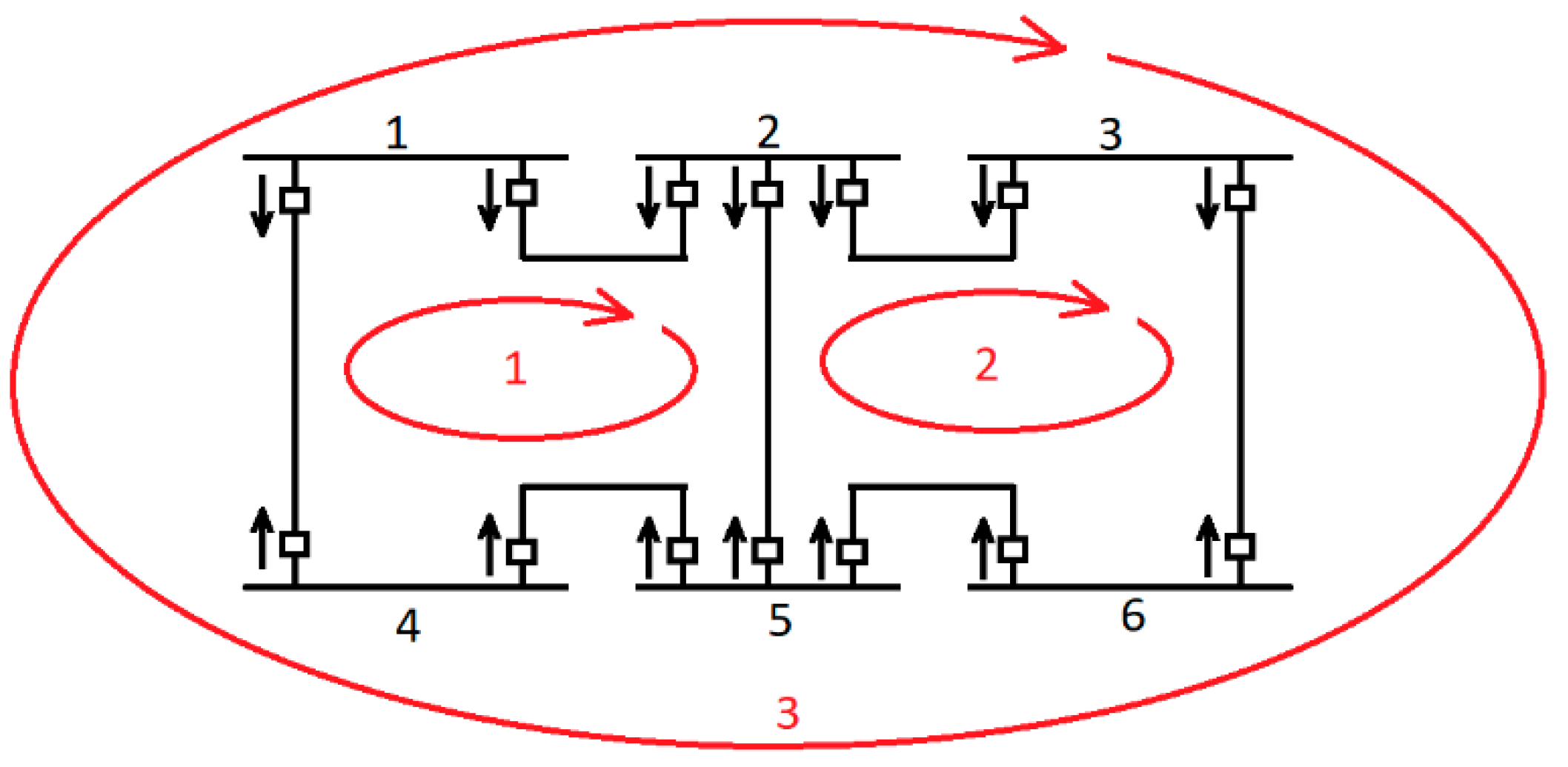
Consider the 6-bus mesh network shown in Figure 1. All relays are directional. There are 3 clockwise (CW) loops in the system. Depending upon the device(s) chosen, it may be possible to coordinate this system directly.
Coordination of the relays in CW loop 1 results in the 4 inequalities
CTI is the coordination time interval. Coordination of the relays in CW loop 2 results in the 4 inequalities
Coordination of the relays in CW loop 3 results in the 6 inequalities
There are 14 total CW coordination constraints. The same process can be carried out for the counterclockwise (CCW) loops yielding 14 additional coordination constraints. Let be the set of all coordination constraints. The optimal coordination problem becomes
For this simple 6-bus example, 28 coordination constraints are required. However, starting from an MBPS, the number of coordination constraints can be drastically reduced. As will be later shown, the MBPS of this system must have a cardinality of exactly 2. One option for the MBPS is relays 1-2 and 2-5. Choose these 2 relays as the only 2 primary relays in the system. Assume these relays are instantaneous with an operating time of . Consider again the CW constraints (1)–(14). Constraints (1), (2), (4), (7)–(9), and (14) no longer need to be considered. There are 7 additional inequalities corresponding to the 3 CCW loops. The total number of inequalities is, therefore, reduced by half from 28 to 14. This can make a drastic difference in computation time over considering all constraints without considering the MBPS. Such a reduction in the number of optimization constraints can drastically improve computation speed for large systems.
3. Methods for Determining a Minimum Breakpoint Set
In this section some methods which have been historically used to determine the MBPS are discussed. These methods will be compared to the proposed approach later in the paper. In [22] lower-upper (LU) factorization of a rectangular bus-branch adjacency matrix
where
is used to both determine whether a graph is connected and to determine a MBPS. The benefit of this method is that it allows a disjointed set to be identified so that a MBPS can be found for each subgroup. However, LU factorization involves row reduction, which can be computationally expensive for larger systems [23,24]. Additionally, as will be shown later, the solutions found in [22] are not necessarily the minimal breakpoint sets.
According to [15], the computation time for coordination increases with the size of the breakpoint set (BPS). If the cardinality of a BPS is minimal, the computational time of the directional relay coordination algorithm can improve significantly [25]. Therefore, it is advantageous to operate from a MBPS. The method proposed in [15] operates on a bus-bus adjacency matrix where represents the number of edges directly connecting buses and . The method directly focuses on breaking loops in a mesh grid to allow for radial coordination of the directional relays. However, in the first computational example of the paper, the algorithm allows for segmentation of the grid. That is, current paths may not exist between arbitrary nodes. Additional measures are needed to ensure that the computed MBPS does not isolate loads such that generators isolated along with the loads cannot support them.
If there are two directional relays “looking” toward each other on each line utilizing directional relays and a current path exists between any two arbitrary buses, the system can be effectively treated as an undirected connected graph. Where loops in a mesh grid are to be broken, it is ideal that at least one current path remains between any two arbitrary buses. Otherwise, load or generator isolation may occur in a manner such that generators become overloaded or loads become unnecessarily isolated. Establishing a minimum spanning tree may aid in alleviating this issue.
For an undirected connected graph, a minimum spanning tree is a set of edges which forms a network which connects all nodes without the presence of any redundant paths (loops). Additionally, the sum of the weights of each path in this set must be less than or equal to any other possible set of edges. That is, the total weight is unique, but the combination of edges forming the set may not be. It can be shown that any minimum spanning tree of a connected graph with vertices will have edges [26]. Furthermore, in a spanning tree, a path must exist between any two arbitrary edges and there are no loops. Therefore, because there is already one path between any two arbitrary vertices, any additional edge added to the system will result in a redundant loop. For the results in this paper, a built-in MATLAB function was used to compute the minimum spanning tree. For a more in-depth discussion of this topic, the reader is referred to [27,28,29,30].
In Reference [31], a protection relay dependency dimension (PRDD) method is introduced which considers relay coordination as a constraint in determining a MBPS. This allows for relay coordination to be carried out simultaneously. However, combining these steps yields suboptimal results for the cardinality of the breakers, as will later be seen in Section 5.
In Reference [25], an integer linear programming approach is proposed. However, as the size of the system increases, the computation time for the algorithm can increase exponentially due to the enumeration of loops involved in this algorithm [25], as will be seen in Section 5.
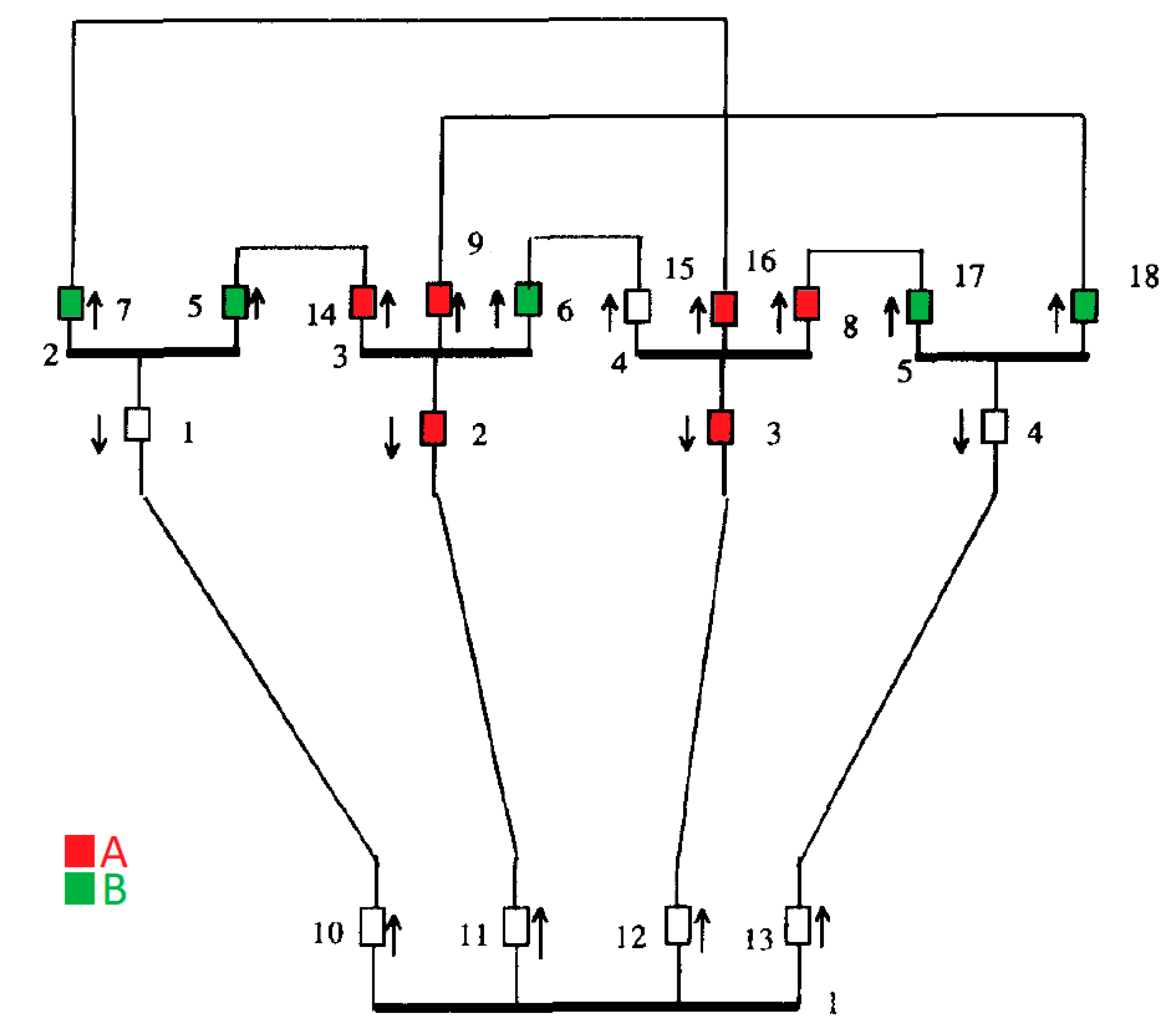
A method is proposed in [32] based upon a functional dependency approach. The cardinality of the MBPS is also discussed in this reference. Consider a system consisting of lines and buses. According to [32,33], the cardinality of the is . Let denote relay . For the 5-bus, 9-line system shown in Figure 2, the method detailed in [32] determines that the is . However, for this small system, an alternative breakpoint set can be found by visual inspection. An alternative BPS is . The existence of this smaller BPS contradicts the original conclusion that is a minimum breakpoint set. Furthermore, segments the system into 2 disjoint subsystems and . remains a single connected system. Note that no conclusion as to whether is a MBPS has been made. This assertion is addressed in Section 4.
An algorithm which avoids the computational requirement of generating all circuits (loops) in the graph is proposed in [17]. However, this method is the foundation for [32] and also concludes for the system of Figure 2 that the cardinality of the MBPS will be . Therefore, it can readily be seen that this method also yields suboptimal results.
4. Proposed Method
For the proposed method, parallel lines are treated as a single equivalent line. Let be the number of buses and be the number of lines. Define the lines as a set of lines . Let represent the index for the edge connecting nodes and . If line capacities are considered, let represent the thermal capacity of line . Define the initial edge weights as . The modified edge weights are . Each bus has an apparent load of with magnitude . and denote the active and reactive load power at bus , respectively.
In the proposed method, a graph theory method is proposed for identifying a MBPS. This algorithm seeks a minimum spanning tree for the system and identifies its complement as a MBPS. Additionally, thermal line limits can be considered to avoid overloading lines unnecessarily when the primary breakers (those in the MBPS) open. Thermal limits are enforced by iteratively perturbing the weights of lines with higher load demands. The process in summarized in Algorithm 1.
| Algorithm 1. Proposed MBPS determination algorithm. |
| Result: MBPS |
| Initialization: set , choose |
if not considering line MVA limits, then:
|
else
|
| for do |
| for do |
| if |
| end if |
| end for |
end for
|
| end if |
If is too small, line weight perturbations may not be sufficiently large to break ties where necessary. However, if is too large (near 1.0), line weight perturbations may be too large resulting in inaccurate line limits. It is suggested that (1%) be used as a heuristic to avoid these phenomena.
Theorem 1.
Given a connected grid or microgrid consisting ofbuses andlines, the cardinality of any MBPS will be
Proof.
Consider a grid with n buses. Start with some minimum spanning tree (MST). Recall that . Any MST must form a network connecting all nodes and has no loops. Define some , where the combinatorial is the total possible number of unordered pairwise connections. Assume that
non-parallel lines are added to the network. Each line added forms a loop and is, therefore, in some . Consider the which consists solely of these newly added lines. Then,
The is not unique. However, any will have the same cardinality. Therefore, Equation (24) will hold for any . □
5. Results
The MBPS is computed for the IEEE 14-, IEEE 30-, and IEEE 57-bus test systems. Additionally, the Polish Utility 3120 test system detailed in [34,35] is also examined. The computations were carried out on a Dell Latitude 7490 with an i7-8650U 1.90 GHz processor with 16 GB RAM.
5.1. MBPS Not Considering Line MVA Limits
The results of various methods from literature are summarized in Table 1. The results for the proposed method are summarized in Table 2 and the results from [22] are summarized in Table 3. Comparing the results of Table 2 and Table 3, it can be seen that the cardinality using the proposed method is improved (reduced) for the IEEE 14-bus, IEEE 30-bus, IEEE 57-bus, and Utility 3120 test cases by 3, 7, 12, and 279 relays, respectively. For the Utility 3120 case, there are 9 parallel lines corresponding to breakers and . The computation times were irregular and were too close to directly compare overall for the smaller scale systems. A single trial was run for the proposed method, and for [22] there is no statement about the number of how many trials was run to yield the published computation times. However, for the large-scale Utility 3120 system, the computation time was drastically improved. This is likely due to the computational inefficiency of computing the LU factorization for a large system as was done in [22]. Additionally, the results of the proposed method seen in Table 2 are consistent with Theorem 1. Note that in Table 2, each set of parallel lines is considered as a single equivalent line. Particularly, for the Utility 3120 case, corresponds to a pair of breakers on a set of parallel lines. Considering these separately, the cardinality of the MBPS increases to The complete results for the Utility 3120 test case are given in Appendix A.
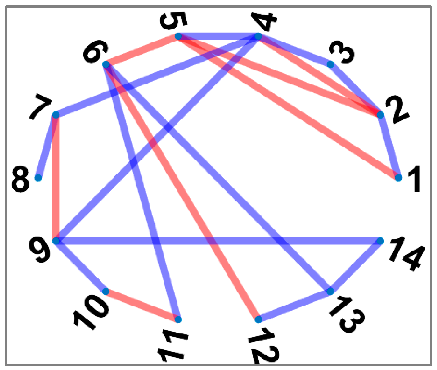
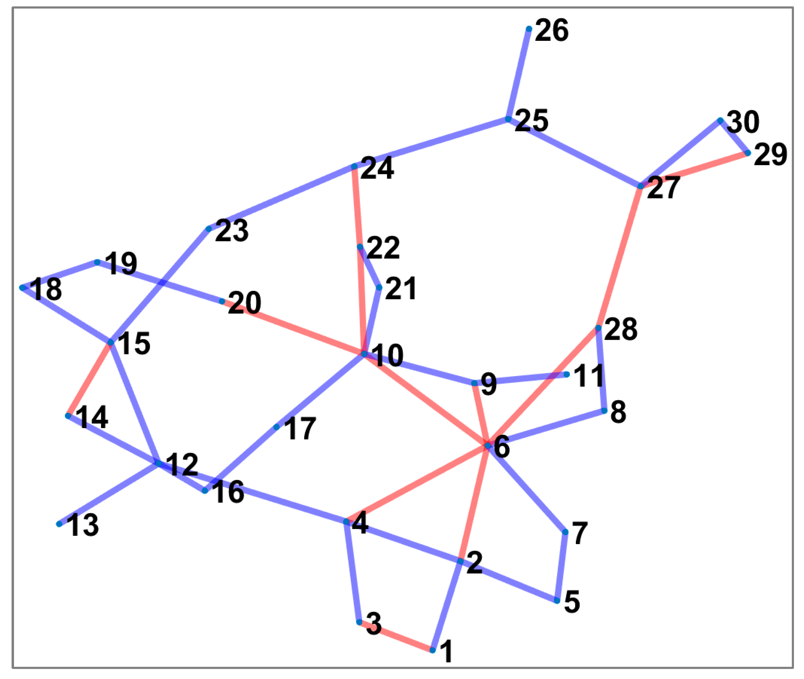
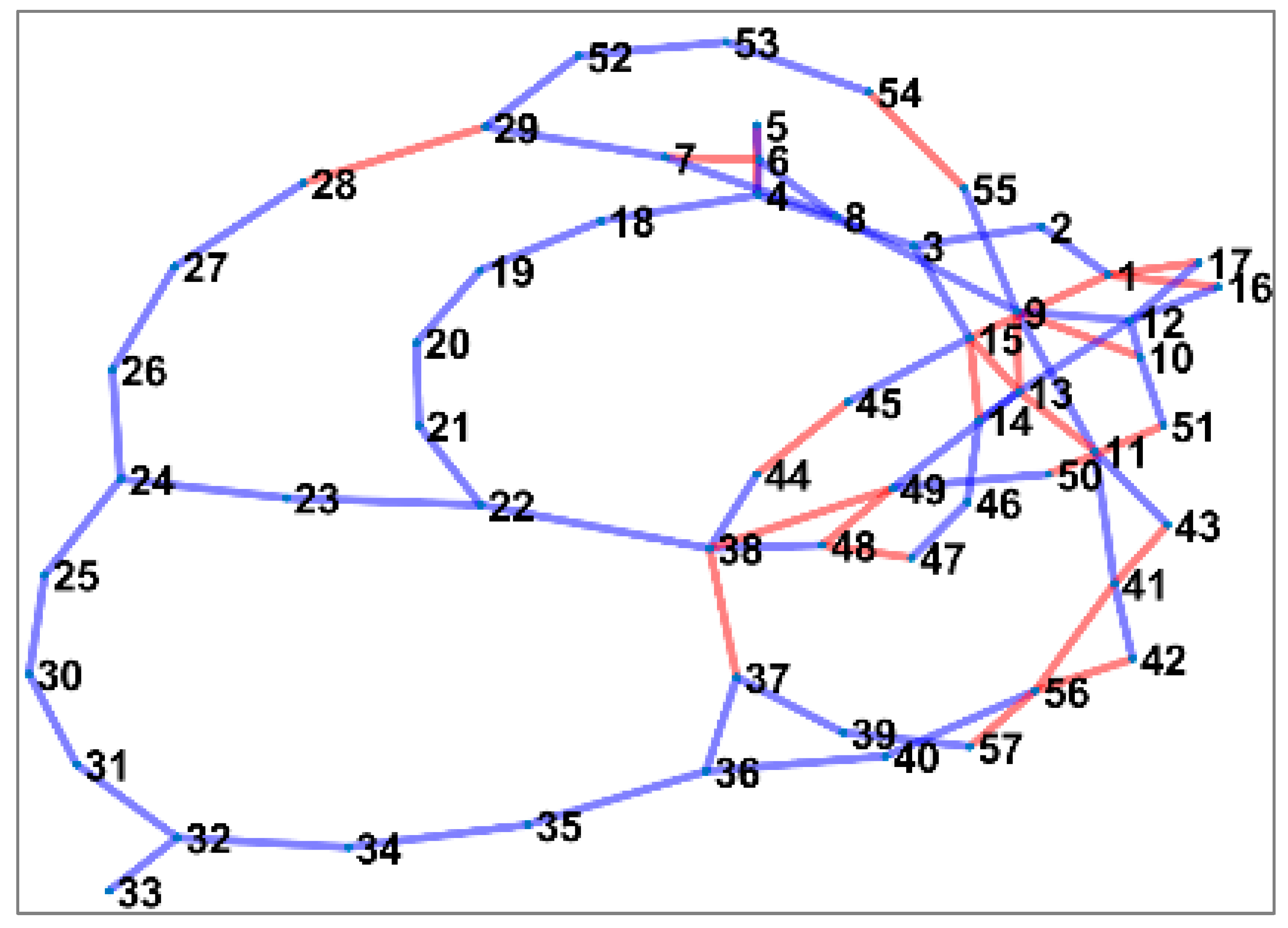
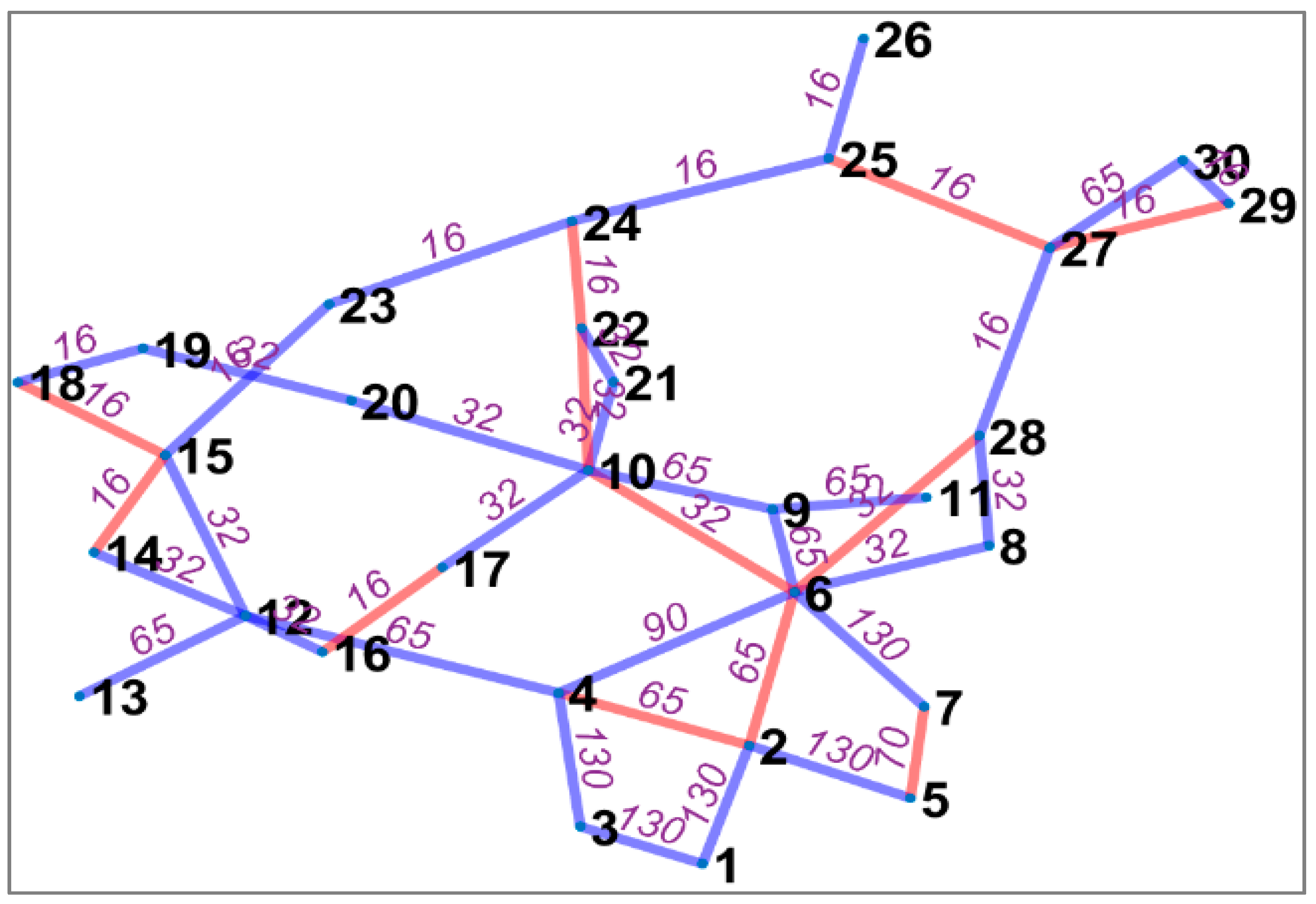
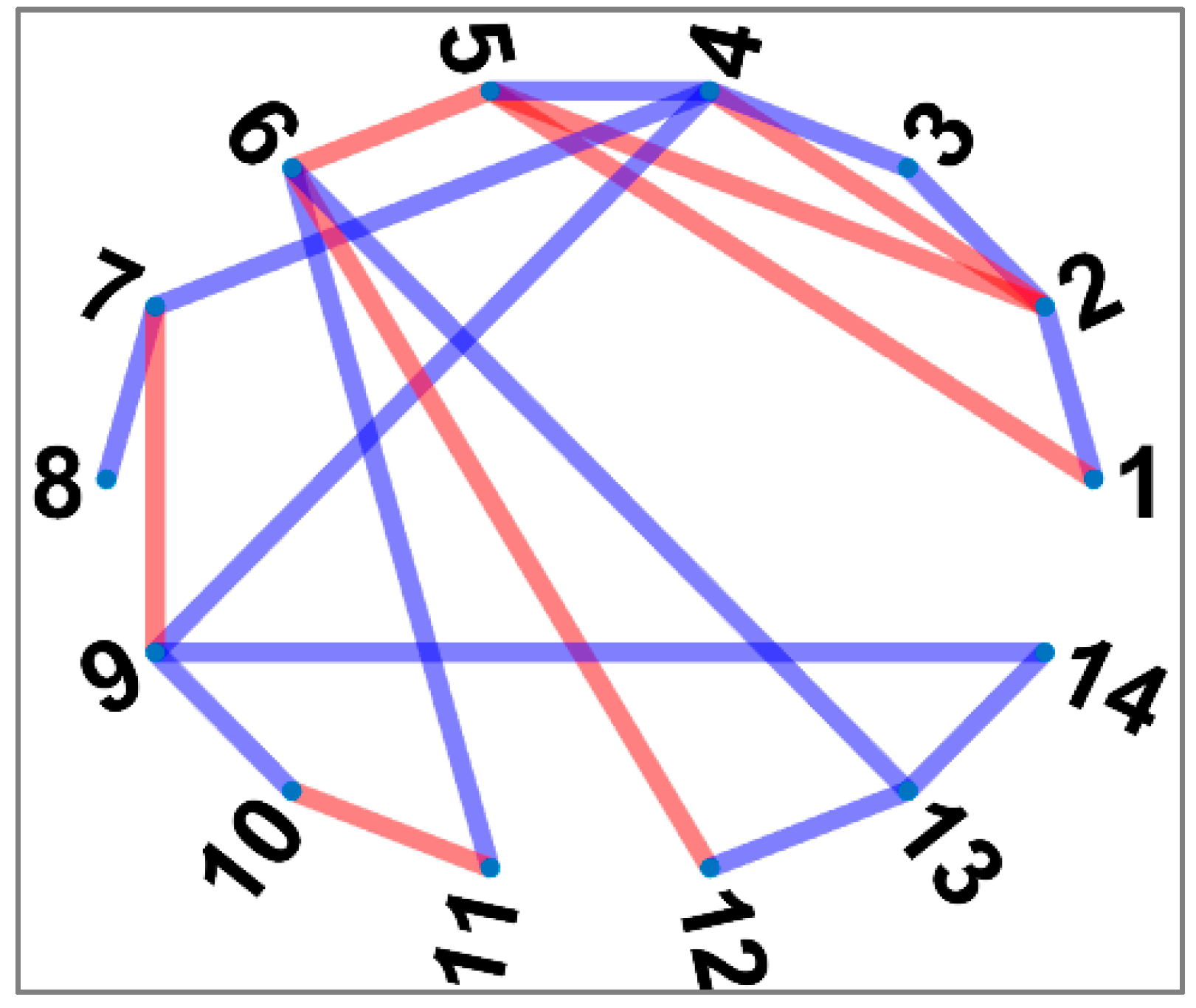
Visual representations of the IEEE 14-, 30-, and 57-bus systems are shown in Figure 3, Figure 4 and Figure 5, respectively. In each figure, the minimum spanning tree is marked in blue and the MBPS is marked in red. The complementary nature of these sets can be seen in each figure. The combination of these two disjoint sets form the entirety of the grid for each case, as is desired. It can readily be seen for each case that adding to the cardinality of the MBPS will result in a disjointed network and that reducing the cardinality will result in at least one loop in the network. In Table 1, a comparison is made among several MBPS computations from literature. In comparing Table 1 and Table 2, the cardinality MBPS is improved for all cases implying that the results of Table 1 are breakpoint sets (BPSs), but not MBPSs. In Table 2 and Table 3, additional computational time information is given for the proposed method (Table 2) and the method of [22] (Table 3). For each case, case the cardinality is improved. The computation times were relatively close together for small to moderate-sized systems. However, for large 3120 bus case, there was a drastic reduction in computation time.
5.2. MBPS Considering Line MVA Limits
As earlier stated, it is possible that line capacities are limited. In such cases, higher capacity lines should be kept in service for as long as possible. The updated MBPS for the IEEE 30-bus system is shown in Figure 6 and is summarized in Table 7. The line MVA (megavolt-ampere) ratings for the 41 lines of the IEEE 30-bus test case as documented in [37] are summarized in column 5 of Table 8. The MVA capacity of each line is italicized and colored purple. A gradient/Hessian-based optimal power flow (OPF) is computed to validate this new topology using Matpower 6.0b1. The reason that an OPF is computed is to establish that a feasible operating point exists for the proposed topology. Any power flow computation could be used to serve this same purpose. The choice of an OPF over a general power flow is purely arbitrary. The cost function for each generator as defined in [37] is
The OPF results are summarized in Table 8. Each line remains within its desired operating range and there are no loops in the system. Therefore, the computed MBPS is valid allowing the system to continue to operate with all primary breakers open without overloading any branch elements.
5.3. Post Fault Reconfiguration
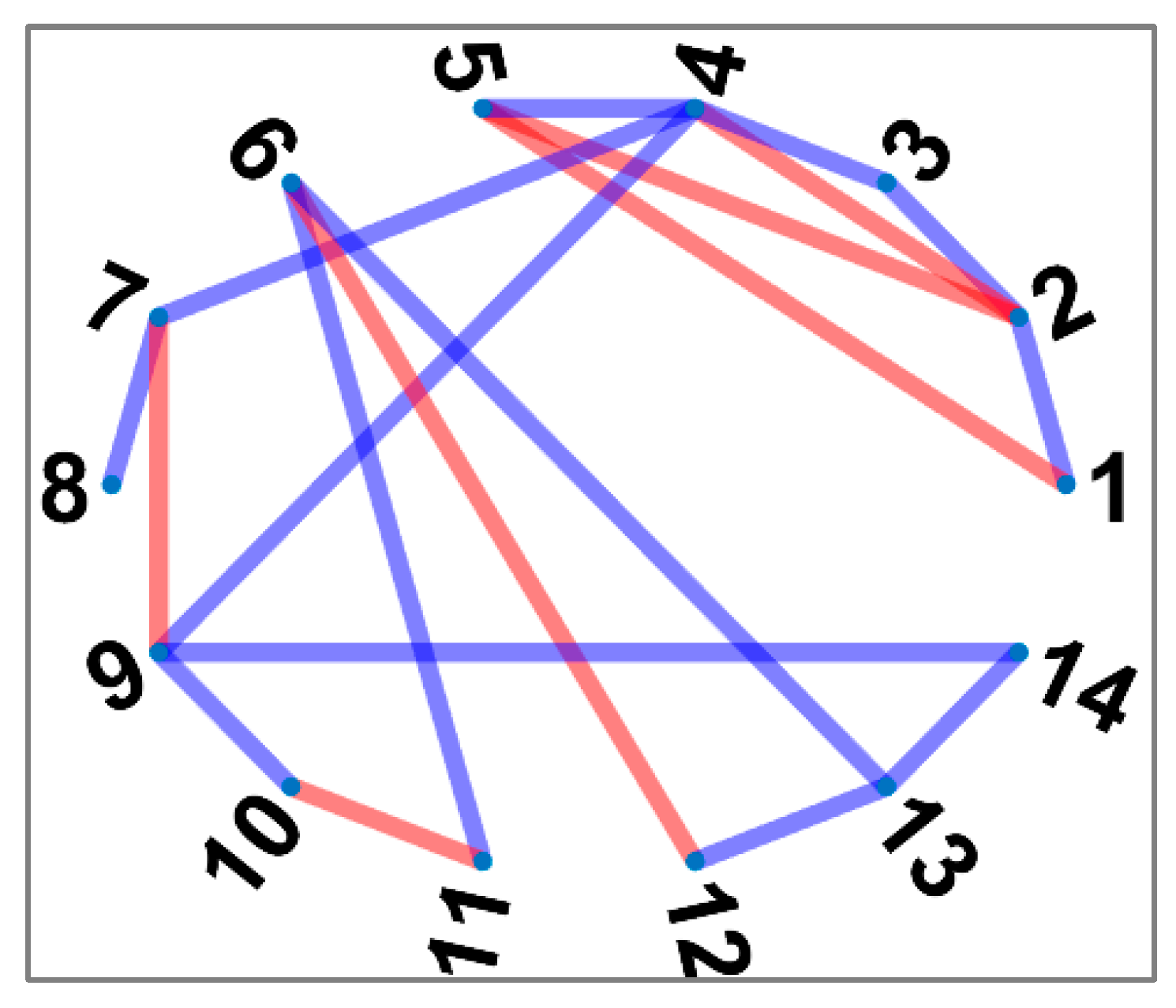
Consider again the result of Figure 3 (repeated below as Figure 7 for convenience). It may be desired to automatically reconfigure relay coordination after a breaker or recloser has cleared a fault. Assume that instantaneous reclosers are placed on each line in the MBPS. Furthermore, assume that there is a sustained fault on line 6-5. This fault will be removed from service by the radial relay coordination after MBPS opens to remove all loops. A new MBPS configuration can be determined after removing this line from the next MBPS computation.
5.3.1. Reconfiguration 1: Line 6-5 Removed
After the fault on line 6-5 clears, a non-MBPS breaker remains open, reducing the cardinality of the new MBPS by 1. This is because the missing line has effectively become a forced member of the full MBPS. Overall, 7 breakers are still open in the system on the inception of an additional fault. The only difference is that one (6-5) is now always open. This result is summarized in Figure 8.
5.3.2. Reconfiguration 2: Line 9-4 Removed
6. Conclusions
In this paper, it was found that the proposed method yielded a true MBPS for each case examined. The cardinality of the MBPS for the proposed method was the lowest for all circuits, and for larger systems there was a substantial improvement in computation time compared to results from literature. Compared to the best prior results from literature, the cardinalities were decreased by 30, 33.33, 35.29, and 33.06%, respectively, for the IEEE 14-bus, IEEE 30-bus, IEEE 57-bus, and Utility 3120 bus test cases, respectively. Additionally, a proof was carried out which established that the cardinality of the MBPS for any system consisting of buses and lines must equal exactly . All MBPSs determined using the proposed method were consistent with the result of this proof, establishing that the proposed results were true MBPSs. Also, when line limits were considered for the IEEE 30-bus test case, the proposed algorithm was able to generate a MBPS which allowed for a valid OPF to be computed so that no branch element is overloaded if all primary breakers are open at once under normal operating conditions. That is, if all primary breakers (MBPS) are opened to clear a fault, the system can continue to run if there are no transient instabilities present and the fault occurs on and is cleared by a breaker in the MBPS.
Additionally, the proposed algorithm was able to determine reconfiguration after successive fault clearances to maintain a current path between all nodes. This process may be repeated each time a line is lost until the cardinality of the MBPS reaches zero. Beyond this point, further breaker trips will partition the system.
Overall, the proposed Algorithm was found to determine a true MBPS each time it was applied. The simplicity and lack of computational intensity required for this method allows for fast application of the algorithm as needed. The proposed method is intended as a preprocessing step towards optimal relay coordination. Fast computation of optimal relay setting is required for efficient application of adaptive protection.
In future work, the goal will be to use the computed MBPS to initialize the computation of an optimal relay coordination process. DERs will be considered and an optimization will be performed to minimize all operating times with the coordination times of backup relays being the constraints. Also, closing times of reclosers in the MBPS need to be considered. Closing too many reclosers all at once, in too short of a time frame, or too quickly could result in transient instability. This is not expected to be problematic because additional current paths are being added when the recloser closes, reducing the burden on lines already active. However, this should be further investigated to draw a more concrete conclusion.
Author Contributions
Conceptualization, R.C.M., M.J.R., and A.K.S.; methodology, R.C.M. and A.K.S.; software, R.C.M; validation, R.C.M.; formal analysis, R.C.M.; investigation, R.C.M.; resources, M.J.R.; data curation, R.C.M.; writing—original draft preparation, R.C.M.; writing—review and editing, A.K.S. and M.J.R.; visualization, R.C.M.; supervision, M.J.R. and A.K.S.; project administration, M.J.R.; funding acquisition, M.J.R.
Funding
This research was funded by U.S Department of Energy’s National Nuclear Security Administration under contract DE-NA-0003525.
Acknowledgments
Sandia National Laboratories is a multimission laboratory managed and operated by National Technology & Engineering Solutions of Sandia, LLC, a wholly owned subsidiary of Honeywell International Inc., for the U.S. Department of Energy’s National Nuclear Security Administration under contract DE-NA0003525. This paper describes objective technical results and analysis. Any subjective views or opinions that might be expressed in the paper do not necessarily represent the views of the U.S. Department of Energy or the United States Government.
Conflicts of Interest
The authors declare no conflict of interest.
Appendix A. Utility 3120 Complete MBPS Results
The 565 distinct breakers in the MBPS for the Utility 3120 bus test case are detailed below. B_i_j represents the breaker on line connecting nodes i and j. The single parallel breaker is highlighted in green. The data are listed here in their entirety for the sake of repeatability of the results. Again, different MBPSs may exist. However, according to the Theorem 1, they must all have the exact same cardinality.
B_35_25, B_36_24, B_36_30, B_37_32, B_38_37, B_38_108, B_41_184, B_57_55, B_59_58, B_69_68, B_71_70, B_72_55, B_73_57, B_73_72, B_75_74, B_76_55, B_77_72, B_77_76, B_106_105, B_107_41, B_108_107, B_118_117, B_121_149, B_122_121, B_124_123, B_129_128, B_130_145, B_132_116, B_133_123, B_133_132, B_135_134, B_136_78, B_137_136, B_139_137, B_139_138, B_141_140, B_142_119, B_143_142, B_145_144, B_149_147, B_153_152, B_167_153, B_168_167, B_174_173, B_181_180, B_184_187, B_184_197, B_187_186, B_188_168, B_189_188, B_194_193, B_196_168, B_196_195, B_196_198, B_199_178, B_199_198, B_202_178, B_202_201, B_203_201, B_206_205, B_215_239, B_217_221, B_222_221, B_226_225, B_228_234, B_233_235, B_235_234, B_237_236, B_239_238, B_259_258, B_324_323, B_371_370, B_403_525, B_418_457, B_437_436, B_444_443, B_476_475, B_486_485, B_487_486, B_497_496, B_508_354, B_517_436, B_518_503, B_519_473, B_524_474, B_525_375, B_525_427, B_546_545, B_557_543, B_560_559, B_562_561, B_574_573, B_579_571, B_588_587, B_597_528, B_598_597, B_611_792, B_618_617, B_624_623, B_631_651, B_638_526, B_647_645, B_670_669, B_702_701, B_710_625, B_739_738, B_741_723, B_741_737, B_749_748, B_753_746, B_757_756, B_759_758, B_761_760, B_768_767, B_773_750, B_773_755, B_774_772, B_784_780, B_790_526, B_794_564, B_800_781, B_804_778, B_806_805, B_810_609, B_810_809, B_811_589, B_811_798, B_812_811, B_815_814, B_822_821, B_826_825, B_828_687, B_830_829, B_832_831, B_867_1112, B_868_867, B_917_925, B_922_615, B_923_872, B_923_922, B_924_940, B_929_858, B_947_834, B_957_894, B_960_945, B_960_948, B_960_955, B_960_959, B_964_962, B_965_960, B_966_959, B_966_965, B_969_954, B_971_864, B_971_970, B_975_850, B_993_867, B_997_982, B_1002_1011, B_1002_1025, B_1005_1001, B_1007_1000, B_1008_1000, B_1012_981, B_1012_1011, B_1018_1017, B_1019_1020, B_1020_988, B_1023_1027, B_1028_1027, B_1028_1029, B_1031_914, B_1031_982, B_1032_986, B_1032_1031, B_1035_1024, B_1037_867, B_1038_937, B_1038_1037, B_1044_1043, B_1046_1045, B_1047_1039, B_1054_839, B_1054_908, B_1054_942, B_1054_1053, B_1055_1044, B_1056_1058, B_1057_1051, B_1064_1062, B_1069_1093, B_1070_1053, B_1076_1052, B_1077_1012, B_1078_1043, B_1079_999, B_1079_1078, B_1083_1068, B_1085_1079, B_1086_991, B_1086_1117, B_1087_1048, B_1088_932, B_1090_1086, B_1097_892, B_1102_978, B_1104_1009, B_1105_903, B_1105_1104, B_1108_1089, B_1110_967, B_1111_1075, B_1113_860, B_1119_1096, B_1119_1099, B_1119_1118, B_1120_1101, B_1122_980, B_1123_1087, B_1125_1124, B_1127_1043, B_1289_1383, B_1301_1875, B_1305_1274, B_1383_1377, B_1439_1438, B_1444_1926, B_1470_1473, B_1529_1295, B_1529_1296, B_1532_1531, B_1544_1665, B_1546_1188, B_1546_1545, B_1562_1509, B_1564_1563, B_1586_1518, B_1590_1992, B_1599_1839, B_1609_1702, B_1655_1665, B_1658_2020, B_1666_1665, B_1667_1589, B_1674_1673, B_1679_1881, B_1683_1682, B_1703_1702, B_1705_2099, B_1707_1706, B_1728_1727, B_1730_1729, B_1739_1483, B_1746_1775, B_1747_1738, B_1747_1746, B_1765_1764, B_1791_1790, B_1799_1798, B_1804_2003, B_1808_1382, B_1829_1849, B_1834_1833, B_1842_1841, B_1854_1853, B_1860_1859, B_1864_1863, B_1874_1873, B_1876_1875, B_1880_1443, B_1886_1885, B_1906_2181, B_1908_2091, B_1916_1915, B_1928_1927, B_1930_2146, B_1936_1935, B_1940_1939, B_1943_1942, B_1945_1944, B_1947_1949, B_1955_1954, B_1964_1963, B_1975_2103, B_1982_2009, B_1986_1985, B_1988_1987, B_1993_1744, B_1996_1979, B_1997_1996, B_1998_1993, B_2003_2002, B_2016_2015, B_2022_2021, B_2024_2023, B_2025_1630, B_2025_1890, B_2026_1631, B_2028_2027, B_2036_2035, B_2038_2037, B_2043_2042, B_2045_1872, B_2045_2044, B_2047_2046, B_2053_2052, B_2055_2054, B_2057_2097, B_2058_1903, B_2059_2058, B_2061_2188, B_2063_2062, B_2065_2064, B_2069_2068, B_2075_2074, B_2079_2078, B_2081_2080, B_2083_1992, B_2083_1998, B_2083_2082, B_2085_2084, B_2087_2086, B_2093_2092, B_2095_2094, B_2096_1911, B_2096_2072, B_2097_2073, B_2097_2096, B_2110_2109, B_2111_2008, B_2112_1982, B_2112_2111, B_2114_2113, B_2117_2101, B_2118_2117, B_2120_2175, B_2122_1876, B_2124_1652, B_2125_1680, B_2125_1924, B_2126_1462, B_2126_1466, B_2126_1679, B_2128_2127, B_2130_2129, B_2132_2131, B_2134_2133, B_2141_2140, B_2144_1950, B_2144_1981, B_2145_1624, B_2145_1850, B_2147_1674, B_2148_2012, B_2152_2151, B_2154_2153, B_2156_2155, B_2158_2157, B_2162_2161, B_2166_1421, B_2166_1425, B_2167_1884, B_2169_2168, B_2171_2170, B_2176_2143, B_2183_2182, B_2185_2184, B_2187_2186, B_2189_2188, B_2191_2190, B_2192_1669, B_2192_1940, B_2193_1809, B_2195_2194, B_2199_2198, B_2201_1968, B_2201_2200, B_2205_2204, B_2209_2208, B_2211_2210, B_2214_2218, B_2223_2222, B_2225_2224, B_2227_2226, B_2231_2230, B_2244_2644, B_2254_2489, B_2300_2415, B_2343_2787, B_2384_2557, B_2400_2472, B_2407_2374, B_2418_2417, B_2419_2571, B_2426_2571, B_2430_2369, B_2449_2402, B_2455_2318, B_2459_2765, B_2480_2374, B_2488_2480, B_2498_2577, B_2513_2511, B_2529_2528, B_2535_2534, B_2537_2536, B_2541_2643, B_2552_2576, B_2556_2555, B_2574_2573, B_2578_2577, B_2585_2532, B_2587_2644, B_2588_2528, B_2592_2499, B_2595_2479, B_2598_2597, B_2601_2600, B_2602_2684, B_2604_2603, B_2613_2557, B_2618_2517, B_2623_2788, B_2628_2566, B_2629_2627, B_2631_2670, B_2636_2643, B_2640_2733, B_2641_2504, B_2647_2748, B_2649_2497, B_2651_2523, B_2657_2533, B_2666_2665, B_2668_2667, B_2669_2574, B_2673_2672, B_2674_2321, B_2674_2599, B_2676_2675, B_2677_2576, B_2677_2581, B_2681_2658, B_2687_2726, B_2691_2750, B_2697_2566, B_2697_2625, B_2702_2386, B_2707_2626, B_2710_2752, B_2716_2715, B_2718_2695, B_2719_2725, B_2723_2680, B_2728_2528, B_2729_2572, B_2734_2706, B_2738_2553, B_2738_2579, B_2739_2730, B_2741_2575, B_2742_2680, B_2744_2787, B_2745_2423, B_2746_2652, B_2751_2388, B_2753_2756, B_2760_2653, B_2761_2565, B_2766_2765, B_2768_2767, B_2770_2586, B_2774_2773, B_2776_2506, B_2781_2697, B_2784_2783, B_2789_2621, B_2790_2574, B_2814_3095, B_2835_2834, B_2846_2849, B_2851_3068, B_2868_2867, B_2869_2868, B_2874_2867, B_2876_2875, B_2878_2877, B_2895_3063, B_2908_2878, B_2911_2909, B_2914_2899, B_2925_2924, B_2925_2941, B_2926_2954, B_2932_3045, B_2954_2957, B_2955_2954, B_2955_2958, B_2958_2957, B_2959_2954, B_2960_2847, B_2961_2969, B_2962_3096, B_2964_2919, B_2965_2990, B_2972_2931, B_2973_2972, B_2973_2996, B_2974_2849, B_2975_2915, B_2979_2978, B_2981_2844, B_2988_3056, B_2993_3037, B_2997_2865, B_3000_3078, B_3001_3065, B_3006_3019, B_3009_2992, B_3012_3011, B_3015_3014, B_3015_3016, B_3016_3101, B_3019_2896, B_3027_3025, B_3028_3030, B_3029_3036, B_3030_3029, B_3031_2939, B_3032_3080, B_3034_3024, B_3038_2957, B_3039_2861, B_3042_2936, B_3043_2994, B_3044_2869, B_3047_2937, B_3049_3048, B_3050_2893, B_3052_3054, B_3054_3053, B_3055_3052, B_3059_3097, B_3062_3079, B_3064_2927, B_3066_3095, B_3070_3073, B_3071_3031, B_3074_3073, B_3075_3072, B_3077_2958, B_3082_3030, B_3083_2795, B_3084_3083, B_3096_3095, B_3098_3097, B_3099_3074, B_3100_3086, B_3101_3100, B_3107_3106, B_3114_120, B_3116_181, B_3117_170, B_3118_62, B_3120_236
References
- IEEE Standard for Interconnection and Interoperability of Distributed Energy Resources with Associated Electric Power Systems Interfaces; IEEE Std 1547-2018 (Revision of IEEE Std 1547-2003); IEEE: Piscataway, NJ, USA, 2018; pp. 1–138. [CrossRef]
- Venkata, S.S.; Reno, M.J.; Bower, W.; Manson, S.; Reilly, J.; Sey, G.W., Jr. Microgrid Protection: Advancing the State of the Art; SAND2019-3167; Sandia National Laboratories: Albuquerque, NM, USA, 2019. [Google Scholar]
- Seuss, J.; Reno, M.J.; Broderick, R.J.; Grijalva, S. Maximum PV Size Limited by the Impact to Distribution Protection. In Proceedings of the IEEE Photovoltaic Specialists Conference, Denver, CO, USA, 14–19 June 2015. [Google Scholar]
- Matthews, R.C.; Hossain-McKenzie, S.; Reno, M.J. Fault Current Correction Strategies for Effective Fault Location in Inverter-Based Systems. In Proceedings of the 46th IEEE Photovoltaic Specialists Conference (PVSC 46), Chicago, IL, USA, 16–21 June 2019. [Google Scholar]
- Kirthiga, M.V.; Muppiddi, P. A case study for controlled islanding based on line contingency ranking in autonomous micro-grids. In Proceedings of the AFRICON Conference, Pointe-Aux-Piments, Mauritius, 9–12 September 2013. [Google Scholar]
- Jane, R.; Parker, G.G.; Weaver, W.; Matthews, R.; Rizzo, D.; Cook, M. Optimal Power Management of Vehicle Sourced Military Outposts. SAE Intern. J. Commer. Veh. 2017, 10, 132–143. [Google Scholar] [CrossRef]
- Hossain-McKenzie, S.; Piesciorovsky, E.C.; Reno, M.J.; Hambrick, A.J.C. Microgrid Fault Location: Challenges and Solutions; Sandia National Laboratories: Albuquerque, NM, USA, 2018. [Google Scholar]
- Keil, T.; Jäger, J. Advanced coordination method for overcurrent Protection Relays Using Nonstandard Tripping Characteristics. IEEE Trans. Power Deliv. 2008, 23, 52–57. [Google Scholar] [CrossRef]
- Kargar, H.K.; Abyaneh, H.A.; Ohis, V.; Meshkin, M. Pre-processing of the optimal coordination of overcurrent relays. Electr. Power Syst. Res. 2005, 75, 134–141. [Google Scholar] [CrossRef]
- Abyaneh, H.A.; Al-Dabbagh, M.; Karegar, H.K.; Sadeghi, S.H.H.; Khan, R.A.J. A newoptimal approach for coordination of overcurrent relays in interconnected power systems. IEEE Trans. Power Deliv. 2003, 18, 430–435. [Google Scholar] [CrossRef]
- Sharifian, H.; Abyaneh, H.A.; Salman, S.K.; Mohammadi, R.; Razavi, F. Determination of the Minimum Break Point Set Using Expert System and Genetic Algorithm. IEEE Trans. Power Deliv. 2010, 25, 1284–1295. [Google Scholar] [CrossRef]
- Abyaneh, H.A.; Al-Dabbagh, M.; Sedeghi, H.; Kazemikargar, H. A comprehensive method for break points finding based on expert system for protection coordination in power systems. Electr. Power Syst. Res. 2007, 77, 660–672. [Google Scholar] [CrossRef]
- Gajbhiye, R.; De, A.; Helwade, R.; Soman, S. A simple and efficient approach to determination of minimum set of break point relays for transmission protection system coordination. In Proceedings of the International Conference on Future Power Systems, Amsterdam, The Netherlands, 18 November 2005. [Google Scholar]
- Meliopoulos, A.P.S.; Cokkinides, G.J.; Tan, Z.; Choi, S.; Lee, Y.; Myrda, P. Setting-Less Protection: Feasibility Study. In Proceedings of the 46th Hawaii International Conference on System Sciences, Maui, HI, USA, 7–10 January 2013. [Google Scholar]
- Yang, X.; Shi, D.; Chen, J.; Duan, X. Determination of Break Point Set for Directional Relay Coordination Based on Analysis of Breaking Loop. In Proceedings of the IEEE Power Engineering Society General Meeting, Montreal, QC, Canada, 18–22 June 2006. [Google Scholar]
- Prodan, I.; Stoican, F.; Zio, E. On a fault tolerant strategy for efficient energy management in microgrid systems. IFAC-PapersOnLine 2015, 48, 458–463. [Google Scholar] [CrossRef]
- Hosseinzadeh, M.; Salmasi, F.R. Fault-Tolerant Supervisory Controllerfor a Hybrid AC/DC Micro-Grid. IEEE Trans. Smart Grid 2018, 9, 2809–2823. [Google Scholar] [CrossRef]
- Goud, P.C.D.; Gupta, R. Dual-mode control of multi-functional converter in solar PV system for small off-grid applications. IET Power Electron. 2019, 12, 2851–2857. [Google Scholar] [CrossRef]
- Igbinovia, F.O.; Fandi, G.; Müller, Z.; Švec, J.; Tlusty, J. Cost implication and reactive power generating potential of the synchronous condenser. In Proceedings of the 2nd International Conference on Intelligent Green Building and Smart Grid (IGBSG), Prague, Czech Republic, 27–29 June 2016. [Google Scholar]
- Moxley, R.; Fodero, K. High-Speed Distribution Protection Made Easy: Communications-Assisted Protection Schemes for Distribution Applications. SEL J. Reliab. Power 2012, 3, 1–9. [Google Scholar]
- Zeineldin, H.H.; Sharaf, H.M.; Ibrahim, D.K.; El-Zahab, E.E.-D.A. Optimal Protection Coordination for Meshed Distribution Systems With DG Using Dual Setting Directional Over-Current Relays. IEEE Trans. Smart Grid 2015, 6, 115–123. [Google Scholar] [CrossRef]
- Liu, L.; Fu, L. Minimum Breakpoint Set Determination for Directional Overcurrent Relay Coordination in Large-Scale Power Networks via Matrix Computations. IEEE Trans. Power Deliv. 2017, 32, 1784–1789. [Google Scholar] [CrossRef]
- Zill, D.G.; Wright, W.S. Advanced Engineering Mathematics, 5th ed.; Burlington: Burlington, NJ, USA; Jones & Bartlett Learning, LLC: Burlington, MA, USA, 2014. [Google Scholar]
- Shen, Y.-Q.; Ypma, T.J. Solving Separable Nonlinear Equations Using LU Factorization. ISRN Math. Anal. 2013, 2013, 1–5. [Google Scholar] [CrossRef] [PubMed]
- Gajbhiye, R.K.; De, A.; Soman, S.A. Computation of Optimal Break Point Set of Relays—An Integer Linear Programming Approach. IEEE Trans. Power Deliv. 2007, 22, 2087–2098. [Google Scholar] [CrossRef]
- Hillier, F.S.; Lieberman, G.J. Introduction to Operations Research, 8th ed.; McGraw-Hill Companies, Inc.: New York, NY, USA, 2005. [Google Scholar]
- Sun, X.; Chang, C.; Su, H.; Rong, C. Novel Degree Constrained Minimum Spanning Tree Algorithm Based on an Improved Multicolony Ant Algorithm. Math. Probl. Eng. 2015, 2015, 601782. [Google Scholar] [CrossRef]
- Hasuike, T.; Katagiri, H.; Tsuda, H. Risk-Control Approach for a Bottleneck Spanning Tree Problem with the Total Network Reliability under Uncertainty. J. Appl. Math. 2012, 2012, 364086. [Google Scholar] [CrossRef]
- Cormen, T.H.; Leiserson, C.E.; Rivest, R.L.; Stein, C. Minimum Spanning Trees, in Introduction to Algotithms; The MIT Press: Cambridge, MA, USA, 2009; pp. 623–642. [Google Scholar]
- Hillier, F.S.; Lieberman, G.J. The Minimum Spanning Tree Problem, in Introduction to Operations Research, 8th ed.; McGraw-Hill: New York, NY, USA, 2005; pp. 384–388. [Google Scholar]
- Yue, Q.; Lu, F.; Yu, W.; Wang, J. A Novel Algorithm to Determine Minimum Break Point Set for Optimum Cooperation of Directional Protection Relays in Multiloop Networks. IEEE Trans. Power Deliv. 2006, 21, 1114–1119. [Google Scholar] [CrossRef]
- Elrefaie, H.B.; Irving, M.R. Determination of minimum break point set for protection co-ordination using a functional dependency concept. Int. J. Electr. Power Energy Syst. 2010, 15, 371–375. [Google Scholar] [CrossRef]
- Prasad, V.C.; Rao, K.S.P.; Rao, A.S. Coordination of directional relays without generating all circuits. IEEE Trans. Power Deliv. 1991, 6, 584–590. [Google Scholar] [CrossRef]
- Korab, R. Case3120, MATPOWER. 22 October 2014. Available online: https://matpower.org/docs/ref/matpower5.0/case3120sp.html (accessed on 29 July 2019).
- Zimmerman, R.D.; Murillo-S´anchez, C.E.; Thomas, R.J. MATPOWER: Steady-state operations, planning and analysis tools for power systems research and education. IEEE Trans. Power Deliv. 2011, 26, 12–19. [Google Scholar] [CrossRef]
- Damborg, M.; Venkata, S. Specification of Computer-aided Design of Transmission Protection Systems; Electric Power Research Institute: Palo Alto, CA, USA, 1984. [Google Scholar]
- Alsac, O.; Stott, B. Optimal Load Flow with Steady-State Security. IEEE Trans. Power Appar. Syst. 1974, PAS-93, 745–751. [Google Scholar] [CrossRef] [Green Version]
Figure 1.
A 6-bus mesh network example.

Figure 2.
A 5-bus test case from [32]. is the a minimum breakpoint set (MBPS) computed using the methodology detailed in [32]. is an alternative breakpoint set (BPS) of lower cardinality identified by visual inspection. The existence of contradicts the conclusion that is a MBPS.

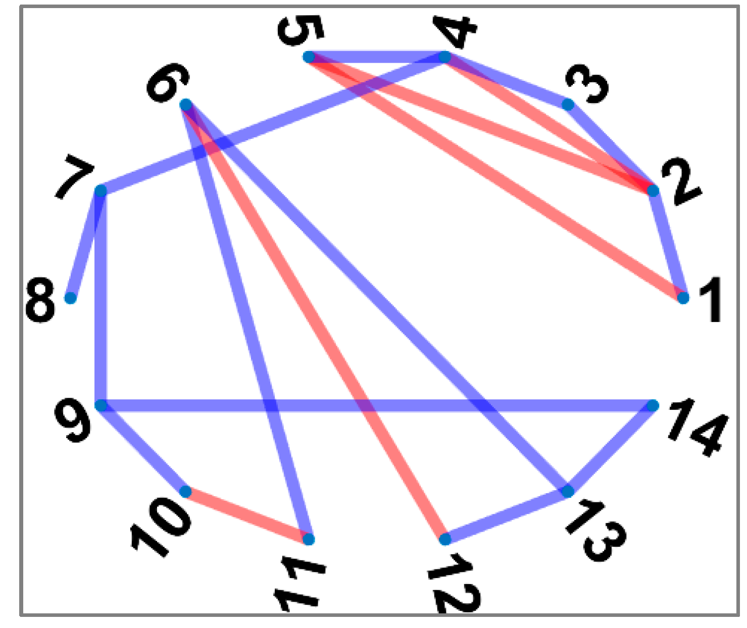
Figure 3.
IEEE 14-bus test system MBPS results using the proposed algorithm (minimum spanning tree is blue and MBPS is red). The full MBPS for this case is summarized in Table 4.
Figure 3.
IEEE 14-bus test system MBPS results using the proposed algorithm (minimum spanning tree is blue and MBPS is red). The full MBPS for this case is summarized in Table 4.

Figure 4.
IEEE 30-bus test system MBPS results using the proposed algorithm (minimum spanning tree is blue and MBPS is red). The full MBPS for this case is summarized in Table 5.
Figure 4.
IEEE 30-bus test system MBPS results using the proposed algorithm (minimum spanning tree is blue and MBPS is red). The full MBPS for this case is summarized in Table 5.

Figure 5.
IEEE 57-bus test system MBPS results using the proposed algorithm (minimum spanning tree is blue and MBPS is red). The full MBPS for this case is summarized in Table 6.
Figure 5.
IEEE 57-bus test system MBPS results using the proposed algorithm (minimum spanning tree is blue and MBPS is red). The full MBPS for this case is summarized in Table 6.

Figure 6.
IEEE 30-bus MBPS results considering thermal line limits. The full MBPS for this case is summarized in Table 7.
Figure 6.
IEEE 30-bus MBPS results considering thermal line limits. The full MBPS for this case is summarized in Table 7.

Figure 7.
IEEE 14-bus test system MBPS results using the proposed algorithm (minimum spanning tree is blue and MBPS is red).
Figure 7.
IEEE 14-bus test system MBPS results using the proposed algorithm (minimum spanning tree is blue and MBPS is red).

Figure 8.
IEEE 14-bus test system reconfiguration after line 6-5 has cleared a fault algorithm (minimum spanning tree is blue and MBPS is red).
Figure 8.
IEEE 14-bus test system reconfiguration after line 6-5 has cleared a fault algorithm (minimum spanning tree is blue and MBPS is red).

Figure 9.
IEEE 14-bus test system reconfiguration after line 9-4 has cleared fault algorithm (minimum spanning tree is blue and MBPS is red).
Figure 9.
IEEE 14-bus test system reconfiguration after line 9-4 has cleared fault algorithm (minimum spanning tree is blue and MBPS is red).


Table 1.
Comparison of MBPS cardinalities of various methods.
| Algorithm | Cardinality of Computed MBPS | |
|---|---|---|
| IEEE 14-Bus | IEEE 30-Bus | |
| Graph theoretical result from [36] | 13 | 20 |
| Relay coordination-based result from [31] | 18 | 43 |
| Optimization based result from [25] | 10 | 18 |
| LU factorization-based result from [22] | 10 | 19 |
Table 2.
MBPS computation using proposed method.
| Test System | Cardinality of MBPS | Total Number of Lines | CPU Time (ms) |
|---|---|---|---|
| IEEE 14-bus | 7 | 20 | 8.8594 |
| IEEE 30-bus | 12 | 41 | 8.976 |
| IEEE 57-bus | 22 | 78 | 9.5913 |
| Utility 3120 | 565 | 3684 | 12.2759 |
Table 3.
MBPS results from [22].
Table 3.
MBPS results from [22].
| Test System | Cardinality of MBPS | Total Number of Lines | CPU Time (ms) |
|---|---|---|---|
| IEEE 14-bus | 10 | 20 | 4.09 |
| IEEE 30-bus | 19 | 41 | 7.73 |
| IEEE 57-bus | 34 | 78 | 14.16 |
| Utility 3120 | 844 | 3684 | 919.18 |
Table 4.
Full MBPS for IEEE 14-bus test case.
Table 5.
Full MBPS for IEEE 30-bus test case.
Table 6.
Full MBPS for IEEE 57-bus test case.
Table 7.
Full MBPS for IEEE 30-bus test case considering thermal line limits.
Table 8.
Matpower optimal power flow (OPF) result for IEEE 30-bus with MBPS open.
| Branch # | From Bus | to Bus | (MVA) | (MVA) | (MVA) |
|---|---|---|---|---|---|
| 1 | 1 | 2 | 27.01 | 130 | 28.44 |
| 2 | 1 | 3 | 61.09 | 130 | 58.68 |
| 3 | 2 | 4 | 0 | 65 | 0 |
| 4 | 3 | 4 | 56.15 | 130 | 55.71 |
| 5 | 2 | 5 | 2.41 | 130 | 0.21 |
| 6 | 2 | 6 | 0 | 65 | 0 |
| 7 | 4 | 6 | 67.7 | 90 | 66.62 |
| 8 | 5 | 7 | 0 | 70 | 0 |
| 9 | 6 | 7 | 25.29 | 130 | 25.27 |
| 10 | 6 | 8 | 12.86 | 32 | 12.79 |
| 11 | 6 | 9 | 35.56 | 65 | 35.67 |
| 12 | 6 | 10 | 0 | 32 | 0 |
| 13 | 3 | 11 | 0 | 65 | 0 |
| 14 | 3 | 10 | 35.67 | 65 | 35.82 |
| 15 | 4 | 12 | 25.8 | 65 | 27.22 |
| 16 | 12 | 13 | 47.95 | 65 | 50.19 |
| 17 | 12 | 14 | 6.47 | 32 | 6.4 |
| 18 | 12 | 15 | 5.3 | 32 | 5.3 |
| 19 | 12 | 16 | 3.96 | 32 | 3.94 |
| 20 | 14 | 15 | 0 | 16 | 0 |
| 21 | 16 | 17 | 0 | 16 | 0 |
| 22 | 15 | 18 | 0 | 16 | 0 |
| 23 | 18 | 19 | 3.32 | 16 | 3.34 |
| 24 | 19 | 20 | 13.42 | 32 | 13.52 |
| 25 | 10 | 20 | 16.25 | 32 | 15.83 |
| 26 | 10 | 17 | 10.79 | 32 | 10.71 |
| 27 | 10 | 21 | 18.76 | 32 | 18.97 |
| 28 | 10 | 22 | 0 | 32 | 0 |
| 29 | 21 | 22 | 31.77 | 32 | 32 |
| 30 | 15 | 23 | 12.88 | 16 | 13.03 |
| 31 | 22 | 24 | 0 | 16 | 0 |
| 32 | 23 | 24 | 15.87 | 16 | 15.27 |
| 33 | 24 | 25 | 4.32 | 16 | 4.26 |
| 34 | 25 | 26 | 4.26 | 16 | 4.19 |
| 35 | 25 | 27 | 0 | 16 | 0 |
| 36 | 28 | 27 | 32 | 65 | 34.33 |
| 37 | 27 | 29 | 0 | 16 | 0 |
| 38 | 27 | 30 | 14.06 | 16 | 13.32 |
| 39 | 29 | 30 | 2.56 | 16 | 2.59 |
| 40 | 8 | 28 | 31.49 | 32 | 32 |
| 41 | 6 | 28 | 0 | 32 | 0 |
© 2019 by the authors. Licensee MDPI, Basel, Switzerland. This article is an open access article distributed under the terms and conditions of the Creative Commons Attribution (CC BY) license (http://creativecommons.org/licenses/by/4.0/).
Share and Cite
MDPI and ACS Style
Matthews, R.C.; Reno, M.J.; Summers, A.K. A Graph Theory Method for Identification of a Minimum Breakpoint Set for Directional Relay Coordination. Electronics 2019, 8, 1376. https://doi.org/10.3390/electronics8121376
AMA Style
Matthews RC, Reno MJ, Summers AK. A Graph Theory Method for Identification of a Minimum Breakpoint Set for Directional Relay Coordination. Electronics. 2019; 8(12):1376. https://doi.org/10.3390/electronics8121376
Chicago/Turabian StyleMatthews, Ronald C., Matthew J. Reno, and Adam K. Summers. 2019. "A Graph Theory Method for Identification of a Minimum Breakpoint Set for Directional Relay Coordination" Electronics 8, no. 12: 1376. https://doi.org/10.3390/electronics8121376
Note that from the first issue of 2016, this journal uses article numbers instead of page numbers. See further details here.