Wireless-Powered Cooperative MIMO NOMA Networks: Design and Performance Improvement for Cell-Edge Users


1
Faculty of Electronics Technology, Industrial University of Ho Chi Minh City (IUH), Ho Chi Minh City 700000, Vietnam
2
Wireless Communications Research Group, Faculty of Electrical and Electronics Engineering, Ton Duc Thang University, Ho Chi Minh City 700000, Vietnam
3
Department of Telecommunications, Faculty of Electrical Engineering and Computer Science, VSB—Technical University of Ostrava, 17. listopadu 15/2172, 708 33 Ostrava, Czech Republic
*
Author to whom correspondence should be addressed.
Electronics 2019, 8(3), 328; https://doi.org/10.3390/electronics8030328
Submission received: 18 February 2019
/
Revised: 12 March 2019
/
Accepted: 12 March 2019
/
Published: 16 March 2019
(This article belongs to the Special Issue Recent Technical Developments in Energy-Efficient 5G Mobile Cells)
Abstract
:In this paper, we study two transmission scenarios for the base station (BS) in cellular networks to serve the far user, who is located at the cell-edge area in such a network. In particular, we show that wireless-powered non-orthogonal multiple access (NOMA) and the cell-center user in such a model can harvest energy from the BS. To overcome disadvantages of the cell-edge user due to its weak received signal, we fabricate a far NOMA user with multiple antennas to achieve performance improvement. In addition, the first scenario only considers a relay link deployed to forward signals to a far NOMA user, while both direct links and relay links are generally enabled to serve a far user in the second scenario. These situations, together with their outage performance, are analyzed and compared to provide insights in the design of a real-multiple-antenna NOMA network, in which the BS is also required to equip multiple antennas for robust quality of transmission. Higher complexity in computations is already known in consideration of outage metrics with respect to performance analysis, since the system model employs multiple antennas. To this end, we employ a transmit antenna selection (TAS) policy to formulate closed-form expressions of outage probability that satisfies the quality-of-service (QoS) requirements in the NOMA network. Our simulation results reveal that the performance of the considered system will be improved in cases of higher quantity of transmit antennas in dedicated devices. Finally, the proposed design in such a NOMA system cannot only ensure a downlink with higher quality to serve a far NOMA user, but also provide significant system performance improvement compared to a traditional NOMA networks using a single antenna.
1. Introduction
Recently, to deploy the next generation of wireless networks, one of the potential technologies referred to as a promising application in 5G is Non-Orthogonal Multiple Access (NOMA) [1,2,3]. With more advantages compared to Orthogonal Multiple-Access (OMA) schemes, NOMA allows a superior number of users to be connected to a wireless network concurrently [4]. Furthermore, cooperative NOMA is considered to be extended work, and it can be developed from traditional relaying networks [5,6,7,8] with a NOMA scheme. More specifically, outage performance is examined since the conditions of extended coverage and energy harvesting are guaranteed [6,7]. To investigate the further challenges in cooperative NOMA, a full-duplex (FD), together with device-to-device, is proposed for a cooperative NOMA scheme, as studied in [9], in which the outage performance can be enhanced with respect to satisfying the quality requirements of NOMA users. A decoding and forward relaying scheme was proposed, and two metrics, including the outage probabilities and average throughput of the paired users, are derived in closed-form [10]. To achieve wireless-powered NOMA, the degraded performance of NOMA as a result of the of inter-cell interference can be examined [11]. In particular, the authors in [12] showed the impacts of relay selection schemes in the analysis of physical-layer security for such a NOMA. In other system models, the concept of both downlink and uplink NOMA (termed as DU-CNOMA) is proposed, which considered system performance [13]. In [13], the authors investigated ergodic sum capacity, outage probability, and outage sum capacity. In [14], an optimum joint user and relay selection procedure was suggested to employ dual-hop transmission in cooperative NOMA networks, in which multiple Amplify-and-Forward (AF) relays forward signals from multiple users to two terminals. Other emerging trends need to be considered, i.e., the authors in [15] considered a two-tier heterogeneous network (HetNet) with non-uniform small cell deployment for cooperative NOMA to establish a NOMA-based HetNet model. In particular, critical performance metrics are analyzed, such as coverage probability and achievable rate.
More recently, when considering the random location of relay in NOMA systems, some stochastic geometry models can be applied for performance evaluation. For instance, in [16], to improve the security of a random network, large-scale NOMA systems were examined in terms of physical-layer security. In addition, the authors in [16] proposed a secured zone containing the source node. More specifically, the emerging techniques, including NOMA and energy harvesting, have been implemented for next generation wireless networks [17]. By allowing energy harvesting, the system maintains distinct power levels when the users commence NOMA transmissions [18]. It is worth noting that harvested energy is re-used for signal processing in a 3-phase scheme of energy-harvesting NOMA [19]. In particular, the authors in [19] presented the case in which the NOMA user harvests energy from the received downlink signals to further the process on the uplink, which leads to improving the average ergodic rate of the system. In recent work, a low-complexity iterative algorithm has been proposed to maximize the energy efficiency of the D2D pair in an energy harvesting-enabled device-to-device (D2D) NOMA [20]. The main result is that such a system is discovered in the case of the existence of D2D communications underlaying a NOMA-based cellular network while guaranteeing the quality of service of cellular users [20]. In other metrics of multi-objective resource optimization problems, simultaneous wireless information and power transfer, together with a NOMA cognitive radio (CR-NOMA) network, is investigated under a practical non-linear energy-harvesting model [21]. Furthermore, there is an information–energy trade-off in CR-NOMA, and the analytical results confirmed that CR-NOMA can outperform OMA if the channel power gains of users are sufficiently different [22].
In other trends of research on NOMA, multiple-input multiple-output (MIMO) is incorporated with NOMA to introduce a new scheme with favorable results [23,24,25,26]. In particular, a user-pairing algorithm classifying users into clusters is proposed. For instance, Ding et al. [23] and Al-Abbasi et al. [24] considered a multi-user MIMO downlink channel. The authors used a beamforming technique to avoid inter-cluster interference, whereas NOMA is used to manage intra-cluster interference. In [25], the authors developed a novel transceiver for the MIMO NOMA system and showed its efficiency in terms of power consumption. More general frameworks in NOMA technique using Successive Interference Cancellation (SIC) for MIMO systems are provided in [26]. It was assumed that the instantaneous channel state information (CSI) is available at the base station (). They also assumed that each user is equipped with several antennas equal to or higher than the number of antennas at the base station (BS) so that users can eliminate inter-cluster interference and manage intra-cluster interference using SIC. It was shown that NOMA enhances the performance of MIMO systems in terms of the spectrum efficiency and user fairness.
Regarding multiple-input single-output (MISO) NOMA systems, the authors in [27] recommended a sub-optimal precoding design for minimization of the transmit power. Regarding transmit antenna selection, the performance of MISO NOMA systems was presented in [28]. In [29], MIMO using a single carrier (SC) applied in NOMA systems is proposed to achieve a substantially higher spectral efficiency compared to the traditional MIMO SC-OMA systems, by exploiting the degrees of freedom (DoF) offered in both the spatial domain and the power domain. On the other hand, the application of NOMA to improve the fairness and spectrum use in multi-carrier (MC) systems was studied in [30,31,32]. In [30], to consider the weighted system throughput in single-antenna MC-NOMA systems, the authors developed a sub-optimal sub-carrier and power allocation algorithm. Optimal sub-carrier and power allocation algorithms for minimization of the total transmitted power and maximization of the weighted system throughput in MC-NOMA systems were proposed in [31,32], respectively. Most of the above works on NOMA systems have considered a single-antenna NOMA user. However, recent studies have shown that outage performance can be improved effectively in the spatial domain, if multiple antennas are used [33]. These recent analyses motivate us to consider situations where multiple antennas are deployed at the BS and destination. In particular, it is important to study outage performance regarding the multi-antenna NOMA user in cooperative NOMA networks.
Our main contributions are summarized as follows:
- Extending our previous work in terms of single-input single-output (SISO) NOMA strategy [17], we introduce a realistic scenario with multiple antennas which is equipped at the far NOMA user in the considered NOMA. This model also employs multiple-antenna BS. To provide the capability for energy harvesting, the near NOMA user can re-use the harvested power to serve the far NOMA user, who has a weaker channel condition. Two schemes are investigated with or without the existence of a direct link between the BS, and hence performance of far NOMA user is determined.
- We first examine outage performance at the near user, who has a single antenna. Then, we derive outage probability expressions for the near NOMA user and the outage comparison is exhibited with the far NOMA user. The number of deployed antennas or location arrangement of the BS, relay, and destination node are examined as crucial impacts on the considered outage performance.
- In addition, to extract further metrics and highlight the system behavior, throughput performance of these users is presented. Targeting the threshold signal-to-noise ratio (SNR), optimal throughput can be achieved via a numerical method. Such an evaluation is presented in the numerical results section.
- Our findings reveal that a higher number of transmit antennas at the BS provides a superior outage probability for both the near and far users compared to the traditional model. In addition, outage performance of the far NOMA user will be improved when increasing the number of its received antennas. Moreover, comparing the proposed multiple-antenna NOMA system with different locations of the user and energy-harvesting time, we provide detailed guidelines for the design of real cooperative NOMA, achieving better outage performance.
The rest of the paper is structured as follows. Section 2 describes the system model and antenna selection policy. Section 3 studies the outage performance and the throughput performance of NOMA with two proposed schemes, while Section 4 investigates the numerical results of the NOMA system. In particular, the numerical results are presented and Monte Carlo simulations are applied to verify the accuracy of the proposed analysis. Finally, Section 5 concludes the paper
Notation: This paper needs some main notations to easy considerations on following analysis: the Euclidean norm of the vector is , shows expectation computation; denote the probability density function (PDF) and cumulative distribution function (CDF) of a random variable (RV) X, respectively. is represented as probability operation. stands for the exponential integrals function, is the gamma function.
2. System Model
In this study, a cooperative cellular scenario deploying NOMA is considered with respect to performance evaluation for downlink as in Figure 1. Two transmission modes are introduced—direct and relay mode. In particular, the system model includes one base station (), which intends to transmit information to two NOMA mobile users with the help of a DF relay in relay mode to distant node , but in direct mode can also receive the signal directly from the BS without assistance of relay. For robust and effective transmission, both source and mobile user are equipped with many antennas. However, in this case only a single antenna is equipped for the relay node due to some disadvantages, such as small size and limited power. Relay is only provided by wireless power transfer scheme from the . In practice, relay is often installed at intermediate positions (outdoor). As a result, the construction of a power grid is hard, and hence wireless-powered relay needs to be designed. In particular, relay can perform signal processing and harvest energy, and such an energy signal can be extracted from the same received signal. In the context of energy harvesting, such a signal is transferred from the via an RF signal transmission environment. It is noted that all the nodes operate in a half-duplex mode due to simple deployment. All the wireless links are assumed to exhibit frequency non-selective Rayleigh block fading, and additive white Gaussian noise (AWGN). For mathematical tractability, we restrict our attention primarily to transmit antenna selection (TAS) topology, in which such antenna selection criteria are required to enhance system performance with low cost of computations.
In the concerned system, two scenarios are examined in this paper:
- Scheme I: The intends to communicate with the far user under the assistance of the near user . In this situation, is regarded as the relaying user and the DF protocol is employed to decode and forward information to . A direct link does not exist between and .
- Scheme II: Under the existence of a direct link between and , a relay link is still employed to support . As a result, a more complex process can be seen at the far NOMA user, as two signal streams are received. The question is of which scheme is suitable for application in such a NOMA network.
In this situation as Figure 1, is equipped with transmit antennas while has received antennas. In the first phase, transmits mixed-signal to and employs a single antenna selected from given antennas. At , the transmit antenna, maximizing the instantaneous SNR at , is selected for such transmission. Here, mixed-signal is a summation of the coded modulation symbol of the two NOMA users, where , are the power allocation coefficients to satisfy , are transmit power at the , respectively. Without loss of generality, it is assumed that the effective channel gains are ordered to support the signal decoding operation of each NOMA user, and we assume that . It can be assumed that the channel vector between and is known as while link and is modeled , . In this case, we assume that Rayleigh fading channels are deployed in such a model, i.e., , are selected to perform signal transmission from the to in Scheme I and link , respectively; characterizes for link from to . We continue to denote the average channel power gains in links are modeled as . Interestingly, only can furnish the capability of wireless energy transfer [5,6], due to the lower load of signal processing required here. The main reason for this is that we intend to design a single antenna at relay to reduce the complex computation at the intermediate device.
Following from the principle of wireless power transfer to relay node in such NOMA, the relay can harvest the amount of energy from the multiple-antenna and then the received power at the is given by [5,6]
where are the percentage of time for energy harvesting in the whole time of frame processing and energy efficiency factor (depending on how effective the circuit can operate), respectively.
The received signal can be given at as
where is denoted as AWGN noise with variance of at node . In the first computation, the received signal-to-interference-and-noise ratio (SINR) at to detect the ’s message is given by
In such NOMA, SIC will be carried out at the users. Therefore, the instantaneous SNR between the i-th antenna at and can be derived to evaluate outage performance. Applying the principle of NOMA for Scheme I, SIC is employed at . After SIC, the received SNR at to detect its own message is given by
Regarding the TAS scheme, we deploy an interesting policy of maximal SNR to improve system performance. In particular, the optimal transmit antenna selection is employed at relay link as below, and the index of the antenna is selected with respect to respectively as
and
3. Exact Outage and Throughput in Delay-Limited Mode of Two Proposed Schemes
3.1. Scheme I: NOMA Network without Direct Link between and Far User
The coexistence of near/far users and multiple/single antennas in NOMA systems is the main factor that results in varying performance for these users. For example, the performance of far users with poor channel conditions will be changed, and hence we improve the outage probability of them. It is worth noting that this multiple-antenna architecture at both the and is suitable for practical situations, wherein the far users are much farther away from the BS in comparison with near users and thus the poor channel conditions need to be considered. We then examine outage probability of as below.
According to the NOMA protocol, the complementary events of outage at can be explained as: can detect as well as its own message . From the above description, the outage probability of with respect to threshold SNRs for NOMA user (denoting , , respectively) and such outage probability can be expressed as below
where with being the target rate at to detect and with being the target rate at to detect . It is rewritten in following formula
where , . It is noted that (8) is derived on the condition of . In the second phase, first decodes the received source signal, and then forwards the detected symbol by using the harvested energy. We then compute SNR for second-hop transmission during the second phase and it is given by
In this case, the DF protocol is deployed at user . Thus, when the i-th antenna at is selected, the instantaneous SNR of end-to-end link can be expressed as
Using several expressions of SNR as previous calculations, i.e., , we further compute an outage event related to to provide system performance analysis.
More specifically, the outage event of can be explained for two reasons. The first is that cannot detect . The second is that cannot detect its own message on the condition that can detect successfully. Based on this, the outage probability of can be expressed as below. In particular, the outage probability at the far user is given by
Next, it can be re-expressed by
To ease understanding, we divide the two components to compute independently as below . It is worth noting that new denotation is given by
Lemma 1.
It can be expressed the following outage event as
And it is shown in the closed-form expression as
Proof.
See in Appendix A. □
Finally, by applying Lemma 1, we obtain the outage probability for signal at as
where , are calculated as previous steps.
3.2. Scheme II: NOMA with Presence of Direct Link between and Far User
In this scenario, extending signal gained at relaying link, the intends to serve directly based on selected antenna at index j, . In particular, the observation on the received signal at for the direct link can be written as
where is noise matrix at following AWGN .
Similarly, the instantaneous SINR between transmitter on the j-th antenna at and during the first phase can be expressed as below. The received SINR at to detect is given by
Due to existence of the relaying link, has two links to achieve a composed signal. More importantly, to reduce the implementation cost of the system, we adopt the TAS policy at and the selection-combining technique at to combine the direct signal and the relaying signal. Thus, the instantaneous end-to-end SNR of the system with the j-th antenna selected at is derived as
Then, the general expression to examine outage performance at is given by
Based on obtained expressions of SNR, it can be achieved that
Proposition 1.
The outage probability for in Scheme II can be expressed by
where
Proof.
See in Appendix B. □
Remark 1.
Such outage performance exhibits optimal value for consideration on varying time-splitting allocation for the function of energy harvesting. However, due to the complexity in the derived expressions of these outage probabilities, exact expressions of such optimal time to achieve lowest outage performance cannot be found. Fortunately, we can show the optimal time-splitting coefficient by exploiting numerical methodology. In addition, from such a derived formula, it is worth noting that the transmit SNR at the BS and the target rates are the main factors affecting outage performance. This can be verified in numerical results section.
To further the comparison, we consider a special case where such a network only contains a direct link. It is based on obtained SNR , and by performing SIC at destination , we have SNR to detect .
However, we only examine the outage probability for as detecting signal
3.3. Throughput Performance
For the delay-limited transmission mode, the source transmits at a constant rate and corresponding requirement of each signal , which may be subjected to outage due to fading. Hence the average throughput can be expressed as
where and
Remark 2.
We firstly recall among many promising strategies to exploit multiple antennas in NOMA, TAS has widely been used in the traditional (MIMO) NOMA systems. In such a TAS scheme, there is excellent performance with full diversity, and it is simple to implement. Secondly, from the derived expressions here, the number of transmit and receive antennas contributes to a smaller outage value and exhibits outage performance with expected improvement. Furthermore, an extra advantage of TAS is that it requires only very low feedback signaling overhead.
4. Numerical Results
In this section, it is assumed that the BS, the near NOMA user (relay), and the far NOMA user are located in approximate a straight line. We denote as the distance between and , as the distance between and , and as the distance between and the . To ease computation, the distance between and the NOMA users is normalized with a factor m as . Furthermore, we can obtain , and , where z is denoted as the path-loss exponent. Here, . The time-switching factor for the energy-harvesting phase is and energy conversion efficiency . To satisfy requirements of QoS for each NOMA user, we set = 0.5 bps/Hz.
In Figure 2, we illustrate the outage performance versus transmit SNR at the . There is an excellent agreement between the exact analytical results and the simulations observed, and the performance gap of two users can be raised significantly across the whole range of SNR. Most important is that the system outage performance can be improved significantly by increasing the number of antennas at the BS while the relay node has a single antenna. Moreover, it reveals that the outage performance of user is worse than that of . The main reason for this is that a lower amount of transmit power at the relay for signal processing second-hop results in deceasing the outage performance of the second hop, and the total outage performance of two-hop transmission link falls as well. To show the impact of the number of received antennas at the far NOMA user, we perform a similar simulation to Figure 3. In this case, we keep the number of transmit antennas at the as , then the outage performance will be enhanced with an increasing number of received antennas at . It is shown that exhibits the best performance of among three illustrated cases. Please note that two NOMA users have different power allocation factors. Since NOMA allocates different power allocation factors for two NOMA users, then it is the existence of performance gap between the two NOMA users.
In Figure 4, we present the outage performance by varying the number of transmit antennas at . We compare three cases of Scheme II as fixed single antenna at , i.e., . It can be observed that with more transmit antennas at the , the outage performance will be improved. It confirms that the direct link in Scheme II has outage performance worse than the combined scheme, in which relay and direct link join to serve the far NOMA user. Furthermore, we compare these cases of such proposed NOMA relaying networks, and the worst performance can be seen with a conventional single-antenna NOMA, i.e., .
In Figure 5, the impact number of received antennas at on outage performance can be illustrated by keeping a fixed number of transmit antennas at the , i.e., . It can be confirmed that the highest number of transmit/receive antennas at the provide the best outage performance. As a result, it shows the advantage of multiple antennas assigned to proper users. Besides, energy harvesting is reasonable when facing the energy shortage situation at . By employing the time-switching factor in the energy-harvesting approach, outage performance will be satisfied as multiple antennas are provided.
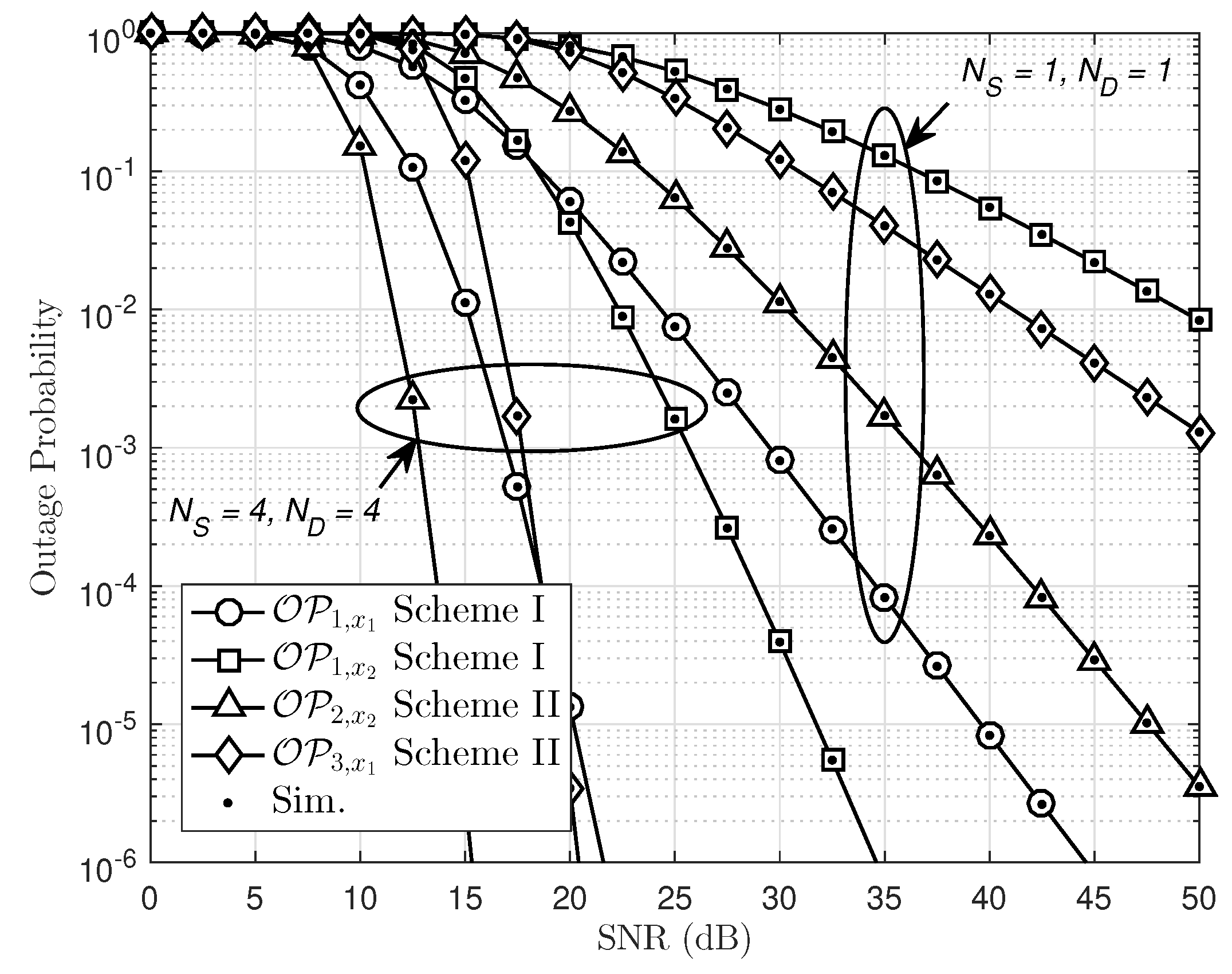
In Figure 6, we compare two schemes in terms of outage performance. The first observation is that the best outage performance at in single-antenna NOMA. The worst performance can be raised at in Scheme I as only the relay link is implemented. It can be seen clearly that outage performance at in Scheme II is better than that in Scheme I. In the case of multiple antennas assigned at the , performance of can be improved significantly. In particular, outage probability at when is the best case among the four simulated curves. It reveals that multiple antennas at the far NOMA user contribute to outage improvement.
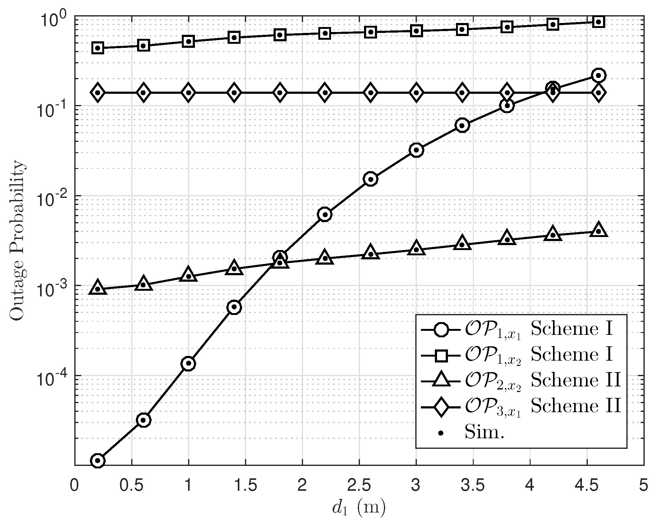
In Figure 7, we present the outage performance by varying the location of the relay . It is noted that the curve showing outage performance of only the direct link in Scheme II is not affected by varying such distance . Three users have different optimal relay locations, while outage performance of is slightly changed in the considered range of distance . The most important observation is that the outage performance of falls significantly at locating far from the . Since NOMA allocates less transmit power to the users with better channel conditions, the optimal relay location for the user with better channel conditions should be nearer to to achieve its high SNR. It confirms that optimal location arrangement plays an important role in the remaining outage performance at an acceptable level.
Next, we further examine how the time-switching factor of energy-harvesting policy affects outage performance, as in Figure 8. In this case, the special case of Scheme II, the direct link between the and is not supported by wireless power charge, and hence outage performance here is constant. Interestingly, optimal outage performance of can be seen at approximately for both schemes, while when changing time-switching factor in energy harvesting to we obtain higher power at , which can harvest wireless energy. However, the remaining time for signal processing is inversely proportion to the time allocated for energy harvesting. The main reason is that a small amount of time for energy harvesting corresponding to a larger amount of time for signal processing at the first hop causes better outage performance of , and the best case occurs at around .
In Figure 9, we present the throughput performance by varying the threshold rate . It is noted that the highest curve showing throughput performance of is in Scheme II at set values . However, throughput will be decreased at a high threshold rate. A higher number of transmit antennas at the and receive antennas at leads to improved throughput performance, and they can be affordable with higher threshold data rates. Once again, we proved that multiple antennas design leads to system performance improvement.
5. Conclusions
In this paper, we studied the impact of the number of transmit antennas at on outage performance in a multiple-antenna NOMA. In this paper, we compare two schemes related to the existence or non-existence of direct link between the and the far NOMA user. It is confirmed that optimal TAS policy deployed in this paper helps to improve performance in such a NOMA since multiple antennas lead to higher diversity order compared to single-antenna NOMA system. Simulation results revealed that the considered multiple-antenna NOMA system employing energy harvesting and a TAS scheme can achieve significantly higher performance than many situations of such systems. Furthermore, our results confirmed the robustness of the proposed scheme can be seen with respect to varying distance of these nodes, time-switching factors for energy harvesting, number of antennas at both the , and the far NOMA user. There are, intuitively, results can improve the performance of the far NOMA user, when considering and selecting various appropriate system parameters to achieve performance improvement.
Author Contributions
D.-T.D. provided idea of system, performed the theoretical analysis and wrote the manuscript. C.-B.L. implemented the simulation. M.V. contributed to the manuscript preparation.
Funding
This research was funded by VSB Technical University of Ostrava grant number SGS reg. No. SP2019/41 and the APC was funded by VSB Technical University of Ostrava.
Acknowledgments
This research received support from the grant SGS reg. No. SP2019/41 conducted at VSB Technical University of Ostrava, Czech Republic.
Conflicts of Interest
The authors declared no potential conflicts of interest with respect to the research, authorship, and/or publication of this article.
Appendix A. Proof of Lemma 1
To perform following outage probability
We first recall these SNR as , . To derive the outage probability of optimal TAS scheme, we first present the CDF of RV as as follows
It is noted that follows Chi-square distribution, we have
Then, we have expectation operation as below
Using , it can be achieved that
This is end of the proof.
Appendix B. Proof of Proposition 1
It first recalls outage event at as below
Then, it is re-expressed by
where denotes the expectation operator with respect to the RV Z. Considering on SNR follows Chi-square distribution, we have
where . Then, the second term can be formulated by
where . It is noted that recalling , then it can be obtained outage probability as
Therefore, it can be shown such outage probability as
Using , we have
References
- Islam, S.M.R.; Zeng, M.; Dobre, O.A.; Kwak, K. Performance analysis of cooperative NOMA schemes in spatially random relaying networks. IEEE Wirel. Commun. 2018, 25, 40–47. [Google Scholar] [CrossRef]
- Islam, S.M.R.; Avazov, N.; Dobre, O.A.; Kwak, K.-S. Power-Domain Non-Orthogonal Multiple Access (NOMA) in 5G Systems: Potentials and Challenges. IEEE Commun. Surv. Tutor. 2017, 19, 721–742. [Google Scholar] [CrossRef]
- Wan, D.; Wen, M.; Ji, F.; Yu, H.; Chen, F. Non-Orthogonal Multiple Access for Cooperative Communications: Challenges, Opportunities, and Trends. IEEE Wirel. Commun. 2018, 25, 109–117. [Google Scholar] [CrossRef]
- Ding, Z.; Liu, Y.; Choi, J.; Sun, Q.; Elkashlan, M.; Poor, H.V. Application of non-orthogonal multiple access in LTE and 5G networks. IEEE Commun. Mag. Technol. 2017, 55, 185–191. [Google Scholar] [CrossRef]
- Do, D.-T.; Nguyen, H.-S.; Voznak, M.; Nguyen, T.-S. Wireless powered relaying networks under imperfect channel state information: System performance and optimal policy for instantaneous rate. Radioengineering 2017, 26, 869–877. [Google Scholar] [CrossRef]
- Nguyen, X.-X.; Do, D.-T. Optimal power allocation and throughput performance of full-duplex DF relaying networks with wireless power transfer-aware channel. EURASIP J. Wirel. Commun. Netw. 2017, 2017, 152. [Google Scholar] [CrossRef]
- Nguyen, X.-X.; Do, D.-T. Maximum Harvested Energy Policy in Full-Duplex Relaying Networks with SWIPT. Int. J. Commun. Syst. 2017, 30, e3359. [Google Scholar] [CrossRef]
- Nguyen, K.-T.; Do, D.; Nguyen, X.-X.; Nguyen, N.-T.; Ha, D.-H. Wireless information and power transfer for full duplex relaying networks: Performance analysis. In Recent Advances in Electrical Engineering and Related Sciences (AETA 2015); Springer: Berlin/Heidelberg, Germany, 2015; pp. 53–62. [Google Scholar]
- Zhang, Z.; Ma, Z.; Xiao, M.; Ding, Z.; Fan, P. Full-duplex device-to-device aided cooperative non-orthogonal multiple access. IEEE Trans. Veh. Technol. 2017, 66, 4467–4471. [Google Scholar] [CrossRef]
- Liu, H.; Ding, Z.; Kim, K.J.; Kwak, K.S.; Poor, H.V. Decode-and-Forward Relaying for Cooperative NOMA Systems With Direct Links. IEEE Trans. Wirel. Commun. 2018, 17, 8077–8093. [Google Scholar] [CrossRef]
- Nguyen, T.-L.; Do, D.-T. Exploiting Impacts of Intercell Interference on SWIPT-assisted Non-orthogonal Multiple Access. Wirel. Commun. Mobile Comput. 2018, 2018, 2525492. [Google Scholar] [CrossRef]
- Do, D.-T.; Nguyen Van, M.-S.; Hoang, T.-A.; Voznak, M. NOMA-Assisted Multiple Access Scheme for IoT Deployment: Relay Selection Model and Secrecy Performance Improvement. Sensors 2019, 19, 736. [Google Scholar] [CrossRef]
- Kader, M.F.; Uddin, M.B.; Islam, S.M.R.; Shin, S.Y. Capacity and outage analysis of a dual-hop decode-and-forward relay-aided NOMA scheme. Dig. Signal Process. 2019, 88, 138–148. [Google Scholar] [CrossRef]
- Deng, D.; Fan, L.; Lei, X.; Tan, W.; Xie, D. Joint user and relay selection for cooperative NOMA networks. IEEE Access 2017, 5, 20220–20227. [Google Scholar] [CrossRef]
- Han, T.; Gong, J.; Liu, X.; Islam, S.M.R.; Li, Q.; Bai, Z.; Kwak, K.S. On Downlink NOMA in Heterogeneous Networks with Non-Uniform Small Cell Deployment. IEEE Access 2018, 6, 31099–31109. [Google Scholar] [CrossRef]
- Liu, Y.; Qin, Z.; Elkashlan, M.; Gao, Y.; Hanzo, L. Enhancing the physical layer security of non-orthogonal multiple access in large-scale networks. IEEE Trans. Wirel. Commun. 2017, 16, 1656–1672. [Google Scholar] [CrossRef]
- Do, D.-T.; Le, C. Application of NOMA in Wireless System with Wireless Power Transfer Scheme: Outage and Ergodic Capacity Performance Analysis. Sensors 2018, 18, 3501. [Google Scholar] [CrossRef]
- Nguyen, T.; Do, D. Power Allocation Schemes for Wireless Powered NOMA Systems with Imperfect CSI: System model and performance analysis. Int. J. Commun. Syst. 2018, 31, e3789. [Google Scholar] [CrossRef]
- Zaidi, S.K.; Hasan, S.F.; Gui, X. Evaluating the Ergodic Rate in SWIPT-Aided Hybrid NOMA. IEEE Commun. Lett. 2018, 22, 1870–1873. [Google Scholar] [CrossRef]
- Pei, L.; Yang, Z.; Pan, C.; Huang, W.; Chen, M.; Elkashlan, M.; Nallanathan, A. Energy-Efficient D2D Communications Underlaying NOMA-Based Networks With Energy Harvesting. IEEE Commun. Lett. 2018, 22, 914–917. [Google Scholar] [CrossRef]
- Wang, Y.; Wu, Y.; Zhou, F.; Chu, Z.; Wu, Y.; Yuan, F. Multi-Objective Resource Allocation in a NOMA Cognitive Radio Network With a Practical Non-Linear Energy Harvesting Model. IEEE Trans. Commun. 2017, 65, 1077–1091. [Google Scholar] [CrossRef]
- Hedayati, M.; Kim, I. On the Performance of NOMA in the Two-User SWIPT System. IEEE Trans. Veh. Technol. 2018, 67, 11258–11263. [Google Scholar] [CrossRef]
- Ding, Z.; Adachi, F.; Poor, H.V. The application of MIMO to non-orthogonal multiple access. IEEE Trans. Wirel. Commun. 2016, 15, 537–552. [Google Scholar] [CrossRef]
- Al-Abbasi, Z.Q.; So, D.K.C.; Tang, J. Resource allocation for MU-MIMO non-orthogonal multiple access (NOMA) system with interference alignment. In Proceedings of the 2017 IEEE International Conference on Communications (ICC), Paris, France, 21–25 May 2017; pp. 1–6. [Google Scholar]
- Wang, H.; Zhang, R.; Song, R.; Leung, S.H. A novel power minimization precoding scheme for MIMO-NOMA uplink systems. IEEE Commun. Lett. 2018, 22, 1106–1109. [Google Scholar] [CrossRef]
- Ding, Z.; Schober, R.; Poor, H.V. A general MIMO framework for NOMA downlink and uplink transmission based on signal alignment. IEEE Trans. Wirel. Commun. 2016, 15, 4438–4454. [Google Scholar] [CrossRef]
- Chen, Z.; Ding, Z.; Dai, X.; Karagiannidis, G.K. On the Application of Quasi-Degradation to MISO-NOMA Downlink. IEEE Trans. Signal Process. 2016, 64, 6174–6189. [Google Scholar] [CrossRef]
- Chen, X.; Zhang, Z.; Zhong, C.; Ng, D.W.K. Exploiting MultipleAntenna Techniques for Non-Orthogonal Multiple Access. IEEE J. Sel. Areas Commun. 2017, 35, 2207–2220. [Google Scholar] [CrossRef]
- Zhang, X.; Chen, F.; Wang, W. Outage Probability Study of Multiuser Diversity in MIMO Transmit Antenna Selection Systems. IEEE Signal Process Lett. 2007, 14, 161–164. [Google Scholar] [CrossRef]
- Lei, L.; Yuan, D.; Ho, C.K.; Sun, S. Power and Channel Allocation for Non-Orthogonal Multiple Access in 5G Systems: Tractability and Computation. IEEE Trans. Wirel. Commun. 2016, 15, 8580–8594. [Google Scholar] [CrossRef]
- Wei, Z.; Ng, D.W.K.; Yuan, J.; Wang, H.M. Optimal Resource Allocation for Power-Efficient MC-NOMA with Imperfect Channel State Information. IEEE Trans. Commun. 2017, 65, 3944–3961. [Google Scholar] [CrossRef]
- Sun, Y.; Ng, D.W.K.; Ding, Z.; Schober, R. Optimal Joint Power and Subcarrier Allocation for MC-NOMA Systems. In Proceedings of the 2016 IEEE Global Communications Conference (GLOBECOM), Washington, DC, USA, 4–8 December 2016; pp. 1–6. [Google Scholar]
- Cui, J.; Ding, Z.; Fan, P. Outage Probability Constrained MIMO-NOMA Designs Under Imperfect CSI. IEEE Trans. Wirel. Commun. 2018, 17, 8239–8255. [Google Scholar] [CrossRef]
Figure 1.
The proposed system model of NOMA facilitating multiple antennas at the and cell-edge user.
Figure 1.
The proposed system model of NOMA facilitating multiple antennas at the and cell-edge user.

Figure 2.
Outage probability of Scheme I with different numbers of transmit antennas at the , , , , and .
Figure 2.
Outage probability of Scheme I with different numbers of transmit antennas at the , , , , and .

Figure 3.
Outage probability of Scheme I with different , , , , and .

Figure 4.
Outage probability of schemes II with different number of antennas , , , , and .

Figure 5.
Outage probability of Scheme II with different , , , , and .

Figure 6.
Comparison study on outage probability between Scheme I and Scheme II with , , and .

Figure 7.
The impact of relay location on outage probability with , , dB, and .

Figure 8.
Outage probability versus the power-splitting ratio with , , dB, and .

Figure 9.
Impact of outage threshold on the throughput with transmit SNR at source , m, , , and .

© 2019 by the authors. Licensee MDPI, Basel, Switzerland. This article is an open access article distributed under the terms and conditions of the Creative Commons Attribution (CC BY) license (http://creativecommons.org/licenses/by/4.0/).
Share and Cite
MDPI and ACS Style
Le, C.-B.; Do, D.-T.; Voznak, M. Wireless-Powered Cooperative MIMO NOMA Networks: Design and Performance Improvement for Cell-Edge Users. Electronics 2019, 8, 328. https://doi.org/10.3390/electronics8030328
AMA Style
Le C-B, Do D-T, Voznak M. Wireless-Powered Cooperative MIMO NOMA Networks: Design and Performance Improvement for Cell-Edge Users. Electronics. 2019; 8(3):328. https://doi.org/10.3390/electronics8030328
Chicago/Turabian StyleLe, Chi-Bao, Dinh-Thuan Do, and Miroslav Voznak. 2019. "Wireless-Powered Cooperative MIMO NOMA Networks: Design and Performance Improvement for Cell-Edge Users" Electronics 8, no. 3: 328. https://doi.org/10.3390/electronics8030328
Note that from the first issue of 2016, this journal uses article numbers instead of page numbers. See further details here.