Monitoring of the Efficiency and Conditions of Induction Motor Operations by Smart Meter Prototype Based on a LoRa Wireless Network


Department of Electrical Engineering, University of Jaen, 23071 EPS Jaen, Spain
*
Author to whom correspondence should be addressed.
Electronics 2019, 8(9), 1040; https://doi.org/10.3390/electronics8091040
Submission received: 12 August 2019
/
Revised: 2 September 2019
/
Accepted: 12 September 2019
/
Published: 16 September 2019
(This article belongs to the Special Issue Emerging Trends in Industrial Communication)
Abstract
:The installation of smart meters in the industry to monitor induction motors (IMs) provides easy access to the measurements of the electrical and mechanical variables, which improves the installation process. Using smart meters in industry requires temporary high-resolution data to improve the energy efficiency (EE) and power factor (PF) of IMs. For these purposes, Long Range (LoRa) is an ideal wireless protocol for the usage in industries due to its low energy consumption. In addition, it provides secure communications and long range indoors and outdoors. LoRa avoids the need to install antennas or routers to extend coverage, as each gateway can service 300 LoRa devices with distances of up to 10 km. For this purpose, this research successfully developed a new prototype for a low-cost IM Efficiency Monitoring System using LoRa (IMEMSL). IMEMSL is based on the Arduino open-source electronic platform. It sends the acquired data through the LoRa low-power wide-area-network (LPWAN) and cloud access gateway. This document describes the hardware and software design and implementation. The experimental results are presented and discussed. Received Signal Strength Indicator (RSSI) and time on air measured endorse the use of LoRa for this type of meters. The approximate cost of the prototype was €72 and €93 for the versions without and with Global Positioning System (GPS), respectively.
1. Introduction
Presently, society is immersed in a deep digital transformation because of the huge advances in information and communication technologies. This digital transformation expands to the technological sector, resulting in some very interesting development possibilities. The new developed technologies include the Internet of Things (IoT), big data, cloud computing, industry 4.0 and intelligent networks.
The new concept of industry 4.0 includes both IoT structure and the local networks which are still needed to carry out real-time tasks. However, forecasts of the mass application of consumer IoT systems have stimulated the development of new wireless technologies that may also be interesting for industry. Long Range (LoRa) technology is currently investigated for the implementation of industrial wireless networks suitable for sensors and actuators of the industry 4.0 era. Using new technologies enables the system to be monitored and controlled remotely with computers and mobile devices. In this way, the measurement and monitoring of electrical and mechanicals variables is important for the study of the EE and PF of IMs in the installations. The consumption of active and reactive energy must be reduced in order to achieve energy savings.
The advantages of induction motors (IMs) make them widely used in industry. On the other hand, the progress in electronics and control techniques contribute to improving the characteristics of IMs. IMs transform a high portion of the consumed electrical energy into mechanical energy, with percentages higher than 75%. The losses represent a percentage of around 15%, which must be reduced to improve energy efficiency (EE) and make it more economical. In this sense, the evaluation and improvement of the EE and power factor (PF) of IMs is very important for industry performance using wireless technologies.
In relation to the monitoring of the IMs, [1] studied the results of an up-to-date literature survey on efficiency estimation methods of in-service motors, particularly with considerations of the motor condition monitoring requirements. In addition, [2] developed a method for in-service motor efficiency estimation based on air-gap torque using only motor terminal quantities and nameplate information, with special considerations of motor condition monitoring requirements. Furthermore, [3] realized a non-invasive method for estimating the EE of IMs used in industrial applications, which is just based on the measurement of the external field emitted by the motor.
Finally, [4] analysed the feasibility of different methods for efficiency estimation in real time, theoretically and experimentally assessing them during the operation under different operational conditions. [5] used the CEM-U/Elettronica Veneta computerized measurement unit to obtain electrical and mechanical variables such as current, voltage, power, frequency, PF and speed. This unit of measurement is connected to a PC where the data is stored.
To minimize carbon emission and energy consumption, [6] proposed a methodology for motor maintenance decision-making, starting from the efficiency monitoring and combining the results with a cost-benefit analysis. Therefore, a short review of the optimized redesign of oversized squirrel-cage IMs stator windings is presented in [7].
The researchers in [8] studied the performance of the oversized three-phase IMs which can be improved, both in terms of efficiency and PF, with a proper change of the stator winding connection, which can be delta or star, as a function of their load. Moreover, a new low-cost electronic device for automatic change of the stator winding connection for EE and PF improvement in variable-load three-phase IMs is proposed in [9].
The normative section, which includes the IEC 60034-2-1:2009 [10], is intended to establish methods to determine efficiency also to obtain specific losses. IEEE Std 112TM-2017 [11] provides the basic test procedures to evaluate the performance of a polyphase IM or generator of any size. IEC 60034_12:2016 studied the starting performance of single-speed three-phase IMs [12].
The implementation of a monitoring and control system for the IM based on PLC technology is described in [13]. Also, [14] described the process of monitored operating parameters of machine to reveal the trend of monitored characteristics to predict machine health with PLC.
To measure the physical variables of the IM in [15], an electronic circuit is developed which is located inside the motor; this circuit has an integrated wireless communications chip NRF24L01, which allows communicating with another similar module connected to a PC that collect and stores the engine data.
Different communication technologies aimed to reduce power have been proposed and deployed. It is possible to divide them into two categories: (i) low power local area networks, such as Zigbee, Wi-Fi and Bluetooth Low Energy which are typically used in short-range personal area networks; (ii) low power wide area networks, with a transmission range greater than 1000 m; this category includes LoRaWAN, Sigfox, and NB-IoT as major players.
The bibliographical revision realized for the monitoring of IMs with wireless technologies, has been elaborated on the basis of the measured parameters, wireless technology, sensors and base platform. Table 1 shows the results of the review:
Ref. [32] dealt with the discussion about using LoRa for industrial applications compared to traditional industrial wireless systems. Low power wide-area-network (LPWAN) technologies are targeting these emerging applications and markets. LPWAN is a generic term for a group of technologies that enable wide area communications at lower cost points and better power consumption are developed in [33,34]. LoRa is particularly interesting due to the openness of its higher layer specifications, LoRaWAN, and for the wide availability of low-cost devices. LoRa is also the only technology allowing the construction of private LPWAN networks [35]; recent years have seen the widespread diffusion of novel LPWAN technologies, which are gaining momentum and commercial interest as enabling technologies for the Internet of Things. Finally, [36] discussed some of the most interesting LPWAN solutions, focusing in particular on LoRa, one of the most recent and most promising technologies for the wide-area IoT.
There are some applications for LoRa such as in [37], which studies the concept of a vision system that monitors sag and temperature of overhead transmission lines using LoRa wireless communication and data transmission, the developed system consists of a camera and a microcomputer equipped with LoRa communication module. Also, [38] presented the development of relays that communicate with each other using LoRa, which allows for the combination of the cost-effectiveness and ease of wireless networks installation with long range coverage and reliability. In this way, [39] proposed a wireless low-cost solution based on LoRa technology able to communicate with remote PV power plants, covering long distances with minimum power consumption and maintenance.
This literature review [16,17,18,19,20,21,22,23,24,25,26,27,28,29,30,31] reflects the monitoring and control of IMs with different wireless technologies. In this sense, this paper proposes a low-cost prototype for EE monitoring IMs using LoRA, which has not been done before. With major shortcomings found in the prototypes proposed thus far include the following:
- The power consumption of Wi-Fi, ZigBee, Bluetooth is high compared to LoRa network, which makes it ideal for installations isolated from the electrical grid.
- To achieve a high signal strength in buildings, industrial areas, and outdoors with Wi-Fi, ZigBee and Bluetooth require a more complex installation that includes signal repeaters. LoRa is ideal for indoor and outdoor installations up to 10 km.
- Wi-Fi and Bluetooth technologies are exposed to external attacks that make them vulnerable. The LoRA network is secure.
This study develops a prototype of an accurate open-source, low-cost, IMEMSL in order to acquire electrical and mechanical variables using wireless LoRa. This prototype has an Arduino low-cost, open-source platform and is able to monitor and enhance EE and PF of IMs by measurements the electrical (v, i, p) and the mechanicals variables (T, n), performed every 0.5 s to apply YDEE algorithm. The IMEMSL is this able to monitor by wireless LoRa (125 kHz, SF=7, C/R=4/5), and stores data in the cloud using Google Sheet, every 60 s, an interval that can be configured according to the requirements. LoRa network provides IMEMSL with secure data transmission and high coverage with low energy consumption. The data stored in the cloud allows analysis of IMs by hours/days/weeks/months/years.
The Wye Delta Energy Efficiency (YDEE) algorithm determines the connection of the stator windings to improve the EE and PF in real time. To do this, firstly IMEMSL reads the electrical and mechanical variables acquired by the sensors and encoders, and the microcontroller runs the YDEE algorithm to determine the most efficient operating point of the motor at any moment.
In addition, the YDEE algorithm protects the motor against overloads that can damage it, and disconnects the motor from the electrical grid in the case of an overload. YDEE algorithm optimizes motor starting by changing the connection of the stator windings at the right time.
2. Theoretical Background
2.1. LoRA
Characteristics of LoRa are based on three basic parameters: Code Rate (CR), Spreading Factor (SF) and Bandwidth (BW). Reference [40] provided an in-depth analysis of the impact of these three parameters on the data rate and time on air, and [41] provided an in-depth analysis and assessment of LoRaWAN functional components: its capabilities (total traffic load, packet delivery quality) versus its efficiency (collision and frequency usage).
Figure 1 shows the LoRa network proposed in this research.
The LoRa radio has different configuration parameters: the carrier frequency (CF), SF, BW and CR [42,43,44,45]. The combination of these parameters provides different energy values and transmission ranges:
- CF: is the centre frequency, which used for the transmission band. For the SX1276/SX1276 transceiver, is in the range of 433 MHz in Asia, 868 MHz in Europe and 915 MHz in North America.
- SF: is the number of chips per symbol. Its value is an integer number between 6 and 12. The greater value of SF, the more capability the receiver has to move away the noise from the signal.
- BW: represents the range of frequencies in the transmission band. It can only be chosen among three options: 125 kHz, 250 kHz or 500 kHz.
- CR: The coding rate varies from 1 to 4. It denotes that every four useful bits are encoded by 5, 6, 7 or 8 transmission bits. The smaller the coding rate is, the higher the time on air is to transmit data.
The nominal bit-rate (in bits per second), is obtained taking into account these parameters. Moreover, the expression of the bit-rate is given in Equation (1):
For LoRa, the actual time on the air for a packet can be defined as the duration of uplink and downlink transmissions tpk depends on parameters of LoRa modulation such as SF, BW, CR and can be expressed as the sum of the time needed to transmit the preamble and the physical message Equation (2):
Equations (3) and (4) represent how these two terms were calculated, where Np is the number of symbols used by the radio transceiver as a physical preamble of the message and NPHY indicates the number of symbols transmitted in the physical message and can be determined as shown in Equation (6). Equation (5) defined as Tsym the duration (in seconds) of a symbol and depends on SF and BW:
To calculate the time on air (or packet duration), first have to calculate the payload symbol. For a given payload noted PL (in bytes), a spreading factor SF and a coding rate CR, the number of symbols NPHY used to transmit the payload can be calculated. CRC (cyclic redundancy check) indicates the presence (value 1) or not (value 0) of the CRC field in the physical message and DE indicates if the mechanism to prevent issues about the clock drift of the crystal reference oscillator is used (value 1 for SF12 and SF11, 0 for others).
The lower bound of the signal-to-noise ratio (SNR) at the receiver, at which it is still possible to demodulate the LoRa signal, depends on the SF; the greater the SF, the lower the signal-to-noise ratio that must be guaranteed for reliable communications.
2.2. Efficiency Energy and Power Factor of Induction Motor
EE of an electric motor represents machine behaviour during conversion of electric power into mechanical power, and is defined as: the ratio of the output power to input power expressed in the same units and usually given as a percentage [46,47]. Equation (7) of standards [10,11], obtains EE (η).
where P2 is the mechanical power in W and P1 is the electrical power in W, both with the machine running as a motor. Equation (8) defines the electrical power:
where U is the average terminal voltage in V, I is the average line current in A, and cos(φ) is the PF. In addition, P2 is determined by the Equation (9) of standards [8,11]:
where T is the torque in Nm y n is operating speed in min−1.
Direct measurements of input and output were used, as were the electrical variables in the stator and mechanical variables in the rotor shaft by the equipment are measured using the IMEMSL designed.
In an AC motor, two components of energy are present. The first component is the real power, which is converted from electrical into mechanical energy and into heat in the form of motor losses. The second, reactive power Q, is stored in the inductive elements of the machine. Electric motors contain inductive elements and, therefore, reactive energy is a consideration in selecting and applying motors in an energy-efficient manner [46,47].
PF is the ratio between the active power P and the apparent power S in an electrical load. This indicates the measure of EE of the current used to produce useful work. Reduce the PF of a system, and it operates less economically. A low PF can be the result of a significant phase difference between voltage and current at load terminals. Generally, it is the use of inductive loads such as IM that causes a current to lag behind voltage.
Therefore, if the efficiency is increased, the PF tends to decrease. To keep the PF constant, the stator current I must decrease in proportion to the increase in efficiency. To increase the PF, the stator current must be decreased more than the increasing of the efficiency.
When improving the motor performance, it is important to recognize the interdependent relationship of the efficiency and the PF. The following equation obtains the PF:
where U is the average terminal voltage in V, I is the average line current in A, P1 is the active power in W, P2 is the mechanical power in W and cos(φ) is PF.
3. IMEMSL Design
3.1. Hardware
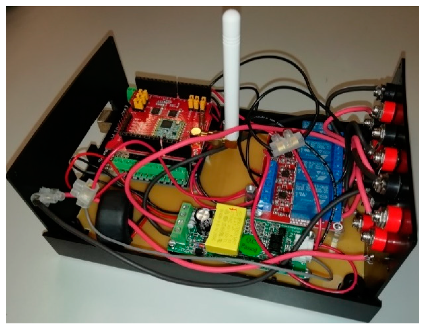
This research approaches from zero the design and the development of an IMEMSL (Figure 2) adapted to the monitoring and start-up of IM in industry 4.0 with communication via LoRa protocol and cloud storage. IMEMSL uses an AUR3 board [48] with DLS (Dragino LoRa Shield) [49] in the version without georeferencing by GPS, and AMR3 board [50] with DLGS (Dragino LoRa GPS Shield) [51] for the version with georeferencing. IMEMSL’s modular design allows making the system scalable and replace parts easily when a fault occurs, which does not affect the operation of this equipment.
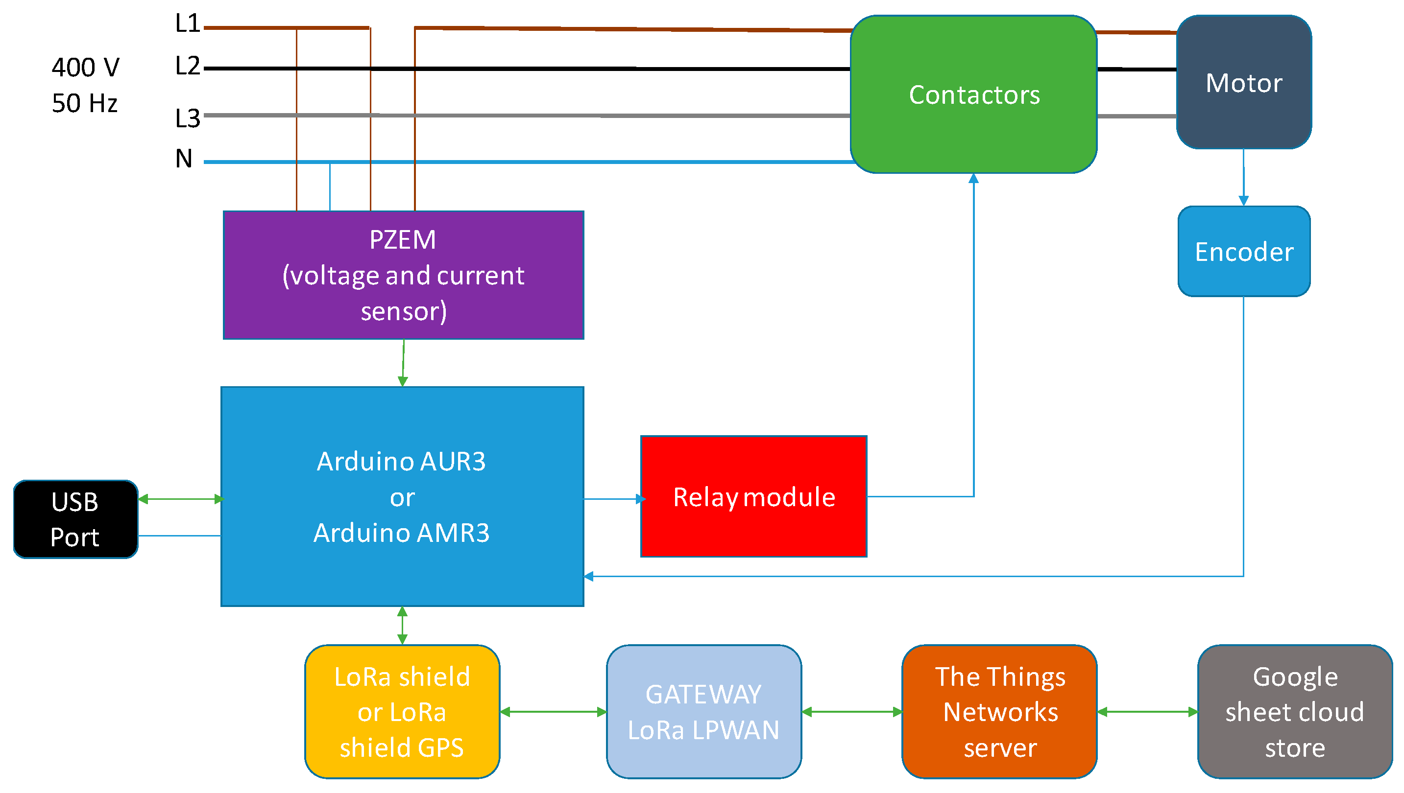
From the main components, the hardware block diagram is constructed and the other components and the relationships between them are added. Figure 3 illustrates the components and their relationships.
The version of IMEMSL with GPS uses two of the serial ports of AMR3. Serial1 for communication with GPS and Serial2 for data acquisition of electrical variables v, i and p from PZEM [52], analogic inputs A0 and A1 are reserved for the reading of T (torque) and n (speed), and digital inputs 49, 51 and 53 to activate contactors D, Y and Main, respectively.
On the other hand, the version of IMEMSL without GPS uses the serial port of AUR3 for the communication and data acquisition of PZEM, so that the electrical variables v, i and p are obtained. The variables T and n are obtained through the analogic inputs A0 and A1, and digital inputs 3, 4 and 5 to activate the contactors D, Y and Main, respectively.
Figure 4 shows the wiring diagram of IMEMSL in its two versions. IMEMSL is powered by an external 230 V 50 Hz power supply, with output in the range of 7–12 V DC, which is accepted by the AUR3 and AMR3 boards.
To obtain the cost of IMEMSL, Table 2 and Table 3 show the cost of the components, which is much reduced, which is very interesting for installation in IM monitoring in industry.
Table 4 shows the cost of the gateways available from the brand Dragino, which in this research used OLG02 for the outdoor type and LG01-N for the indoor.
3.1.1. Microcontroller
A microcontroller is a small computer on a single integrated circuit containing a processor core, memory, and programmable input/output peripherals. These components are used for residential and industrial devices due the capability for manage control signals and devices.
In this paper, the main control component for IMEMSL without GPS is an AUR3 [48] development board with ATmega328P, and IMEMSL with GPS using an AMR3 development board with ATmega2560 [50]. Both microcontrollers use a platform for open-source electronic prototypes. The main characteristics of microcontrollers are [48] and [50].
IMEMSL version without GPS does not need serial ports for communication with the PZEM, therefore AUR3 is used. In contrast, IMEMSL version with GPS uses the AMR3, as it needs two serial ports, one for the GPS and one for the PZEM.
3.1.2. Wireless Communication Access. LoRa Shield
There are different options for integrating LoRa in systems that work with the measurement of electrical variables, among which we can highlight: (i) Arduino MKR WAN 1300 [53]; (ii) Monteino [54]; (iii) Lopy4 [55]; (iv) Libelium [56]; (v) Dragino [57]. LoRa components used abd abakyed in each equipment are:
- (iii), (iv) and (v) use LoRa chips from the Semtech brand.
- (iii) and (v) use the SX1276/SX1278 chip.
- (iv) uses model SX1272.
- (i) uses the chip CMWX1ZZABZ from Murata.
- Finally, (ii) uses the HOPERF Electronics chip RFM95/96/97/98.
All platforms have similar features. The decision to use one or other depends on added values (benefits). The option chosen is Dragino, which uses the Arduino platform, and gives it great versatility due to the multitude of equipment that could be complemented with the LoRa system, for example positioning with GPS, reading of electrical and mechanical variables included in the prototype. Another great advantage is that it is easy to program using Arduino environment, which is an open development environment and allows any researcher to reproduce the proposed system.
Also, (v) is complemented with indoor and outdoor gateways that give access to IoT and cloud computing, so that they constitute a global solution for a complete data acquisition system in the industry or housing.
The core of DLS [49] is the LoRa SX1276/SX1278 chip [58], oriented to professional environments of networks where sensors are integrated, among which can be found irrigation systems, intelligent cities and homes, smart meters, smart phone detection, automation of buildings and industries, etc.
DLS makes it possible to send data over long distances with low data rates. On the other hand, it has minimal power consumption due to the use of the ultra-long range widened spectrum, coupled with high immunity to interference. The characteristics summarizes of DLS are in [49].
3.1.3. Wireless Communication Access. LoRa GPS Shield
The chosen manufacturer has available a shield that complements the communications based on LoRa system with a GPS system that allows georeferencing the monitored equipment. This added feature provides great versatility to the system.
The base of the LoRa system uses the same chip as DLS in point 3.1.2. As for the GPS system, the manufacturer has chosen the MTK MT3339 chip [59]; the chosen manufacturer provided a shield that complements the communications based on the LoRa system with a GPS system that allows georeferencing the monitored equipment. This added feature provides great versatility to the system.
The base of the LoRa system uses the same chip as DLS in point 3.1.2. As for the GPS system, the manufacturer has chosen the MTK MT3339 chip. The features of DLGS are in [51].
3.1.4. Wireless Communication Access. LoRa IoT Gateway
The Dragino System manufactures LoRa IoT indoor gateways (LG0 family [60]) and outdoor (OLG0 family [61]) with single and double channels, and with Wi-Fi, Ethernet, 3G or 4G communication, which gives it high versatility in connection with IoT.
Each of these gateways integrates between 50 and 300 LoRa devices, such as DLS and DLGS. It supports the LoRaWAN protocol with simple frequency and customized LoRa transmission protocol. The LoRa system is realized with one or two sx1276/sx1278 chips [58], to work in simplex or duplex mode to increase communication efficiency. The gateway is controlled by adapted Linux.
For the access to the IoT services there are available such as MQTT (Message Queue Telemetry Transport) [62], TTN (The Things Network) [63], LoRa repeater mode, TCP/IP client and TCP/IP server, so that it can be adapted to a wide range of possibilities and configurations according to the developed prototype. The characteristics of IoT gateways are in [60,61].
The configuration parameters of the LoRa network are:
- SF: 7.
- BW: 125 kHz.
- CR: 4/5.
- SNR: 7.8.
- TX: 868.1 MHz (Europe).
- RX: 868.1 MHz (Europe).
- Activation method: OTAA.
3.1.5. Electric Power Meter
Voltage and current sensors are available in the market in various forms and operating principles. In this sense, current sensors can be invasive or non-invasive, invasive require modification of the electrical installation to be monitored. Techniques such as the Hall effect or current transformers are used, and both techniques transform the signal from the electric current to a proportional voltage.
An example of an invasive sensor is the ACS712 model [64], and as a non-invasive model STC-013 by YHDC [65].
There are several options available for the voltage sensor: (i) 230/12 or 24 V transformer, AC/DC rectifier and voltage divider; (ii) 230/24 V transformer, AC/DC rectifier and FZ0430 meter; (iii) ZMPT101b voltage transformer from 230 to 5V.
These sensors measure instantaneous values, so it is necessary to perform the process of calculating the RMS, v, i, p, q and PF values. PZEM-004t can be used to measure the RMS of v, i and p in a single sensor [52], as is chosen in this investigation. In the paper [66], the authors developed and successfully calibrated a new prototype for an accurate low-cost on-time single-phase power smart meter and is based on the Arduino open-source electronic platform.
Electric motors, more specifically those of the three-phase asynchronous family, both in the squirrel cage and in the wounded rotor, are electric receivers almost completely balanced in the three phases. In this way, with the reading of the electrical variables of a single phase, obtaining the data for the three phases is easy, as is well-known in the electrical theory.
For this reason, this equipment was used as a single meter to prevent the increasing in the price of the set. It is possible to implement a meter for each phase the connection is quite simple. PZEM-004t characteristics are in [52].
3.2. Software Design
3.2.1. Microcontroller Program
The microcontroller chosen in each version of IMEMSL AUR3 or AMR3 must obtain the electrical variables, send them to LoRa for upload to the cloud, and read data from LoRa to execute some IM drive command.
The first phase of the program consists of initializing the system, which includes (i) preparing the serial ports for communications; (ii) initializing PZEM to read electrical variables; (iii) setting the digital inputs/outputs to drive the contactor coils in output mode. Moreover, the system initialization process is only carried out when the system is started or reset. Continuously the microcontroller must perform the tasks of reading data from LoRa LPWAN, and reading electrical variables and sending them to LoRa LPWAN, to finish with the connection routine and return to the beginning of the loop. Figure 5 shows the main program block diagram.
LoRa communication is bi-directional. As shown Figure 5, the main program reads data from the cloud and executes the command to start or stop the IM when it is received. Through the LoRa network the data obtained by the sensors are sent to the cloud.
The read and write subroutines are quite simple and do not make it necessary to make the specific flowchart. On the contrary, the connection subroutine is somewhat more complex and its block diagram is shown in Figure 6 below.
The automatic mode operation of IMEMSL shown in Figure 5 executes the optimization algorithm described below, whose block diagram is reflected in Figure 7.
The restrictions of the problem are: (i) speed; (ii) slip; (iii) current. The objectives of YDEE optimization algorithm are developed in [8,9]: (i) improve EE of the IMs; (ii) raise the PF.
Moreover, the algorithm starts the process by verifying if the current of the motor exceeds the overload value indicated by the maximum current of the IM in D by the overload factor k. This action protects the motor against excessive over currents which damage the motor and may destroy it. If the overload is excessive, the motor stops immediately in less than 1 s. Otherwise, the algorithm starts to optimize.
The first phase calculates the EE of the motor in Y and D, testing which of both EEs is greater. If the highest EE is that of D and IM is operating in Y, it has to change to D. In contrast, if the highest EE is Y, check the restrictions of the problem: (i) maximum current on Y; (i) speed equal to or greater than that of the process; (iii) slip greater than nominal. If any of these restrictions are not satisfied, the motor must immediately switch to connection D.
3.2.2. LoRa Wireless Communication
LoRa DLS and DLGS devices communicate with IoT and cloud computing via gateways implemented with various protocols such as those described in 3.1.4. Among them, TTN was chosen as the link gateway to cloud computing.
The payload used uses the Cayenne format, one of those used by TTN. The length of the payload is 23 bytes organized as follows:
- Bytes 0 to 3: Byte 0 indicates the channel, #1 for the voltage, byte 1 indicates the type of data, float with a decimal and bytes 2 and 3 contain the measured voltage data.
- Bytes 4 to 7: Byte 4 indicates the channel, #2 for the current, byte 5 indicates the type of data, float with a decimal and bytes 6 and 7 contain the measured current data.
- Bytes 8 to 11: Byte 8 indicates the channel, #3 for power, byte 9 indicates the type of data, float with a decimal and bytes 10 and 11 contain the measured power data.
- Bytes 12 to 22: Byte 12 indicates the channel, #4 for the GPS position, byte 13 indicates the type of data, GPS location, bytes 14, 15 and 16 contain the latitude with a float with four decimal places, bytes 17, 18 and 19 contain the longitude with a float with four decimal places and bytes 20, 21 and 22 contain the longitude with a float with two decimal places.
Figure 8 shows a screenshot of the data upload from the OLG02 gateway used.
Then the HTTP integration extension is added to include a web address, in this case that of a Google Sheet document where you want to store information in real time. Different integrations and storage possibilities are possible. The results section shows how your data is stored in Google Sheets.
Equipment does not support the power of the motor, since it only controls the coil of the contactor; it is, therefore, very feasible to realize in reduced size and price.
4. Result and Discussion
4.1. Test Equipment
4.1.1. Test Machines
The case studies are made in the electrical machinery laboratory of the Electrical Engineering Department of the University of Jaen. In this laboratory, there are several trainers of electrical machines of the Lucas-Nulle, in the power range of 0.3 kW. Laboratory has other machines of 1.5, 2.2 and 3.0 kW.
4.1.2. Used Machines
Four squirrel cage machines of different powers are used to analyse the behaviour of the prototype developed, within a range of powers applicable in the industry. Table 5 illustrates the characteristics of the machines used.
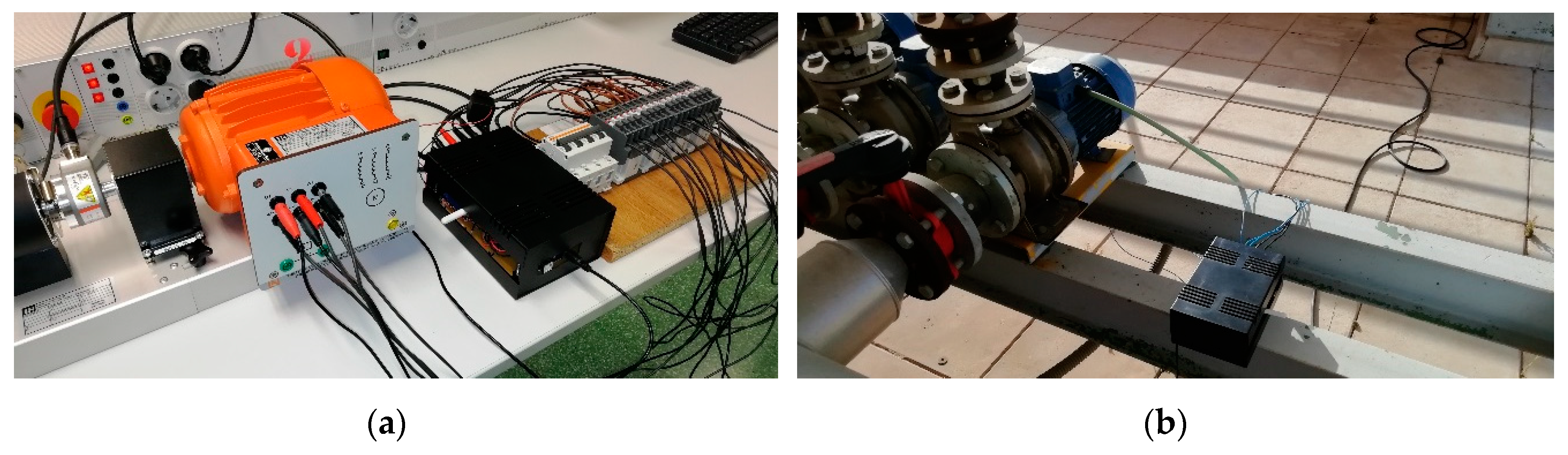
Figure 9 shows the test assemblies made.
The equipment used are IMEMSL with GPS, they are located in the Higher Polytechnic School of Jaén, in different laboratories, high voltage laboratory located in the ground floor, machines electric laboratory and electrical installations laboratory located on the 2nd floor and the terrace of the building located on the 5th floor. Table 6 shows the location of the IMEMSLs. GW is located in the laboratory of electrical machines, where it centralized the data collection and connection of the GW to the Internet.
4.2. LoRa System
This section reflects the operation of the LoRa LPWAN network. The measurements taken indicate the signal strength, the time on air of the messages sent and the ratio of packets lost, during the tests carried out in a week. The electrical (v, i, p, q, PF) and mechanical (T, n) variables measured with IMEMSLs in the same time period are also shown.
Figure 10a shows the signal strength of each piece of equipment installed. It can be observed that the highest RSSI corresponds to IMEMSL #2, because it is located closer to the gateway. In contrast, the lowest RSSI is that of IMEMSL #4, which is located at the furthest point from the gateway.
The average times (Figure 10b) for sending information in the time on air are between 30 and 40 ms, with a maximum point value of 105 ms. This indicates that data transmission times from LoRa devices to the gateway are quite fast.
The average packet loss ratio is between 15 and 30%, with IMEMSL #4 having the lowest loss level and IMEMSL #1 the highest, as shown in Figure 10c. IMEMSL #4 has a 100% loss during the first 12 minutes of the test due to inclement weather.
Table 7 shows average values of the descriptive statistics describing subsets of indoor/outdoor to RSSI, time on air and packet loss rate.
Table 7 illustrates the mean values μ, standard deviation σ of RSSI, Time on air and Packet loss rate. μRSSI is around 95% for IMEMSL #1, #3 and #4. IMEMSL #2 has around 57% of μRSSI, due to the location of the equipment in the building. The average times of transmission in the air are very similar, around 37 ms, because the PayLoad has the same length of 23 bytes for all IMEMSL. σPLR for IMEMSL #4 is high because in the first 12 minutes are lost 100% of the packets by weather disturbances.
Table 8 illustrates packet send, delivery, loss and the average time between packet. The packets sent are 10080 for all IMEMSL. Table 7 shows that the ratio of packets delivered is above 71%, which represents a high efficiency in data transmission, with losses below 30%. Considering that the packet sending time is each 60 s, the maximum time between packets is 84.05 s, which represents a maximum increase of 40% over the packet sending time.
Figure 11 shows the data acquired with IMEMSLs electrical and mechanical sensors and transmitted by LoRa devices to the gateway and then uploaded to the cloud, specifically to Google Sheets for each of the 4 IMEMSL used in the tests.
4.3. Weekly Study of IMs
In this section, the operation of the motors is analysed in a practical, in operation cycles with constant torque, from the data stored in Google Sheet.
The equipment uses the percentage of load obtained by measuring the electrical and mechanical variables, in each instant of the engine operation to apply YDEE algorithm of optimization in real time, and to upload data to the Cloud every 60 s. Figure 12 and Figure 13 show the analysis of EE, active and reactive power in the stator, load factor (LF) and PF for motors of 0.37 and 2.2 kW during one week.
Figure 12a and Figure 13a show the areas where the EE is greater in Y than in D. The equipment developed applying YDEE algorithm described in point 3.2.1 changes the connection to Y, in the rest of the zones, it connects the motor in D, optimizing the operation of the motor in real time. Figure 12c and Figure 13c show the LF at each instant.
4.4. Energy Saving Analysis of IM
This section studies the energy savings of an industry case study, with operating intervals at constant torque loads.
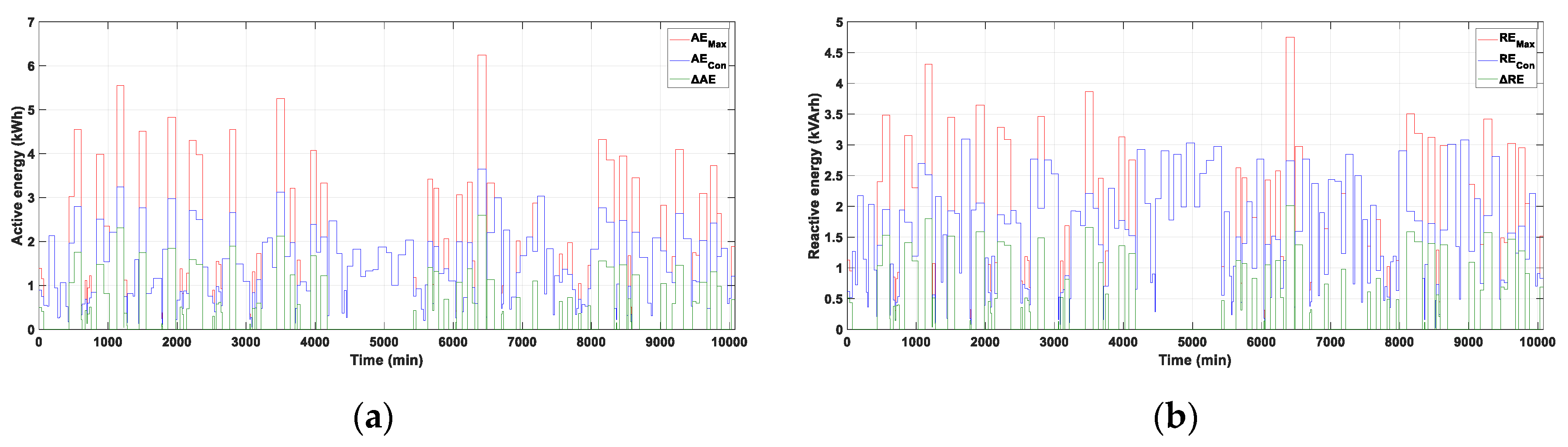
The maximum active energy AEmax, used as the basis for the energy savings is that consumed by the motor connected to the stator windings in D, in continuous operation. The active energy consumed AEcon reflects the energy demanded by the electrical network motor by applying YDEE optimization algorithm implemented in IMEMSL in real time. ΔAE shows the energy savings, i.e., the difference between the AEmax and AEcon. REmax, REcon and ΔRE are the equivalents for reactive powers. Figure 14a and Figure 15a shows AEmax, AEcon and ΔAE for the 1.5 and 3.0 kW IM during seven days of operation in the industry. Figure 14a and Figure 15b is similar for RE.
Table 9 illustrates the calculated energy savings during the study period using YDEE algorithm, obtaining the maximum and consume active and reactive energies for each IMEMSLs. For the period analysed, 4 IMEMSLs have AEsav of 139.73 kWh, and have REsav of 139.75 kVArh. The LoRa system does not contribute to the energy savings of IMs. The proposed YDEE algorithm performs IMs optimization and achieves EE.
4.5. Cloud Storage
Finally, this section shows the result of data uploading to the cloud from LoRa devices to the gateway, which uploads them to TTN, which acts as a link to Google Sheets where they are stored with the programmed cadence of 60 s.
Figure 16 illustrates the graphs of the stored electrical and mechanical variables.
5. Conclusions
This research study successfully developed a new prototype IMEMSL for monitoring electrical and mechanical variables, upload data to cloud using wireless LoRa and improve EE and PF using the YDEE algorithm, determining the optimal point of operation. This IMEMSL was based on the Arduino open-source electronic platform. Input data were collected with a set of sensors connected with Arduino. As a novelty, the application of LoRa communication technology allows the transmission of data to a remote gateway, to evaluate the performance of IMs in real time.
From the results obtained, it can be deduced that factors such as the distance between origin and destination, the line of sight between origin and destination, and propagation problems have a decisive influence on the appropriate data reception process. The RSSI is between -58 and -98 dBm depending on the distance to the gateway, within the range of the LoRa transmission limits. On the other hand, the rate of packets delivered is between 71 and 82 % of those sent. In addition, the average airtime of each send is 37 ms. This indicates that the LoRa Wireless system supports its use in this prototype.
The YDEE algorithm determines the connection of the stator windings to improve the EE and PF in real time. The algorithm developed works continuously as long as the equipment is connected independently of the data upload to the cloud. During the monitored time, the active energy consumption was reduced by 139.73 kWh and the reactive energy consumption by 139.75 kVAr with the designed equipment.
Data stored in the cloud allows analysis of IMs and optimize their performance. The installed gateway collects data from LoRa devices, allowing a maximum of 300 devices to be connected, sends them to TTN and finally uploads them to Google Sheet.
Industry 4.0 is based on the use of sensors and actuators to optimize the production process. The LPWAN wireless network, with low energy consumption, without cables and lower costs, allows monitoring IMs and improve their EE and PF. The advantage of the LoRa network is that it can be used in facilities without the need for a Wi-Fi network and with coverage of up to 10 km outdoors, in addition to positioning the IMs using GPS.
This paper describes the hardware and software designed and implemented. The results obtained justify IMEMSL with the LoRa system, which is not currently used in IM monitoring. In addition to this, the system has an approximate low-cost of only €72 or €93, without or with the GPS system, respectively.
Our proposed solution thus offers an alternative system to be implemented in industries with IMs in order to monitor and optimize their operation.
Author Contributions
All authors have contributed actively and fundamentally to the development of the presented work. and A.C.-O. and F.S.-S. have developed the hardware and software design, assembled the prototypes and have designed and carried out the tests. The writing of the paper has been done by each author attending to their corresponding part of the development of the work.
Acknowledgments
The authors would like to thank the Department of Electrical Engineering of the University of Jaén, for allowing the use of their laboratories and material in the development of this research.
Conflicts of Interest
The authors declare no conflict of interest.
Abbreviations
The following abbreviations are used in this manuscript:
| AE | Active energy |
| AMR3 | Arduino Mega R3 |
| AUR3 | Arduino Uno R3 |
| BW | Bandwidth |
| CF | Carrier Frequency |
| CR | Code Rate |
| CRC | Cyclic Redundancy Check |
| D | Delta connection |
| DLS | Dragino LoRa Shield |
| DLGS | Dragino LoRa GPS Shield |
| EE | Energy efficiency |
| GPS | Global Positioning System |
| GW | Gateway |
| i | Current |
| I | Line current |
| IM | Induction Motor |
| IMEMSL | Induction Motor Efficiency Monitoring System using LoRa |
| IoT | Internet of Things |
| k | Overload factor |
| LoRa | Long Range |
| LoRaWAN | Long Range Wide Area Network |
| LPWAN | Low Power Wide Area Network |
| MQQT | Message Queue Telemetry Transport |
| n | Speed |
| N | Number |
| NB-IoT | Narrowband Internet of Things |
| p | Active power |
| P1 | Stator active power |
| P2 | Power mechanical in shaft |
| PF | Power factor |
| PLC | Programmable Logic Controller |
| PZEM | PZEM-004t |
| RE | Reactive Energy |
| RSSI | Received Signal Strength Indicator |
| RMS | Root means square |
| SF | Spreading Factor |
| SNR | Signal-to-Noise Ratio |
| t | Time |
| T | Torque |
| TTN | The Things Network |
| U | Line voltage |
| v | Voltage |
| Y | Wye connection |
| YDEE | Wye Delta Energy Efficiency |
| Wi-Fi | Wireless Fidelity |
| WNS | Wireless Sensor Networks |
| Greek symbols | |
| µ | mean |
| σ | standard deviation |
| ϕ | phase angle of current |
| Subscripts | |
| con | consumed |
| max | maximum |
| min | minimum |
| p | preamble |
| PHY | symbols transmitted in the physical message |
| pk | packet |
| sav | saved |
| sym | symbol |
References
- Lu, B.; Habetler, T.G.; Harley, R.G. A survey of efficiency-estimation methods for in-service induction motors. IEEE Trans. Ind. Appl. 2006, 42, 924–933. [Google Scholar] [CrossRef]
- Lu, B.; Habetler, T.G.; Harley, R.G. A nonintrusive and in-service motor-efficiency estimation method using air-gap torque with considerations of condition monitoring. IEEE Trans. Ind. Appl. 2008, 44, 1666–1674. [Google Scholar] [CrossRef]
- Zidat, F.; Lecointe, J.-P.; Morganti, F.; Brudny, J.-F.; Jacq, T.; Streiff, F. Non Invasive Sensors for Monitoring the Efficiency of AC Electrical Rotating Machines. Sensors 2010, 10, 7874–7895. [Google Scholar] [CrossRef] [PubMed] [Green Version]
- Sousa Santos, V.; Cabello Eras, J.J.; Sagastume Gutierrez, A.; Cabello Ulloa, M.J. Assessment of the energy efficiency estimation methods on induction motors considering real-time monitoring. Measurement 2019, 136, 237–247. [Google Scholar] [CrossRef]
- Singh, G.; Kumar, T.A.; Naikan, V. Efficiency monitoring as a strategy for cost effective maintenance of induction motors for minimizing carbon emission and energy consumption. Reliab. Eng. Syst. Saf. 2019, 184, 193–201. [Google Scholar] [CrossRef]
- Ferreira, F.J.T.E.; De Almeida, A.T. Induction motor downsizing as a low-cost strategy to save energy. J. Clean. Prod. 2012, 24, 117–131. [Google Scholar] [CrossRef]
- Fernandes, J.D.; Souza, F.E.C.; Maniçoba, G.G.C.; Salazar, A.O.; De Paiva, J.A. Wireless Monitoring of Induction Machine Rotor Physical Variables. Sensors 2017, 17, 2660. [Google Scholar] [CrossRef]
- Ferreira, F.J.T.E.; De Almeida, A. Method for in-field evaluation of the stator winding connection of three-phase induction motors to maximize efficiency and power factor. IEEE Trans. Energy Convers. 2006, 21, 370–379. [Google Scholar] [CrossRef]
- Ferreira, F.J.T.E.; Almeida, A.T.; Baoming, G.; Faria, S.P.; Marques, J.M. Automatic Change of the Stator-Winding Connection of Variable-Load Three-Phase Induction Motors to Improve the Efficiency and Power Factor. In Proceedings of the IEEE International Conference on Industrial Technology, Hong Kong, China, 14–17 December 2005. [Google Scholar] [CrossRef]
- International Electrotechnical Commission. Rotating Electrical Machines—Part 2-1: Standard Methods for Determining Losses and Efficiency from Tests (Excluding Machines for Traction Vehicles); IEC 60034-2-1:2014; International Electrotechnical Commission: Geneva, Switzerland, 2014. [Google Scholar]
- IEEE. IEEE Standard Test Procedure for Polyphase Induction Motors and Generators; IEEE Std. 112TM-2017; IEEE: New York, NY, USA, 2017. [Google Scholar]
- International Electrotechnical Commission. Rotating Electrical Machines—Part 12: Starting Performance of Single-Speed Three-Phase Cage Induction Motors; IEC 60034-12 Standard; Edition 3.0 2016-11; International Electrotechnical Commission: Geneva, Switzerland, 2016. [Google Scholar]
- Ioannides, M. Design and Implementation of PLC-Based Monitoring Control System for Induction Motor. IEEE Trans. Energy Convers. 2004, 19, 469–476. [Google Scholar] [CrossRef]
- Irfan, M.; Saad, N.; Ibrahim, R.; Asirvadam, V. Development of an intelligent condition monitoring. In Proceedings of the IEEE Business Engineering and Industrial Applications Colloquium (BEIAC), Kuala Lumpur, Malaysia, 7–9 April 2013. [Google Scholar] [CrossRef]
- Al-Senaidi, S.; Alolah, A.I.; Alkanhal, M.A. Magnetization-Dependent Core-Loss Model in a Three-Phase Self-Excited Induction Generator. Energies 2018, 11, 3228. [Google Scholar] [CrossRef]
- Şen, M.; Kul, B. IoT-Based Wireless Induction Motor Monitoring. In Proceedings of the XXVI International Scientific Conference Electronics (ET), Sozopol, Bulgaria, 13–15 September 2017. [Google Scholar] [CrossRef]
- Kunthong, J.; Sapaklom, T.; Konghirun, M.; Prapanavarat, C.; Ayudhya, P.N.N.; Mujjalinvimut, E.; Boonjeed, S. IoT-Based Traction Motor Drive Condition Monitoring in Electric Vehicles: Part 1. In Proceedings of the IEEE 12th International Conference on Power Electronics and Drive Systems (PEDS), Honolulu, HI, USA, 12–15 December 2017. [Google Scholar] [CrossRef]
- Brahim, S.B.; Bouallegue, R.; David, J.; Vuong, T.H. Wireless Communication to monitor the Rotating Electrical Machines. In Proceedings of the 23rd International Conference on Software, Telecommunications and Computer Networks (SoftCOM), Split, Croatia, 16–18 September 2015. [Google Scholar]
- Cano-Ortega, A.; Sánchez-Sutil, F.J.; Hernández, J.C. Power Factor Compensation using Teaching Learning Based Optimization and Monitoring System by Cloud Data Logger. Sensors 2019, 19, 2172. [Google Scholar] [CrossRef]
- de Carvalho, D.P.; Silva, F.B.; Vanço, W.E.; da Silva Gonçalves, F.A.; Bissochi, C.A., Jr.; Monteiro, R.V.; Guimarães, G.C.; de Andrade, D.A. A method for real-time wireless monitoring of the efficiency and conditions of three-phase induction motor operation. Electric Power Syst. Res. 2018, 157, 70–82. [Google Scholar] [CrossRef]
- Bin, L.; Gungor, V.C. Online and Remote Motor Energy Monitoring and Fault Diagnostics Using Wireless Sensor Networks. IEEE Trans. Ind. Electron. 2009, 56, 11. [Google Scholar] [CrossRef]
- Khairnar, V.C.; Sandeep, K. Induction Motor Parameter Monitoring System using Zig Bee Protocol & MATLAB GUI, Fourth International Conference on Advances in Electrical. In Proceedings of the Electronics, Information, Communication and Bio-Informatics (AEEICB), Chennai, India, 27–28 February 2018. [Google Scholar] [CrossRef]
- Sridhar, S.; Uma Rao, K.; Nihaal, M.S.; Hetty Aashik, A.K. Real Time Wireless Condition Monitoring of Induction Motor. In Proceedings of the IEEE Industrial Electronics and Applications Conference (IEACon), Kota Kinabalu, Malaysia, 20–22 November 2016. [Google Scholar] [CrossRef]
- Sridhar, S.; Uma Rao, K.; Shetty Aashik, A.K.; Nihaal, M.S. Wireless monitoring of power quality disturbances in the supply to induction motor. In Proceedings of the IEEE 7th Power India International Conference (PIICON), Bikaner, India, 25–27 November 2016. [Google Scholar] [CrossRef]
- Arun Nadh, A.; Lakshmi Praba, N. Automatic speed and torque monitoring in induction motors using ZigBee and SMS. In Proceedings of the IEEE International Conference ON Emerging Trends in Computing, Communication and Nanotechnology (ICECCN), Irunelveli, India, 25–26 March 2013. [Google Scholar] [CrossRef]
- Ishtiaque Hossain, N.; Sakib Reza, M.; VibNet, A. Application of Wireless Sensor Network for Vibration Monitoring Using ARM, International Conference on Robotics. In Proceedings of the Electrical and Signal Processing Techniques (ICREST), Dhaka, Bangladesh, 10–12 January 2019. [Google Scholar] [CrossRef]
- Patil, R.R.; Date, T.N.; Kushare, B.E. ZigBee Based Parameters Monitoring System for Induction Motor. In Proceedings of the IEEE Students’ Conference on Electrical, Electronics and Computer Science, Bhopal, India, 1–2 March 2014. [Google Scholar] [CrossRef]
- Mahendra, P.; Bodkhe, P.; Pawar, K.N. Parameter Monitoring Using Zigbee Protocol for Three Phase Induction Motor. Int. J. Emerg. Technol. Adv. Eng. 2014, 4, 1. [Google Scholar]
- Jingtao, H. In-Service Motor Monitoring and Energy Management System Based on Wireless Sensor Networks. In Proceedings of the International Conference on Electrical Machines and Systems, Wuhan, China, 17–20 October 2008. [Google Scholar]
- Yaman, O.; Aydın, İ.; Karaköse, M.; Akın, E. Wireless Sensor Network Based Fault Diagnosis Approaches. In Proceedings of the 21st Signal Processing and Communications Applications Conference (SIU), Haspolat, Turkey, 24–26 April 2013. [Google Scholar] [CrossRef]
- Hou, L.; Bergmann, N.W. Novel Industrial Wireless Sensor Networks for Machine Condition Monitoring and Fault Diagnosis. IEEE Trans. Meas. 2012, 61, 10. [Google Scholar] [CrossRef]
- Rizzi, M.; Ferrari, P.; Flammini, A.; Sisinni, E.; Gidlund, M. Using LoRa for industrial wireless networks. In Proceedings of the IEEE 13th International Workshop on Factory Communication Systems (WFCS), Trondheim, Norway, 31 May–1 June 2017. [Google Scholar] [CrossRef]
- LoRa Alliance. Available online: https://lora-alliance.org (accessed on 30 July 2019).
- LoRa Alliance. LPWA Technologies Unlock New IoT Market Potential, Machina Research. 2015. Available online: https://www.lora-alliance.org/portals/0/documents/whitepapers/LoRa-Alliance-Whitepaper-LPWA-Technologies.pdf (accessed on 30 July 2019).
- Vangleista, L.; Zanella, A.; Zorzi, M. Long-Range IoT Technologies: The Dawn of LoRa, Future ACCESS Enablers of Ubiquitous and Intelligent Infrastructures; Springer: Berlin/Heidelberg, Germany, 2015; pp. 51–58. [Google Scholar]
- De Carvalho Silva, J.; Rodrigues, J.J.P.C.; Alberti, A.M.; Solic, P.; Aquino, A.L.L. LoRaWAN—A Low Power WAN Protocol for Internet of Things: A Review and Opportunities. In Proceedings of the 2nd International Multidisciplinary Conference on Computer and Energy Science (SpliTech), Split, Croatia, 12–14 July 2017. [Google Scholar]
- Wydra, M.; Kubaczynski, P.; Mazur, K.; Ksiezopolski, B. Time-Aware Monitoring of Overhead Transmission Line Sag and Temperature with LoRa Communication. Energies 2019, 12, 505. [Google Scholar] [CrossRef]
- Angrisani, L.; Bonavolontà, F.; Liccardo, A.; Schiano, R. On the Use of LoRa Technology for Logic Selectivity in MV Distribution Networks. Energies 2018, 11, 3079. [Google Scholar] [CrossRef]
- Paredes-Parra, J.M.; García-Sánchez, A.J.; Mateo-Aroca, A.; Molina-García, A. An Alternative Internet-of-Things Solution Based on LoRa for PV Power Plants: Data Monitoring and Management. Energies 2019, 12, 881. [Google Scholar] [CrossRef]
- Noreen, U.; Bounceur, A.; Clavier, L. A Study of LoRa Low Power and Wide Area Network Technology. In Proceedings of the International Conference on Advanced Technologies for Signal and Image Processing (ATSIP), Fez, Morocco, 22–24 May 2017. [Google Scholar] [CrossRef]
- Phung, K.H.; Tran, H.; Nguyen, Q.; Huong, T.T.; Nguyen, T.L. Analysis and Assessment of LoRaWAN. In Proceedings of the 2nd International Conference on Recent Advances in Signal Processing, Telecommunications & Computing (SigTelCom), Ho Chi Minh City, Vietnam, 29–31 January 2018. [Google Scholar] [CrossRef]
- Bouguera, T.; Diouris, J.F.; Chaillout, J.J.; Jaouadi, R.; Andrieux, G. Energy Consumption Model for Sensor Nodes Based on LoRa and LoRaWAN. Sensors 2018, 18, 2104. [Google Scholar] [CrossRef]
- Polonelli, T.; Brunelli, D.; Marzocchi, A.; Benini, L. Slotted ALOHA on LoRaWAN-Design, Analysis, and Deployment. Sensors 2019, 19, 838. [Google Scholar] [CrossRef]
- Sornin, N.; Yegin, A. LoRaWANTM 1.1 Specification. 2017. Available online: https://lora-alliance.org/sites/default/files/2018-04/lorawantm_specification_-v1.1.pdf (accessed on 29 July 2019).
- LoRa Alliance Technical Committee Regional Parameters Workgroup. LoRaWANTM 1.1 Regional Parameters. 2018. Available online: https://lora-alliance.org/sites/default/files/2018-04/lorawantm_regional_parameters_v1.1rb_-_final.pdf (accessed on 29 July 2019).
- Jordan, H.E. Energy-Efficient Electric Motors and Their Applications, 2nd ed.; Springer Science: Berlin, Germany, 1994. [Google Scholar]
- Emadi, A. Energy-Efficient Electric Motors, 3th ed.; CRC Press: Boca Raton, FL, USA, 2004. [Google Scholar]
- Arduino Home. Available online: https://store.arduino.cc/arduino-uno-rev3 (accessed on 28 July 2019).
- Dragino LoRa Shield for Arduino. Available online: http://www.dragino.com/products/module/item/102-lora-shield.html (accessed on 22 June 2019).
- Arduino Mega Rev3. Available online: https://store.arduino.cc/mega-2560-r3 (accessed on 22 June 2019).
- Dragino LoRa GPS Shield for Arduino. Available online: http://www.dragino.com/products/lora/item/108-lora-gps-shield.html (accessed on 22 June 2019).
- Ningbo Peacefair Electronic Co., Ltd. Available online: https://peacefair.en.made-in-china.com (accessed on 22 June 2019).
- Arduino MKR WAN 1300. Available online: https://store.arduino.cc/mkr-wan-1300 (accessed on 22 June 2019).
- Monteino. Available online: https://lowpowerlab.com/guide/moteino/ (accessed on 22 June 2019).
- Lopy4. Available online: https://docs.pycom.io/gettingstarted/connection/lopy4/ (accessed on 22 June 2019).
- Libelium. Available online: http://www.libelium.com/extreme-range-wireless-sensors-connectivity-through-buildings-in-city-lora-868mhz-915mhz/ (accessed on 22 June 2019).
- Dragino LoRa Products. Available online: http://www.dragino.com/products/lora.html (accessed on 22 June 2019).
- Semtech SX1276/SX1278 LoRa Chip. Available online: https://www.semtech.com/products/wireless-rf/lora-transceivers/sx1276 (accessed on 22 June 2019).
- Mediatek Labs MT3339. Available online: https://labs.mediatek.com/en/chipset/MT3339 (accessed on 22 June 2019).
- Dragino LoRa Gateway LGO Family. Available online: http://www.dragino.com/products/lora/item/143-lg01n.html (accessed on 22 June 2019).
- Drangino LoRa Gateway OLG0 Family. Available online: http://www.dragino.com/products/lora/item/136-olg02.html (accessed on 22 June 2019).
- MQTT IoT Protocol. Available online: https://mqtt.org (accessed on 22 June 2019).
- The Things Network. Available online: https://www.thethingsnetwork.org (accessed on 22 June 2019).
- ACS712. Available online: https://www.sparkfun.com/datasheets/BreakoutBoards/0712.pdf (accessed on 22 June 2019).
- STC013 Dechang Electronics Co. Ltd. Available online: http://en.yhdc.com/product/ SCT013-401.html (accessed on 22 June 2019).
- Sánchez-Sutil, F.; Cano-Ortega, A.; Hernández, J.C.; Rus-Casas, C. Development and calibration of an open source, low-cost power smart meter prototype for PV household-prosumers. Electronics 2019, 8, 878. [Google Scholar] [CrossRef]
Figure 1.
Concept of the proposal for monitoring IMs using LPWAN.

Figure 2.
IMEMSL without GPS version.

Figure 3.
Hardware block diagram of IMEMSL.

Figure 4.
IMEMSL versions: (a) With GPS; (b) Without GPS.

Figure 5.
IMEMSL main program.

Figure 6.
IMEMSL connection subroutine.

Figure 7.
YDEE optimization algorithm.

Figure 8.
TTN Data console.

Figure 9.
Final assemblies for motor test: (a) IM 0.37 kW (IMEMSL #1); (b) IM 3.0 kW (IMEMSL #4).

Figure 10.
LoRa characteristics: (a) RSSI; (b) Time on Air; (c) Packet loss rate.

Figure 11.
Electricals and mechanicals variables measured of IMs: (a) v; (b) I; (c) T; (d) n; (e) p; (f) q; (g) PF.
Figure 11.
Electricals and mechanicals variables measured of IMs: (a) v; (b) I; (c) T; (d) n; (e) p; (f) q; (g) PF.

Figure 12.
Weekly study of IM 0.37 kW (IMEMSL #1): (a) Energy efficiency; (b) Active and reactive power; (c) Load factor; (d) Power factor.
Figure 12.
Weekly study of IM 0.37 kW (IMEMSL #1): (a) Energy efficiency; (b) Active and reactive power; (c) Load factor; (d) Power factor.

Figure 13.
Weekly study of IM 2.2 kW (IMEMSL #3): (a) Energy efficiency; (b) Active and reactive power; (c) Load factor; (d) Power factor.
Figure 13.
Weekly study of IM 2.2 kW (IMEMSL #3): (a) Energy efficiency; (b) Active and reactive power; (c) Load factor; (d) Power factor.

Figure 14.
Weekly energy of IM 1.5 kW (IMEMSL #2): (a) Active energy; (b) Reactive energy.

Figure 15.
Weekly energy of IM 3.0 kW (IMEMSL #4): (a) Active energy; (b) Reactive energy.

Figure 16.
Graphs of electrical and mechanical variables in Google Sheet.


Table 1.
Analysis of wireless technologies used in IMs monitoring.
| Bibliography | Parameters Measured | Network Technologies | Sensors | Based on |
|---|---|---|---|---|
| [16] | v, i | Wi-Fi | ACS 711(current) NTC Transformer(voltage) | Commercial Wi-Fi board |
| [17] | i, temperature, vibration | Wi-Fi | ACS 712(current) ADXL345(vibration) DS18B20(Temperature) | Commercial Wi-Fi board based on ESP8266 |
| [18] | Rotation angle, magnetic flux | Wi-Fi | Not provide | Commercial Wi-Fi board RN-171 |
| [19] | v, i | Wi-Fi | PZEM-004t | Arduino Uno R3, Arduino D1R1 |
| [20,21] | v, i, T, n | ZigBee | Not provide | Commercial Zigbee board |
| [22] | v, i, temperature, n | ZigBee | ADE7758 | Commercial Zigbee board |
| [23,24] | i | ZigBee | ACS 712 | Commercial Zigbee board |
| [25] | T, n | ZigBee | Not provide | Commercial Zigbee board |
| [26] | vibration | ZigBee | ADXL335(vibration) | Commercial Zigbee board |
| [27] | v, i, powers, temperature | ZigBee | Not provide | Commercial Zigbee board |
| [28] | v, i, n, temperature | ZigBee | DS18B20(Temperature) Current and voltage transformers | Commercial Zigbee board |
| [29] | v, i, T, n | ZigBee | Not provide | Cirronet ZMN2400HP |
| [30] | v, i | ZigBee | Not provide | Commercial Zigbee board |
| [31] | i, vibration | ZigBee | ADXL335 (vibration) DIGITECH OM-1565 (current) | Commercial Zigbee board |
Table 2.
IMEMSL without GPS cost.
| Description | Number | Unit Price (€) | Total Price (€) |
|---|---|---|---|
| Microcontroller AUR3 | 1 | 20.00 | 20.00 |
| Lora shield for Arduino DLS | 1 | 22.91 | 22.91 |
| PZEM-004t | 1 | 10.08 | 10.08 |
| Relay module | 1 | 2.94 | 2.94 |
| Screw shield | 1 | 2.02 | 2.02 |
| Box container | 1 | 6.98 | 6.98 |
| AC/DC power supply adapter | 1 | 1.87 | 1.87 |
| auxiliary material and wiring | 1 | 4.48 | 4.48 |
| Total cost | 71.28 |
Table 3.
IMEMSL with GPS cost.
| Description | Number | Unit Price (€) | Total Price (€) |
|---|---|---|---|
| Microcontroller AMR3 | 1 | 28.00 | 28.00 |
| Lora GPS shield for Arduino DLGS | 1 | 35.90 | 35.90 |
| PZEM-004t | 1 | 10.08 | 10.08 |
| Relay module | 1 | 2.94 | 2.94 |
| Screw shield | 1 | 2.02 | 2.02 |
| Box container | 1 | 6.98 | 6.98 |
| AC/DC power supply adapter | 1 | 1.87 | 1.87 |
| auxiliary material and wiring | 1 | 4.89 | 4.89 |
| Total cost | 92.68 |
Table 4.
LoRa gateway prices.
| Description | Type | Channel | Unit Price (€) |
|---|---|---|---|
| Dragino LG01-N | Indoor | Single | 73.89 |
| Dragino LG02 | Indoor | Dual | 81.90 |
| Dragino OLG01-N | Outdoor | Single | 85.79 |
| Dragino OLG02 | Outdoor | Dual | 95.89 |
Table 5.
Machine characteristics.
| Parameter | Squirrel cage 0.37 kW | Squirrel cage 1.5 kW | Squirrel cage 2.2 kW | Squirrel cage 3.0 kW |
|---|---|---|---|---|
| Rated voltage (D-W) | 230/400 V | 230/400 V | 230/400 V | 230/400 V |
| Rated current (D-W) | 1/0.6 A | 5.7/3.3 A | 7.8/4.8 A | 10.9/6.3 A |
| Power | 0.37 kW | 1.5 kW | 2.2 kW | 3.0 kW |
| Power factor | 0.83 | 0.76 | 0.78 | 0.79 |
| Speed | 1465 rpm | 1435 rpm | 1450 rpm | 1445 rpm |
| Frequency | 50 Hz | 50 Hz | 50 Hz | 50 Hz |
Table 6.
Location of IMEMSLs.
| IMEMSL | Place | Latitude (°) | Longitude (°) | Altitude (m) |
|---|---|---|---|---|
| #1 | High voltage laboratory | 37,7878 | −3,7779 | 460,1 |
| #2 | Electric machines laboratory | 37,7874 | −3,7778 | 472,2 |
| #3 | Electrical installations laboratory | 37,7791 | −3,7777 | 472,2 |
| #4 | Terrace of Higher Polytechnic School of Jaen | 37,7873 | −3,7780 | 486,6 |
Table 7.
Transmission statistics.
| IMEMSL | RSSI (dBm) | Time on Air (ms) | Packets Loss Rate (%) | |||
|---|---|---|---|---|---|---|
| µ | σ | µ | σ | µ | σ | |
| #1 | −91.652 | 3.251 | 36.757 | 9.882 | 28.616 | 10.138 |
| #2 | −57.657 | 2.234 | 36.888 | 10.681 | 22.063 | 6.632 |
| #3 | −95.864 | 1.818 | 36.702 | 9.677 | 18.284 | 6.785 |
| #4 | −97.064 | 1.637 | 36.896 | 10.855 | 20.873 | 21.142 |
Table 8.
Packet transmission statistics.
| IMEMSL | Packet Send | Packet Delivery | Packet Loss | Average Time between Packets (s) | Packets Delivery Rate (%) |
|---|---|---|---|---|---|
| #1 | 10080 | 7195 | 2885 | 84.05 | 71.38 |
| #2 | 10080 | 7856 | 2224 | 76.98 | 77.93 |
| #3 | 10080 | 8237 | 1843 | 73.42 | 81.72 |
| #4 | 10080 | 7976 | 2104 | 75.83 | 79.12 |
Table 9.
Energy saved.
| IMEMSL | Active Energy (kWh) | Reactive Energy (kVArh) | ||||
|---|---|---|---|---|---|---|
| AEmax | AEcon | AEsav | REmax | REcon | REsav | |
| #1 | 69.97 | 68.44 | 1.53 | 68.12 | 55.02 | 13.09 |
| #2 | 153.35 | 112.02 | 41.33 | 163.26 | 123.95 | 39.30 |
| #3 | 206.91 | 171.60 | 35.31 | 206.57 | 177.35 | 29.21 |
| #4 | 268.83 | 207.27 | 61.55 | 286.35 | 228.20 | 58.15 |
| Total | 699.08 | 559.34 | 139.73 | 724.31 | 584.55 | 139.75 |
© 2019 by the authors. Licensee MDPI, Basel, Switzerland. This article is an open access article distributed under the terms and conditions of the Creative Commons Attribution (CC BY) license (http://creativecommons.org/licenses/by/4.0/).
Share and Cite
MDPI and ACS Style
Cano-Ortega, A.; Sánchez-Sutil, F. Monitoring of the Efficiency and Conditions of Induction Motor Operations by Smart Meter Prototype Based on a LoRa Wireless Network. Electronics 2019, 8, 1040. https://doi.org/10.3390/electronics8091040
AMA Style
Cano-Ortega A, Sánchez-Sutil F. Monitoring of the Efficiency and Conditions of Induction Motor Operations by Smart Meter Prototype Based on a LoRa Wireless Network. Electronics. 2019; 8(9):1040. https://doi.org/10.3390/electronics8091040
Chicago/Turabian StyleCano-Ortega, A., and F. Sánchez-Sutil. 2019. "Monitoring of the Efficiency and Conditions of Induction Motor Operations by Smart Meter Prototype Based on a LoRa Wireless Network" Electronics 8, no. 9: 1040. https://doi.org/10.3390/electronics8091040
Note that from the first issue of 2016, this journal uses article numbers instead of page numbers. See further details here.