A Low-Cost Electronic System for Human-Body Communication
by
 , , , , , and
Adriano Vale-Cardoso
1 ,
,
Mariana Moreira
1,
Kristtopher Kayo Coelho
2 ,
,
Alex Vieira
3 ,
,
Aldri Santos
4,
Michele Nogueira
4 and
José Augusto M. Nacif
2,* 1
Department of Technology, Federal University of São João Del Rei, Ouro Branco, Minas Gerais 36420-000, Brazil
2
Science and Technology Institute, Federal University of Viçosa, Florestal, Minas Gerais 35690-000, Brazil
3
Computer Science Department, Federal University of Juiz de Fora, Juiz de Fora, Minas Gerais 36036-000, Brazil
4
Department of Informatics, Federal University of Paraná, Curitiba 80060-000, Brazil
*
Author to whom correspondence should be addressed.
Electronics 2020, 9(11), 1928; https://doi.org/10.3390/electronics9111928
Submission received: 23 September 2020
/
Revised: 6 November 2020
/
Accepted: 9 November 2020
/
Published: 17 November 2020
(This article belongs to the Section Bioelectronics)
Abstract
:Human-body communication (HBC) has increasingly gained attention from academia and industry. Most current works focus on characterizing the use of human-body tissues as a physical medium to enable reliable communication. However, designing coupling hardware and communication circuits for reliable data transmission (e.g., high throughput and low latency) is a demanding task, especially for achieving a compact full electronic implementation. For this purpose, there are few commercial devices, mainly differential probes and balun transformers, employed with electrical analysis instruments such as oscilloscopes and vector network analyzers. Although these devices are widely used, they are expensive and are difficult to miniaturize and integrate into real-world HBC-specific applications (e.g., data security). This article presents a low-cost electronic system that transfers collected data using a secondary channel: the ionic environment (the primary channel would be the wireless environment). We design an electronic system as an experimental setup for studying HBC, allowing the communication between instruments, sensors, and actuators by human-body tissues. The experimental evaluation of the proposed system follows (i) a phantom composed of saline (0.9%) and (ii) a real human forearm through adhesive surface electrodes.
1. Introduction
Human-body communication (HBC) uses human-body tissues as a transmission medium for health informatics. It is a promising building block for developing new applications, including healthcare monitoring systems [1,2,3]. Continuous health monitoring is a public health concern and challenge, given the growth of the aging population and the prevalence of chronic diseases (e.g., heart diseases, diabetes, and strokes). The continuous monitoring of physiological data benefits the early detection and prevention of diseases. For instance, brain and muscle activities need to be continuously monitored in patients with Parkinson’s disease, and blood glucose is monitored in patients with diabetes. Body area networks (BANs) enable continuous physiological data monitoring by sensors and actuators collecting physiological data and providing therapeutic functions (e.g., insulin injection and control of a cardiac pacemaker) [4,5].
One can implement HBC by several communication technologies, including radio or acoustic waves, electromagnetic fields, capacitive coupling, and galvanic coupling. In capacitive coupling, the signal is coupled into the human body via the signal electrode of the transmitter and receiver, establishing a return path via the ground electrode through the path outside the human body [6]. In galvanic coupling, the electrodes (signal and current return) from both transmitter and receiver are in direct contact with the body for coupling differential currents [1]. These two latest techniques are parts of the IEEE 802.15.6 standard [7]. They use the conductivity of the living tissues as a medium for ionic currents to propagate and then interconnect devices through modulated signals [8]. Thus, the external environment has almost no impact on the signal because it is confined within the human body. It also operates at a low frequency, compared to other techniques, enabling stable and reliable signal transmission [9]. Hence, galvanic coupling HBC is suitable for the physiological signal transmission, particularly for implantable device communication [10].
Most of the existing works in this research area focus on the important task of characterizing human-body tissue effects in digital communication. The traditional galvanic coupling HBC systems use differential probes and balun transformers for coupling to measurement instruments, usually vector network analyzers (VNAs) [1,11]. However, these devices are not suitable for data analysis [2,12]. When the applications handle specific data, such as medical or encrypted data [3], VNAs are replaced by data generation and acquisition systems [9,12,13,14,15]. Reducing the size of this set is a challenge due to the transformers’ physical characteristics. The existing platforms are mostly commercial, and their architectures and digital design are not open-source. These devices are also expensive and inflexible for HBC-specific applications, preventing the development of high-layer solutions, such as data security. These constraints delay the evolution of promising solutions to improve performance and efficiency in body sensor networks.
In this paper, we present a low-cost electronic system for galvanic coupling for human-body communications using off-the-shelf components. Our system performs signal coupling to and from an ionic medium, providing digital communication through an HBC structure. Moreover, as an electronic device, miniaturization is not only feasible but is also straightforward. Our system is composed of two modules: a differential current driver and a sensing amplifier. The former generates the signal for coupling. The latter is responsible for capturing and amplifying the signal to be digitized by the processing element. We evaluated the new system through the use of (i) a phantom composed of saline (0.9%) and (ii) a human forearm through adhesive surface electrodes, often used for electrocardiogram (ECG) recordings. In both evaluation scenarios, our system reached 11.11 kbps with online decoding. In summary, our main contributions in this paper are twofold. First, we present a practical and experimental low-cost and miniaturized galvanic communication platform for HBC with off-the-shelf electronic components. Second, we provide the full schematic, board layout, and an Arduino data generator that is publicly available (https://github.com/adrianosvc/ibc_coupling).
2. Related Work
This section presents an overview of the state-of-the-art works related to human-body communication, which is a promising communication tool for body area networks. Traditional BANs commonly use air as the medium for data transmissions, which makes the system inherently insecure [3]. Data security and privacy are the critical aspects of most human-centered applications, including devices for healthcare. Hence, we advocate restricting the transmission of signals entirely within the body to prevent improper access to sensitive data. Thus, we focus on galvanic coupling communication, which is out of scope using technologies that propagate signals to the environment around the body, such as traditional radiofrequency, acoustic waves, and electromagnetic fields.
Most current works focus on the design of wireless body area networks (WBANs) human-body communication architecture. In most cases, these works rely on radio frequency or electromagnetic-based communication. For example, Yamamoto et al. [6] analyze the signal transmission paths of one and two electrodes by a numerical electromagnetic field analysis based on capacitive coupling. This work analyzes the signal transmission paths by comparing the electric field vector distributions and the electric currents in the human arm. The results support using a two-electrode transmitter because of better signal quality reception. Sabban et al. [16] design a new class of wideband active wearable antennas for medical applications. The amplifiers may be connected to the wearable antenna feed line to increase the dynamic system range. The active slot antenna gain is 13 ± 2 dB for frequencies from 800 MHz to 3 GHz. Finally, we can also show specific applications of HBC. For example, Park et al. [17] developed an HBC endoscopy capsule. The system is composed of one transmitter and one receiver with multiple receiving electrodes. Moreover, the authors present a selection algorithm to find the electrode pairs that result in the best receiving channel.
As we previously stated, in this work we focus on galvanic coupling communication. From the literature, one can observe different studies related to galvanic communication [9,10,11,12,13,14,15]. The prominent and important problem addressed by the majority of these studies lies in modeling the body as a physical environment for the propagation of signals over short distances (up to 20 cm), performing an empirical analysis of the human tissue properties. Therefore, these systems do not present a commitment to hardware miniaturization, as they use transformers and even signal generators.
In [10], the authors explore the development of complete and miniaturized hardware for differential signal coupling, supported by emerging HBC communication technology. The presented device allows achieving a bandwidth of 4.8 kbps through demodulation performed by a field-programmable gate array (FPGA). These values, measured in the aqueous ionic environment, simulate human electrical properties. Our work follows the same principles. However, we have unlinked the responsibility for online data decoding by a sensing amplifier. This action has added flexibility for modulation alternatives and lower project development costs. Furthermore, we reduced interference in the common mode by using the third electrode. As a result, we obtained an approximately 2.3-fold increase in flow rate, considering experiments with human tissues at a distance of 12 cm between the transmitter and receiver device electrodes.
Tomlinson et al. [15] developed an equivalent electrical circuit model of the human arm-wrist-palm tissue channel to perform the pure transmission of ECG signals. The purpose of this system is to perform unilateral user authentication. The authors carry out the validation by implementing a simplified embedded system and a synthetic ghost fabric. They claim that the system works reliably, transmitting data at a distance of 10 cm while maintaining a bit error rate. Under similar conditions, our proposal does not present bit errors for such a distance using the phantom tissue.
The systems described in [9,11,12,13,14] do not focus on the real data transmission process and physiological signals. Hence, data decoding and verification processes run offline. These systems use VNAs, oscilloscopes, and other methods to analyze the signals propagated by the channel. Hence, they do not explore in depth the modulation techniques and network flow-related metrics. Table 1 summarizes the related works.
3. System Description
This section presents a description of the proposed low-cost electronic system for human-body communication. We based our system on galvanic coupling, which was once a method for injecting an electrical communication signal into the body. The body acts as the communication medium, and the injected signal is transmitted primarily through the skin. The signal is completely injected within the human body, and the performance is not affected by the surrounding environment in terms of interference [18].
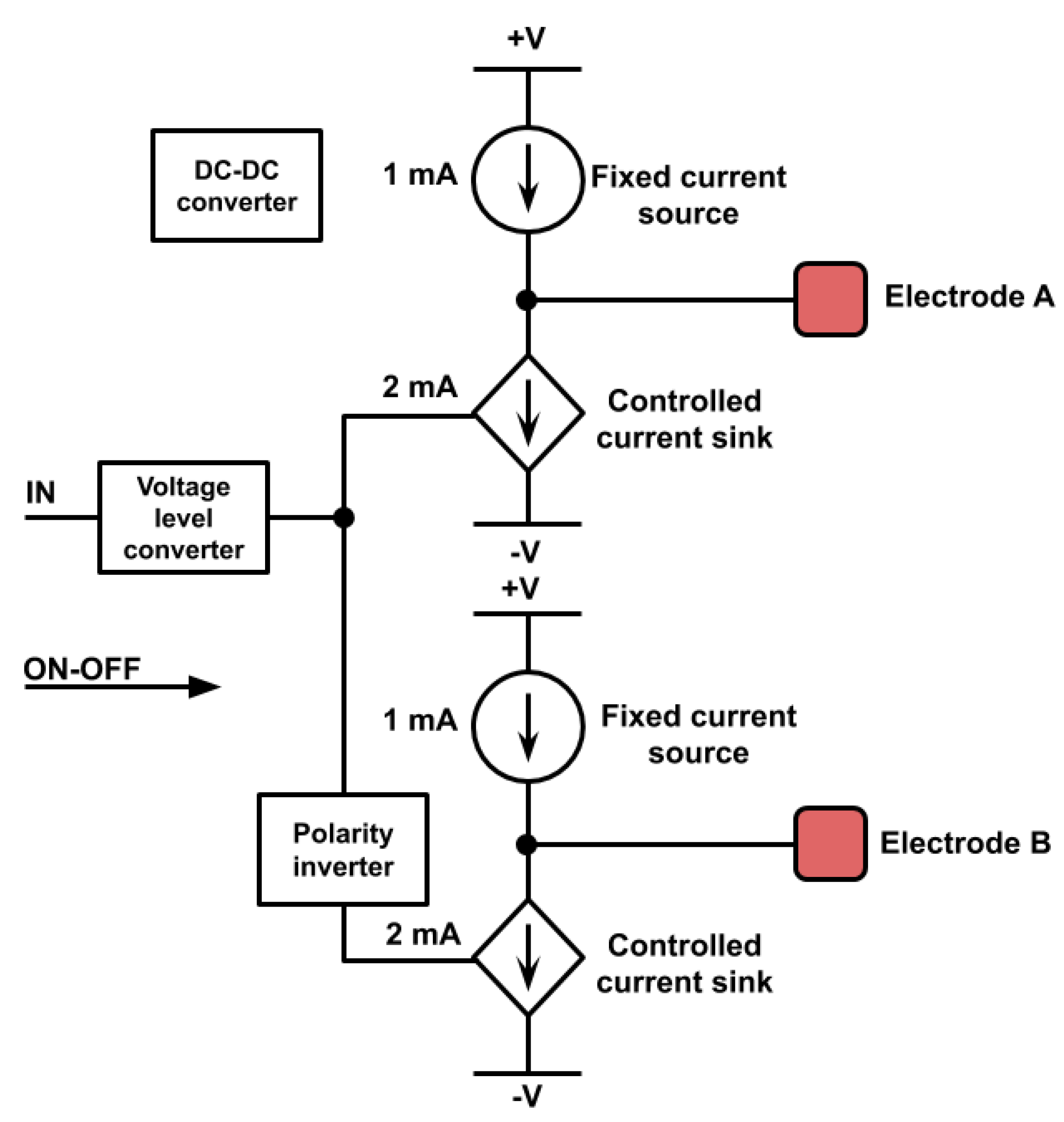
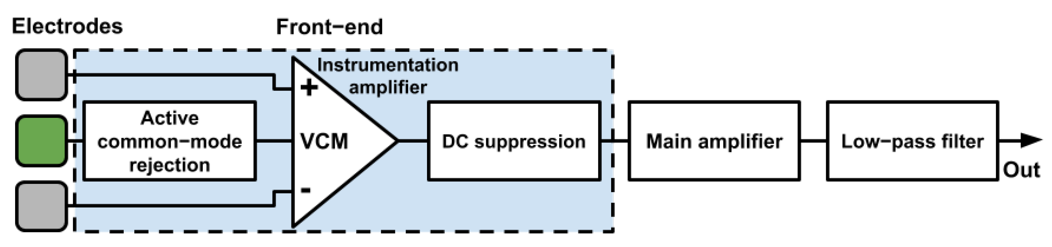
The proposed system comprises two main components: (i) differential current driver and (ii) sensing amplifier. Figure 1 presents the block diagram for the differential current driver component, whereas Figure 2 shows the block diagram for the sensing amplifier component. Figures are detailed next. The first diagram illustrates two electrodes (A and B), inverters, converters, and the current flow. The second diagram also shows the electrodes and all the steps to amplify the signal as the instrumentation amplifier, DC suppression, main amplifier, and low-pass filter. The following subsections detail the preliminaries and the two main components.
3.1. Preliminaries
In general, devices on the body communicate wirelessly through radio frequency (RF) technology. However, they suffer from high attenuation of signals provided by the body tissue [19,20]. We consider that galvanic coupling can provide power efficiency and security for communication beyond a significant reduction in vulnerability to attacks [15,21]. In addition, it enables implementing sensor devices without using RF components and antennas [22]. These advantages make galvanic coupling useful for many applications, mainly in the healthcare field.
Our goal in using signal transmission through an HBC structure is to guarantee confidentiality, integrity, and data availability. Furthermore, the developed galvanic communication platform comprises low-cost, miniaturized hardware that can be linked to vital signs monitoring devices in loco and is non-invasive.
3.2. Differential Current Driver
There are two electrical current types: direct current (DC) and alternating current (AC). Direct current travels in one direction and does not change. Alternating current can switch directions or vary in magnitude, usually at a specific frequency. In galvanic coupling, an alternating current is injected into the skin by the differential current driver (Figure 1). The skin acts as a communication medium and carries the signal throughout the body.
The differential current driver component is responsible for coupling data frames to the communication medium, converting the message bits into current pulses at the electrodes. The proposal is inspired by the circuit proposed by Wegmüller [10], which can be miniaturized as an application specific integrated circuit (ASIC), becoming a relevant candidate to be part of a bio-sensor. Our work focuses on designing a lightweight circuit embedded in wearable devices, with constrained computational resources and energy. This circuit is optimized for high-speed communication and, finally, it supports active interference rejection.
We adopt a baseband signaling scheme to make possible the use of low-cost, general-purpose microcontrollers. Baseband transmissions typically use digital signaling over a single wire (the body). The digital signal in baseband transmission occupies the entire network medium’s bandwidth to transmit a single data signal. Baseband communication is bidirectional, allowing devices to send and receive data through a single cable. However, data transmission and reception cannot occur on the same wire at the same time. The circuit produces the output current pulses according to the input combinations, as shown in Table 2.
Due to the on-off nature of digital devices, our circuit supports several coding schemes such as non-return to zero (NRZ), alternated mark-inversion (AMI), Manchester, and high-density bipolar 3 (HDB3), which represent digital data through variations in amplitude and duration in a carrier wave. We use the NRZ scheme for simplicity and because it consumes less power [15]. As in Figure 1, the differential current driver component presents the following elements: (i) voltage level converter, (ii) polarity inverter, (iii) fixed current sources, (iv) controlled current sinks, and (v) DC-DC converter. We describe each element next.
Voltage level converter: it converts the 0V or 5V input voltage to symmetric output voltage, ±1 V, driving the controlled current sinks when ON-OFF input is active (0V). This circuit translates signals from one logic level or voltage domain to another, allowing compatibility between integrated circuits (ICs) with different voltage requirements.
Polarity inverter: it changes the pulse polarity. As polarities applied to controlled current sinks are opposed, they are never active at the same time. Therefore, the signal output represents the characteristics of the different described baseband modulation schemes.
Fixed current sources: when the ON-OFF input is active (0V), they supply a constant current (1 mA), drained by the controlled current sinks or injected in the connected electrode, depending on the sink state. Thus, a constant current source is a valuable component because it can supply steady current even if there are changes in resistance, and even a wide variance in the resistance. This is essential because the circuit needs a steady current supply, without fluctuations.
Controlled current sinks: they are active when the ON-OFF input is 0V, and the other inputs are positive. In such a case, they drain a fixed current equal to 2 mA. Otherwise, the drained current is zero. By activating the current sink, the connected electrode demands an additional 1 mA current.
DC-DC converter: it is employed to provide a DC-regulated power supply, a constant DC power supply to the designed circuit. As the functional blocks are analog circuits, they need a symmetric power supply at defined levels. The DC-DC converter provides these symmetric voltages from a single 5V power supply.
3.3. Sensing Amplifier
This circuit block recovers the signal injected in the body through the differential current driver. The signal is represented by a voltage that can be identified by the receiving electrodes located a short distance from the source. The receiver device equipped with a sensing amplifier makes it possible to read and decode data using analog measuring devices, such as oscilloscopes, data acquisition boards, or microcontrollers.
Figure 2 shows the design diagram for the sensing amplifier component. This circuit detects the very low differential voltage at the sensing electrodes produced by ionic currents generated at the driver end. The differential voltage is immersed in a relatively strong common-mode interference voltage, which is present due to the proximity to power cords. The sensing amplifier suppresses the DC voltage from the electrode-electrolyte interface. It rejects the common-mode interference and amplifies the differential voltage to a level that can be registered by a measurement instrument, such as an oscilloscope. This circuit is powered by a 9V battery.
The sensing amplifier comprises the front-end, DC suppression, main amplifier, low-pass filter, and active common-mode rejection.
Front-end: it includes an integrated instrumentation amplifier, and it features low noise, low offset, and high input impedance. We limit the gain to 20 V/V, thus avoiding saturation due to the DC voltage produced by the electrode–electrolyte interface.
DC suppression: it is an active high-pass filter for suppressing the DC voltage produced by the electrode–electrolyte interface, amplified by the front-end. The cutoff frequency is 1 Hz to prevent the deformation of square-shaped pulses.
Main amplifier: it is responsible for reaching the high-gain amplification, making the low differential voltages in the electrodes detectable by the other circuit blocks. This amplifier’s gain is 50 V/V; the global gain is 1000 V/V.
Low-pass filter: this stage limits the amplifier bandwidth to prevent aliasing at the sampling stage. The frequency response can be freely modified to satisfy codification/modulation restrictions. For testing purposes, we set for a 10 kHz Chebbyshev response with a 0.5 dB ripple.
Active common-mode rejection: the high impedance featured by the electrode–electrolyte interface allows easy coupling of electrical interference to the conducting medium. The power-line interference usually coupled to the electrolyte medium can be as high as 1 V. Thus, retrieving the 0.5 mV pulses from such a hostile medium is not a simple task, and to reduce the electrical pollution, we include a driven common-mode rejection (or right-leg [23]) circuit in our design, which requires a third electrode.
4. Evaluation Methodology
This section details the experimentation settings, metrics, and results followed and achieved during the proposed system’s evaluation.
4.1. Experimental Setup
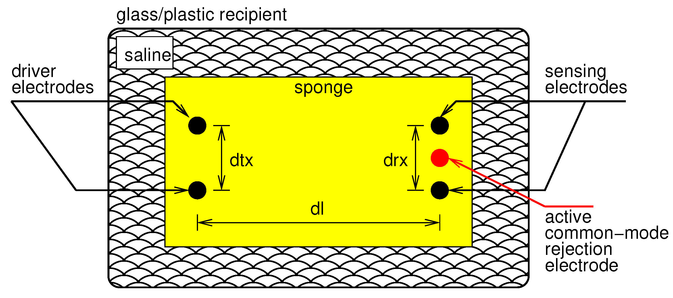
Figure 3 illustrates a model of the environment employed to conduct the experiments for the evaluation of the proposed system. We evaluated our system using (i) the phantom represented in Figure 3, which was composed of a saline solution. The recipient (plastic or glass) contained a saline solution at 0.9%. We placed three types of pin in the sponge (in the figure, pins are represented by the large dark and red dots), with two pins as driver electrodes (left dark dots), two pins as sensing electrodes (right dark dots), and one as an active common-mode rejection electrode (red dot). We directly inserted the clips in the electrodes into a cleaning sponge to improve the mechanical stability of the experimental setup, following the model defined in Figure 3. The sponge, the dimensions, and the containers’ materials of manufacture do not influence the experiment since they do not modify the ionic medium’s properties.
The pair of driver electrodes is aligned, as well as the pair of sensing electrodes and the common-mode rejection electrode. Pins playing the role of driver electrodes are distant from each other by a distance of , whereas the pins playing the role of sensing electrodes are distant from each other by a distance of . The distance between the pair of driver electrodes and the pair of sensing electrodes is . We aligned the common-mode rejection electrode with the sensing electrodes, and it was an equal distance from each of the sensing electrodes. We employed these distances as factors in our experiments, i.e., we varied them to analyze results for the different distances.
We also used a configuration with phantom tissue to accomplish another experiment, whose objective was to determine the bit error rate (BER). BER can be affected by many factors, including signal to noise, distortion, and jitter. To measure BER, we performed 10 repetitions, increased the transmitted data payload, and varied . The data payload consisted of 1000 filtered ECG samples [24], where each sample was 8 bits. We captured the data flow using a low-cost data acquisition board (DAQ-ADALM1000) connected to the amplifier sensor module’s output.
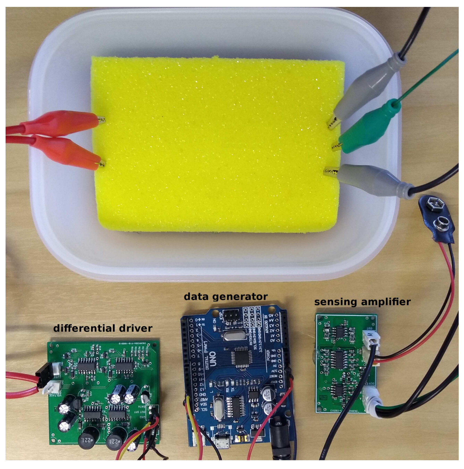
Figure 4 shows a picture of the real environment employed for evaluations. One can see the recipient and the sponge involved with the saline solution and the positioned electrodes. To determine the bit error rate (BER), we used a recipient with 20 cm × 30 cm dimensions. Figure 4 shows the real coupling boards (differential driver and sensing amplifier boards), designed following the specifications in Section 3, and the data generator (workload generator) board.
The workload generator board takes as a basis an Arduino Uno. The workload generator supplies the differential driver board with a small bit sequence. Notably, we fixed the sequence of bits in these experiments to 0101001100001111. In this case, we fixed bit duration to 1 ms, following the NRZ scheme. Positive pulses generate logic level 0, and negative pulses generate logic level 1. We continuously repeated the bit sequence during the tests after an interval of 16 ms for each of the 10 repetitions. We connected the sensing amplifier’s output to a USB oscilloscope (Handyscope HS3, by TiePie engineering, The Netherlands), which had data recording functionality. We set a 50 kHz sample-frequency with 12-bit vertical resolution. We employed this setup to find the maximum communication band rate of our system. We varied the data size and minimal bit duration.
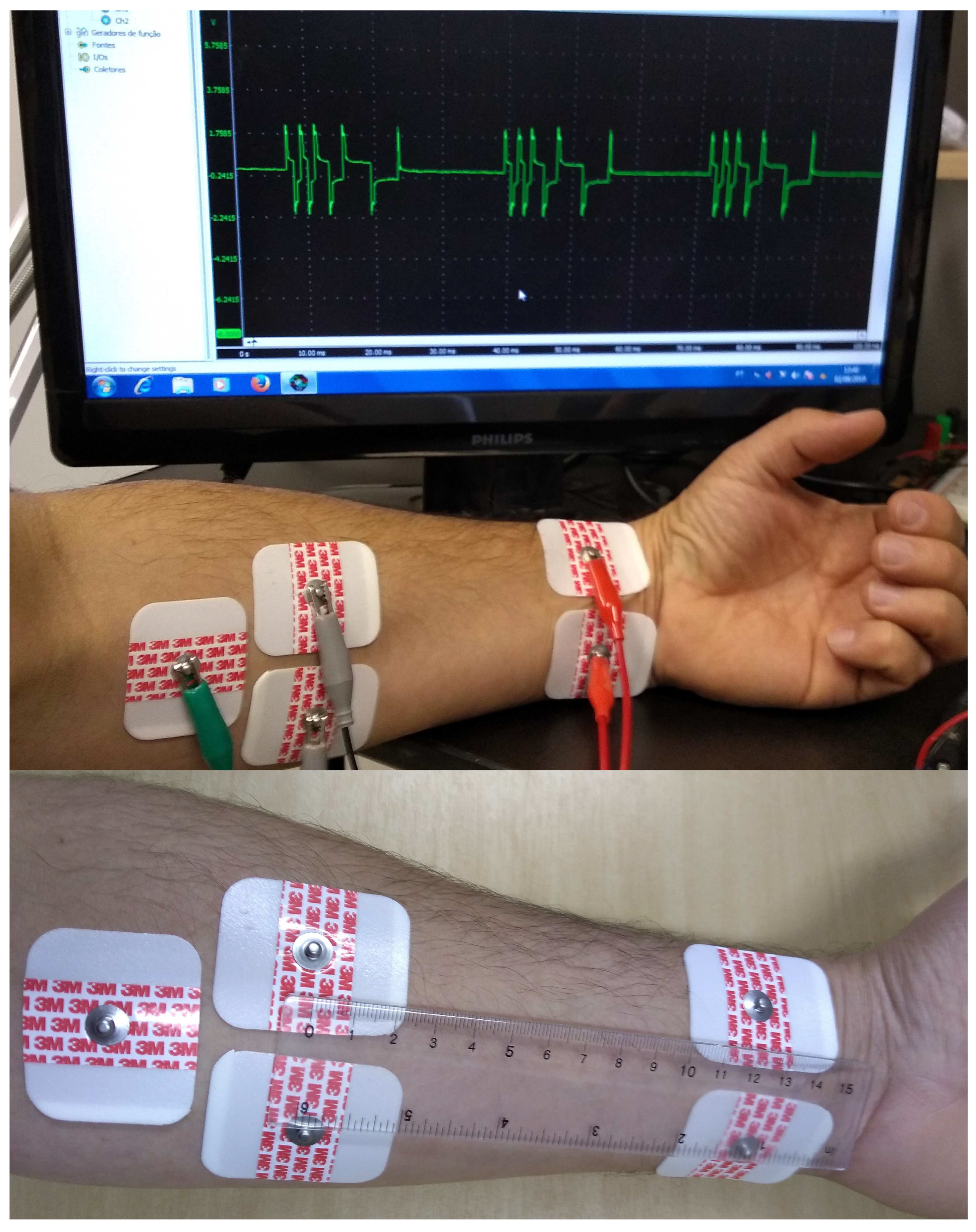
In addition to the phantom-based experiments, we also conducted another set of experiments. We connected the coupling system directly (ii) to the human body through disposable adhesive surface electrodes. The electrodes were positioned on the forearm, as shown in Figure 5. For safety reasons, the coupling boards were powered by a battery during the human-body experiments. In Figure 5, we also highlight a snapshot of the data retrieved by the system, which is directly coupled to the human body. In this case, we set the distance between the differential driver and sensing electrodes to 12 cm.
4.2. Results
We followed the setup shown in Figure 3 to define the distances between electrodes for the best sensing amplifier voltages. Table 3 summarizes the voltages recorded at the sensing amplifier for different distances between pairs of electrodes. We kept the total distance dl constant (10 cm), and we varied the distance between the pair of electrodes. We analyzed these distances and their variations in both scenarios: when in the phantom and on the forearm. Considering the dimensions and characteristics of a real human forearm, the scenario that presented the highest peak-to-peak voltage (3.7 V) was where we separated the sensing and driver electrodes by a 5 cm distance.
We evaluate the forearm scenario, presented in Figure 5, comparing the injected bit sequence and the sequence the system can decode. Figure 6 shows the amplifier circuit output and the decoder output. The amplifier shows the sensing amplified signal without any further processing. The decoder output shows the signal produced by a matched-filter applied to the sensed voltage and the result from a threshold detector. The detected sequence fully matches the generated signal.
When considering the complete galvanic data transmission system presented, it is possible to reach a bit time interval of 90 s, representing an optimal throughput of 11.11 kbps. This data rate supports different applications, such as the use of cryptography keys [25], user authentication [26], vital signs monitoring, and their transmission. In summary, for those reasons, the designed low-cost system is suitable for HBC.
Therefore, we evaluate BER considering the bit time interval of 90 s, and collecting the data flow through the DAQ. The hardware set does not present errors when the electrodes are separated by 10 cm (i.e., dl = 10 cm). When we increase dl to 20 cm, the observed BER is of . According to [20], with this value, the system provides reliable communication. Achieving this rate is also the target in [15]. We consider this a low BER dl since in most cases, practical applications are limited to lower distance ranges. Moreover, in more than 93% of cases, the error occurs in only one bit of each data packet, which can easily be corrected using simple error detection techniques.
Table 4 presents a comparison of the proposed prototype with equivalent works in the literature. According to Table 4, one can note that even operating in a frequency range of up to 10 kHz, the prototype we propose in this work achieves a throughput of ≈ 2.3× higher than Wegmueller et al. [10] with equivalent bit error rate. The throughput is even higher when compared to Gao et al. [14] and, in this case, the new prototype can be as much as ≈ 4.6× better. It is important to note that our proposal presents a null bit error rate for HBC channels with a communication distance of up to 10 cm. On the other hand, Gao et al. [14] present a considerable bit error rate at this same condition. As in Wegmueller et al. [10], the design of the current prototype also limits the peak current to 1 mA, ensuring user safety. However, our approach has superior energy efficiency since it consumes approximately only 50.53 W per bit, and the Wegmueller et al. solution consumes 83.33 W.
However, the proposed circuit has different bottlenecks. The communication is limited by a 10 kHz filter at the sensing amplifier and by the I/O and processing constraints of the Arduino and analog to digital converter (ADC). The low-pass filter cutoff frequency must be increased, and a faster processor and ADC should be employed to raise the data rate of the actual circuit. This goal is a challenge, but is out of this work’s scope since we have focused first on designing a low-cost off-the-shelf HBC system.
4.3. Application Scenarios and Consumption Analysis
This paper presents a low-cost miniaturizable electronic system capable of coupling digital signals to human tissue. Our system has a data transmission rate of up to 11.11 kbps without errors, for distances up to 10 cm. The confinement of signals within the user’s body provides security and confidentiality for the transmitted data [15]. In this way, the system is mainly suitable for use in applications that transmit sensitive data. We emphasize its importance in applications such as user authentication [26,27,28] and cryptographic symmetric key agreement algorithms [3]. Thus, galvanic communication enables carrying out the key agreement in a secure and plug-and-play mode. The minimum key size of 128 bits is well established to provide security for the key algorithms [25]. Therefore, our system is capable of transmitting an encryption key in 0.0115 s.
Furthermore, we can consider using the system developed for the direct transmission of clinical data from patients. Data such as temperature, blood pressure, and electrocardiogram, among others, have a measurement rate lower than that achieved by the system [1,29]. For this purpose, the system is miniaturizable, and could feasibly be applied in implantable sensors. An example is the subcutaneous glucose sensor, which is implanted below the skin (depth of 4 mm) with a less than 10 kbps data rate [30].
Battery capacity determines the operating lifetime of wearable devices. We rely on a 10.8 V rechargeable lithium-ion battery with 2.8 Ah capacity, resulting in 30,240 mWh [31]. We estimate the wearable device consumes an average of 561.47 mW with a standard deviation of ±10.69 mW. In this sense, this battery supports our device for 53.85 h in full-time data transmission.
In applications with intermittent data transmission, such as user authentication (continuous or non-continuous) and cryptographic key agreement, the system considerably extends the battery life. Besides the use of traditional energy sources, several new technologies allow energy harvesting from the human body, for example, thermoelectric generators (TEGs), which convert thermal energy into electrical energy [32,33,34,35]. A TEG can generate 20 W/cm of electrical energy density at a walking speed of about 1.1 m/s [35]. Our system transmits a complete 128-bit cryptographic key with an energy cost of 6.47 mW, which would be equivalent to the power generated by a 10 cm TEG during a 32.28 second walk. We can also consider adding alternative energy sources in implantable versions of the device [36,37]. Thus, it is necessary to use, for example, designed solutions to convert the human-body thermal radiation into energy. In [38], a device capable of generating up to 2.2 W/cm of power loss is shown. Therefore, considering this technology’s addition with an area of 10 cm, our solution would need approximately 2.29 seconds to transmit one bit. Table 5 summarizes information regarding energy production from complementary sources that can be attached to the project. It also estimates the time needed to produce enough energy to transmit each bit and a complete cryptographic key.
5. Conclusions
In this article, we have presented a low-cost electronic system that transfers collected data by a secondary channel: the ionic environment. We designed our electronic system as an experimental setup for studying HBC, thus allowing communication between instruments, sensors, and actuators through human-body tissues. The main contribution of this work is the low-cost and miniaturized galvanic communication platform for HBC with off-the-shelf electronic components, whose schematic, printed circuit board (PCB) layout, and related software are publicly available for the community. We conducted the experimental evaluation using a phantom composed of saline (0.9%) and a real human forearm through adhesive surface electrodes. In both experiments, the new system has shown itself to be fully functional and stable, reaching a data throughput of up to 11 kbps, which allows our prototype to work with the IEEE 802.15.6 standard for WBAN. Moreover, this data rate supports different applications such as the use of cryptography keys, user authentication, and vital signs monitoring and transmission. As future work, we plan to expand the sensing amplifier hardware to achieve the highest possible data throughput with the differential driver. We also intend to expand the sensing amplifier hardware, attaching it to a higher sample rate analog-to-digital converter.
Author Contributions
Conceptualization, A.V.-C., M.M. and J.A.M.N.; Formal analysis, A.V.-C.; Funding acquisition, M.N. and J.A.M.N.; Investigation, K.K.C., M.N. and J.A.M.N.; Methodology, K.K.C. and J.A.M.N.; Project administration, M.N. and J.N.; Resources, M.N. and J.A.M.N.; Software, K.K.C.; Supervision, A.V., A.S. and J.A.M.N.; Validation, K.K.C. and M.N.; Visualization, M.M. and A.S.; Writing–original draft, A.V.-C.; Writing–review and editing, K.K.C., A.V., A.S., M.N. and J.A.M.N. All authors have read and agreed to the published version of the manuscript.
Funding
This study was financed in part by the Coordenação de Aperfeiçoamento de Pessoal de Nível Superior—Brasil (CAPES)—Finance Code 001. The authors also thank Universidade Federal de Viçosa (UFV) and the agencies CNPq (CUIDA project, grant #426701/2018-6, FAPEMIG, and the joint NSF and RNP HealthSense project (grant #99/2017), which also partially supported this study.
Conflicts of Interest
The authors declare no conflict of interest.
References
- Teshome, A.K.; Kibret, B.; Lai, D.T.H. A Review of Implant Communication Technology in WBAN: Progress and Challenges. IEEE Rev. Biomed. Eng. 2019, 12, 88–99. [Google Scholar] [CrossRef]
- Chen, X.M.; Pun, S.H.; Zhao, J.F.; Mak, P.U.; Liang, B.D.; Vai, M.I. Effects of human limb gestures on galvanic coupling intra-body communication for advanced healthcare system. Biomed. Eng. Online 2016. [Google Scholar] [CrossRef] [Green Version]
- Kompara, M.; Hölbl, M. Survey on security in intra-body area network communication. Ad Hoc Netw. 2018, 70, 23–43. [Google Scholar] [CrossRef]
- Movassaghi, S.; Abolhasan, M.; Lipman, J.; Smith, D.; Jamalipour, A. Wireless body area networks: A survey. IEEE Commun. Surv. Tutor. 2014, 16, 1658–1686. [Google Scholar] [CrossRef]
- Asogwa, C.O.; Aryo Bay, J.; Mclaughlin, P.; Collins, S.F.; Lai, D.T. A galvanic intrabody method for assessing fluid flow in unilateral lymphoedema. Electronics 2017, 6, 47. [Google Scholar] [CrossRef] [Green Version]
- Yamamoto, K.; Nishida, Y.; Sasaki, K.; Muramatsu, D.; Koshiji, F. Electromagnetic field analysis of signal transmission path and electrode contact conditions in human body communication. Appl. Sci. 2018, 8, 1539. [Google Scholar] [CrossRef] [Green Version]
- IEEE Standard for Local and Metropolitan Area Networks—Part 15.6: Wireless Body Area Networks; IEEE Std 802.15.6-2012; Institute of Electrical and Electronics Engineers: New York, NY, USA, 2012; pp. 1–271. [CrossRef]
- Tomlinson, W.J.; Banou, S.; Yu, C.; Stojanovic, M.; Chowdhury, K.R. Comprehensive survey of galvanic coupling and alternative intra-body communication technologies. IEEE Commun. Surv. Tutor. 2018, 21, 1145–1164. [Google Scholar] [CrossRef]
- Swaminathan, M.; Cabrera, F.S.; Pujol, J.S.; Muncuk, U.; Schirner, G.; Chowdhury, K.R. Multi-path model and sensitivity analysis for galvanic coupled intra-body communication through layered tissue. IEEE Trans. Biomed. Circuits Syst. 2015, 10, 339–351. [Google Scholar] [CrossRef] [PubMed] [Green Version]
- Wegmueller, M.S.; Huclova, S.; Froehlich, J.; Oberle, M.; Felber, N.; Kuster, N.; Fichtner, W. Galvanic coupling enabling wireless implant communications. IEEE Trans. Instrum. Meas. 2009, 58, 2618–2625. [Google Scholar] [CrossRef]
- Seyedi, M.H.; Lai, D. A Novel Intrabody Communication Transceiver for Biomedical Applications; Springer: New York, NY, USA, 2017. [Google Scholar]
- Li, J.W.; Chen, X.M.; Pun, S.H.; Mak, P.U.; Gao, Y.M.; Vai, M.I.; Du, M. Bit error rate estimation for galvanic-type intra-body communication using experimental eye-diagram and jitter characteristics. In Proceedings of the 2013 35th Annual International Conference of the IEEE Engineering in Medicine and Biology Society (EMBC), Osaka, Japan, 3–7 July 2013. [Google Scholar] [CrossRef]
- Vasić, Ž.L.; Krois, I.; Cifrek, M. Effect of transformer symmetry on intrabody communication channel measurements using grounded instruments. Automatika 2016, 57, 15–26. [Google Scholar] [CrossRef] [Green Version]
- Gao, Y.M.; Ye, Y.T.; Vai, M.I.; Du, M.; Pun, S.H. Channel modeling and power consumption analysis for galvanic coupling intra-body communication. EURASIP J. Wirel. Commun. Netw. 2016, 2016, 106. [Google Scholar] [CrossRef] [Green Version]
- Tomlinson, W.J.; Banou, S.; Yu, C.; Nogueira, M.; Chowdhury, K.R. Secure On-skin Biometric Signal Transmission using Galvanic Coupling. In Proceedings of the IEEE Conference on Computer Communications (INFOCOM), Paris, France, 29 April–2 May 2019; pp. 1135–1143. [Google Scholar]
- Sabban, A. Active Compact Wearable Body Area Networks for Wireless Communication, Medical and IoT Applications. Appl. Syst. Innov. 2018, 1, 46. [Google Scholar] [CrossRef] [Green Version]
- Park, M.J.; Kang, T.; Lim, I.G.; Oh, K.I.; Kim, S.E.; Lee, J.J.; Park, H.I. Low-Power, high data-rate digital capsule endoscopy using human body communication. Appl. Sci. 2018, 8, 1414. [Google Scholar] [CrossRef] [Green Version]
- Wegmueller, M.S.; Kuhn, A.; Froehlich, J.; Oberle, M.; Felber, N.; Kuster, N.; Fichtner, W. An attempt to model the human body as a communication channel. IEEE Trans. Biomed. Eng. 2007, 54, 1851–1857. [Google Scholar] [CrossRef]
- Swaminathan, M.; Muncuk, U.; Chowdhury, K.R. Tissue safety analysis and duty cycle planning for galvanic coupled intra-body communication. In Proceedings of the 2016 IEEE International Conference on Communications (ICC), Kuala Lumpur, Malaysia, 22–27 May 2016; pp. 1–6. [Google Scholar]
- Swaminathan, M. Wireless Intra-Body Communication for Implantable and Wearable Body Devices Using Galvanic Coupling. Ph.D. Thesis, Northeastern University, Boston, MA, USA, 2017. [Google Scholar]
- Ibrahim, I.; Razak, A.; Ahmad, A.; Salleh, M.; Khir, R. Body Mass Index (BMI) Effect on Galvanic Coupling Intra-Body Communication. J. Telecommun., Electron. Comput. Eng. (JTEC) 2018, 10, 177–180. [Google Scholar]
- Ali, A.; Inoue, K.; Shalaby, A.; Sayed, M.S.; Ahmed, S.M. Efficient Autoencoder-Based Human Body Communication Transceiver for WBAN. IEEE Access 2019, 7, 117196–117205. [Google Scholar] [CrossRef]
- Winter, B.B.; Webster, J.G. Driven-right-leg circuit design. IEEE Trans. Biomed. Eng. 1983, BME-30, 62–66. [Google Scholar] [CrossRef] [PubMed]
- Johnson, A.E.; Pollard, T.J.; Shen, L.; Li-wei, H.L.; Feng, M.; Ghassemi, M.; Moody, B.; Szolovits, P.; Celi, L.A.; Mark, R.G. MIMIC-III, a freely accessible critical care database. Sci. Data 2016, 3, 160035. [Google Scholar] [CrossRef] [Green Version]
- Coelho, K.; Damião, D.; Nacif, J.; Borges, A.; Nogueira, M.; Noubir, G. Cryptography Algorithms in Wearable Communication: An Empirical Analysis. IEEE Commun. Lett. 2019, 23, 1931–1934. [Google Scholar] [CrossRef]
- Nakayama, F.; Lenz, P.; Banou, S.; Nogueira, M.; Santos, A.; Chowdhury, K.R. A Continuous User Authentication System Based on Galvanic Coupling Communication for s-Health. Wirel. Commun. Mob. Comput. 2019, 2019, 9361017. [Google Scholar] [CrossRef]
- Nakayama, F.; Cremonezi, B.; dos Santos, A.L.; Nogueira, M.; Chowdhoury, K.; Banou, S.; Cerqueira, E.C. Autenticação Contínua e Segura Baseada em Sinais PPG e Comunicação Galvânica. In Anais do XXXVII Simpósio Brasileiro de Redes de Computadores e Sistemas Distribuídos; SBC: Porto Alegre, Brazil, 2019; pp. 707–720. [Google Scholar]
- Maity, S.; Das, D.; Jiang, X.; Sen, S. Secure human-internet using dynamic human body communication. In Proceedings of the 2017 IEEE/ACM International Symposium on Low Power Electronics and Design (ISLPED), Taipei, Taiwan, 24–26 July 2017; pp. 1–6. [Google Scholar]
- Tewari, A.; Verma, P. Security and privacy in e-healthcare monitoring with WBAN: A critical review. Int. J. Comput. Appl. 2016, 136, 37–42. [Google Scholar] [CrossRef]
- Pandey, S.; Tiwari, P.K.; Byun, T.Y. Integration of bio-sensing with information and communication to provide improved health-care services. In Embedded and Multimedia Computing Technology and Service; Springer: New York, NY, USA, 2012; pp. 509–516. [Google Scholar]
- Technology Parkway. Rechargeable 3S1P Battery with Connector. 2020. Available online: https://www.ultralifecorporation.com/ECommerce/product/ubbl21/li-ion-rechargeable-3s1p-battery (accessed on 15 October 2020).
- Proto, A.; Bibbo, D.; Cerny, M.; Vala, D.; Kasik, V.; Peter, L.; Conforto, S.; Schmid, M.; Penhaker, M. Thermal energy harvesting on the bodily surfaces of arms and legs through a wearable thermo-electric generator. Sensors 2018, 18, 1927. [Google Scholar] [CrossRef] [PubMed] [Green Version]
- Jaziri, N.; Boughamoura, A.; Müller, J.; Mezghani, B.; Tounsi, F.; Ismail, M. A comprehensive review of Thermoelectric Generators: Technologies and common applications. Energy Rep. 2019. [Google Scholar] [CrossRef]
- Huu, T.N.; Van, T.N.; Takahito, O. Flexible thermoelectric power generator with Y-type structure using electrochemical deposition process. Appl. Energy 2018, 210, 467–476. [Google Scholar]
- Hyland, M.; Hunter, H.; Liu, J.; Veety, E.; Vashaee, D. Wearable thermoelectric generators for human body heat harvesting. Appl. Energy 2016, 182, 518–524. [Google Scholar] [CrossRef] [Green Version]
- Ghomian, T.; Mehraeen, S. Survey of energy scavenging for wearable and implantable devices. Energy 2019, 178, 33–49. [Google Scholar] [CrossRef]
- Tholl, M.; Akarçay, H.; Tanner, H.; Niederhauser, T.; Zurbuchen, A.; Frenz, M.; Haeberlin, A. Subdermal solar energy harvesting—A new way to power autonomous electric implants. Appl. Energy 2020, 269, 114948. [Google Scholar] [CrossRef]
- Ghomian, T.; Kizilkaya, O.; Choi, J.W. Lead sulfide colloidal quantum dot photovoltaic cell for energy harvesting from human body thermal radiation. Appl. Energy 2018, 230, 761–768. [Google Scholar] [CrossRef]
Figure 1.
Differential current driver block. Data bits written at the inputs (IN and ON-OFF) converted into current pulses at the electrodes A and B.
Figure 1.
Differential current driver block. Data bits written at the inputs (IN and ON-OFF) converted into current pulses at the electrodes A and B.

Figure 2.
Sensing amplifier block diagram. Electrodes collect the differential voltage together with noise and interference and a third is linked to the active common-mode rejection circuit.
Figure 2.
Sensing amplifier block diagram. Electrodes collect the differential voltage together with noise and interference and a third is linked to the active common-mode rejection circuit.

Figure 3.
Phantom diagram showing electrode positions and distances.

Figure 4.
Full experimental setup: boards, workload generator, and phantom.

Figure 5.
Battery-powered coupling system connected to the forearm using disposable electrodes.

Figure 6.
Data recorded by the system connected to the human forearm. Distance between driver and sensing electrodes was 12 cm.
Figure 6.
Data recorded by the system connected to the human forearm. Distance between driver and sensing electrodes was 12 cm.


Table 1.
Galvanic-based human-body communication (HBC)-related work.
| Paper | Hardware | Modulation | Demodulation | Throughput (kbps) | Range (cm) |
|---|---|---|---|---|---|
| [10] | Electronic | DBPSK | Online | 4.8 | 45 |
| [14] | Transformer | FSK | Signal Analyzer | 2.4 | 10 |
| [15] | Transformer | OOK | Matlab | - | 10 |
| [9] | Transformer | - | Oscilloscope | - | 10 |
| [11] | Transformer | - | VNA | - | 20 |
| [12] | Transformer | QPSK | Signal Analyzer | - | 6 |
| [13] | Transformer | - | VNA | - | 16 |
Table 2.
Differential current driver IN/OUT reference values.
| Input Voltage (IN) | ON-OFF | Output Current |
|---|---|---|
| - | 5 V | 0 mA |
| 0 V | 0 V | mA |
| 5 V | 0 V | mA |
Table 3.
Sensing amplifier pulse voltages.
| dtx (cm) | drx (cm) | Pulse Voltage (V) |
|---|---|---|
| 5 | 5 | ±3.7 |
| 5 | 2 | ±2.4 |
| 2 | 5 | ±1.3 |
| 2 | 2 | ±0.6 |
Table 4.
Main results compared to the most significant related works.
| Method | Hardware | Modulation | Bit Rate (kbps) | Frequency Range (kHz) | BER | Channel Length (cm) | Peak Current (mA) | Consumption (mW) |
|---|---|---|---|---|---|---|---|---|
| Proposed | Eletronic | OOK | 11.11 | 10 | 20 | 1 | 561.47 | |
| [10] | Eletronic | DBPSK | 4.8 | 100–250 | 35 | 1 | 400 | |
| [14] | Transformer | FSK | 2.4 | 20–40 | 10 | - | - |
Table 5.
Energy sources and time required for energy production.
| Source | Power (W/cm) | Area (cm) | Energy Production Time to Transmit One Bit (s) | Energy Production Time to Transmit a Cryptographic Key (s) |
|---|---|---|---|---|
| Thermoelectric | 20 | 10 | 0.25 | 32.28 |
| Thermal radiation (IR) | 2.2 | 10 | 2.29 | 293.49 |
Publisher’s Note: MDPI stays neutral with regard to jurisdictional claims in published maps and institutional affiliations. |
© 2020 by the authors. Licensee MDPI, Basel, Switzerland. This article is an open access article distributed under the terms and conditions of the Creative Commons Attribution (CC BY) license (http://creativecommons.org/licenses/by/4.0/).
Share and Cite
MDPI and ACS Style
Vale-Cardoso, A.; Moreira, M.; Coelho, K.K.; Vieira, A.; Santos, A.; Nogueira, M.; Nacif, J.A.M. A Low-Cost Electronic System for Human-Body Communication. Electronics 2020, 9, 1928. https://doi.org/10.3390/electronics9111928
AMA Style
Vale-Cardoso A, Moreira M, Coelho KK, Vieira A, Santos A, Nogueira M, Nacif JAM. A Low-Cost Electronic System for Human-Body Communication. Electronics. 2020; 9(11):1928. https://doi.org/10.3390/electronics9111928
Chicago/Turabian StyleVale-Cardoso, Adriano, Mariana Moreira, Kristtopher Kayo Coelho, Alex Vieira, Aldri Santos, Michele Nogueira, and José Augusto M. Nacif. 2020. "A Low-Cost Electronic System for Human-Body Communication" Electronics 9, no. 11: 1928. https://doi.org/10.3390/electronics9111928
Note that from the first issue of 2016, this journal uses article numbers instead of page numbers. See further details here.