A Low Cost and Fast Cell-to-Cell Balancing Circuit for Lithium-Ion Battery Strings


Department of Electrical Engineering, Soongsil University, Seoul 06978, Korea
*
Author to whom correspondence should be addressed.
Electronics 2020, 9(2), 248; https://doi.org/10.3390/electronics9020248
Submission received: 3 January 2020
/
Revised: 28 January 2020
/
Accepted: 29 January 2020
/
Published: 3 February 2020
(This article belongs to the Special Issue High Power Electric Traction Systems)
Abstract
:This paper proposes a fast cell-to-cell balancing circuit for lithium-ion battery strings. The proposed method uses only one push-pull converter to transfer energy between high- and low-voltage cells directly for a fast balancing speed. The switch network for selecting a certain pair of cells is implemented using relays to achieve a low cost. The control circuit is composed of a battery-monitoring IC and a digital signal processor (DSP) to monitor the cell voltage and to protect the batteries. In order to prove the validity of the proposed method, a prototype circuit is built with twelve lithium-ion batteries in a string. The experimental results show that it takes only 50 min to balance twelve lithium-ion batteries during the charge with 89.5% maximum efficiency. The outstanding performance of the proposed cell balancing circuit is verified through its comparison with other methods in terms of several factors, such as the balancing time and the implementation cost.
1. Introduction
Nowadays, lithium-ion batteries are being used increasingly for automotive applications. A battery string with a large number of cells connected in series and in parallel is necessary for many applications that require high power and high voltage, such as electric vehicles (EVs), hybrid electric vehicles (HEVs), and energy storage systems (ESSs) [1]. For example, the battery in the Tesla Roadster contains 6831 Li-ion cells arranged in 69 strings, with each string including 99 cells [2]. However, all the cells in a string may not have the same characteristics due to subtle differences in the manufacturing process and working conditions. The difference in the characteristics of the cells results in a difference in the cell voltages, and it tends to grow as the charge and discharge cycle repeats. As battery cells in a string are connected in series, the performance of the string is limited to the performance of the weakest cell and, hence, the capacity of the battery string will be reduced. During normal operation, the weakest cell undergoes overdischarge and undercharge and eventually reaches failure. In the meanwhile, the normal cell may experience overcharge because the charge operation continues until the string voltage reaches the nominal value. In this case the voltage of the normal cell may exceed the maximum charge voltage and it may cause an early failure due to the accelerated degradation [1]. Therefore, the cell balancing circuit is crucial for the battery strings or modules [3].
So far, many kinds of cell balancing topologies have been proposed and developed [4,5,6,7,8,9,10,11,12,13,14,15,16,17,18,19,20,21,22,23,24,25,26]. They can be classified as active methods and passive methods [4]. The passive methods that use resistors to discharge the overcharged cells are useful for lead-acid batteries and NiMH batteries. However, they are disadvantageous in that the temperature of the system rises because the power is dissipated by the heat.
Active cell balancing methods can be categorized into four different kinds according to the charge-transfer method such as pack-to-cell method, cell-to-pack method, cell-to-cell method, and cell-to-pack-to-cell method. A comparison of the balancing methods in terms of component count and characteristics is shown in Table 1. It is clear that most of the balancing methods require lots of photo-couplers or pulse transformers to drive the switches and the balancing speed is low.
The cell-to-pack method can be implemented by using a transformer [5] or multiple transformers [6]. As the method requires a lot of MOSFETs and gate drivers, it is high in cost and low in balancing speed. The pack-to-cell method can be implemented by using a multi-output transformer [7] or multiple transformers [8] with a lower number of switches compared to the cell-to-pack method, but it requires a higher number of transformers. Hence, it is complex in design and high in cost. Although the cell-to-pack-to-cell method [9], which is a combination of two methods, exhibits a faster balancing speed, it is not preferred. As it needs a lot of photo-couplers to drive the bidirectional switches and two DC–DC converters, it is complex and expensive to implement.
The cell-to-cell methods can be a preferable option in terms of cost, complexity, and balancing speed. There are several topologies developed based on the cell-to-cell balancing method [10,11,12]. They include two kinds of method―the adjacent cell-to-cell method and the direct cell-to-cell method. The adjacent cell-to-cell method transfers the charge between two adjacent cells through the capacitors [10,11,12,13,14], the inductors [15,16,17], or a combination of the two [18] as a resonant tank. As the bidirectional switches are driven using pulse transformers or photo-couplers, the method is high in cost and complex in implementation. The direct cell-to-cell method is developed to transfer the charge directly from any cell to any cell to get high efficiency. In this method, because the single switched capacitor [19] or single switched inductor [20,21] is used as a media for the charge transfer, the method is easier to implement but has a longer balancing time. The cell-to-cell LC resonant topology in [22] can achieve higher efficiency due to the soft-switching operation but the balancing speed is not fast enough and a large number of switches and gate drivers are required to implement the bidirectional switches. The coupled inductor topology in [23] and the multi-winding transformer topology in [24] use only one core and one transformer for the charge transfer, respectively. Although both methods are advantageous in terms of cost, they are complex to implement.
A direct cell-to-cell method using a DC–DC converter is proposed and discussed in [25,26]. A low-cost balancing circuit is proposed by using relays in [25]. The proposed circuit in [26] achieves better performance but has a higher cost. Based on the previous study, in this research a new cell-to-cell balancing circuit for lithium-ion battery strings is proposed to overcome the drawbacks of the conventional cell balancing methods. In the proposed topology, the charge is transferred from a high-voltage cell to a low-voltage cell directly by using a push-pull converter. The control of the proposed method is simple and easy to implement. As the relays, which can be driven by the transistor array, are used as cell selection switches, the cost of the balancing circuit can be significantly reduced. The balancing speed can be increased by suitably designing the voltage gain of the push-pull converter such that the balancing current is not decreased much when the voltage difference between two cells becomes smaller. This paper is composed of four sections. In Section 2, all of the details about the proposed method and operating principle are presented. In Section 3, experimental results to show the superiority of the proposed method are presented. In the Section 4, the conclusion is given.
2. Proposed Cell Balancing Circuit
2.1. Structure of the Proposed Cell-to-Cell Balancing Circuit
Figure 1 shows the proposed cell-to-cell balancing circuit composed of three main blocks. The first one is the switch network for connecting a battery cell to each terminal of the converter for the charge transfer. The second one is the push-pull converter for transferring the charge from a high-voltage cell to a low-voltage cell. The third one is the control circuit composed of a monitoring IC for updating the cell voltage and a digital signal processor (DSP) to control the converter and the switch-network operation.
The switch network has two strings of relays. One string of relays, Ra_1 to Ra_n, are used to connect the battery cell to the primary side of the converter via the DC bus, DCa_1 and DCa_2, while the other string of relays, Ra_1 to Ra_n, are used to connect the battery cell to the secondary side of the converter via the DC bus, DCb_1 and DCb_2. It is possible to transfer the charge from any one cell to any other cell in a string.
Unlike the other topologies in [4,5,6,7,8,9,10,11,12,13,14,15,16,17,18,19,20,21,22,23,24,25], which use lots of photo-couplers or pulse transformers to drive the switch, the proposed topology does not require any expensive gate driver circuits. As only a cheap transistor array IC is required to drive the relays on each DC bus, the cost of the system can be significantly reduced. In addition, the IC can share the power supply with the controller, thereby reducing the system cost further.
The isolated push-pull converter is selected for the charge transfer due to its simple structure, easiness of the control, and good efficiency [27]. If the components of the converter are ideal, the turns ratio of the transformer, Np/Ns, can be selected as 1:1 because the voltage deviation among the cells in a string is typically considered less than 0.2V. However, the converter needs to be designed to step up the voltage by considering the voltage drops across the components. In this research, the transformer turns ratio is selected as 1:1.2. As the ripple voltage and current are strictly limited for the lithium-ion batteries during the charge/discharge, the duty cycle of the converter is 0.5 to get a small input/output ripple.
The voltage monitoring IC measures the cell voltages of the string and transmits them to the DSP through I2C (Inter-Integrated Circuit) serial communication. The balancing current is measured by a current sense resistor in the primary side. The current at the secondary side can be calculated with the turn ratio and the efficiency of the converter.
2.2. Considering Transient Voltage Due to The Balancing Current
The internal impedance affects the balancing current and the terminal voltage of the battery. Therefore, it should be considered during the design process of the system. Several battery models have been proposed by several different studies, as shown in [28,29,30,31,32]. A Thevenin equivalent circuit model of the Li-ion battery is widely used to represent the battery impedance, as shown in Figure 2. It is composed of the open circuit voltage (OCV), the polarization resistance, Rp, and ohmic resistance, Ro, and the equivalent capacitance, Cp.
The Vcell and Icell are the terminal voltage and the current of the battery, respectively:
As shown in Equation (1), the current of the battery, Icell, includes two parts. One is the load current of the battery pack, IL, and the other is the balancing current, I(balance_in/balance_out). The load current of the battery pack is a negative value when the battery pack is discharging or a positive value when the battery pack is charging. The balancing current just flows through two cells when the balancing operation is being performed. At the input of the converter, the balancing current, Ibalance_in, flows to discharge the high-voltage cell and it is measured by the resister, Rsense. At the output of the converter, the balancing current, Ibalance_out, flows to charge the low-voltage cell, and it is calculated by Equation (2).
Figure 3 shows the current and voltage of the battery during the pulse charge test. A charge current pulse equal to 5% of the battery capacity is applied and the battery rests for three hours to get the OCV. The test is repeated until the battery is fully charged. The voltage transient during the balancing operation is attributed to the internal resistance of the battery. The direct current internal resistance, RDCIR [31], is defined by the sum of two resistances and can be represented by Equation (3).
As shown in Figure 4, the transient voltage, ΔVt, can be calculated from the voltage difference caused by the current pulse and the value of RDCIR can be calculated by Equation (4).
Therefore, the transient voltage caused by the balancing current during the balancing process can be calculated by Equation (5).
During the balancing process, the transient voltages of two balancing cells are calculated by Equation (5) to estimate the OCV voltage so that all the cells are balanced at the same voltage.
2.3. Operation Principle of the Proposed Balancing Method
Figure 5 shows the balancing algorithm of the proposed method. Firstly, the controller reads the voltages of all cells. If all of them are in the allowable range of the voltage, the controller finds the cell with the lowest voltage, VBmin, and the cell with the highest voltage, VBmax. Then, at the input side, the relay, Ra_max, is closed to connect the cell with VBmax to the input of the converter. Similarly, the relay, Rb_min, is closed to connect the cell with VBmin to the output of the converter. Then, the balancing operation between these two cells starts immediately.
When the selected cells have been balanced, the controller continuously updates all the voltages and the balancing current, and the average voltage of all the cells is calculated again. When one of these two cells reach the average value of the voltage, both relays, Ra_max and Rb_min, are turned off. After that, the next two cells that have the highest and lowest voltage are found and balanced. The balancing process continues until all the cell voltages are balanced.
In Figure 6, the structure of the proposed cell balancing circuit is shown when a certain pair of cells is connected to the converter for the balancing operation. In this case, cell number Bn-1 represents the cell with the highest voltage, and cell number B1 represents the cell with the lowest voltage. Therefore, cell B1 is connected to the output of the converter by turning on relay Rb_1 and cell Bn-1 is connected to the input of the converter by turning on relay Ra_n-1, respectively. All other relays remain turned off. Then these two cells start to become balanced immediately by the operation of the push-pull converter.
3. Experimental Setup and Results
A prototype circuit was implemented for twelve lithium-ion batteries to prove the validity of the proposed balancing method, as shown in Figure 7. A TI DSP TMS320F28335 was used for the control and a TI Bq76940, which can measure from 9 to 15 cells, was used to monitor the voltages of the twelve battery cells. The transistor array and the relays were implemented on the PCB to connect a pair of cells to the push-pull converter. The component list of the proposed system is shown in Table 2. The experimental setup for testing the balancing operation with twelve lithium-ion batteries in a string is shown in Figure 8.
3.1. Experimental Results of the Push–Pull Converter
The converter was designed to work at 100 kHz. The MOSFET’s Qa and Qb operated at a 50% duty cycle to transfer the charge from one cell with a higher voltage to another cell with a lower voltage. Figure 9 shows the waveforms of the push-pull converter when the input cell voltage was 3.8 V and the output cell voltage was 3.65 V, respectively.
The measured efficiency of the push-pull converter was in the range of 85.3% to 89.5%. As the proposed circuit transferred the energy directly between two cells, higher efficiency was achieved.
3.2. Experimental Results of the Cell Balancing Operation of the Proposed Circuit
The balancing circuit needs to work in three modes, such as relaxation mode, charging mode, and discharging mode for fast and high efficiency balancing.
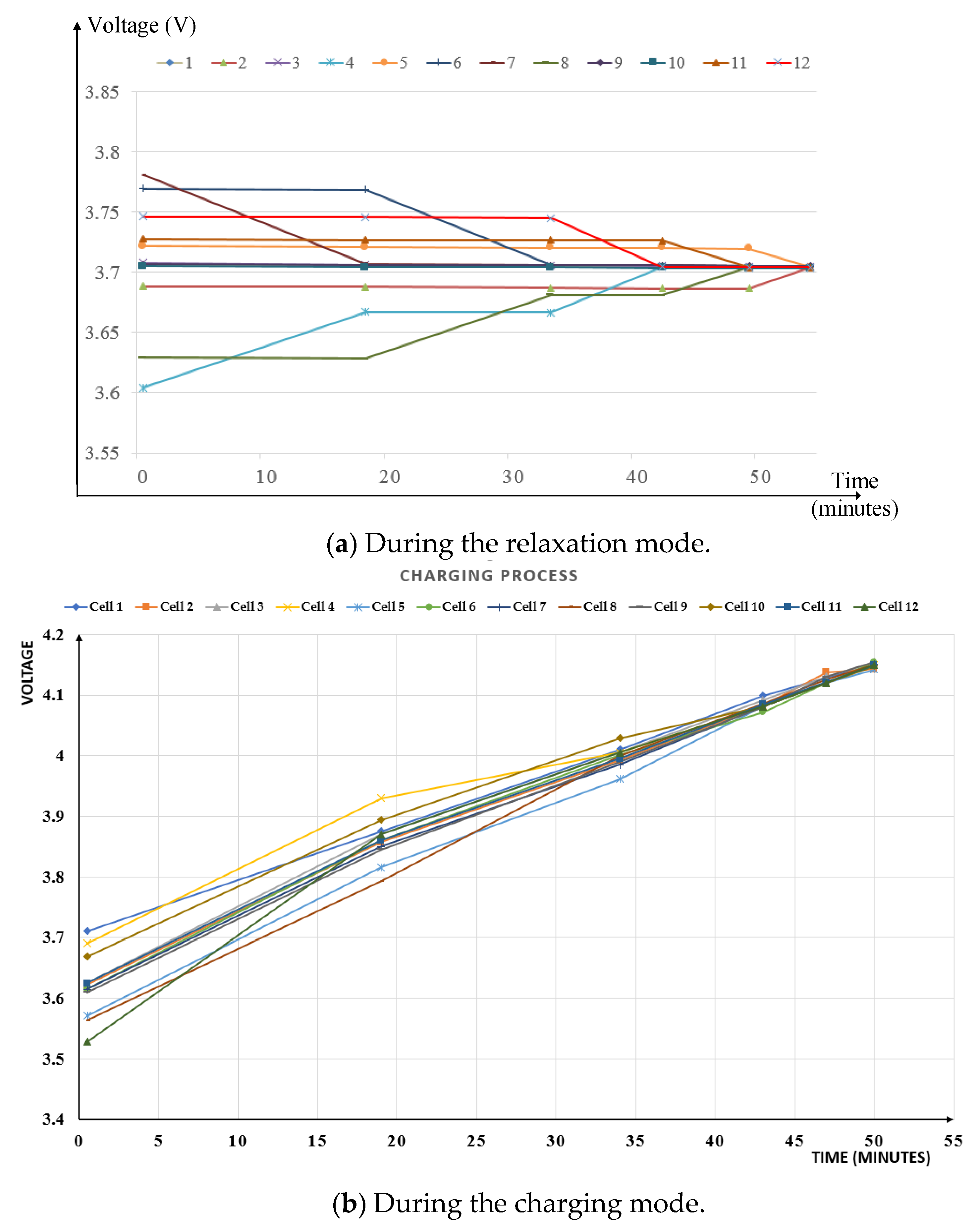
Figure 10a shows the experimental result of the prototype circuit for the twelve cells in a battery string during the relaxation mode. At the start, after reading all of the cell voltages, the cell balancing circuit found that cell number 7 had the highest voltage at 3.78 V and cell number 4 had the lowest voltage at 3.6 V. Hence, these 2 cells were balanced first. After 19 min, cell number 7 reached the average voltage at 3.705 V. Then, the cell balancing system started to find another pair of cells with the highest voltage and lowest voltage. The controller found that cell number 6 and cell number 8 were the new highest-voltage cell and the new lowest-voltage cell, respectively. Then, these two cells were selected and balanced. The balancing process continued until all the cells in the string had the same voltage of 3.705 V with a small difference in voltage (12 mV) after 54 min.
The proposed cell-to-cell balancing method was also tested during the charging and discharging mode as shown in Figure 10b,c, respectively. As shown in Figure 10b, all of the cells were balanced at 4.15 V after 50 min during the charging mode. During the discharging mode all of the cells were balanced at the cut-off voltage of 3.05 V after 55 min, as shown in Figure 10c.
3.3. Comparison between the Proposed and Conventional Cell Balancing Methods
By transferring the charge in a cell with a higher voltage to a cell with a lower voltage directly, a charge balance in between the two cells can be achieved at the same time using the proposed cell balancing method. This can be considered as an advantage of the cell-to-cell balancing method compared to the cell-to-pack-to-cell balancing method, in which one cell is balanced at a time [9].
Table 3 shows a comparison between the proposed method and the other conventional active cell balancing methods concerning the cost, balancing speed, efficiency, complexity in control, and complexity in implementation. The proposed method has several advantages, such as lower component counts, simpler control, faster balancing speed, and higher efficiency.
4. Conclusions
In this paper, a low-cost and fast cell-to-cell balancing circuit and its control method are proposed. The cell balancing operation can be achieved by a simple control strategy and the charges can be transferred directly from one cell to another cell in a battery string by a push-pull converter. A prototype circuit was implemented for twelve lithium-ion batteries in a string and the cell balancing operation was demonstrated. The experimental results show that it takes only 50 min to achieve the cell balancing of twelve cells in a battery string during the charge operation, thereby proving the outstanding performance of the proposed method in terms of balancing time. It also exhibits fair efficiency with a maximum of 89.5% because the energy in a battery cell is transferred directly from a high-voltage cell to a low-voltage cell. The proposed cell balancing can be applied to battery management systems for electric vehicles or energy storage systems.
Author Contributions
V.-L.P. proposed the idea of the paper. The formal analysis and prototype were designed by V.-L.P.; The paper was written by V.-L.P., and reviewed by V.-L.P. and V.-T.D. All the authors were involved in giving the final shape to this manuscript. Moreover, this work was supervised by W.C. All authors have read and agreed to the published version of the manuscript.
Funding
This research was supported by the R&D program for new energy industry through Chungnam Center for Creative Economy and Innovation (CCCEI) funded by Local Government of Chungchengnamdo.
Conflicts of Interest
The authors declare no conflict of interest.
References
- Affanni, A.; Bellini, A.; Franceschini, G.; Guglielmi, P.; Tassoni, C. Battery Choice and Management for New-Generation Electric Vehicles. IEEE Trans. Power Electron. 2005, 52, 1343–1349. [Google Scholar] [CrossRef] [Green Version]
- Available online: https://en.wikipedia.org/wiki/Tesla_Roadster#Battery_system (accessed on 19 December 2007).
- Lukic, S.M.; Cao, J.; Bansal, R.C.; Rodriguez, F.; Emadi, A. Energy Storage Systems for Automotive Applications. IEEE Trans. Ind. Electron. 2008, 55, 2258–2267. [Google Scholar] [CrossRef]
- Daowd, M.; Omar, N.; Van Den Bossche, P.; Van Mierlo, J. Passive and Active Battery Balancing Comparison Based on Matlab Simulation. In Proceedings of the 2011 IEEE Vehicle Power and Propulsion Conference, Chicago, IL, USA, 6–9 September 2011; pp. 1–7. [Google Scholar]
- Imtiaz, A.M.; Khan, F.H. Time Shared Flyback Converter Based Regenerative Cell Balancing Technique for Series Connected Li-Ion Battery Strings. IEEE Trans. Power Electron. 2013, 28, 5960–5975. [Google Scholar] [CrossRef]
- Park, H.S.; Kim, C.E.; Moon, G.W.; Lee, J.H.; Oh, J.K. Two-Stage Cell Balancing Scheme for Hybrid Electric Vehicle Lithium-Ion Battery Strings. In Proceedings of the 2007 IEEE Power Electronics Specialists Conference, Orlando, FL, USA, 17–21 June 2007; pp. 273–279. [Google Scholar]
- Lim, C.S.; Lee, K.J.; Ku, N.J.; Hyun, D.S.; Kim, R.Y. A Modularized Equalization Method Based on Magnetizing Energy for a Series-Connected Lithium-Ion Battery String. IEEE Trans. Power Electron. 2014, 29, 1791–1799. [Google Scholar] [CrossRef]
- Park, H.S.; Kim, C.E.; Kim, C.H.; Moon, G.W.; Lee, J.H. A Modularized Charge Equalizer for an Hev Lithium-Ion Battery String. IEEE Trans. Ind. Electron. 2009, 56, 1464–1476. [Google Scholar] [CrossRef]
- Kim, C.H.; Kim, M.Y.; Moon, G.W. A Modularized Charge Equalizer Using a Battery Monitoring Ic for Series-Connected Li-Ion Battery Strings in Electric Vehicles. IEEE Trans. Power Electron. 2013, 28, 3779–3787. [Google Scholar] [CrossRef]
- Ye, Y.; Cheng, K.W. Modeling and Analysis of Series–Parallel Switched-Capacitor Voltage Equalizer for Battery/Super capacitor Strings. IEEE J. Emerg. Sel. Top. Power Electron. 2015, 3, 977–983. [Google Scholar] [CrossRef]
- Henry, J.M.; Kimball, J.W. Practical Performance Analysis of Complex Switched-Capacitor Converters. IEEE Trans. Power Electron. 2011, 26, 127–136. [Google Scholar] [CrossRef]
- Kim, M.Y.; Kim, C.H.; Kim, J.H.; Moon, G.W. A Chain Structure of Switched Capacitor for Improved Cell Balancing Speed of Lithium-Ion Batteries. IEEE Trans. Ind. Electron. 2014, 61, 3989–3999. [Google Scholar] [CrossRef]
- Baughman, A.C.; Ferdowsi, M. Double-Tiered Switched-Capacitor Battery Charge Equalization Technique. IEEE Trans. Power Electron. 2008, 55, 2277–2285. [Google Scholar] [CrossRef]
- Uno, M.; Tanaka, K. Influence of High-Frequency Charge–Discharge Cycling Induced by Cell Voltage Equalizers on the Life Performance of Lithium-Ion Cells. IEEE Trans. Power Electron. 2011, 60, 1505–1515. [Google Scholar] [CrossRef]
- Dong, B.; Li, Y.; Han, Y. Parallel Architecture for Battery Charge Equalization. IEEE Trans. Power Electron. 2015, 30, 4906–4913. [Google Scholar] [CrossRef]
- Kutkut, N.H. A modular nondissipative current diverger for EV battery charge equalization. Proc. IEEE Appl. Power Electron. Conf. 1998, 2, 686–690. [Google Scholar]
- Mestrallet, F.; Kerachev, L.; Crebier, J.C.; Collet, A. Multiphase Interleaved Converter for Lithium Battery Active Balancing. IEEE Trans. Power Electron. 2014, 29, 2874–2881. [Google Scholar] [CrossRef]
- Lee, Y.S.; Cheng, G.T. Quasi-Resonant Zero-Current-Switching Bidirectional Converter for Battery Equalization Applications. IEEE Trans. Power Electron. 2006, 21, 1213–1224. [Google Scholar] [CrossRef]
- Speltino, C.; Stefanopoulou, A.; Fiengo, G. Cell Equalization in Battery Stacks through State of Charge Estimation Polling. In Proceedings of the 2010 American Control Conference, Baltimore, MD, USA, 30 June–2 July 2010; pp. 5050–5055. [Google Scholar]
- Park, S.H.; Kim, T.S.; Park, J.S.; Moon, G.W.; Yoon, M.J. A New Buck-Boost Type Battery Equalizer. In Proceedings of the 2009 Twenty-Fourth Annual IEEE Applied Power Electronics Conference and Exposition, Washington, DC, USA, 15–19 February 2009; pp. 1246–1250. [Google Scholar]
- Villa, L.F.L.; Pichon, X.; Sarrafin-Ardelibi, F.; Raison, B.; Crebier, J.C.; Labonne, A. Toward the Design of Control Algorithms for a Photovoltaic Equalizer: Choosing the Optimal Switching Strategy and the Duty Cycle. IEEE Trans. Ind. Electron. 2014, 29, 1447–1460. [Google Scholar] [CrossRef]
- Lee, K.M.; Chung, Y.C.; Sung, C.H.; Kang, B. Active Cell Balancing of Li-Ion Batteries Using LC Series Resonant Circuit. IEEE Trans. Ind. Electron. 2015, 62, 5491–5501. [Google Scholar] [CrossRef]
- Park, S.H.; Park, K.B.; Kim, H.S.; Moon, G.W.; Youn, M.J. Single-Magnetic Cell-to-Cell Charge Equalization Converter with Reduced Number of Transformer Windings. IEEE Trans. Power Electron. 2012, 27, 2900–2911. [Google Scholar] [CrossRef]
- Chen, Y.; Liu, X.; Cui, Y.; Zou, J.; Yang, S. A MultiWinding Transformer Cell-to-Cell Active Equalization Method for Lithium-Ion Batteries with Reduced Number of Driving Circuits. IEEE Trans. Power Electron. 2016, 31, 4916–4929. [Google Scholar]
- Pham, V.L.; Khan, A.B.; Nguyen, T.T.; Choi, W. A low cost, small ripple, and fast balancing circuit for lithium-ion battery strings. In Proceedings of the 2016 IEEE Transportation Electrification Conference and Expo, Asia-Pacific (ITEC Asia-Pacific), Busan, Korea, 1–4 June 2016; pp. 861–865. [Google Scholar]
- Pham, V.L.; Nguyen, T.T.; Tran, D.H.; Vu, V.B.; Choi, W. A new cell-to-cell fast balancing circuit for Lithium-ion batteries in Eelectric Vehicle and Energy Storage System. In Proceedings of the 2016 IEEE 8th International Power Electronics and Motion Control Conference (IPEMC-ECCE Asia), Hefei, China, 22–26 May 2016; pp. 2461–2465. [Google Scholar]
- Hart, D.W. Power Electronic Published by McGraw-Hill; A Business Unit of The McGraw-Hill Companies Inc.: New York, NY, USA, 2011. [Google Scholar]
- He, H.; Xiong, R.; Fan, J. Evaluation of Lithium-Ion Battery Equivalent Circuit Models for State of Charge Estimation by an Experimental Approach. Energies 2011, 4, 582–598. [Google Scholar] [CrossRef]
- Waag, W.; Käbitz, S.; Sauer, D.U. Experimental investigation of the lithium-ion battery impedance characteristic at various conditions and aging states and its influence on the application. Appl. Energy 2013, 102, 885–897. [Google Scholar] [CrossRef]
- Kim, J.; Shin, J.; Chun, C.; Cho, B.H. Stable Configuration of a Li-Ion Series Battery Pack Based on a Screening Process for Improved Voltage/SOC Balancing. IEEE Trans. Power Electron. 2012, 27, 411–424. [Google Scholar] [CrossRef]
- Kim, J.H.; Lee, S.J.; Lee, J.M.; Cho, B.H. A new direct current internal resistance and state of charge relationship for the Li-ion battery pulse power estimation. In Proceedings of the 2007 7th International Conference on Power Electronics, Daegu, Korea, 22–26 October 2007. [Google Scholar]
- Barsukov, Y.; Qian, J. Battery Power Management for Portable Devices; Atech Hourse: Boston, MA, USA, 2013. [Google Scholar]
Figure 1.
Structure of the proposed cell-to-cell balancing circuit.

Figure 2.
Thevenin equivalent circuit model for a Li-ion battery.

Figure 3.
Current and voltage waveforms of the lithium-ion battery during the pulse charge test.

Figure 4.
Transient response of a lithium-ion battery.

Figure 5.
Balancing algorithm of the proposed method.

Figure 6.
Structure of the proposed cell balancing circuit.

Figure 7.
Proposed cell balancing circuit for twelve Li-ion batteries.
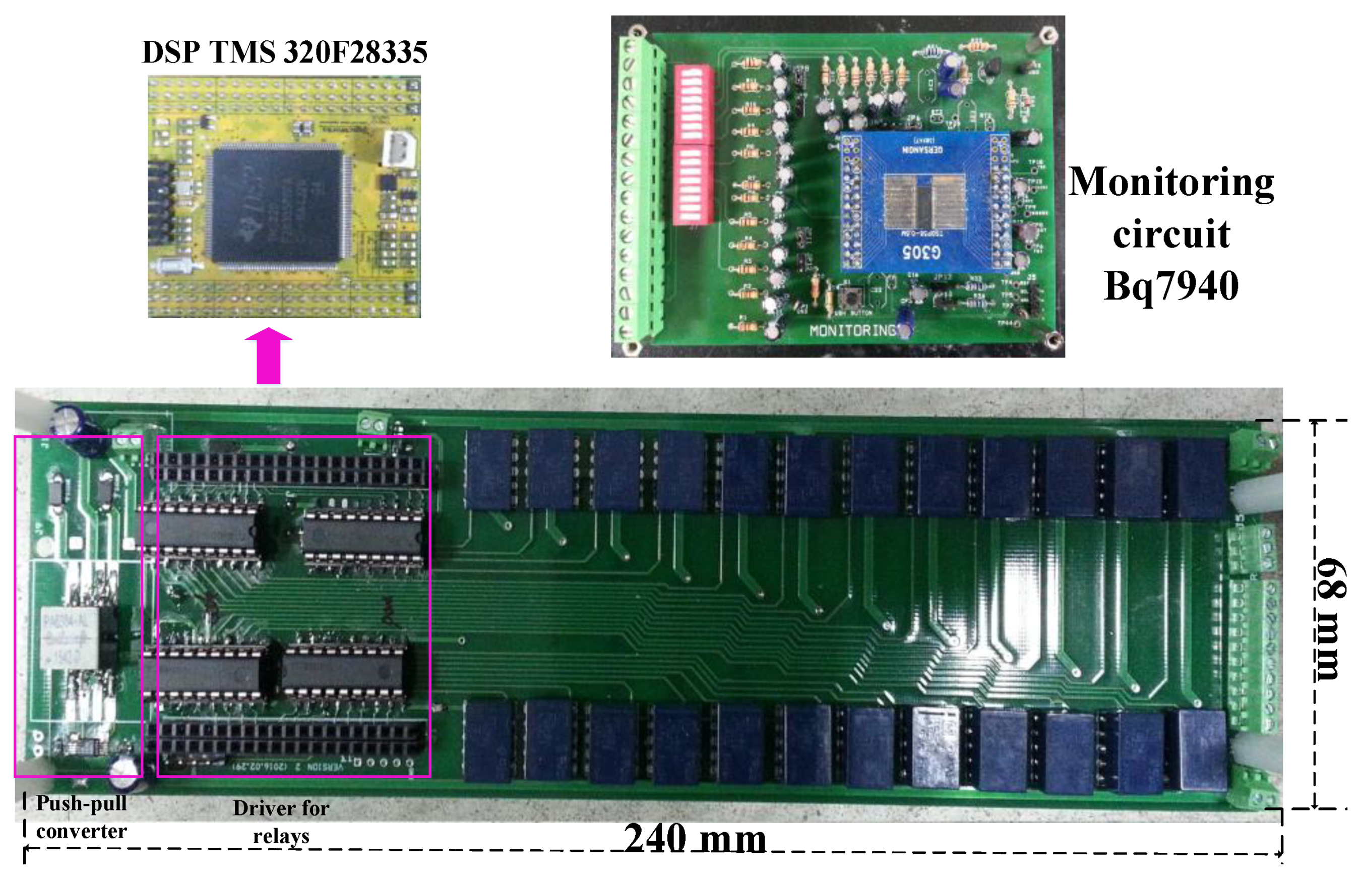
Figure 8.
Experimental setup for twelve lithium-ion battery in a string.

Figure 9.
Experimental waveforms of the push-pull converter (PWM waveforms and the balancing currents).
Figure 9.
Experimental waveforms of the push-pull converter (PWM waveforms and the balancing currents).

Figure 10.
Cell balancing operation of the proposed circuit with twelve Li-ion battery cells.


Table 1.
Comparison of the balancing methods.
| Balancing Method | Component Counts | Characteristics | ||||||
|---|---|---|---|---|---|---|---|---|
| Switch | Photo-Coupler/Pulse Trans. | Diode | Ind. | Cap. | Trans. | |||
| Cell-to-pack [5] | 2N-2 | 2N-2 | 2N-2 | 0 | 0 | m | Requires many steps to balance causing a slow balancing speed, especially for the low voltage cells. | |
| Pack-to-cell [8] | N *+N/2 | N | N | 0 | 0 | N/2 | Requires many steps to balance causing a slow balancing speed, especially for the high voltage cells. | |
| Cell-to-pack-to-cell [9] | 2N * | 2N | 2 | 0 | 0 | 2 | Faster than the cell-to-pack and pack-to-cell methods, but still takes a long time to balance the cells. | |
| Adjacent cell-to-cell | Switched Cap. [10] | 4N * | 4N | 0 | 0 | N | 0 | Impossible to control the balancing current and, hence, the balancing speed is slow. |
| Improved switched Cap. [12] | N+2 * | N+2 | 0 | 0 | N+1 | 0 | ||
| Switched inductor [15] | 2N | 2N | 0 | N | 0 | 0 | ||
| Quasi-resonant [18] | 2N | 2N | 0 | 2N | N | 0 | Possesses a higher efficiency due to soft switching, but the balancing speed is low because it is impossible to control the balancing current. | |
| Direct cell-to-cell | Single Cap. [19] | N+1 * | N+1 | 0 | 0 | 1 | 0 | Impossible to control the balancing current through the capacitor or inductor, hence the balancing speed is slow. |
| Single Ind. [20] | 2N | 2N | 2N | 1 | 0 | 0 | ||
| LC resonant [22] | N+10 * | N+10 | 0 | 1 | 1 | 0 | Highly efficient due to the soft switching. | |
| Multi-winding [24] | 2N * | 2N | 0 | 0 | 0 | 1 | Complex in implementation for many cells. | |
N: number of cells, m: number of module, *: bidirectional switch, Ind.: inductor, Cap.: capacitor, Trans.: transformer.
Table 2.
Component list of the proposed cell balancing circuit.
| Parameters | Manufacturer | |
|---|---|---|
| Push-pull Converter | Transformer | PA6383 |
| MOSFET | AOB290L | |
| Schottky diode | CDBA240LL | |
| Gate driver | TLP250 | |
| Monitoring | Monitoring IC | Bq76940 |
| Shunt resistor | WSR21L000FEA | |
| Cell selection switches | Relay | TQ2-5V |
| Transistor array | ULN2803A | |
Table 3.
Comparison of the proposed cell balancing method for N-cells in the string.
| Cell Balancing Methods | Cost | Balancing Speed | Efficiency | Complexity in Control | Complexity in Implementation |
|---|---|---|---|---|---|
| Cell-to-pack [5] | High | Low | Average | Complex | Simple |
| Pack-to-cell [8] | Low | Low | Low | Complex | Average |
| Cell-to-pack-to-cell [9] | High | Average | Average | Simple | Simple |
| Switched capacitor [10] | High | Low | Low | Simple | Average |
| Improved switched capacitor [12] | Low | Average | Low | Average | Average |
| Switched inductor [15] | High | Low | Low | Simple | Average |
| Quasi-resonant [18] | High | Low | Average | Average | Complex |
| Single capacitor [19] | High | Low | Average | Simple | Simple |
| Single inductor [20] | High | Average | Average | Simple | Average |
| LC resonant [22] | Average | Average | High | Simple | Simple |
| Multi-winding [24] | High | Average | Average | Simple | Complex |
| Proposed method | Low | High | High | Simple | Simple |
© 2020 by the authors. Licensee MDPI, Basel, Switzerland. This article is an open access article distributed under the terms and conditions of the Creative Commons Attribution (CC BY) license (http://creativecommons.org/licenses/by/4.0/).
Share and Cite
MDPI and ACS Style
Pham, V.-L.; Duong, V.-T.; Choi, W. A Low Cost and Fast Cell-to-Cell Balancing Circuit for Lithium-Ion Battery Strings. Electronics 2020, 9, 248. https://doi.org/10.3390/electronics9020248
AMA Style
Pham V-L, Duong V-T, Choi W. A Low Cost and Fast Cell-to-Cell Balancing Circuit for Lithium-Ion Battery Strings. Electronics. 2020; 9(2):248. https://doi.org/10.3390/electronics9020248
Chicago/Turabian StylePham, Van-Long, Van-Tinh Duong, and Woojin Choi. 2020. "A Low Cost and Fast Cell-to-Cell Balancing Circuit for Lithium-Ion Battery Strings" Electronics 9, no. 2: 248. https://doi.org/10.3390/electronics9020248
Note that from the first issue of 2016, this journal uses article numbers instead of page numbers. See further details here.