I/Q Imbalance and Imperfect SIC on Two-Way Relay NOMA Systems
by

Xinji Tian
1, 
Qianqian Li
1,
Xingwang Li
1, 
Hongxing Peng
1,*,
Changsen Zhang
1,
Khaled M. Rabie
2,* and
Rupak Kharel
3 1
School of Physics and Electronic Information Engineering, Henan Polytechnic University, Jiaozuo 454003, China
2
Department of Engineering, Manchester Metropolitan University, Manchester M1 5GDM1 5GD, UK
3
Department of Computing and Mathematics, Manchester Metropolitan University, Manchester M15 6BH, UK
*
Authors to whom correspondence should be addressed.
Electronics 2020, 9(2), 249; https://doi.org/10.3390/electronics9020249
Submission received: 24 December 2019
/
Revised: 26 January 2020
/
Accepted: 1 February 2020
/
Published: 3 February 2020
(This article belongs to the Special Issue Cooperative Communications for Future Wireless Systems)
Abstract
:Non-orthogonal multiple access (NOMA) system can meet the demands of ultra-high data rate, ultra-low latency, ultra-high reliability and massive connectivity of user devices (UE). However, the performance of the NOMA system may be deteriorated by the hardware impairments. In this paper, the joint effects of in-phase and quadrature-phase imbalance (IQI) and imperfect successive interference cancellation (ipSIC) on the performance of two-way relay cooperative NOMA (TWR C-NOMA) networks over the Rician fading channels are studied, where two users exchange information via a decode-and-forward (DF) relay. In order to evaluate the performance of the considered network, analytical expressions for the outage probability of the two users, as well as the overall system throughput are derived. To obtain more insights, the asymptotic outage performance in the high signal-to-noise ratio (SNR) region and the diversity order are analysed and discussed. Throughout the paper, Monte Carlo simulations are provided to verify the accuracy of our analysis. The results show that IQI and ipSIC have significant deleterious effects on the outage performance. It is also demonstrated that the outage behaviours of the conventional OMA approach are worse than those of NOMA. In addition, it is found that residual interference signals (IS) can result in error floors for the outage probability and zero diversity orders. Finally, the system throughput can be limited by IQI and ipSIC, and the system throughput converges to a fixed constant in the high SNR region.
1. Introduction
The demand for new services and data rate has exploded for wireless communication, due to the growth of data traffic in the mobile Internet. To this end, a higher data rate and massive mobile terminal access are required for the 5th Generation (5G) systems [1,2,3]. Many new technologies such as massive multiple-input multiple-output (MIMO), non-orthogonal multiple access (NOMA), millimetre wave and device-to-device communication have been proposed to meet these demands [4]. Among these techniques, NOMA can significantly improve the spectral efficiency and reduce the system latency. Different from the conventional orthogonal multiple access (OMA), NOMA provides services for multiple users on the same resource by using superposition coding at the transmitter and successive interference cancellation (SIC) at the receiver [5,6]. Take an example of downlink: signals from the base station (BS) are superimposed and sent to NOMA users. Users with stronger channel gains decode signals of other users with lower channel gains before decoding their own signals based on the SIC technique [7]. Hence, NOMA can support multiple users with limited resources and improve spectral efficiency, which has attracted considerable attention from academia and industry. For instance, in [8,9], the authors discussed power allocation under various criteria for a downlink NOMA system. In order to improve the system throughput, a network NOMA technique was proposed and analysed for the uplink coordinated multi-point transmission (CoMP) in [10].
Cooperative communications is another solution to mitigate the fading effects of wireless environments [11]. NOMA in cooperative communication systems is commonly referred to as cooperative-NOMA (C-NOMA), which is able to enhance the system reliability [12]. The authors analysed the effect of the power allocation coefficient on the error performance under a one-way relay C-NOMA system in [13]. The authors in [14] presented a new system detection scheme for a one-way relay C-NOMA system, which used the maximal ratio combining (MRC) and SIC to decode signals. Sheng Luo et al. in [15] proposed an adaptive transmission scheme based on a one-way relay C-NOMA network with a dedicated relay, which could temporarily store the received information. Recently, two-way relaying (TWR) has attracted a great deal of research attention because of its ability to achieve higher spectral efficiency in comparison to one-way relaying. It has advantages in the utilization of wireless networks’ resources, improving spectral efficiency and enhancing network quality with regards to network throughput and error rate performance [16]. In [17], the authors proposed a scheme of jointly optimizing power and time allocations to minimize outage probability for a TWR C-NOMA network. To increase the system throughput and to ensure secure communications, the authors in [18] derived closed-form expressions of the ergodic secrecy rates under both non-colluding and colluding eavesdroppers in a TWR C-NOMA network. In order to achieve a balance between spectral efficiency and energy conservation, power allocation was discussed for a TWR C-NOMA system in [19].
According to the principle of NOMA, downlink users with stronger channel gains need to decode signals of other users with lower channel gains before decoding their own signals based on the SIC technique [20]. The NOMA systems with perfect SIC (pSIC) conditions were investigated in most of the above works, which is too idealistic. More in particular, the interference signals (IS) cannot be completely cancelled by SIC in practical applications [21]. In order to study the network with more practical scenarios, the imperfect SIC (ipSIC) condition was assumed for the NOMA system in many literature works. For instance, in [22], the outage probability was derived for NOMA systems with ipSIC in the underlay cognitive radio network. In order to maximize the sum rate for a NOMA network with ipSIC, the authors in [23] optimized the circularity coefficient of the improper Gaussian signalling (IGS) of the downlink NOMA system. Furthermore, Abu Mahady et al. [24] discussed a massive NOMA system in the presence of ipSIC and proposed several schemes to improve the overall system performance.
With the development of RF digital-to-analogue converters directly operating at the channel frequency, digital-intensive polar and quadrature TX architectures have received much attention [25]. The authors in [26] presented a novel digital-intensive hybrid transmitter (TX) architecture, combining conventional in-phase and quadrature (I/Q) with constrained phase modulation. However, it is well known that the RF transceivers of the hardware may not be perfect due to limitations of the technology in the actual communication scenario [27,28,29]. In practice, the hardware is damaged by the following: phase noise I/Q imbalance (IQI) and high power amplifier non-linearities [30,31,32]. In particular, some existing papers have studied the influence of hardware impairments of IQI on the system performance. In [27], a method of a non-iterative blind compensator to mitigate IQI was introduced and investigated by using inactive subcarriers in orthogonal frequency division multiplexing with index modulation (OFDM-IM) data transmission. To investigate the effect of different IQI on the channel estimation and sum rate, Kolomvakis et al. [33] derived the linear minimum mean square error estimator on a MIMO system with large antenna arrays. Furthermore, the expressions of the outage probability were derived by assuming that all the destinations and relay nodes were IQI impaired in [34].
Looking at the open up-to-date technical literature, most works used Rayleigh fading channel, which simplifies all mathematical operations widely. However, when a mirror or line-of-sight (LoS) component exists between the transmitter and the receiver, it cannot capture the change of fading. In addition, the future 5G wireless network will tend to a super-dense deployment, which will lead to more LoS transmissions due to the short propagation distance [35]. Therefore, it is very necessary to study NOMA systems with Rician fading channels [36].
1.1. Contributions
In this paper, we focus on a TWR C-NOMA system with one relay and two users. Two users wish to exchange information via the DF relay in two phases: the uplink multiple access process and the downlink broadcast process. It is worth mentioning that a more practical application scenario is considered in this paper. In other words, we analyse and discuss the performance of a TWR C-NOMA system with IQI and ipSIC conditions over the Rician fading channels. The main contributions of this work are summarized as follows:
- Based on the above works, we investigate the effects of IQI and ipSIC on the performance of a TWR C-NOMA network over the Rician fading channels. It is worth noting that this is a valuable problem for practical system design and analysis. As far as the authors know, although a system with IQI or ipSIC has been studied in some papers, the TWR C-NOMA system model with the condition of IQI and ipSIC under Rician fading channels has not been previously studied.
- We derive analytical expressions for outage probabilities of both the far and near users. The results show that IQI and ipSIC have deleterious effects on the outage performance and residual IS. In order to gain better insights into the system performance, we compare the outage performance of NOMA and OMA for both the far and near users, and the results show that the outage performance of NOMA is better than that of OMA. By comparing Rician and Rayleigh fading channel conditions, it is found that the throughput of our considered system with Rician or Rayleigh fading channels is almost the same in ideal conditions, and IQI and ipSIC have worse effects on the system throughput with Rayleigh fading channels than on Rician.
- We carry out the asymptotic analysis in the high SNR region. Furthermore, based on asymptotic outage probability, the diversity order is derived to analyse the diversity gain of the system. It is demonstrated that residual IS can result in error floors for the outage probability and zero diversity orders.
1.2. Organization
The rest of this paper is organized as follows. In Section 2, we describe the TWR C-NOMA system model in detail. In Section 3, the analytical and asymptotic been expressions of the outage probabilities, diversity order and the system throughput are obtained. Numerical examples of the derived analytical expressions and Monte Carlo simulations are given in Section 4. Finally, the conclusions are presented in Section 5.
1.3. Notations
In this paper, the main notations are shown as follows: is the operator of the conjugate. The notation represents the probability density function (PDF) of the independent variable x, while represents the cumulative density function (CDF) of x. is the expectation operator. represents the operation of summation, and is the zeroth order modified Bessel function of the first kind. represents the conjugation of x. represents that x follow Gaussian distributions. In addition, the list of acronyms used in this paper is listed in Table 1.
2. System Model
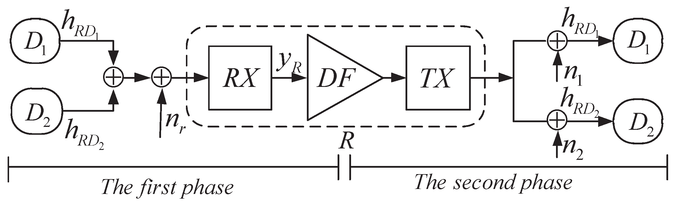
We consider a TWR C-NOMA network over Rician fading channels as depicted in Figure 1, which consists of one relay R and a near user and a far user . It was assumed that there is no direct link between and due to severe shadowing or obstacle. In this case, and can only communicate via a half-duplex (HD) DF relay. We also assumed that the two users and the relay were equipped with a single antenna. In this study, and are modelled as R to link and R to link, respectively.
2.1. I/Q Imbalance Signal Model
Considering IQI at the transmitter (TX) [37], the time domain baseband signal can be obtained as:
where s and denote the baseband IQI-free signal and the IQI impaired signal, respectively; and are the IQI coefficients; and is the conjugation of . As in [37], and are given as follows:
where and are the TX amplitude and phase mismatch, respectively, which follow the Gaussian distribution. Similarly, the time domain baseband representation of the RX IQI impaired signal can be obtained as:
where is referred to as the mirror signal introduced by the IQI. and are the IQI coefficients caused by RX, which can be expressed as:
where and denote the RX amplitude and phase mismatch, respectively, which follow the Gaussian distribution. Therefore, the severity of TX IQI and RX IQI can be expressed as an image rejection ratio, which are defined as follows [38]:
2.2. Signal Model of Joint TX/RX Impaired by IQI
The whole communication process consists of two phases:
(1) The first time slot (up-link NOMA process): Two users send their signals to the relay. The relay receives the signals of the users with RX IQI, and the baseband received signal at the relay is given by:
where denotes the total transmission power of the two users; is the additive white Gaussian noise (AWGN); and are the power allocation coefficients corresponding to and with and , respectively.
The received signal-to-interference plus noise ratio (SINR) for the relay to decode the signal is given by:
where , and denotes the transmit SNR at users.
It was assumed that the signal from can be correctly decoded at the relay. After eliminating by using SIC, the received SINR for the relay to decode the signal is expressed as:
where is recorded as a parameter of ipSIC elimination and and denote pSIC and ipSIC, respectively.
(2) The second time slot (downlink NOMA process): The relay decodes the received signal and broadcasts the signals to the two users. The baseband received signals at with RX IQI denoted by can be represented as:
where denotes the transmission power at the relay. In addition, and are the responding power allocation coefficients for and with and , respectively.
The baseband received signals at is given as:
where and are the AWGN at and with variance , respectively.
It is assumed that neither nor know their own signals. The received SINR for to decode the signal is given by:
where represents the transmit SNR at the users, and the received SINR for to decode is given by:
The received SINR for to decode the signal is given by:
The PDF of the random variable is expressed as [39]:
where is the mean value of , . K is the Rician fading parameter, which represents the ratio of the power of the LoS component to the average power of the non-LoS component. is the zeroth order modified Bessel function of the first kind.
Applying the result of [39], the PDF of can be rewritten as follows:
where , and . Based on this, the CDF of is:
3. Performance Analysis
In this section, we derive analytical expressions for the outage probability of the system under consideration. The asymptotic outage behaviour and diversity orders are also discussed. Then, the system throughput is obtained.
3.1. Outage Probability Analysis
The outage probabilities for the link and the link are denoted by and , respectively.
The outage event of occurs in the following cases: (1) the information cannot be decoded by R; (2) the information cannot be decoded by . Thus, the outage probability of can be written as:
In addition, the outage event of occurs in the following cases: (1) cannot be decoded by R correctly. (2) cannot be decoded by R after R can first decode correctly. (3) cannot be decoded by correctly. (4) cannot be decoded by , while can first decode correctly. Thus, the outage probability of can be written as:
where and , with and denoting the data rate thresholds for users and , respectively.
Theorem 1.
The analytical expression of the outage probability of for the TWR C-NOMA network with IQI and ipSIC can be obtained as:
where with and with .
Proof.
Please see Appendix A. □
Theorem 2.
The analytical expression of the outage probability of for the TWR C-NOMA network with IQI and ipSIC can be obtained as:
where ; , with ; ; ; , with , and , with .
Proof.
Please see Appendix B. □
3.2. Asymptotic Outage Probability Analysis
To get more insight into the outage behaviour of the TWR C-NOMA system with IQI and ipSIC, the formulas of asymptotic outage probabilities at the high SNR region are derived in this subsection.
Proposition 1.
Proposition 2.
3.3. Diversity Orders
In this subsection, the diversity order is analysed, which is defined as [16]:
where and denotes the asymptotic outage probability of , .
By using the definition in (26), the diversity orders for the IQI and ipSIC conditions of both and are respectively derived as follows:
The diversity orders of both and for the considered system with the ideal condition (I/Q balance and pSIC) are derived as:
Remark 1.
An important conclusion from the analysis above is that due to the impact of IQI and residual interference with the use of ipSIC, the diversity orders of and are both zero due to the fixed outage probabilities at the high SNR region. As can be observed, there are error floors for and with IQI and ipSIC.
3.4. System Throughput Analysis
In order to further evaluate the performance of the TWR C-NOMA system, the system throughput is obtained for IQI and ipSIC conditions, as well as for that of the ideal condition, respectively, and given by:
where and represent the target rates at the receiver to decode the desired signals and , respectively.
4. Numerical Examples and Discussions
In this section, we provide numerical illustration of our analytical results through Monte Carlo simulations. Unless otherwise specified, the main parameter values used in all our evaluations are provided in Table 2.
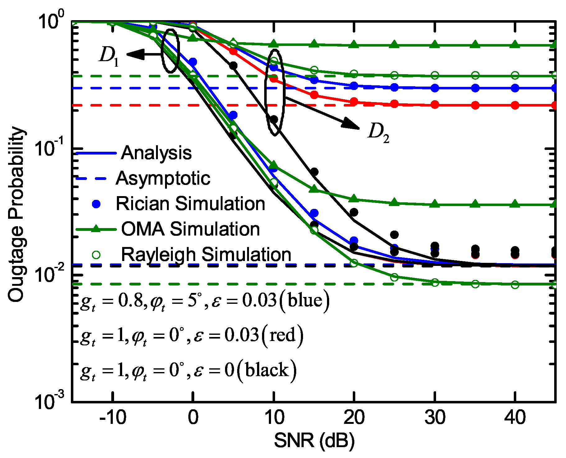
Figure 2 plots the outage probabilities of two users versus transmit SNR with different conditions. The analytical curves for the outage probabilities of the IQI and ipSIC are plotted using (22) and (23). An excellent agreement can be observed between the analytical results and Monte Carlo simulations. We considered five conditions in this simulation: (1) IQI and ipSIC; (2) ONLY ipSIC; (3) NO-IQI and pSIC; (4) OMA; (5) Rayleigh fading channels. In addition, the asymptotic outage probability curves are plotted in accordance using (24) and (25). It is noticed from Figure 2 that the error floors exist for both and . The reason is that the IS result in zero diversity order. The outage performance of the system with IQI is worse than that of the system without IQI, which means that IQI has deleterious effects on the system outage performance. Moreover, the outage performance of with ipSIC is worse than that of the system with pSIC, due to the residual interference caused by ipSIC. It can be seen that the outage performances of and for OMA are lower than NOMA. It is also interesting to note that the outage probability of with ipSIC or with pSIC has the same curves. This is due to the fact that the SIC method is not used in the decoding of the signal of , which is proven by (22). Therefore, the outage performance of the Rayleigh condition is better than the Rician in , and it is worse than the Rician condition in .
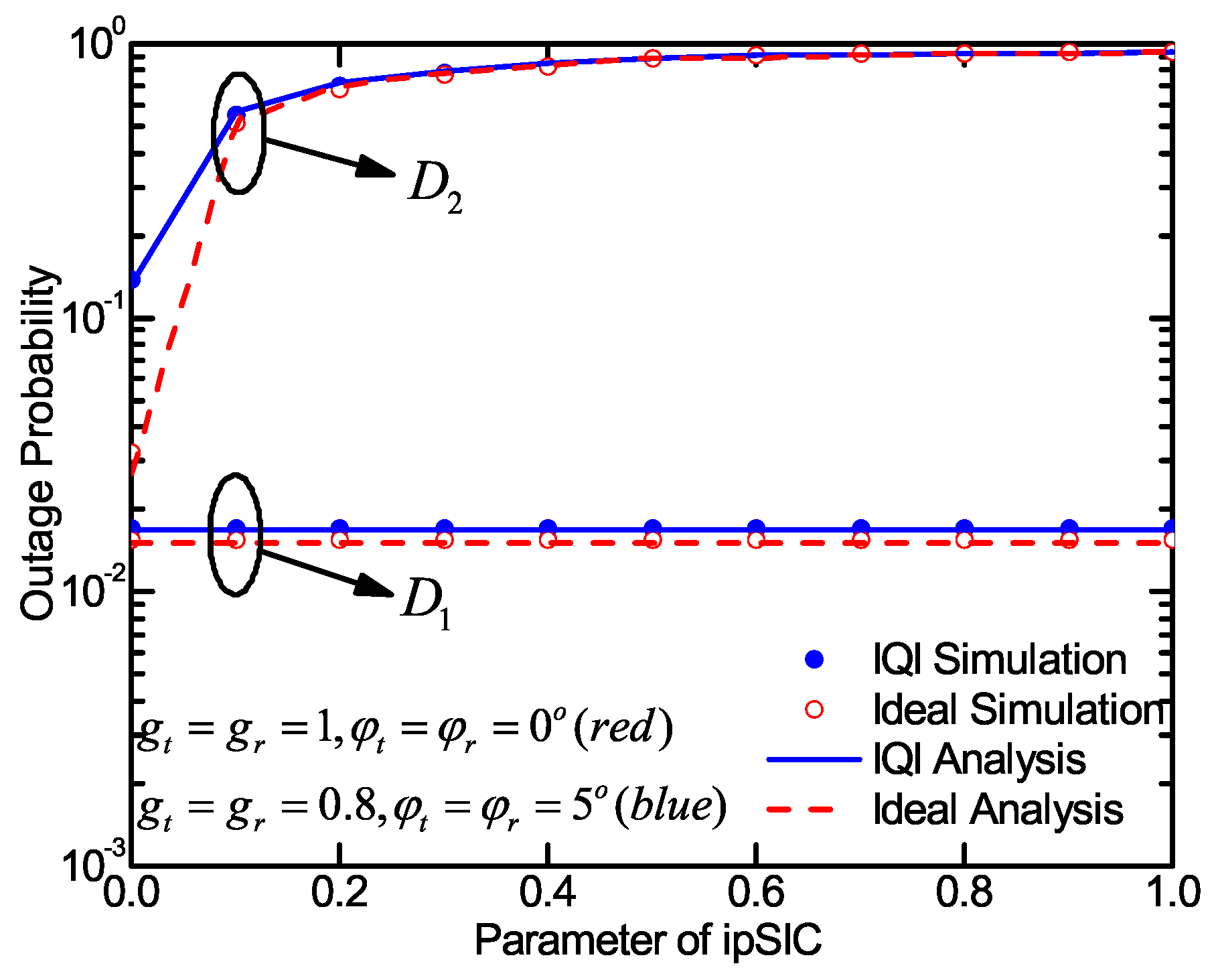
Figure 3 plots the outage probabilities of the two users versus the parameter of ipSIC for the system with IQI and ideal conditions. It is clearly seen that the outage performance of becomes worse with the increase of ipSIC parameter. This is because the residual interference caused by ipSIC is harmful to the outage performance of . In addition, the parameter of ipSIC has no effect on the outage probability of , which is proven by (22). Finally, the outage performances for both and with IQI are worse than that obtained without IQI condition. All in all, IQI reduces the system outage performance.
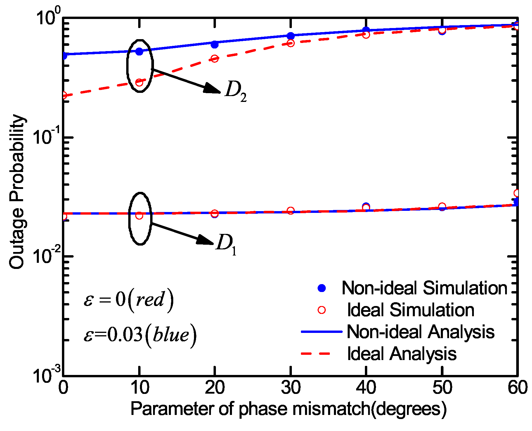
In Figure 4, we show the outage probabilities of and with ipSIC under the different levels of phase mismatch. The outage performances of and deteriorate with the increase of the value of phase mismatch. The greater the gap between the value of the phase mismatch and zero degrees, the greater the adverse effect of the phase mismatch on outage performance.
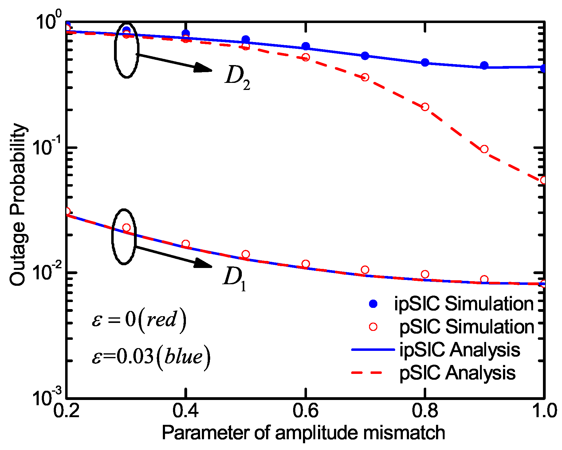
Figure 5 plots the outage probabilities of the two users with respect to the amplitude mismatch with ipSIC and pSIC conditions. It is clearly seen that the closer the amplitude mismatch parameter is to one, the better the outage performance of and becomes. The greater the gap between the value of the amplitude mismatch and one, the greater the harmful effect of the amplitude mismatch on system performance.
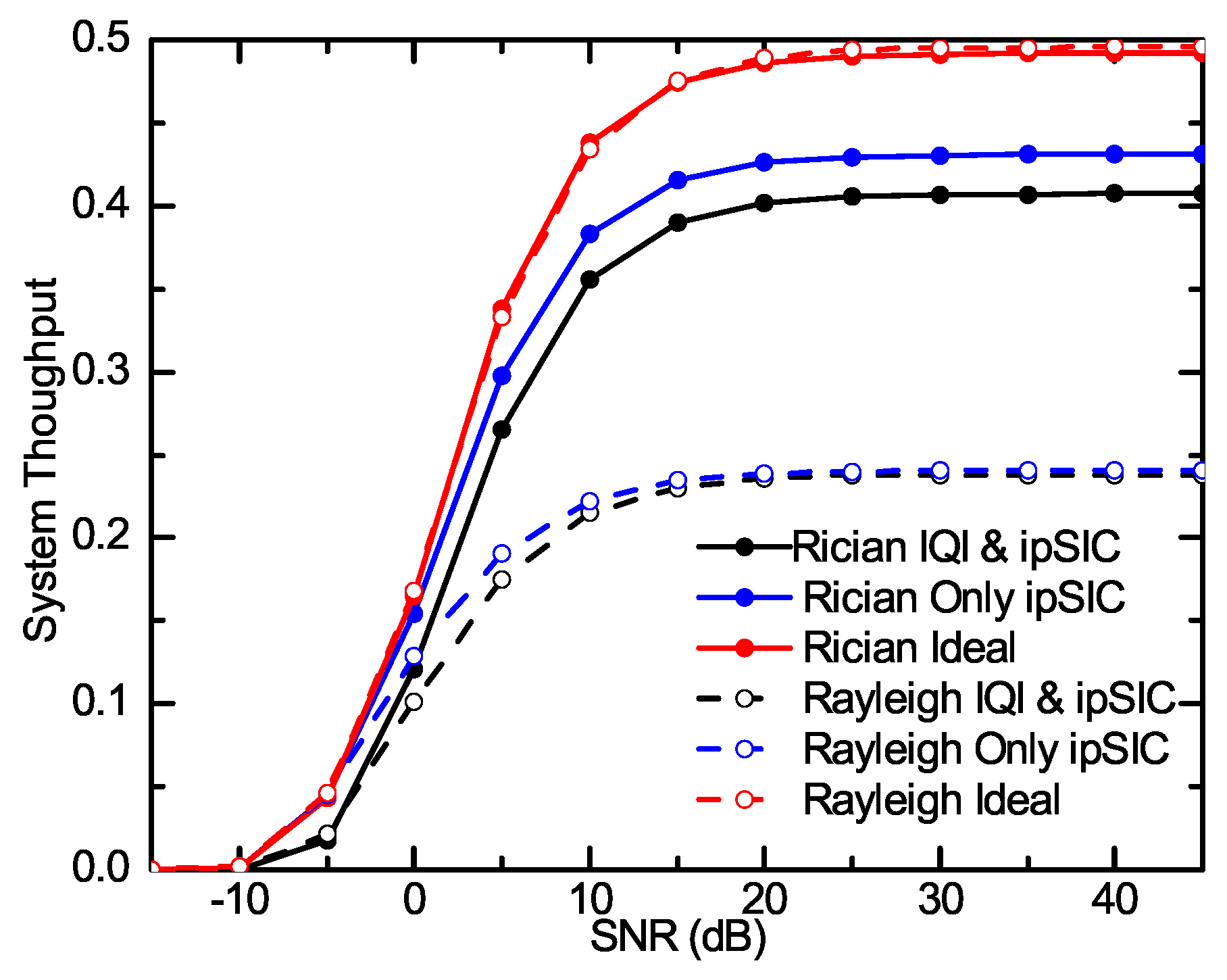
The effects of the three different conditions for the system throughput are evaluated in Figure 6, in which we fix the parameters of IQI as , and the ipSIC parameters as for the IQI and ipSIC conditions. For only the ipSIC condition, we fix the parameters of IQI as , and ipSIC parameters as . For the ideal condition, we use the parameters of IQI as , and ipSIC parameters as . In the SNR range from −10dB to 45dB, the analysis curves of the system throughput with IQI and/or ipSIC condition is always lower than that of the ideal condition. It should be noted that the system throughput enhances as the SNR increase. Moreover, both system throughputs gradually tend to be stable in high SNR region. It can be observed from Figure 6 that the system throughput under two channels is the same in the low SNR region, and at high SNRs, the Rayleigh fading is slightly better than the throughput of the Rician fading channels in the ideal condition. However, in other non-ideal conditions, it is obviously worse than Rician fading channels. Therefore, a conclusion can be obtained that there is almost no difference of the considered system throughput with the ideal condition in the two channel cases, and IQI and ipSIC have worse effects on the system throughput with Rayleigh fading channels than on Rician.
5. Conclusions
In this paper, the performance of a TWR C-NOMA system with IQI and ipSIC over the Rician fading channels was investigated. The analytical expressions of these performance metrics were obtained. In addition, the asymptotic outage behaviour and the diversity order were discussed in the high SNR region. Based on the analytical results, it was shown that the outage performance of the NOMA based system was better than that of OMA. The results revealed that the system outage performance could significantly deteriorate by the IQI and ipSIC. It was also presented that the IS resulted in a zero diversity order in the system. Moreover, the system throughput was found to improve with the increase of SNR, in which it converged to a fixed constant in the high SNR region.
Author Contributions
Conceptualization, X.L., Q.L., C.Z. and X.T.; data curation, X.L. and Q.L.; methodology, X.T., X.L. and Q.L.; software, Q.L.; supervision, X.T., H.P. and H.C.; validation, X.T., X.L., H.P., H.C., K.M.R. and R.K.; formal analysis, X.L., Q.L.; investigation, H.P., H.C., K.M.R. and R.K.; writing, original draft preparation, X.T. and Q.L.; writing, review and editing, X.L., Q.L., K.M.R. and R.K. All authors have read and agreed to the published version of the manuscript.
Funding
This work was supported in part by the Henan Scientific and Technological Research Project under Grant 182102210307, in part by the Fundamental Research Funds for the Universities of Henan Province under Grant NSFRF180309, in part by the Outstanding Youth Science Foundation of Henan Polytechnic University under Grant J2019-4, in part by the Key Scientific Research Projects of Higher Education Institutions in Henan Province under Grant 20A510007.
Conflicts of Interest
The authors declare no conflict of interest.
Appendix A. Proof of Theorem 1
Proof: According to (20), the outage probability for with ipSIC under the IQI condition is given by:
where with and with .
The proof is completed.
Appendix B. Proof of Theorem 2
Proof: According to (21), the outage probability for with ipSIC under IQI condition is given by:
Therein, and can be rewritten as follows:
where ; , with ; .
where ; , with , and , with .
The proof is completed.
References
- Li, X.; Li, J.; Liu, Y.; Ding, Z.; Nallanathan, A. Residual Transceiver Hardware Impairments on Cooperative NOMA Networks. IEEE Trans. Wirel. Commun. 2020, 19, 680–695. [Google Scholar] [CrossRef]
- Li, X.; Liu, M.; Deng, C.; Zhang, D.; Gao, X.C.; Rabie, K.M.; Kharel, R. Joint Effects of Residual Hardware Impairments and Channel Estimation Errors on SWIPT Assisted Cooperative NOMA Networks. IEEE Access 2019, 7, 135499–135513. [Google Scholar] [CrossRef]
- Magueta, R.; Castanheira, D.; Silva, A.; Dinis, R.; Gameiro, A. Hybrid Multi-UserEqualizer for Massive MIMO Millimeter-WaveDynamic Subconnected Architecture. IEEE Access 2019, 7, 79017–79029. [Google Scholar] [CrossRef]
- Ghosh, A.; Maeder, A.; Baker, M.; Chandramouli, D. 5G Evolution: A View on 5G Cellular Technology Beyond 3GPP Release 15. IEEE Access 2019, 7, 127639–127651. [Google Scholar] [CrossRef]
- Kara, F.; Kaya, H. Threshold-Based Selective Cooperative-NOMA. IEEE Commun. Lett. 2019, 23, 1263–1266. [Google Scholar] [CrossRef] [Green Version]
- Li, X.; Li, J.; Li, L. Performance Analysis of Impaired SWIPT NOMA Relaying Networks Over Imperfect Weibull Channels. IEEE Syst. J. 2019, 1–4. [Google Scholar] [CrossRef]
- Deng, C.; Zhao, X.; Zhang, D.; Li, X.; Li, J.; Cavalcante, C.C. Performance Analysis of NOMA-based Relaying Networks with Transceiver Hardware Impairments. KSII Trans. Internet Inf. Syst. 2018, 12, 4295–4316. [Google Scholar]
- Fu, Y.; Salaün, L.; Sung, C.W.; Chen, C.S. Subcarrier and Power Allocation for the Downlink of Multicarrier NOMA Systems. IEEE Trans. Veh. Technol. 2018, 67, 11833–11847. [Google Scholar] [CrossRef]
- Yang, Z.; Xu, W.; Pan, C.; Pan, Y.; Chen, M. On the Optimality of Power Allocation for NOMA Downlinks With Individual QoS Constraints. IEEE Commun. Lett. 2017, 21, 1649–1652. [Google Scholar] [CrossRef]
- Ding, Z.; Dai, H.; Poor, H.V. Relay Selection for Cooperative NOMA. IEEE Trans. Commun. 2016, 67, 5084–5098. [Google Scholar] [CrossRef] [Green Version]
- Ribeiro, F.C.; Dinis, R.; Cercas, F.; Silva, A. Receiver Design for the Uplink of Base Station Cooperation Systems employing SC-FDE Modulations. EURASIP J. Wirel. Commun. Netw. 2015, 2015, 1–17. [Google Scholar] [CrossRef] [Green Version]
- Liau, Q.Y.; Leow, C.Y. Successive User Relaying in Cooperative NOMA System. IEEE Wirel. Commun. Lett. 2019, 8, 921–924. [Google Scholar] [CrossRef]
- Kara, F.; Kaya, H. On the Error Performance of Cooperative-NOMA With Statistical CSIT. IEEE Commun. Lett. 2019, 23, 128–131. [Google Scholar] [CrossRef]
- Abbasi, O.; Ebrahimi, A.; Mokari, N. NOMA Inspired Cooperative Relaying System Using an AF Relay. IEEE Wirel. Commun. Lett. 2019, 8, 261–264. [Google Scholar] [CrossRef]
- Luo, S.; Teh, K.C. Adaptive Transmission for Cooperative NOMA System With Buffer-Aided Relaying. IEEE Commun. Lett. 2017, 21, 937–940. [Google Scholar] [CrossRef]
- Yue, X.; Liu, Y.; Kang, S.; Nallanathan, A.; Chen, Y. Joint beamforming optimisation for NOMA-based wireless powered multi-pair two-way AF and DF relaying networks. IEEE Trans. Commun. 2018, 66, 3784–3796. [Google Scholar] [CrossRef] [Green Version]
- Bae, J.; Han, Y. Joint Power and Time Allocation for Two-Way Cooperative NOMA. IEEE Trans. Veh. Technol. 2019, 68, 12443–12447. [Google Scholar] [CrossRef]
- Zheng, B.; Wen, M.; Wang, C.; Wang, X.; Chen, F.; Tang, J.; Ji, F. Secure NOMA Based Two-Way Relay Networks Using Artificial Noise and Full Duplex. IEEE J. Sel. Areas Commun. 2018, 36, 1426–1440. [Google Scholar] [CrossRef]
- Tang, R.; Cheng, J.; Cao, Z. Energy-Efficient Power Allocation for Cooperative NOMA Systems With IBFD-Enabled Two-Way Cognitive Transmission. IEEE Commun. Lett. 2019, 23, 1101–1104. [Google Scholar] [CrossRef]
- Manglayev, T.; Kizilirmak, R.C.; Kho, Y.H.; Bazhayev, N.; Lebedev, I. NOMA with imperfect SIC implementation. In Proceedings of the IEEE EUROCON 2017–17th International Conference on Smart Technol, Ohrid, Macedonia, 6–8 July 2017; pp. 22–25. [Google Scholar]
- Liu, M.; Song, T.X.; Gui, G. Deep Cognitive Perspective: Resource Allocation for NOMA-Based Heterogeneous IoT With Imperfect SIC. IEEE Internet Things J. 2019, 6, 2885–2894. [Google Scholar] [CrossRef]
- Im, G.; Lee, J.H. Outage Probability for Cooperative NOMA Systems with Imperfect SIC in Cognitive Radio Networks. IEEE Commun. Lett. 2019, 23, 692–695. [Google Scholar] [CrossRef]
- Mahady, I.A.; Bedeer, E.; Ikki, S.; Yanikomeroglu, H. Sum-Rate Maximization of NOMA Systems Under Imperfect Successive Interference Cancellation. IEEE Commun. Lett. 2019, 23, 474–477. [Google Scholar] [CrossRef]
- Kolomvakis, N.; Matthaiou, M.; Coldrey, M. Outage probability under I/Q imbalance and cascaded fading effects. IEEE Trans. Commun. 2016, 64, 3039–3051. [Google Scholar] [CrossRef] [Green Version]
- Parikh, V.K.; Balsara, P.T.; Eliezer, O.E. All digital-quadrature-modulator based wideband wireless transmitters. IEEE Trans. Circuits Syst. 2009, 56, 2487–2497. [Google Scholar] [CrossRef]
- Zhang, Y.P.; Li, X.J.; Phang, T.Y. A study of dual-mode bandpass filter integrated in BGA package for single-chip RF transceivers. IEEE Trans. Adv. Packag. 2006, 29, 354–358. [Google Scholar] [CrossRef]
- Solanki, S.; Upadhyay, P.K.; da Costa, D.B.; Bithas, P.S.; Kanatas, A.G.; Dias, U.S. Joint Impact of RF Hardware Impairments and Channel Estimation Errors in Spectrum Sharing Multiple-Relay Networks. IEEE Trans. Commun. 2018, 66, 3809–3824. [Google Scholar] [CrossRef]
- Li, X.; Liu, M.; Deng, D.; Li, J.; Deng, Ch.; Yu, Q. Power Beacon Assisted Wireless Power Cooperative Relaying using NOMA with Hardware Impairments and Imperfect CSI. AEU - Int. J. Electron. Commun. 2019, 108, 275–286. [Google Scholar] [CrossRef]
- Teodoro, S.; Silva, A.; Dinis, R.; Barradas, F.M.; Cabral, P.M.; Gameiro, A. Theoretical Analysis of Nonlinear Amplification Effects in Massive MIMO Systems. IEEE Access 2019, 7, 172277–172289. [Google Scholar] [CrossRef]
- Tian, X.; Li, Q.; Li, X.; Zhang, H.; Rabie, K.; Cavalcante, C.C. Performance Analysis of Two-Way Relay NOMA Systems with Hardware Impairments and Channel Estimation Errors. Ksii Trans. Internet Inf. Syst. 2019, 13, 5370–5493. [Google Scholar]
- Li, X.; Huang, M.; Li, J.; Yu, Q.; Rabie, K.; Cavalcante, C.C. Secure Analysis of Multi-Antenna Cooperative Networks with Residual Transceiver HIs and CEEs. IET Commun. 2019, 13, 2649–2659. [Google Scholar] [CrossRef] [Green Version]
- Li, X.; Liu, M.; Deng, C.; Mathiopoulos, P.T.; Ding, Z.; Liu, Y. Full-Duplex Cooperative NOMA Relaying Systems with I/Q Imbalance and Imperfect SIC. IEEE Wirel. Commun. Lett. 2019, 9, 1–1. [Google Scholar] [CrossRef]
- Mohajeran, S.A.; Sadough, S.M.S. On the Interaction Between Joint Tx/Rx IQI and Channel Estimation Errors in DVB-T Systems. IEEE Syst. J. 2018, 12, 3271–3278. [Google Scholar] [CrossRef]
- Kolomvakis, N.; Coldrey, M.; Eriksson, T.; Viberg, M. Massive MIMO Systems With IQ Imbalance: Channel Estimation and Sum Rate Limits. IEEE Trans. Commun. 2017, 65, 2382–2396. [Google Scholar] [CrossRef]
- Beaulieu, N.C.; Hemachandra, K.T. Novel Representations for the Bivariate Rician Distribution. IEEE Trans. Commun. 2011, 59, 2951–2954. [Google Scholar] [CrossRef]
- Rice, S.O. Mathematical analysis of random noise. Bell Syst. Tech. J. 1944, 23, 282–332. [Google Scholar] [CrossRef]
- Li, J.; Matthaiou, M.; Svensson, T. I/Q Imbalance in Two-Way AF Relaying. IEEE Trans. Commun. 2014, 62, 2271–2285. [Google Scholar] [CrossRef]
- Selim, B.; Muhaidat, S.; Sofotasios, P.C.; Sharif, B.S.; Stouraitis, T.; Karagiannidis, G.K.; Al-Dhahir, N. Performance Analysis of Non-Orthogonal Multiple Access Under I/Q Imbalance. IEEE Access 2018, 6, 18453–18468. [Google Scholar] [CrossRef]
- Li, X.; Wang, Q.; Peng, H.; Zhang, H.; Do, D.T.; Rabie, K.; Cavalcante, C. A unified framework for HS-UAV NOMA networks: Performance analysis and location optimization. IEEE Access 2019, 8, 13329–13340. [Google Scholar] [CrossRef]
Figure 1.
System model.

Figure 2.
Outage probability versus the transmit SNR of the proposed TWR C-NOMA system for and with data rate thresholds and .
Figure 2.
Outage probability versus the transmit SNR of the proposed TWR C-NOMA system for and with data rate thresholds and .

Figure 3.
Outage probability versus the parameter of ipSIC for the system with IQI and ideal conditions.
Figure 3.
Outage probability versus the parameter of ipSIC for the system with IQI and ideal conditions.

Figure 4.
Outage probability versus the parameter of phase mismatch for the system with ipSIC and pSIC conditions.
Figure 4.
Outage probability versus the parameter of phase mismatch for the system with ipSIC and pSIC conditions.

Figure 5.
Outage probability versus the amplitude mismatch for the system with ipSIC and pSIC conditions.
Figure 5.
Outage probability versus the amplitude mismatch for the system with ipSIC and pSIC conditions.

Figure 6.
System throughput versus the transmit SNR of the proposed TWR C-NOMA system for and with data rate thresholds and .
Figure 6.
System throughput versus the transmit SNR of the proposed TWR C-NOMA system for and with data rate thresholds and .


Table 1.
Table of acronyms.
| Acronyms | Definition |
|---|---|
| NOMA | Non-orthogonal multiple access |
| UE | User devices |
| OMA | Orthogonal multiple access |
| ipSIC | Imperfect successive interference cancellation |
| pSIC | Perfect successive interference cancellation |
| Probability density function | |
| CDF | Cumulative density function |
| 5G | 5th Generation |
| TWR C-NOMA | Two-way relay cooperative NOMA |
| DF | Decode-and-forward |
| BS | Base station |
| COMP | Coordinated multi-point transmission |
| MRC | Maximal ratio combining |
| IGS | Improper Gaussian signalling |
| TX | Transmitter |
| RX | Receiver |
| IQI | In-phase and quadrature imbalance |
| OFDM-IM | Orthogonal frequency division multiplexing with index modulation |
| LoS | Line-of-sight |
| AWGN | Additive white Gaussian noise |
| SNR | Signal-to-noise ratio |
| SINR | Signal-to-interference plus noise ratio |
| IS | Interference signals |
| MIMO | Multiple-input multiple-output |
Table 2.
Table of parameters used for numerical results.
| Monte Carlo Simulations Repeated | Iterations |
|---|---|
| Power allocation coefficients of NOMA | , , and |
| Targeted data rates | , |
| The distance between R and or | , |
| Noise power | |
| The parameters of ipSIC | |
| Ideal RF front end | , |
| The parameters of IQI | , |
© 2020 by the authors. Licensee MDPI, Basel, Switzerland. This article is an open access article distributed under the terms and conditions of the Creative Commons Attribution (CC BY) license (http://creativecommons.org/licenses/by/4.0/).
Share and Cite
MDPI and ACS Style
Tian, X.; Li, Q.; Li, X.; Peng, H.; Zhang, C.; Rabie, K.M.; Kharel, R. I/Q Imbalance and Imperfect SIC on Two-Way Relay NOMA Systems. Electronics 2020, 9, 249. https://doi.org/10.3390/electronics9020249
AMA Style
Tian X, Li Q, Li X, Peng H, Zhang C, Rabie KM, Kharel R. I/Q Imbalance and Imperfect SIC on Two-Way Relay NOMA Systems. Electronics. 2020; 9(2):249. https://doi.org/10.3390/electronics9020249
Chicago/Turabian StyleTian, Xinji, Qianqian Li, Xingwang Li, Hongxing Peng, Changsen Zhang, Khaled M. Rabie, and Rupak Kharel. 2020. "I/Q Imbalance and Imperfect SIC on Two-Way Relay NOMA Systems" Electronics 9, no. 2: 249. https://doi.org/10.3390/electronics9020249
Note that from the first issue of 2016, this journal uses article numbers instead of page numbers. See further details here.