Multi-Objective Optimization of Task-to-Node Assignment in Opportunistic Fog RAN


Department of Electrical and Electronic Engineering, Auckland University of Technology, Private Bag 92006, Auckland 1142, New Zealand
*
Author to whom correspondence should be addressed.
Electronics 2020, 9(3), 474; https://doi.org/10.3390/electronics9030474
Submission received: 11 February 2020
/
Revised: 9 March 2020
/
Accepted: 9 March 2020
/
Published: 12 March 2020
(This article belongs to the Special Issue Opportunistic Networks)
Abstract
:The opportunistic fog radio access network (OF-RAN) is a promising RAN architecture proposed for next-generation cellular networks. OF-RAN extends the current fog RAN (F-RAN) architecture by introducing virtual fog access points (v-FAPs) that can be formed on-demand by a set of resourceful end-user devices available in an opportunistic manner. These devices in the v-FAP collaboratively serve as the service nodes to a resource-limited local client by performing resource-demanding processing tasks on its behalf. Hence, appropriately assigning the client task to the service nodes of the v-FAP, i.e., task-to-node assignment (TNA), is a fundamental problem in OF-RAN. This paper formulates and solves the TNA as a multi-objective optimization problem, with the goals of minimizing energy and latency of the v-FAP, while maximizing fairness (or load balancing) amongst its service nodes by minimizing their maximum load.
1. Introduction
With the emergence of the Internet of Things (IoT), where a large number of smart devices will need to communicate with each other, next-generation cellular networks will play a pivotal role in providing fast and reliable communication services, not only to humans but also the IoT devices [1]. The notion of a cloud radio access network (Cloud-RAN) was developed to support these goals by enabling flexible splitting of RAN functionalities between radio access points (RAPs) and the cloud, based on the availability of cloud resources [2,3]. However, the Cloud-RAN may suffer from a heavy workload in its centralized baseband unit (BBU) pool, coerced backhaul capacity and difficulty in meeting the low latency requirements of delay-sensitive applications [4,5]. In order to address these challenges, the fog radio access network (F-RAN) was proposed. Unlike Cloud-RAN, the F-RAN utilizes resources from devices on the network edge to provide localized RAN services to its end-users [6]. The F-RAN deploys geo-distributed fog access points (FAP), which serve the user devices directly or with the assistance of other devices. The F-RANs, however, have only considered using dedicated fog servers, existing remote radio heads (RRHs) or macrocell base stations extended with fog functionalities such as FAPs. They do not leverage the presence of other edge devices such as WiFi access points, femtocell base stations and resourceful user devices such as high-end smart phones, tablets and smart TVs to collectively perform the role of the FAP [7].
Recently, we proposed a novel opportunistic F-RAN (OF-RAN) [8], conceived from the concepts of F-RAN and opportunistic networks (oppnet). The latter is a type of mission-oriented ad-hoc network formed to utilize local resources opportunistically [9]. It composes a small set of ‘seed’ nodes, which, when required to accomplish a mission, can recruit locally available ‘helper’ nodes to establish an oppnet for that mission. The FAPs of the current F-RAN resemble the seed nodes of our proposed OF-RAN architecture. Each seed node can recruit local resourceful user devices as helper nodes, which it manages collectively as a virtual FAP (v-FAP). Each v-FAP can be formed dynamically by the seed node to serve a resource-limited user or IoT device. In this paper, these resource-limited devices and helper nodes are referred to as the clients and service nodes, respectively. The processing to be done by a v-FAP for a client is referred to as a service task, which previously would have been performed by the dedicated FAPs in F-RAN or by the cloud in C-RAN.
Figure 1 illustrates an OF-RAN with three v-FAPs (shaded in blue), each serving a client through a seed node and multiple service nodes. Initially, the client sends a service request to the fog-enabled RRH (as in current F-RAN). If the RRH is too busy to serve the client, it can instruct a local seed node to serve on its behalf. If the seed node does not have sufficient resources to serve the client, the seed node can form a v-FAP by recruiting local resourceful user devices as service nodes. Considering real-world heterogeneity in the service node’s resource capacities and client task’s resource demands, a significant problem that arises in OF-RAN is the proper assignment of the client task to service nodes in a v-FAP, i.e., task-to-node assignment (TNA), which best meets the desired performance objectives.
In one of our previous works [10], a similar TNA problem was solved as a single-objective optimization problem with the fairness objective of balancing the workloads at the service nodes. However, in the real-world, there are often multiple objectives to be considered when finding the best possible solution. Hence, the main contributions of this paper are as follows: we reconsider the TNA problem in our OF-RAN and present a novel solution approach that balances the trade-offs among conflicting objectives. More specifically, we formulate and solve the TNA problem as a tri-objective optimization problem that seeks to minimize energy and latency of the v-FAP, while maximizing fairness amongst its service nodes by balancing their resources consumption.
The rest of the paper is organized as follows. Section 2 reviews the related literature. Section 3 presents the system model and formulates the problem. Section 4 presents the designed optimization framework for our specific TNA problem. The simulation environment and results are discussed in Section 5 and Section 6, respectively. Finally, Section 7 concludes the paper.
2. Related Works
In [11], the authors formulated the sensor placement and transmit power assignment in a wireless sensor network as a multi-objective optimization problem. Using the Multi-Objective Evolutionary Algorithm based on Decomposition (MOEA/D) and Non-dominated Sorting Genetic Algorithm (NSGA) II, they obtained the optimal location and transmit power of sensors that maximized the network coverage and lifetime. The results showed that MOEA/D outperformed NSGA II in terms of quantity and quality of solutions. However, the authors only focused on meeting the sensing coverage and lifetime requirements. They did not consider the connectivity to the sink, which may require some sensors to relay data for others, incurring a further energy cost that can impact their lifetime. In real-world network design, the different roles of nodes and the costs of using them should be considered (as in our work herein).
In [12], the authors used queuing models to analyze the trade-offs between energy consumption, delay and payment cost for mobile devices (MDs) when they perform or offload computation-intensive tasks to the cloud or nearby fog nodes. A multi-objective optimization problem was formulated and solved using the interior-point method to determine the optimal offloading probability and transmission power for each MD with the goals of minimizing energy consumption, delay and payment cost. The authors in [13] aimed to minimize energy and delay in computation offloading from MDs to mobile edge computing (MEC) servers. A method for chromosome encoding was proposed, and NSGA-II was used to obtain pareto-optimal offloading decisions. Similarly, a semidefinite relaxation algorithm was presented in [14] to optimize offloading decisions using MD’s processor frequency and channel quality with the servers which can impact both energy and delay performances. All of these works used dedicated fog or MEC servers and did not exploit computing resources that may lie close to the MDs. Not considering the servers’ workload in offloading decisions may also result in overloaded servers that become points of failure. Moreover, the solution quality and real-timeliness of the heuristics used are not guaranteed, as a large number of iterations is often required for reaching a satisfying near-optimal solution.
In [15], a MOEA/D approach was presented to solve an asset-based weapon-target assignment problem. The asset refers to some valuable entity to be protected against attacks by some targets, and weapons are used to annihilate the targets. The optimization goal is to maximize the asset value and minimize the weapon consumption. Simulation results showed that the proposed approach performs well in terms of convergence and efficiency. The MOEA/D is known to find optimal solutions within reasonable time for other discrete optimization problems such as the Traveling Salesman and Knapsack problems [16].
The authors in [17] presented a fog-based solution that offers computation and storage services for IoT applications. It aims to reduce the network latency of these applications by placing services into fog nodes close to the IoT devices. Multi-objective optimization techniques, MOEA/D, NSGA II, and Weighted Sum Genetic Algorithm (WSGA) II, were used to obtain optimal fog service placements that minimize network latency and maximize service coverage and resource utilization of the fog nodes. The results showed that MOEA/D and NSGA II outperformed WSGA II in all three objectives. However, the authors did not address the fairness issue, as the workload among the fog nodes was not considered.
3. System Modeling and Problem Formulation
This section presents the v-FAP system model for the proposed OF-RAN and formulates the TNA problem as a tri-objective optimization problem.
3.1. System Modelling
Figure 2 shows an OF-RAN seed node that lies in the coverage of a fog-enabled RRH and is surrounded by resourceful user devices that it can recruit as service nodes to form a v-FAP (shaded in blue) for a resource-limited user or IoT client device with computation-intensive and delay-sensitive tasks to be performed. The communication links between the seed node and RRH can be wired or wireless, while only wireless links exist between the seed node and service nodes, between the seed node and client and between the client and RRH. As the RRH coordinates the transmission and reception between various nodes involved in the v-FAP formation, we consider the communication environment as an interference-limited environment.
As shown in Figure 2, a client wishing to be served firstly sends a request (1) including its task requirements to its associated RRH. If the RRH is busy, it sends a notification (2) to a seed node located near the client to serve on its behalf, which is also received by the client. The client then sends its tasks to the seed node (3). Based on the received tasks and task requirements, the seed node decides if it can serve the client on its own or should enlist the resources of its neighboring user devices by recruiting them as service nodes to collectively serve in a v-FAP. In the latter case, the seed node determines an optimal way of assigning the client’s tasks to the service nodes so that the performance objectives are achieved. An optimal assignment defines the set of service nodes that constitute the v-FAP and the task(s) that each service node will perform. Based on the optimal assignment, the seed node sends the received tasks to the service nodes for processing (4), collates the processed tasks from the service nodes (5) and forwards them to the client (6).
We consider a seed node with resourceful user devices in its neighborhood that can be recruited as service nodes. We also consider a client with tasks to be performed externally. To reflect real-world scenarios, both the service nodes and tasks are assumed to be heterogeneous, each having different resource capacities and resource demands, respectively. Two resource types are considered: energy resource and time resource, which refer to the amount of energy available and time available, respectively, in a service node to serve the client.
The energy demand for each task depends not only on its size (in bytes) and complexity (in central processing unit (CPU) cycles), but also which service node the task has been assigned to and the energy required by the assigned service node to perform the task, i.e., the task’s energy demand can vary with different node assignment. A service node consumes energy for receiving, processing and transmitting a task. Thus, the total energy demand of a particular task in the service node, denoted as, can be given by:
where and ; is the energy required by node to receive task from the seed node; is the energy required by the node to process the task; and is the energy required by the node to transmit the processed task to the seed node. , and can be further defined as:
where (in joules per byte) is the energy required by the node to receive one byte of task from the seed node; (in joules per CPU cycle) is the energy required by the node to process a period of one CPU cycle; (in joules per byte) is the energy required by the node to transmit one byte of processed task to the seed node; and represent the size of the task received and processed task transmitted, respectively (in bytes); and is the processing complexity of the task in CPU cycles.
Similarly, the time demand for each task consists of processing time and communication time. Thus, the total time demand of a particular task in the service node, denoted as, can be given by:
where is the time required by the node to receive the task from the seed node; is the time required by the node to process the task; and is the time required by the node to transmit the processed task to the seed node. , and can be further defined as:
where is the processing speed of the node in CPU cycles per second; and represent the data rate of communication from the seed node to the node and from the node to the seed node, respectively, in bits per second, which can be given by the Shannon-Hartley capacity theorem using a known channel bandwidth and received signal-to-noise ratio [18].
3.2. Problem Formulation
For a given number of service tasks and number of service nodes, denote as the set of possible TNAs, as the cardinality of set (i.e., ) and as the TNA of where . Figure 3 shows an example of TNA, denoted by , for and . is given as an binary matrix where a non-zero entry at an column and row indicates a certain task is assigned to an node. If is an element of the TNA matrix, then constraints Equations (5) and (6) for an task and node, respectively, must be satisfied in defining each TNA.
The TNA is formulated as a tri-objective problem with the goals of minimizing energy consumption and service latency of the v-FAP while maximizing fairness (load balancing) amongst its service nodes by minimizing their maximum load. In this work, the load of a service node is expressed as a fraction of its resource capacity consumed for performing its assigned task(s). A service node with a high resource capacity can thus take on a high absolute load and vice-versa.
Each node is specified with and , representing the per unit cost of using its energy and time, respectively. can be made inversely proportional to the available energy capacity of the node, i.e., the higher its energy capacity, the lower the cost of using its energy. Similarly, can be made inversely proportional to the processing and communication speed of the node, i.e., the higher its processing and communication speed, the lower the cost of using its time.
For a particular client, the total energy cost of using the TNA from a set of possible TNAs for assigning tasks to nodes in a v-FAP is given by:
where is the sum of the energy demand by the set of task(s) assigned to the node, is the set of total energy demands by each task in , with as defined in Equation (1), and is the total available energy in the node to serve its client.
Similarly, the total time cost of using the TNA from a set of possible TNAs for assigning tasks to nodes in a v-FAP is given by:
where is the sum of the time demand by the set of task(s) assigned to the node, ,...,is the set of total time demands by each task in , with as defined in (3), and is the total available time of the node to serve its client.
The maximum node usage cost , i.e., the maximum cost of using a service node in the TNA to serve a client, is given by:
where and are normalization factors for scaling the cost into the interval [0, 1]. For an service node, the per unit costs of using its energy () and its time () are inversely proportional to its available energy and processing/communication speed, respectively. also reflects the highest fractional use of a service node’s resources, i.e., the maximum load on a service node in the TNA.
In order to select an optimal TNA that not only minimizes and but also maximizes fairness amongst the service nodes by minimizing their maximum load, our tri-objective optimization problem can be defined as:
4. MOEA/D Framework for Solving the TNA Problem
Since our TNA problem is dealing with conflicting objectives, it cannot be solved by optimizing each objective individually while treating all other objectives as constraints, as there is no single solution that can optimize all objectives simultaneously. Hence, we designed a solution framework based on the MOEA/D algorithm, which gives a promising (pareto-optimal) set of solutions with reasonable tradeoffs between the objectives [19], i.e., all solutions in the set are non-dominant, and the decision-maker can select the best TNA from the set based on the desired outcome.
A multi-objective problem (MOP) can be defined as:
where is the number of objectives in our problem, and parameters , and , are as defined in Section 3.2. Here, : where is the decision variable space which maps to the objective function space . Hence, is the attainable objective set, while , and correspond to , and in (12), respectively.
4.1. Decomposition
It is known that the pareto-optimal solution to any MOP can be the optimal solution to a number of scalar (single objective) optimization sub-problems whose objective is the weighted aggregation of all the ‘s [20]. The decomposition of an MOP into a set of sub-problems is commonly based on the weighted-sum and Tchebycheff approaches. We adopted the Tchebycheff approach as it produces more diverse pareto fronts, including convex, concave, mixed and other geometries. The approach uses a weight vector consisting of weights (one for each objective) for the sub-problem where and . Our MOP is decomposed into sub-problems. For each sub-problem, different weights are applied to the objective function as shown in Equation (14). is the solution variable (chromosome) for the sub-problem representing the TNA to be optimized, is the set of reference points holding the minimum of each of the objectives values ‘s in the decision variable space, i.e., , is the set of weight vectors for the sub-problems and determines the fitness of each in by obtaining the maximum of all weighted ‘s for that assignment. The fittest assignment is then the one with the minimum fitness value:
4.2. MOEA/D Framework
An initial internal population () consisting of possible TNAs (parent chromosomes) is generated. For each of the sub-problems, a set of closest neighboring sub-problems is determined based on shortest Euclidean distances between its weight vector and those of other () sub-problems. Two parent chromosomes and are then randomly selected from the solutions (TNAs) of the neighboring sub-problems to generate an offspring or new solution (new TNA). An update phase follows, where the reference point set is updated if the offspring results in a new minimum of each of the objectives values ‘s, and the closest neighbors of the sub-problem are updated if the offspring provides a better solution in terms of fitness.
For every generation, is also updated to reflect the best solutions found so far for each sub-problem. All non-dominated solutions found during the search are placed in an external population (). A solution is said to dominate another solution if and only if it is equal to or better than in all objectives and there is at least one objective where is strictly better, i.e., is non-dominated by . Thus, in a set of non-dominated solutions, no solution can dominate the others in all objectives. The is updated for every generation, and the pareto front is plotted using the final set of non-dominated solutions. Algorithm 1 shows our MOEA/D framework for the TNA problem.
| Algorithm 1 MOEA/D framework for the TNA problem |
| 1: Input: |
| 2: TNA parameters (, ,); |
| 3: : population size and number of sub-problems; |
| 4: : neighborhood size; |
| 5: set of weight vectors for the sub-problems; |
| 6: : maximum number of generations (beyond which no further addition of non-dominated solutions to the is normally observed) |
| 7: Output: |
| 8: Step 1) Initialization |
| 9: Set =; ; ; |
| 10: Generate an initial randomly subject to the constraints in Equations (5) and (6); |
| 11: Determine the closest neighborhood for each of sub-problems; |
| 12: Step 2) Reproduction and update |
| 13: for do |
| 14: Randomly select two closest neighbor solutions and generate a new solution using the genetic operators |
| 15: Use to update , closest neighbor solutions, and |
| 16: end |
| 17: Step 3) Stopping criterion |
| 18: if then |
| 19: Stop and output ; |
| 20: else |
| 21: Increment and go to Step 2) |
| 22: end |
4.2.1. Chromosome encoding
In MOEA/D, the solutions are represented as chromosomes. For our specific TNA problem, the TNAs are encoded as chromosomes, and then MOEA/D is employed to evolve them into optimal TNAs subject to our energy, latency and fairness (load balancing) objectives. Given the discrete nature of our problem, decimal encoding is introduced to express the TNAs as chromosomes. Each chromosome (TNA) has a certain length (number of service tasks) and carries multiple genes (service nodes). Therefore, each gene’s value is the index of a service node, while its locus (position) in the chromosome denotes the index of a service task assigned to the service node represented by the gene.
Figure 4 shows an example of our chromosome encoding for the case of 4 service nodes and 8 service tasks (, ). The encoded chromosome represents a specific TNA, where tasks 1 and 4 ( and ) are assigned to node 1 (); tasks 2, 3 and 8 are assigned to node 2; tasks 6 and 7 are assigned to node 3 and finally, task 5 is assigned to node 4.
4.2.2. Crossover Operator
In order to evolve the chromosomes (TNAs), the MOEA/D applies a crossover operator to a pair of parent chromosomes and generates an offspring (new TNA). We consider three crossover operators: one-point, two-point and uniform crossover as described below, and then determine which is the most appropriate in the next section.
- One-point crossover: Two parent chromosomes ( of length M are selected, and a random crossover point is chosen between 1 and . Each chromosome is then sliced into two segments which are exchanged to produce offspring, from which an offspring is randomly selected.
- Two-point crossover: The process is similar to one-point crossover, except two instead of one random crossover points are chosen for segmenting the chromosomes.
- Uniform crossover: Unlike the above, offspring here are produced from an exchange of genes uniformly selected from two parent chromosomes: from odd-index locus of and even-index locus of , and vice-versa; from which an offspring is randomly selected.
5. Simulation Environment
The designed framework is implemented in MATLAB and evaluated under varying number of service nodes () and service tasks (). The impacts of different crossover operators on the produced solutions are also investigated. Finally, a comparison is made with solutions obtained using the non-dominated sorting genetic algorithm (NSGA) II, which is a competing alternative to MOEA/D. All obtained solutions (TNAs) are evaluated for their incurred objective costs, i.e., total energy cost , total time (latency) cost and maximum node usage cost , as defined by Equations (7), (9) and (11), respectively.
The cost of a TNA reflects the maximum load that it assigns to its service nodes. Thus, minimizing is also maximizing fairness (load balancing) amongst the service nodes in a TNA. However, instead of , it is more intuitive to show the standard deviation (S.D.) of the loads between service nodes in each TNA in order to reflect fairness. The solutions obtained are plotted as a three-dimensional pareto-front, one dimension for each objective. All objective costs on the pareto-front are normalized to the interval [0,1]. Table 1 shows the simulation settings used.
The population size is the number of ways to assign tasks to nodes, which is equivalent to the number of ways to choose from items found by the binomial coefficient where and . To compare solutions from MOEA/D and NSGA-II, a statistical analysis using set coverage (C) metric is performed. For two solution sets and , the C-metric is defined as the percentage of solutions in dominated by at least one solution in :
6. Results and Discussion
Figure 5 shows the pareto-front obtained under a varying number of service nodes (), while maintaining the number of service tasks to its default case (). It firstly shows that the number of pareto-points (the set of pareto-optimal solutions) expectedly increases with , as more service nodes leads to a larger population size (of TNAs) and a more diverse genic value of the parent chromosomes. Moreover, it decreases the standard deviation of the loads between the service nodes, resulting in a greater fairness as more nodes share the workload. Table 2 shows the mean energy and latency costs of the obtained TNAs decrease as increases. This may be attributed to the wider selection choices of service nodes with different amounts of energy and processing resources.
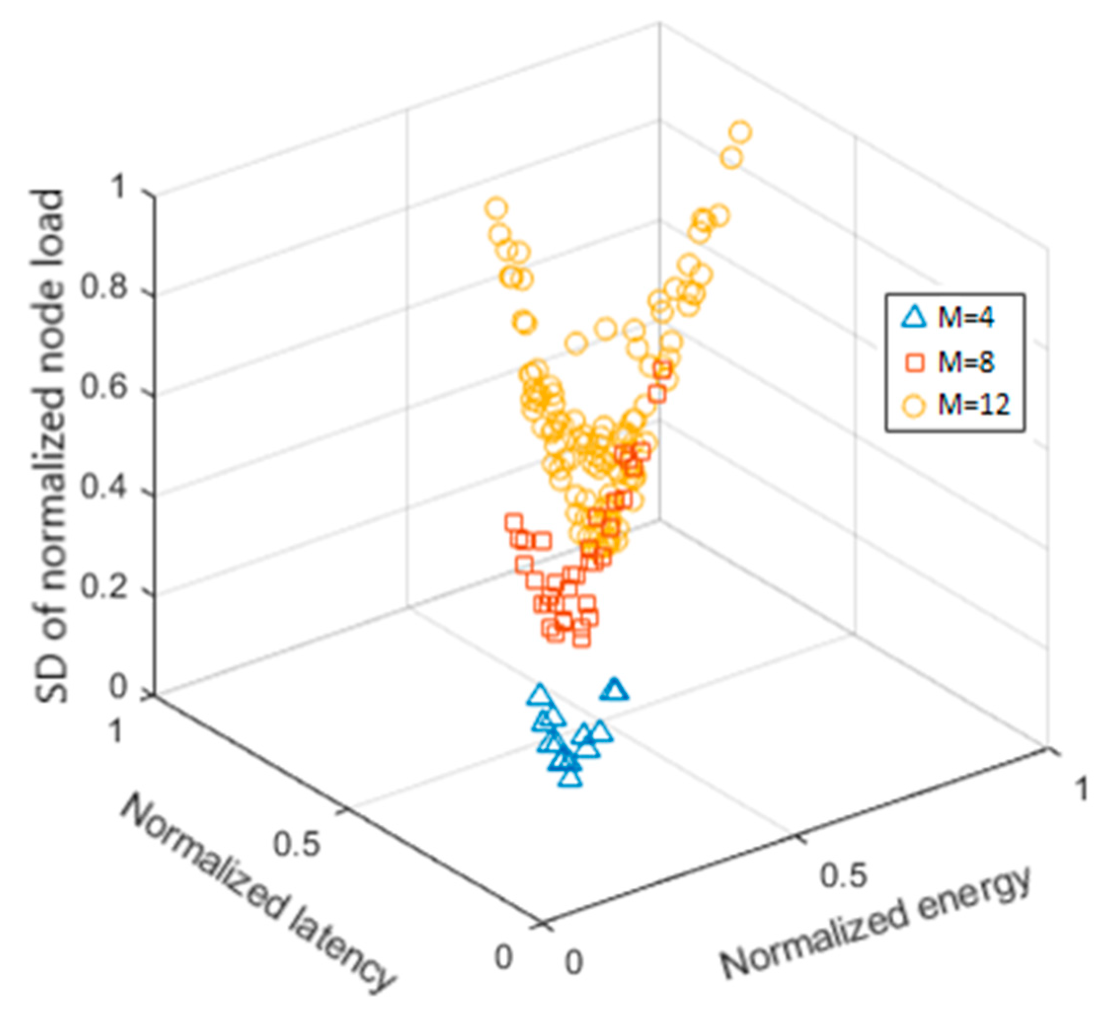
Figure 6 shows the pareto-fronts obtained under varying numbers of service tasks (), while maintaining the number of service nodes to its default value (). The number of pareto-points clearly increases with due to a greater population size and diversity of parent chromosomes arising from longer chromosome lengths. In addition, the pareto-fronts can be seen to shift towards higher energy and latency costs, which are confirmed by their higher mean and maximum values as shown in Table 3. This is because as increases, the demand for energy and time resources for each service node in a TNA increases, resulting in higher overall energy and latency costs of the TNAs.
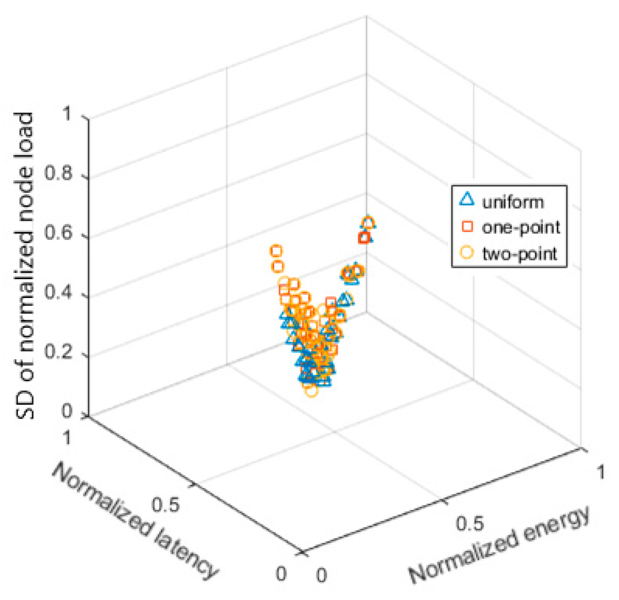
The impact of utilizing different crossover operators, single-point, two-point and uniform crossover, on the obtained pareto-fronts under a default number of service nodes and service tasks () is shown in Figure 7. It is found that while uniform crossover produced fewer pareto-points (55) than one-point (58) and two-point (64) crossovers, the solutions obtained are more optimal than those under one-point and two-point crossover. This can be observed from their closer proximity to the most optimal point, which is the point-of-origin (0,0,0). This observation is also statistically verified by a C-metric comparison of the solutions as shown in Table 4.
Figure 8 compares the obtained solutions by MOEA/D with those obtained by a competing technique, NSGA-II, under a default number of service nodes and service tasks (). The pareto-points of MOEA/D are found to have slightly lower values (closer to the point-of-origin), suggesting the solutions are more optimal than those from NSGA-II. This is confirmed by a C-metric comparison in Table 5 which shows that MOEA/D has a higher percentage of non-dominated solutions than NSGA-II.
7. Conclusions
In this paper, the concept of OF-RAN is proposed and the TNA problem in OF-RAN is formulated and solved as a tri-objective optimization problem using MOEA/D. The objectives are to minimize the energy and latency costs of the v-FAP, while maximizing fairness among its service nodes by minimizing their maximum load. The impacts of different number of service nodes, number of service tasks and crossover operator on the obtained solutions (TNAs) are investigated.
It is found that a higher number of service nodes in a v-FAP increases the number of solutions but decreases the energy cost, latency cost and the load standard deviation of the service nodes (suggesting better load balancing). On the other hand, a higher number of service tasks not only increases the number of solutions, but also increases the energy cost, latency cost and the load standard deviation of the service nodes. Among the considered crossover operators, the uniform crossover produces fewer but more optimal solutions than the one-point and two-point crossover. Finally, the solutions obtained from MOEA/D are found to be more optimal than those obtained from NSGA-II for our OF-RAN’s TNA problem.
As future work, we plan to investigate a formation protocol for v-FAPs and their roles in optimal functional splits between cloud and fog nodes for future radio access networks.
Author Contributions
Conceptualization, J.J. and B.-C.S.; Formal analysis, J.J.; Funding acquisition, B.-C.S.; Investigation, J.J.; Methodology, J.J.; Project administration, P.H.J.C.; Supervision, B.-C.S. and P.H.J.C.; Validation, J.J.; Writing—original draft, J.J.; Writing—review & editing, B.-C.S. and P.H.J.C. All authors have read and agreed to the published version of the manuscript.
Funding
This research has been supported by a doctoral fee scholarship from Auckland University of Technology and a stipend award from the Engineering Research Institute (ERI).
Conflicts of Interest
The authors declare no conflict of interest.
References
- D’Oro, S.; Marotta, M.A.; Both, C.B.; da Silva, L.; Palazzo, S. Power efficient resource allocation in C-RANs with SINR constraints and deadlines. IEEE Trans. Veh. Technol. 2019, 68, 6099–6113. [Google Scholar] [CrossRef] [Green Version]
- Tang, J.; Quek, T.Q.S.; Chang, T.-H.; Shim, B. Systematic resource allocation in cloud RAN with caching as a service under two timescales. IEEE Trans. Commun. 2019, 67, 7755–7770. [Google Scholar] [CrossRef]
- Puliafito, C.; Mingozzi, E.; Longo, F.; Puliafito, A.; Rana, O. Fog computing for the Internet of Things: A survey. ACM Trans. Internet Technol. 2019, 19, 18. [Google Scholar] [CrossRef]
- Tran, M.-Q.; Nguyen, D.T.; Le, V.A.; Nguyen, D.H.; Pham, T.V. Task placement on fog computing made efficient for IoT application provision. Wirel. Commun. Mob. Comput. 2019, 2019, 1–17. [Google Scholar] [CrossRef] [Green Version]
- Li, J.; Shen, X.; Chen, L.; Van, D.P.; Ou, J.; Wosinska, L.; Chen, J. Service Migration in Fog Computing Enabled Cellular Networks to Support Real-time Vehicular Communications. IEEE Access 2019, 7, 13074–13714. [Google Scholar] [CrossRef]
- Peng, M.; Yan, S.; Zhang, K.; Wang, C. Fog computing-based radio access networks: Issues and challenges. IEEE Netw. Mag. 2016, 30, 46–53. [Google Scholar] [CrossRef] [Green Version]
- Zhang, Q.; Gui, L.; Hou, F.; Chen, J.; Zhu, S. Dynamic task offloading and resource allocation in mobile edge computing in dense Cloud RAN. IEEE Internet Things J. 2020, 1-1. [Google Scholar] [CrossRef]
- Jijin, J.; Seet, B.-C. Opportunistic fog computing for 5G radio access networks: A position paper. In Smart Grid and Innovative Frontiers in Telecommunications (SmartGIFT). LNICST; Chong, P., Seet, B.-C., Chai, M., Rehman, S., Eds.; Springer: Cham, Switzerland, 2018; Volume 245, pp. 82–92. [Google Scholar]
- Lilien, L.; Gupta, A.; Kamal, Z.; Yang, Z. Opportunistic resource utilization networks—A new paradigm for specialized ad hoc networks. Comput. Elect. Eng. 2010, 36, 328–340. [Google Scholar] [CrossRef]
- Jijin, J.; Seet, B.-C.; Chong, P.H.J.; Jarrah, H. Service load balancing in fog-based 5G radio access networks. In Proceedings of the IEEE International Symposium on Personal, Indoor and Mobile Radio Communications (PIMRC), Montreal, QC, Canada, 8–13 October 2017. [Google Scholar]
- Konstantinidis, A.; Yang, K.; Zhang, Q.; Zeinalipour-Yazti, D. A multi-objective evolutionary algorithm for the deployment and power assignment problem in wireless sensor networks. Comput. Netw. 2010, 54, 960–976. [Google Scholar] [CrossRef]
- Liu, L.; Chang, Z.; Guo, X.; Mao, S.; Ristaniemi, T. Multiobjective optimization for computation offloading in fog computing. IEEE Internet Things J. 2018, 5, 283–294. [Google Scholar] [CrossRef]
- Cui, L.; Xu, C.; Yang, S.; Huang, J.Z.; Li, J.; Wang, X.; Ming, Z.; Lu, N. Joint optimization of energy consumption and latency in mobile edge computing for Internet of Things. IEEE Internet Things J. 2018, 6, 4791–4803. [Google Scholar] [CrossRef]
- Dinh, T.Q.; Tang, J.; La, Q.D.; Quek, T.Q.S. Offloading in mobile edge computing: Task allocation and computational frequency scaling. IEEE Trans. Commun. 2017, 65, 3571–3584. [Google Scholar]
- Li, X.; Zhou, D.; Pan, Q.; Tang, Y.; Huang, J. Weapon-target assignment problem by multi-objective evolutionary algorithm based on decomposition. Complexity 2018, 2018, 1–19. [Google Scholar]
- Peng, W.; Zhang, Q.; Li, H. Comparison between MOEA/D and NSGA-II on the multi-objective travelling salesman problem. In Multi-Objective Memetic Algorithms; Goh, C.-K., Ong, Y.-S., Tan, K.C., Eds.; Studies in Computational Intelligence; Springer: Berlin/Heidelberg, Germany, 2009; volume 171, pp. 309–324. [Google Scholar]
- Guerrero, C.; Lera, I.; Juiz, C. Evaluation and efficiency comparison of evolutionary algorithms for service placement optimization in fog architectures. Future Gener. Comput. Syst. 2019, 97, 131–144. [Google Scholar] [CrossRef]
- Cover, T.; Thomas, J. Elements of Information Theory, 2nd ed.; John Wiley and Sons: Hoboken, NJ, USA, 2006. [Google Scholar]
- Fei, Z.; Li, B.; Yang, S.; Xing, C.; Chen, H.; Hanzo, L. A survey of multi-objective optimization in wireless sensor networks: Metrics, algorithms, and open problems. IEEE Commun. Surv. Tutor. 2016, 19, 550–586. [Google Scholar] [CrossRef] [Green Version]
- Yang, X.S. Nature-Inspired Metaheuristic Algorithms; Luniver Press: Bristol, UK, 2010. [Google Scholar]
Figure 1.
OF-RAN architecture.

Figure 2.
The sequence of operations of a v-FAP.

Figure 3.
TNA example for N = 4 service nodes and M = 8 service tasks.

Figure 4.
Example of proposed chromosome encoding.

Figure 5.
Pareto-fronts obtained under varying numbers of service nodes () and a default number of service tasks ().
Figure 5.
Pareto-fronts obtained under varying numbers of service nodes () and a default number of service tasks ().

Figure 6.
Pareto-fronts obtained under varying numbers of service tasks () and a default number of service nodes ().
Figure 6.
Pareto-fronts obtained under varying numbers of service tasks () and a default number of service nodes ().

Figure 7.
Pareto-fronts obtained under different crossover operators and a default number of service nodes () and service tasks ().
Figure 7.
Pareto-fronts obtained under different crossover operators and a default number of service nodes () and service tasks ().

Figure 8.
Pareto-fronts obtained from MOEA/D and NSGA-II under the default number of service nodes () and service tasks ().
Figure 8.
Pareto-fronts obtained from MOEA/D and NSGA-II under the default number of service nodes () and service tasks ().


Table 1.
Simulation Settings.
| Parameter | Value |
|---|---|
| Number of service nodes () | 2, 4, 6 (default = 4) |
| Number of service tasks () | 4, 8,12 (default = 8) |
| Crossover Operator | One-point, two-point and uniform crossover |
| Population Size | |
| Neighborhood Size | 25 |
Table 2.
Mean and max. values of the objective costs under varying .
| Normalized Energy | Normalized Latency | S.D. of Normalized Node Load | ||||
|---|---|---|---|---|---|---|
| Mean | Max | Mean | Max | Mean | Max | |
| 2 | 0.8329 | 0.9377 | 0.8627 | 0.9746 | 0.3690 | 0.7322 |
| 4 | 0.8145 | 1.00 | 0.8348 | 1.000 | 0.3257 | 0.6167 |
| 6 | 0.7562 | 1.00 | 0.8059 | 0.9004 | 0.2244 | 0.5036 |
Table 3.
Mean and max. values of the objective costs under varying .
| Normalized Energy | Normalized Latency | S.D. of Normalized Node Load | ||||
|---|---|---|---|---|---|---|
| Mean | Max | Mean | Max | Mean | Max | |
| 4 | 0.2617 | 0.3339 | 0.2650 | 0.2790 | 0.1640 | 0.2539 |
| 8 | 0.5489 | 0.6778 | 0.6242 | 0.6684 | 0.2760 | 0.6087 |
| 12 | 0.7872 | 1.00 | 0.8713 | 0.9253 | 0.3550 | 0.8722 |
Table 4.
C-Metric of solutions obtained under one-point, two-point and uniform crossover.
| C-Metric | (%) |
|---|---|
| C (Uniform, One-point) | 100 |
| C (One-point, Uniform) | 81.81 |
| C (Uniform, Two-point) | 100 |
| C (Two-point, Uniform) | 81.81 |
| C (One-point, Two-point) | 98.44 |
| C (Two-point, One-point) | 98.27 |
Table 5.
C-Metric of solutions obtained under MOEA/D and NSGA-II.
| C-Metric | (%) |
|---|---|
| C (MOEA/D, NSGA-II) | 100 |
| C (NSGA-II, MOEA/D) | 96.30 |
© 2020 by the authors. Licensee MDPI, Basel, Switzerland. This article is an open access article distributed under the terms and conditions of the Creative Commons Attribution (CC BY) license (http://creativecommons.org/licenses/by/4.0/).
Share and Cite
MDPI and ACS Style
Jijin, J.; Seet, B.-C.; Chong, P.H.J. Multi-Objective Optimization of Task-to-Node Assignment in Opportunistic Fog RAN. Electronics 2020, 9, 474. https://doi.org/10.3390/electronics9030474
AMA Style
Jijin J, Seet B-C, Chong PHJ. Multi-Objective Optimization of Task-to-Node Assignment in Opportunistic Fog RAN. Electronics. 2020; 9(3):474. https://doi.org/10.3390/electronics9030474
Chicago/Turabian StyleJijin, Jofina, Boon-Chong Seet, and Peter Han Joo Chong. 2020. "Multi-Objective Optimization of Task-to-Node Assignment in Opportunistic Fog RAN" Electronics 9, no. 3: 474. https://doi.org/10.3390/electronics9030474
Note that from the first issue of 2016, this journal uses article numbers instead of page numbers. See further details here.