Gravitational Lensing in Presence of Plasma: Strong Lens Systems, Black Hole Lensing and Shadow

1
Space Research Institute of Russian Academy of Sciences, Profsoyuznaya 84/32, Moscow 117997, Russia
2
National Research Nuclear University MEPhI (Moscow Engineering Physics Institute), Kashirskoe Shosse 31, Moscow 115409, Russia
*
Author to whom correspondence should be addressed.
Universe 2017, 3(3), 57; https://doi.org/10.3390/universe3030057
Submission received: 26 April 2017
/
Revised: 5 July 2017
/
Accepted: 13 July 2017
/
Published: 17 July 2017
(This article belongs to the Special Issue Gravitational Lensing and Astrometry)
Abstract
:In this article, we present an overview of the new developments in problems of the plasma influence on the effects of gravitational lensing, complemented by pieces of new material and relevant discussions. Deflection of light in the presence of gravity and plasma is determined by a complex combination of various physical phenomena: gravity, dispersion, refraction. In particular, the gravitational deflection itself, in a homogeneous plasma without refraction, differs from the vacuum one and depends on the frequency of the photon. In an inhomogeneous plasma, chromatic refraction also takes place. We describe chromatic effects in strong lens systems including a shift of angular position of image and a change in magnification. We also investigate high-order images that arise when lensing on a black hole surrounded by homogeneous plasma. The recent results of analytical studies of the effect of plasma on the shadow of the Schwarzschild and Kerr black holes are presented.
1. Introduction
1.1. Refraction
Gravitational lensing theory describes a wide range of phenomena connected with deflection of light by gravity. Gravitational lensing includes many effects: a change of apparent angular position of the source, multiple imaging, magnification (change of the flux), distortion (change of the shape), time delay. Currently gravitational lensing is a powerful astrophysical tool for investigations of distant objects, a distribution of dark matter and large scale structure, the cosmic microwave background, discovery of planet and checking of the General Relativity, see some reviews, classical and interesting recent works [1,2,3,4,5,6,7,8,9,10,11,12,13,14,15,16,17,18,19,20,21,22,23]. In present paper we discuss how presence of plasma may influence various effects of gravitational lensing.
In outer space, rays of light travel through plasma. In plasma, photons undergo various effects, such as absorption, scattering and refraction. For gravitational lensing, which is usually used in the approximation of geometric optics, the main interest is a change of the angle of deflection of a light ray. Due to dispersion properties of plasma, we may expect also that chromatic effects will arise.
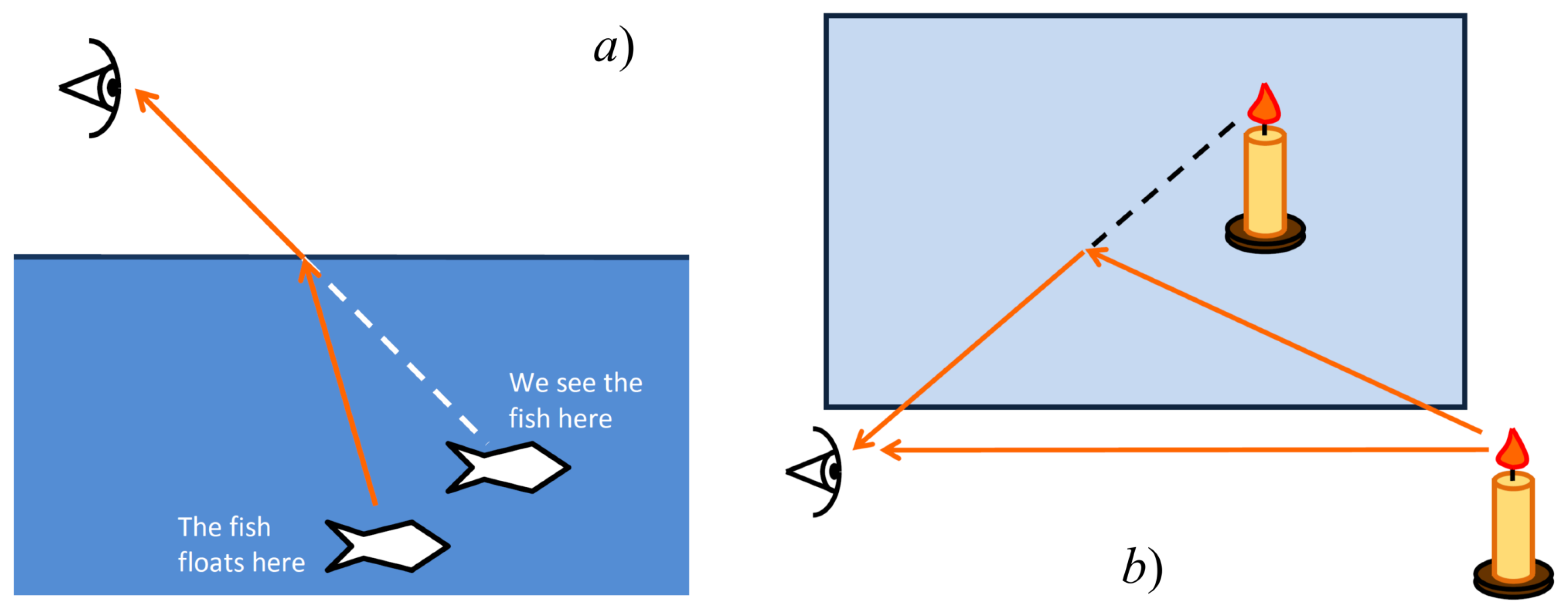
It is widely known that light rays in a transparent, inhomogeneous medium propagate along curve trajectories [24,25]. This phenomenon is called refraction and is well known from everyday life. For example, due to the refractive effect, the image when viewed through the optical lens differs from the true one, a spoon in the glass of water seems to be broken, and a depth of the pond seems to be less than in reality. The bending of the light rays due to refraction is not related to relativity or gravity and occurs only if the medium is optically non-homogeneous (Figure 1).
The simplest way to add plasma to the problem of the gravitational lensing is to consider cases, when both deflection angles, due to gravity and due to refraction in the plasma, are small, and these angles can be calculated separately from each other. To calculate the gravitational angle of deflection, it is sufficient to use the linearized theory of gravitation, i.e., to use the approximate Einstein formula for the deflection angle. To calculate the refraction, we can assume that the refractive index of the plasma differs only slightly from unity (vacuum).
In this approximation, the joint action of gravitation and refraction was investigated from the 1960’s, with reference to the propagation of radio signals in the solar corona. The rays of light, passing close to the Sun, are deflected both by solar gravity and by plasma in the solar corona. The corresponding angles of deflection were calculated by Muhleman et al. [26,27], see also [28]. The deflection due to refraction in this case is chromatic, i.e., it depends on the frequency of the photon. The same approximation was used by Bliokh and Minakov [29] who first considered this problem in the context of gravitational lensing. They investigated a point gravitational lens surrounded by an inhomogeneous plasma with a power law density distribution.
1.2. General Theory of the Geometrical Optics in a Medium, in Presence of Gravity
For a more detailed study of the effects of gravitational lensing in a plasma, a more rigorous approach is required. First of all, black holes and other compact objects can also be surrounded by a plasma. To describe the rays passing near such a compact object, the linearized theory of gravity is insufficient. The second interesting question is whether the gravitational deflection itself is changed in the presence of a medium around a gravitating body, in comparison with a vacuum case. We should also not forget that in addition to a point lens, there are many complex lens models. It turns out that more rigorous treatment of the subject reveals more complicated behaviour and new chromatic effects.
In order to deal with the issues mentioned above, it is necessary to use a theory that allows simultaneously to describe both the curvature of the spacetime (gravity) and the presence of the medium. The first self-consistent approach to the light propagation in the gravitational field in presence of a medium was developed in the classical book by Synge [30], for subsequent discussions see [31,32,33], see also work of Kulsrud and Loeb [34]. The comprehensive review of the general relativistic ray optics in media is presented in the monograph by Perlick [35]. In particular, general formulas for the light deflection angle in the Schwarzschild and Kerr metrics (in the equatorial plane) in the presence of a spherically distributed plasma have been obtained in the integral form [35], see also [36,37]. For propagation of electromagnetic waves in magnetized plasma see series of papers of Breuer and Ehlers [38,39,40], and of Broderick and Blandford [41,42,43].
Detailed investigation of physical properties and different situations of gravitational lensing in plasma have been started in series of papers of Bisnovatyi-Kogan and Tsupko, see References [36,44,45], for review see Reference [37]. We wrote down the Synge’s equations for the Schwarzschild metric and investigated various situations and models of lensing. In particular, it has been shown that gravitational deflection itself is different from vacuum case, and is chromatic in plasma, even in the case when plasma is homogeneous and refractive deflection is absent [44,45]. In non-homogeneous plasma both, chromatic gravitational deflection and chromatic refractive deflection are present. So, the presence of plasma always makes gravitational lensing chromatic. In particular, it leads to a difference in the angular positions of the same image at different wavelengths. Gravitational lensing in plasma was also investigated at large deflection angles, when the light rays pass very close to the black hole and so called high-order (relativistic) images are formed [36]. Subsequently, investigations of lensing in plasma have been continued by many authors [46,47,48,49,50,51,52,53,54,55], mostly with using the same formalism, see details below.
1.3. Strong Lens Systems
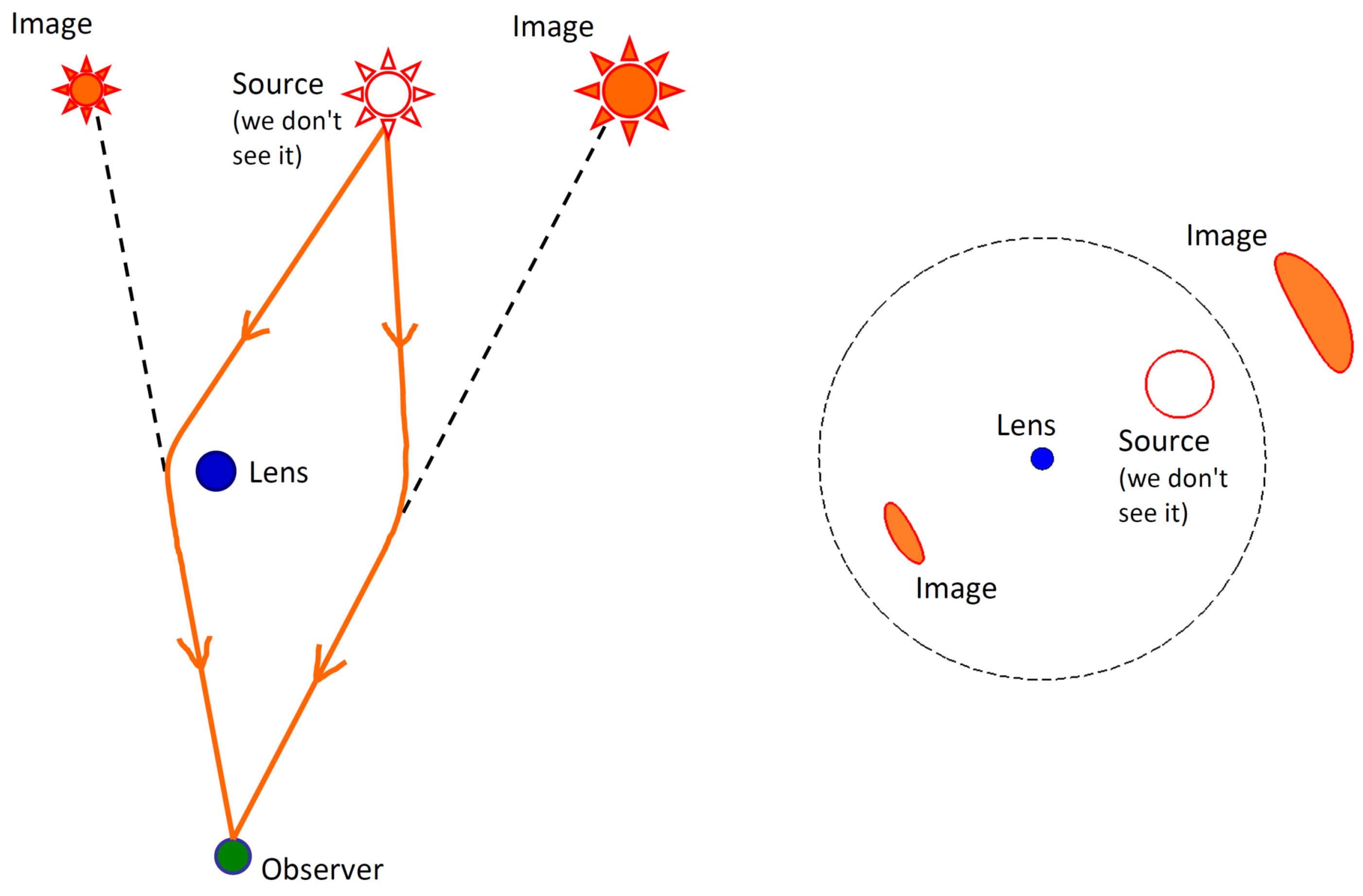
One of the most beautiful effects of gravitational lensing is appearance of multiple images of the same source. This effect is easily demonstrated in the simplest case of lensing by point mass (Figure 2). In the case of a strong lens system the distribution of matter in lens is more complicated than just point mass, with essential deviations from spherical, or any types of symmetry. Nevertheless, the weak deflection approximation still can be used, meaning that each small portion of matter deflects light in accordance with the approximate Einstein formula.
At the present level of development of observations, chromatic effects of lensing in a plasma might be observed only in a strong lens system1. This means that the lens is a galaxy or a cluster of galaxies, and there are several images of the same distant source, for example, quasar. Due to the presence of plasma, when observing images in different wavelengths, we expect to see different angular positions. By measuring the difference in angular positions, we can obtain information about the distribution of the plasma in the lens. Calculation of the deflection angles for different mass and plasma distributions in the lens is done in the work of Bisnovatyi-Kogan and Tsupko [45]. For the case of a homogeneous plasma, positions and magnifications of images were calculated analytically. Modelling of plasma effects in strong lens systems, similar to Einstein Cross, was performed in the paper of Er and Mao [47]. Authors have found that effects of plasma are possible to be detected in the low frequency radio observations.
1.4. Black Hole Lensing
Unlike stars and galaxies, in the case of lensing by a black hole, the impact parameter of a photon can be of the order of the Schwarzschild radius. In this case, the action of gravity is strong, and the deflection angle of the photon is not small. Linearized theory of gravity is not sufficient, and the deflection angle can not be calculated by Einstein’s formula. In a vacuum, it is necessary to use the exact equations of photon motion, which lead to an integral expression for the deflection angle. In the case of plasma, it is necessary to obtain exact equations of the photon motion, using either the Synge’s theory [30], or the Perlick’s method [35], which again leads to an expression for the deflection angle in the integral form.
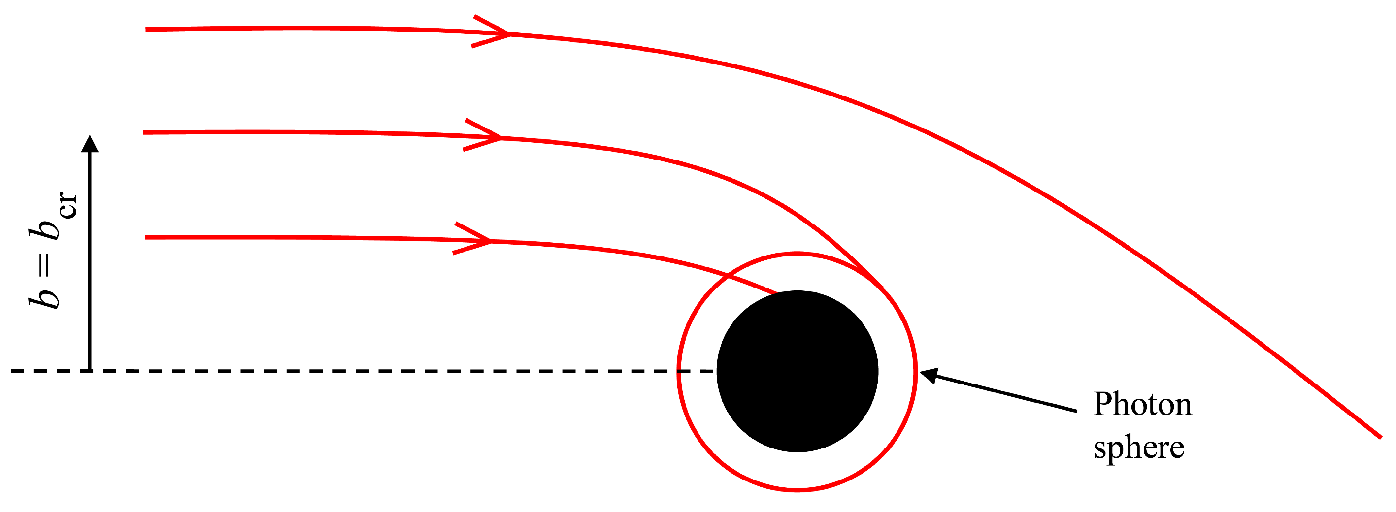
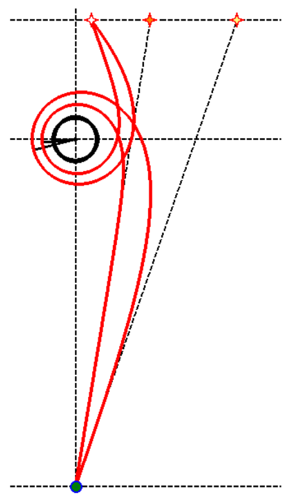
There is a critical value of the impact parameter, which divides the incident photons into two types (Figure 3). Photons, in which the impact parameter is less than critical, are absorbed by a black hole. The photons with the impact parameter greater than the critical, after approaching the black hole, again fly off to infinity. In this case, if the impact parameter is close to the critical one, the photons can make one or several revolutions around a black hole before flying off to infinity. Such photons give rise to an infinite sequence of images on both sides of the black hole, these are so-called high-order images or relativistic images. Thus, when lensing on a black hole, there are, first, two ’ordinary’ images of the source (formed by the photons with ), and secondly, two infinite sequences of high-order images (formed by the photons with ), see Figure 4. Note that in case of the perfect alignment of the source, the black hole and the observer, two ordinary images merge in one image—the Einstein ring, and there is the infinite sequence of relativistic rings, see Figure 5.
The calculation of relativistic images can be made using the exact deflection angle in the lens equation. Exact deflection angle of photon moving in vacuum in the Schwarzschild metric was calculated in paper of Darwin [56], it has a form of the integral, and can be expressed via elliptic integrals [56,57]. By using the exact expression for the deflection angle, the properties of relativistic images had been calculated in paper of Virbhadra and Ellis [58], see also paper [59]. The exact gravitational lens equation in spherically symmetric and static space-times was considered by Perlick [60].
The investigation of relativistic images is simplified if we use the so-called strong deflection approximation which is opposite to weak deflection approximation. This approximation means that the deflection angle is much greater than unity. When the impact parameter approaches the critical value, the deflection angle logarithmically diverges, formally tending to infinity. The logarithmically divergent expression for the photon deflection angle in vacuum in the strong deflection limit was obtained by Darwin for the Schwarzschild metric [56], see also [61].
Strong deflection limit provides very high accuracy for photons that have made one or more turns, so it is convenient to use it to calculate the properties of relativistic images. Analytical calculation of the positions and magnifications of relativistic images was made in the article of the Bozza et al. [61]. Later Bozza [62] has derived analytical expression for the deflection angle in general form, for generic spherically symmetric space-time. In particular, it was shown that for any spherically symmetric space-time the deflection angle diverges logarithmically when the impact parameter approaches its critical value. Relativistic rings (Figure 5) were investigated in details in work [57].
The subject of gravitational lensing beyond weak deflection approximation becomes very popular, because in the strong field regime it is possible to differ and compare different theories of gravity, see, for example, Refs. [3,57,63,64,65,66,67,68,69,70,71,72,73,74,75,76,77,78]. Nevertheless, there are no big chances so far to observe the high-order images.
Similarly to photons, a massive particle incident from infinity to the gravitating center, for certain values of the parameters, can also make several revolutions around the central body and fly away to infinity. Radius of unstable circular orbits was investigated in works of Zakharov [79,80]. Recently, analytical expressions for deflection angles of massive particles in the Schwarzschild metric in strong deflection limit were derived for the first time by Tsupko [81]. The same problem have been considered later in paper of Liu, Yang and Jia [82], in the context of gravitational lensing of massive particles.
Investigation of gravitational lensing in plasma beyond weak deflection approximation is made in Ref. [36]. The angle of deflection of a photon in the Schwarzschild field and in a homogeneous plasma was derived. The positions and magnifications of relativistic images were analytically calculated. It is shown that the presence of the uniform plasma increases the angular size of relativistic rings or the angular separation of point images from the gravitating center. The presence of the uniform plasma increases also a magnification of relativistic images [36]. This consideration have been recently extended to Kerr spacetime by Liu, Ding and Jing [54].
Complicated behaviour of light rays near compact objects was demonstrated in series of papers of Rogers [49,50,51,52]. Trajectories of light rays are investigated in spherically symmetric metric with different power-law plasma distribution. As a relevant physical example the propagation of radiation emitted from a compact object sheathed in a dense plasma had been examined [49]. The plasma distribution significantly affects the appearance of the compact object for a distant observer, by changing the portion of the surface that is visible as a function of frequency. Rogers also investigated stable circular orbits of light rays in non-homogeneous plasma distribution [52]. Bound orbits of light rays in the homogeneous plasma case were discussed in [34,36].
1.5. Lensing by Kerr Black Hole in Presence of Plasma
The deflection angle for a light ray moving near a Kerr black hole surrounded by a plasma was first derived by Perlick in the form of the integral [35]. The derivation is made for the equatorial plane of a black hole, and spherically symmetric distribution of the plasma. For the non-equatorial motion of a photon, the deflection angle is derived in the article by Morozova, Ahmedov and Tursunov [46], in the weak deflection approximation. These authors generalize the method used in the paper [45] for the Schwarzschild metric to the case of a homogeneous plasma and a weakly rotating black hole. As mentioned, relativistic images in lensing on a Kerr black hole surrounded by a plasma are investigated in the article [54]. The equations of motion for an arbitrary distance of a photon from a black hole, an arbitrary ray inclination, and an arbitrary Kerr parameter are obtained in the article of Perlick and Tsupko [55]. The article shows that the separation of variables in the Hamilton-Jacobi equation, the existence of the Carter constant generalized for the plasma, and complete integrability of the equations of motion are possible only for specific plasma distributions around the Kerr black hole.
1.6. Black Hole Shadow
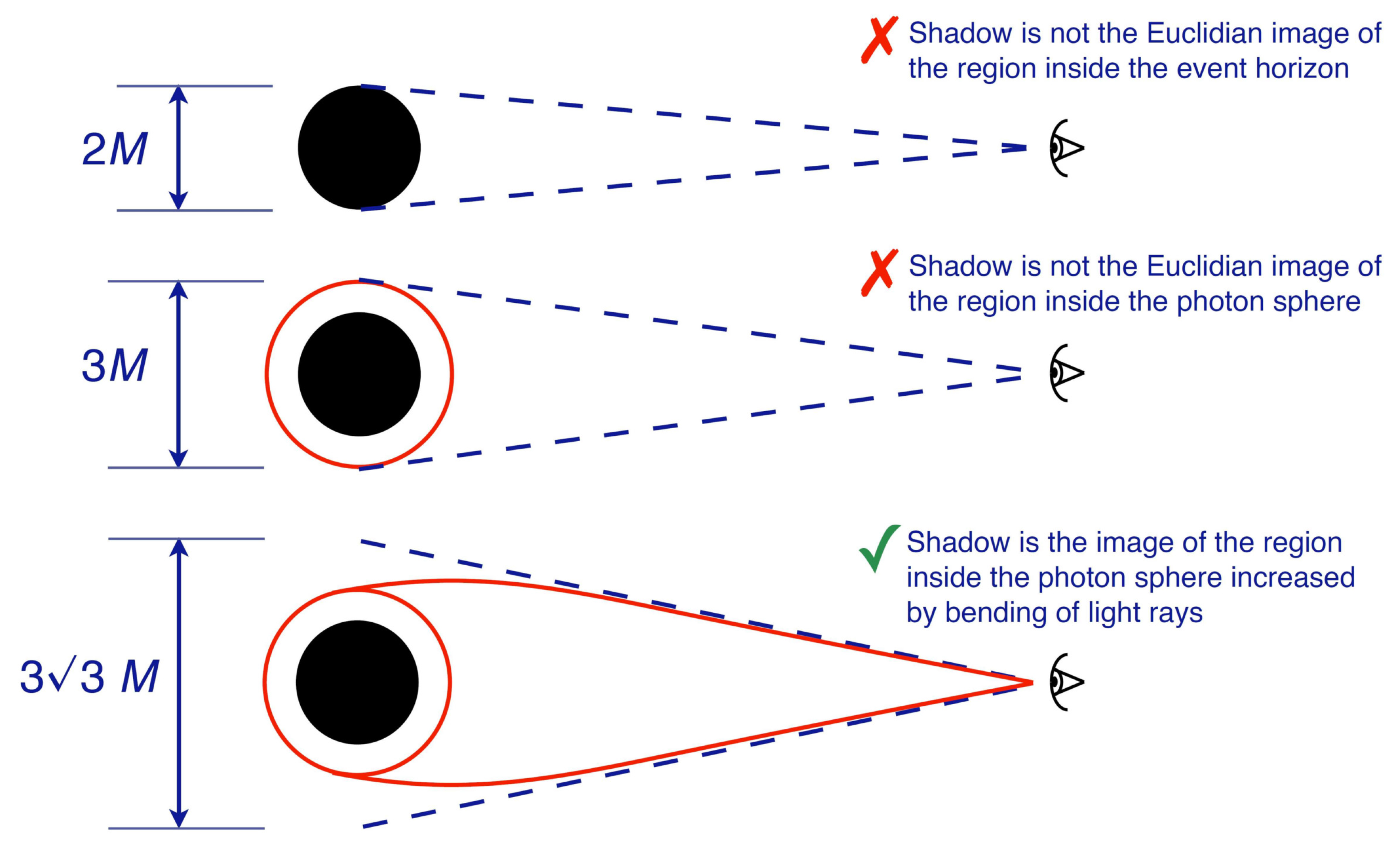
In close connection with lensing by a black hole is a topic of a black hole shadow. It is expected that a distant observer should ’observe’ the black hole as a dark spot (on the background of bright sources) in the sky which is known as the ’shadow’.
This topic is now becoming very popular due to the appearance of projects to observe the shadow of a supermassive black hole in the center of our Galaxy. Observing the shadow of black hole is both very challenging and very difficult task due to many effects involved. For the black hole at the center of our Galaxy, the size of the shadow is about 53 as (which approximately corresponds to the size of a grapefruit on the Moon if observed from the Earth). At present, two projects are under way to observe this shadow which would give an important information about the properties of the compact object at the center of our Galaxy. These projects, which are going to use (sub)millimeter VLBI observations with radio telescopes distributed over the Earth, are called as the Event Horizon Telescope (http://eventhorizontelescope.org) and the Black Hole Cam (http://blackholecam.org).
For a non-rotating black hole, the shadow is a circular disk at the sky. For a Schwarzschild black hole the angular diameter of the shadow was calculated, as a function of the mass of the black hole, and of the coordinate distance from the black hole to the observer by Synge [83]. For the Kerr black hole, the shadow becomes oblate and deformed. The shape of the shadow of a Kerr black hole, for an observer at infinity, was calculated by Bardeen [84]. In the papers [85,86], the size and the shape of the shadow were calculated for the whole class of Plebański-Demiański spacetimes (which includes the Kerr black hole as a special case). Calculations are performed for the observer at an arbitrary position outside of the horizon of the black hole. Numerous analytical investigations and numerical simulations of the shadow are presented in literature (for example, see [79,80,87,88,89,90,91,92,93,94,95,96,97,98,99,100,101,102,103,104,105,106,107,108,109,110,111]).
Influence of a matter on the shadow is usually investigated by numerical calculation. In particular, Falcke, Melia and Agol [90] have numerically simulated the visual appearance of the black hole at the center of our Galaxy, assuming that it is a Kerr black hole, with scattering and the presence of emission regions between the observer and the black hole taken into account (at 0.6 and 1.3 mm wavelengths). Sophisticated ray tracing programs have been written for producing realistic images of a black hole surrounded by an accretion disk, e.g., for the movie Interstellar, see details in [101].
The first attempt of analytical investigation of plasma influence on the shadow size, in the frame of geometrical optics, taking into account effects of general relativity and plasma presence, was performed in paper [48]. The Synge’s formula was generalized to the case of a spherically symmetric and static plasma distribution on a spherically symmetric and static spacetime. As particular examples, the results for a Schwarzschild black hole and an Ellis wormhole have worked out.
Recently, the shadow of a Kerr black hole under the influence of a plasma have been investigated analytically [55]. An analytical formula for the boundary curve of the shadow on the sky for an arbitrarily situated observer has been derived.
1.7. Additional Notes about Propagation of Light Rays in Medium
Plasma has unique dispersive properties, that leads to interesting analogy between motion of photon in homogeneous plasma and massive particle in vacuum. In the paper of Kulsrud and Loeb [34] (see also papers of Broderick and Blandford [41,42,43]) it was shown that in the homogeneous plasma the photon wave packet moves like a particle with a velocity equal to the group velocity of the wave packet, with a mass equal to the plasma frequency (multiplied by ℏ), and with an energy equal to the photon energy2. Therefore trajectories of light rays moving in homogeneous plasma can be investigated with using results for massive particles moving in vacuum. For example, chromatic deflection of light in homogeneous plasma can be explained by chromatic group velocity of photons (photons of different frequencies have different speeds, and thus their geodesics are bent by gravity in different ways), see also Section 2.2. Note that this analogy is applicable only for homogeneous plasma, and does not work for medium with arbitrary refraction index, see below.
As for massive particle in vacuum, bound elliptic orbits of the photons in homogeneous plasma are also possible. Gravitational binding of the photon in homogeneous plasma was discussed in the paper of Kulsrud and Loeb [34] and in Section 6 of paper of Tsupko and Bisnovatyi-Kogan [36]. For non-homogeneous plasma distributions, stable orbits of light rays were investigated for the first time by Rogers [52]. Variety of orbits including circular and periodic orbits are revealed, for beautiful illustrations see [52].
The main properties of the gravitational deflection in different media can be formulated as [44]:
- (i)
- In vacuum the gravitational deflection is achromatic.
- (ii)
- If a medium is homogeneous and not dispersive (the refractive index n is just a constant, it does not depend either on the space coordinates or on the photon frequency), the gravitational deflection angle is the same as in vacuum. Nevertheless, the group speed is smaller than light speed in vacuum.
- (iii)
- If the medium is homogeneous but dispersive (the refractive index does not depend on the space coordinates but depends on the photon frequency), the gravitational deflection angle is different from the vacuum case and depends on the photon frequency. For example: plasma.
- (iv)
- If medium is non-homogeneous (the refractive index depends on the space coordinates), we will have also the refractive deflection. If medium is non-homogeneous and dispersive, the refractive deflection depends on the photon frequency.
The present paper is organized as follows. In next section we consider a calculation of the photon deflection angle in presence of both gravity and plasma. In Section 3 we discuss gravitational lensing in plasma in case of strong lens systems with several observed images. In Section 4 we consider black hole lensing, when the deflection angles can be large and relativistic images can arise. In Section 5 and Section 6 the influence of plasma on the black hole shadow is described.
2. Deflection Angle in Presence of Plasma in Schwarzschild Metric
2.1. Exact Expression for the Deflection Angle
Let us consider a spherically symmetric and static metric
where metric coefficients , and are positive. Throughout this paper we use , except Section 6.
We assume that the spacetime is filled with a static non-magnetized cold3 inhomogeneous plasma whose electron plasma frequency is a function of the radius coordinate only,
The refraction index n of this plasma is
Here is the electron plasma frequency, is the electron concentration in plasma, e is the charge of the electron, m is the electron mass4. The frequency measured by a static observer is a function of r, according to the gravitational redshift formula,
Here is the frequency at infinity.
Now let us restrict ourselves by the consideration of the Schwarzschild metric:
In the case of a plasma with the refractive index (3), the Hamiltonian with the photon momentum 4-vector can be written in the form [35,44,45]
The system of equations of motion for the space components , are:
For explicit form of these equations in Cartesian coordinate system see References [44,45], in spherical coordinate system see References [36,37]. The deflection angle of the photon moving from infinity to the central object and then to infinity is
Here we use notation
This expression for was derived for the first time in [35], and rederived in [36] by Synge’s approach. At given M and , the deflection angle is determined by the closest approach distance R and the photon frequency at infinity . This formula allows us to calculate the deflection angle of the photon moving in the Schwarzschild metric in presence of a spherically symmetric distribution of plasma. The expression of (8) via elliptic integrals for the case of homogeneous plasma can be found in [36,37].
Exact expression for deflection angle in presence of Schwarzschild gravity and plasma (8) is a manifestation of simultaneous and mutual action of different physical effects: gravity, refraction, dispersion. This angle (8) can not be calculated analytically in a general case. For analysis and applications of this result it is convenient to consider some particular cases with appropriate approximations. Considering the case of small total deflection angle , we have advantages to see clearly which physical reasons give contributions to different parts of the total deflection, see References [37,44,45].
2.2. Homogeneous Plasma, Weak Deflection
In the case of a homogeneous plasma with const the refractive index does not depend on the space coordinates explicitly, so the refractive action is absent. Therefore, in homogeneous case, we can consider the angle as the gravitational deflection in a given medium (plasma). Despite the absence of deflection due to refraction, this deflection differs from vacuum gravitational deflection.
In the homogeneous plasma, the total deflection angle represents only the action of the gravitation. In more complicated situation, when plasma is non-homogeneous, both effects presents: difference of gravitational deflection from vacuum case due to presence of medium, and refractive deflection due to medium inhomogeneity. In weak deflection approximation it is possible to study them separately from each other.
Let us consider a situation when the closest approach distance is much larger than the Schwarzschild radius, (). It means also that (during the motion the r-coordinate changes from R to infinity), , and the resulting deflection angle is small, . Expanding the exact Formula (8) with const, we obtain the deflection angle in the form (see Appendix A of [37]):
For gravitational lensing the dependence of angles on impact parameter b is needed. In approximation the difference between R and b is negligible, so we can just substitute into (10), obtaining
The deflection angle (11) can be also derived in a simpler way, see [44,45]. To do this, the Synge’s equations have been written in Cartesian coordinates. We have considered the photon with unperturbed trajectory in a homogeneous plasma as a straight line parallel to z-axis with an impact parameter b, and have found the deflection in the approximation of small perturbations, by the integration along the straight trajectory.
Formula (11) is valid only for , because the waves with do not propagate in the plasma. At approaching , the gravitational deflection in plasma can be much larger than in the vacuum, (condition should be satisfied too). Formula (11) does not imply that . If it is additionally supposed, we can rewrite the deflection (11) as:
Here we denote the vacuum gravitational deflection as and additional correction to the gravitational deflection connected with the plasma presence as .
The presence of plasma increases the gravitational deflection angle. In homogeneous plasma the photons of smaller frequency, or larger wavelength, are deflected by a larger angle by the gravitating center. The effect of difference in the gravitational deflection angles is significant for longer wavelengths, when is approaching . That is possible only for the radio waves. Therefore, the gravitational lens in plasma acts as a radiospectrometer [44]. We should use Formula (11) when we consider gravitational lensing of radiowaves by point or spherical body in presence of homogeneous plasma. This effect has a general relativistic nature, in combination with the dispersive properties of plasma. We should also emphasize that the plasma is considered here like the medium with a given index of refraction, and this formula does not take into account gravitation of particles of plasma.
In the case of axisymmetric mass distribution the deflection with the impact parameter b is equal to the Einstein angle for the mass , where is the projected mass enclosed by the circle of the radius b. In another words it is mass inside the cylinder with the radius b. So, for this case, we should write [1,2,12,29]:
Formula (11) can be recovered with using the analogy between the motion of photon in the homogeneous plasma and massive particle in vacuum, described in the Introduction, in Section 1.7. Test massive particle passing with the velocity v near a spherical body with the mass M, with the impact parameter , is deflected by the angle defined as [28,112]:
Using group velocity of wave packet in the homogeneous plasma , we obtain the Formula (11).
2.3. Non-Homogeneous Plasma, Weak Deflection
In the case of a plasma non-homogeneity there is also the refractive deflection, . Our approach for gravitational lensing in plasma developed in [44,45] allows to consider two effects simultaneously: the gravitational deflection in plasma which is different from the Einstein angle, and the refraction connected with the plasma inhomogeneity which does not depend on the gravity. In the paper [45] we have derived formulae for the deflection angle by a spherical body, or spherically distributed gravitating matter, in presence of a homogeneous and non-homogeneous plasma, with taking into account the gravitation deflection together with the refractive deflection.
In applications the usual vacuum gravitational deflection gives the major contribution to the total deflection , and all effects connected with plasma presence are significally smaller: and .
Additional correction to the gravitational deflection caused by plasma is in most cases smaller than correction due to refraction (note that both corrections have the same frequency dependence, they are proportional to ). In these cases the total deflection angle (in a weak deflection approximation) can be written as a sum of vacuum gravitational deflection and refractive deflection . In this approximation is neglected, and the gravitational deflection is taken as equal to vacuum gravitational deflection [29].
Expanding the exact integral Formula (8) with and , we obtain an approximate formula for the case of a weak deflection in non-homogeneous plasma (see Appendix B in [37]):
For gravitational lensing the dependence of angles on the impact parameter b is needed. In papers [44,45] we have derive using Cartesian coordinates. We have considered the photon with the unperturbed trajectory as a straight line parallel to z-axis, with the impact parameter . In this case we have, at given b:
Here and , so the expression under the integral sign is a function of b and z. To calculate the deflection angle, we perform partial differentiation with respect to b at constant z and then, after integration along z at constant b, obtain deflection angle as a function of b. In Appendix B of [37] we have also shown how to transform in the form (15) into form (16).
The presence of homogeneous or non-homogeneous plasma increases the gravitational deflection of photons. A vacuum gravitational deflection is usually considered as positive () therefore the additional correction to gravitational deflection due to plasma presence is also positive (). The refractive deflection can be both positive or negative, depending on the density profile. Usually the density of plasma in different models decreases with radius (), therefore the refractive deflection is usually opposite to the gravitational deflection: the correction due to refractive deflection is negative (), see [45].
For example, in the case of inhomogeneous plasma with a power-law concentration
the refractive deflection is
3. Effects of Plasma in Strong Lens System
3.1. Shift of Angular Position of Image
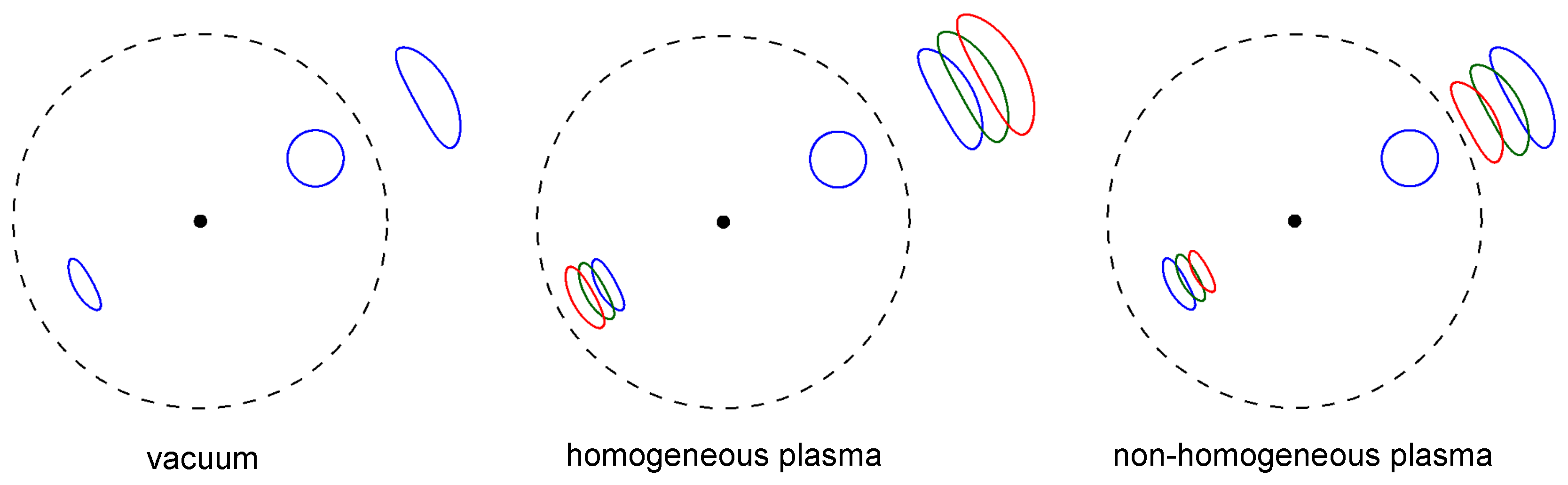
Presence of plasma always makes gravitational lensing chromatic. In the case of a homogeneous plasma the chromatic effects arise due to difference of gravitational deflection itself from vacuum case. In non-homogeneous plasma case the chromatic refractive deflection takes place in addition. The observational effect of the frequency dependence may be explained on the example of the Schwarzschild point-mass lens [44,45]. Instead of two concentrated images with complicated spectra, we will have two expanded images, formed by the photons with different frequencies, which are deflected by different angles (Figure 6). To see the difference in angular position of images, we should compare radio and optical observations of images. For optical frequencies the effect of plasma presence is negligible, and positions of images in this case can be calculated with the vacuum formulae.
In the case of strong lens system, it is sufficient to use the weak deflection approximation. For homogeneous plasma and point mass lens the Formula (11) can be used. If it is additionally assumed that plasma frequency is much smaller than the photon frequency, the Formula (12) can be used. For non-homogeneous plasma and point mass lens the Formula (16) is sufficient. For power-behaved distribution of plasma the refractive deflection is calculated by (18). If gravitating mass is distributed, for calculation of the gravitational deflection see (13).
For observational prediction of plasma effects described above we refer to work of Er and Mao [47] who have performed the numerical modelling of plasma effects in strong lens system similar to Einstein Cross. Authors have used realistic distribution of plasma for spiral and elliptical galaxies, and have investigated numerically the influence of plasma presence on position of the images. The total deflection angle was calculated as a sum of vacuum gravitational deflection and refractive plasma deflection, with using Formulas from [44,45]. For calculation of gravitational deflection the lens at redshift 0.5, and the source at redshift 2.0 were considered, with a size of the vacuum Einstein ring equal to 0.4 arcsec.
For refractive plasma deflection authors have considered two plasma models. The first one is for a spiral lensing galaxy with the plasma concentration
where r is the radial distance from the center of the galaxy, and constants are cm, and kpc. The second plasma model is used as appropriate for elliptical galaxies:
with cm and kpc. These values of correspond to the plasma frequency sec and sec. Authors have found that for the radio frequency 375 MHz of the photon the difference in image positions due to plasma presence can be a few tenth milliarcsecs (for the first model), what is possible to detect for the low frequency radio observations [47]. Similar changes will happen for the magnification of the lensed images, but there are also some other factors which can change the magnification more significantly, such as the substructures in the lens galaxy or cluster.
To conclude this Section, let us formulate the following way of observation of plasma effects in strong lens systems:
- (i)
- Compare observations of strong lens system with multiple images in optical and radio band, or compare observations in two radio bands;
- (ii)
- Shift of the angular position of every image can be observed.
As a result, we could make estimations of plasma properties in the vicinity of lens. Note that the emission regions of the source in different bands may not coincide. Speaking about quasars we can expect that the centers of emission regions will be coincide due to symmetry of accretion disc, and only jets separated from the central black hole can have angular position different from the main source. Nevertheless, even in this case plasma effects can be extracted, assuming spherically symmetric distribution of plasma. Its presence leads to a shift of every image mainly in the plane passing through observer, lens and this image, whereas the change of the source position leads to more complicated changes of image positions.
3.2. Effect on Flux Ratio in Different Wavelengths
Gravitational lensing also leads to magnification of the source. This means that the flux of the image is larger or smaller than the flux of the unlensed source, and the ratio of these fluxes is referred as magnification. Magnification is determined by the ratio of solid angles of lensed image and unlensed source, different images have different magnifications. The magnification properties are determined by the deflection law, and the magnification of every image can be calculated for given lens system.
In observations we don’t know the intrinsic flux of the source and its spectrum, therefore we can not observe the magnification of every image directly. What we can do is to observe and compare the fluxes of images; ratio of fluxes of different images equals to the ratio of calculated magnifications of these images.
For study of plasma effects we need to investigate the flux ratio in different bands. In vacuum the gravitational deflection is achromatic. Therefore the ratios of the fluxes of images in different bands should be the same, if we consider lensing in vacuum.
For example, let us consider two observed images, 1 and 2, in strong lens system. Fluxes F of images in optical and radio frequences will have the same ratios:
This situation is changed if we assume that the lens is surrounded by plasma. In the case of lensing of radio waves in the plasma we have another formula for deflection instead of the Einstein angle, so formulas for magnification will be also different from vacuum formulas. In general case, the light rays from every image propagate through plasma regions of different density. Magnification of every image is therefore changed differently in different bands (for example, for given observational frequency one image can be strongly affected by the plasma presence but for another image the effect can be negligible). By-turn it leads to difference of ratios of the fluxes of images in different bands (see details in [45]). Note that the flux ratios give an information on the plasma concentration only in the vicinity of images (light rays from different images propagate through different plasma regions), not the whole lens. For simplicity, for estimates we can use spherically symmetric distribution of plasma, see (19) and (20).
For example, for two images in strong lens system we will have:
Of course, there exist other reasons of arising this inequality. First of all, Thompson scattering and absorption during propagation of radiation through the plasma can significantly (and chromatically) change the flux and complicate the phenomena of lensing magnification.
The second thing is sometimes referred as ’chromatic microlensing’ of quasars. ’Macrolensing’ by galaxy (lens) leads to several images of the quasar, but every image is affected by ’microlensing’ by individual stars in lens. Microlensing influences the spectrum and the brightness of the lensed image. Physical sources like quasars may have different sizes for different wavelengths (chromatic profile). Magnification and the light curves expected as a result of microlensing depend on the source size, so chromatic effects arise. Such chromatic effects can give information about source structure, see [19,20].
To conclude, if someone observe the inequality (22) in strong lens system, there may be the following possible explanations:
- (i)
- extinction (absorption and scattering) which can be chromatic;
- (ii)
- microlensing of lensed image by individual stars in lens which can be chromatic due to physical properties of quasar;
- (iii)
- chromatic gravitational lensing due to plasma presence in vicinity of lens.
4. Lensing by Black Holes in Presence of Plasma
Let us consider the Schwarzschild black hole and discuss an influence of plasma on positions and magnifications of high-order (relativistic) images. In the case of a weak deflection of the photon, the deflection angle is calculated by the Einstein formula. In Darwin’s paper [56] it was shown that another limiting situation, for the photons which undergo several circles around the central object, can also be investigated analytically. In this limit, which is called strong deflection limit, the deflection angle is written as [56,61]
or, as a function of the impact parameter b [61,62]
Let us discuss now the influence of plasma presence on relativistic images (Figure 7). The photon deflection angle in homogeneous plasma in the strong deflection limit as a function of the closest approach distance R, and the ratio of frequencies has a form [36]:
where
The Formula (25) is asymptotically exact, and is valid for R close to . Critical (minimum) value of R is equal to which is a radius of the point where a maximum of the effective potential takes place. The deflection angle of a photon goes to infinity when R goes to , and photon performs infinite number of turns at the radius . If , then , giving , what corresponds to the photon in the vacuum.
The deflection angle in strong deflection limit as a function of the impact parameter b and the ratio of frequencies is is written as
This formula is valid for b close to , where is a critical value of impact parameter under given . For we obtain the critical impact parameter for vacuum, .
Formula (27) can be applied for calculation of positions of relativistic images in presence of a homogeneous plasma. For simplicity, let us rewrite Formula (27) as
where and are defined as
Solving the equation
where k is a number of pairs of relativistic images, we obtain the expressions for impact parameters , and the corresponding angular positions of the relativistic images , in the form
here is the distance between the observer and the lens. The angular positions in plasma are always bigger than the positions in vacuum. Therefore the presence of homogeneous plasma increases the angular separation of the point relativistic images from gravitating center or the angular size of the relativistic rings.
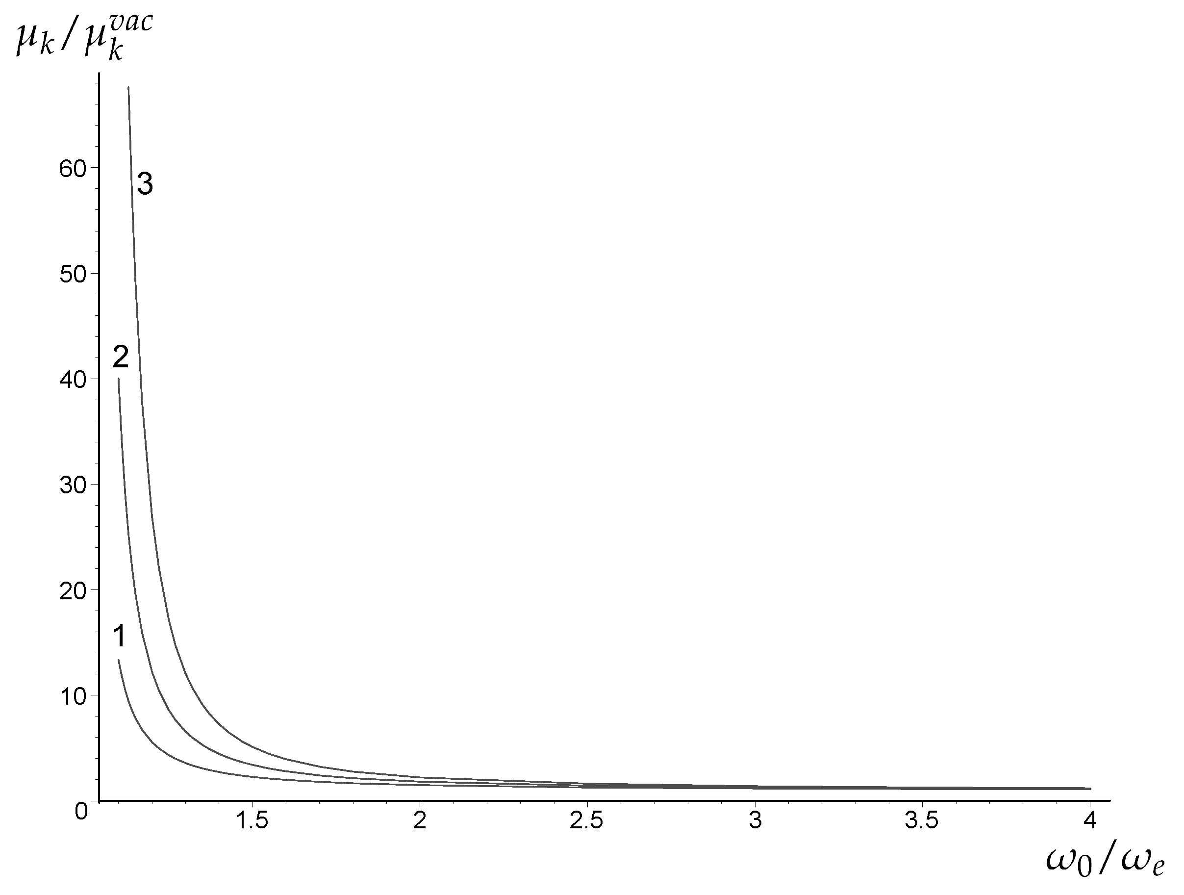
The magnification of the relativistic images of a point source located at the angular position from line connecting the observer and the gravitational center (lens) is equal to [36]
and and are coefficients defined in (28). In the expression (32) the variables , , , depend on x, so these variables depend on the ratio of the photon and the plasma frequencies. Magnification of the relativistic images tends to infinity if the source angular position goes to 0, as it takes place in the vacuum [58]. If , magnifications increases unboundedly, because tends to infinity in this limit, according to (26) and (27), see Figure 8. Although presence of plasma can significantly increase the magnifications in comparison with plasma, the magnification remains very small because vacuum values are very small. For example, for , which corresponds to supermassive black hole in center of Milky Way, , as (these parameters have been taken from [59]) the vacuum values of magnification are [36]:
5. Influence of a Plasma on the Shadow of a Spherically Symmetric Black Hole
5.1. General Formulas for Spherically Symmetric Black Holes
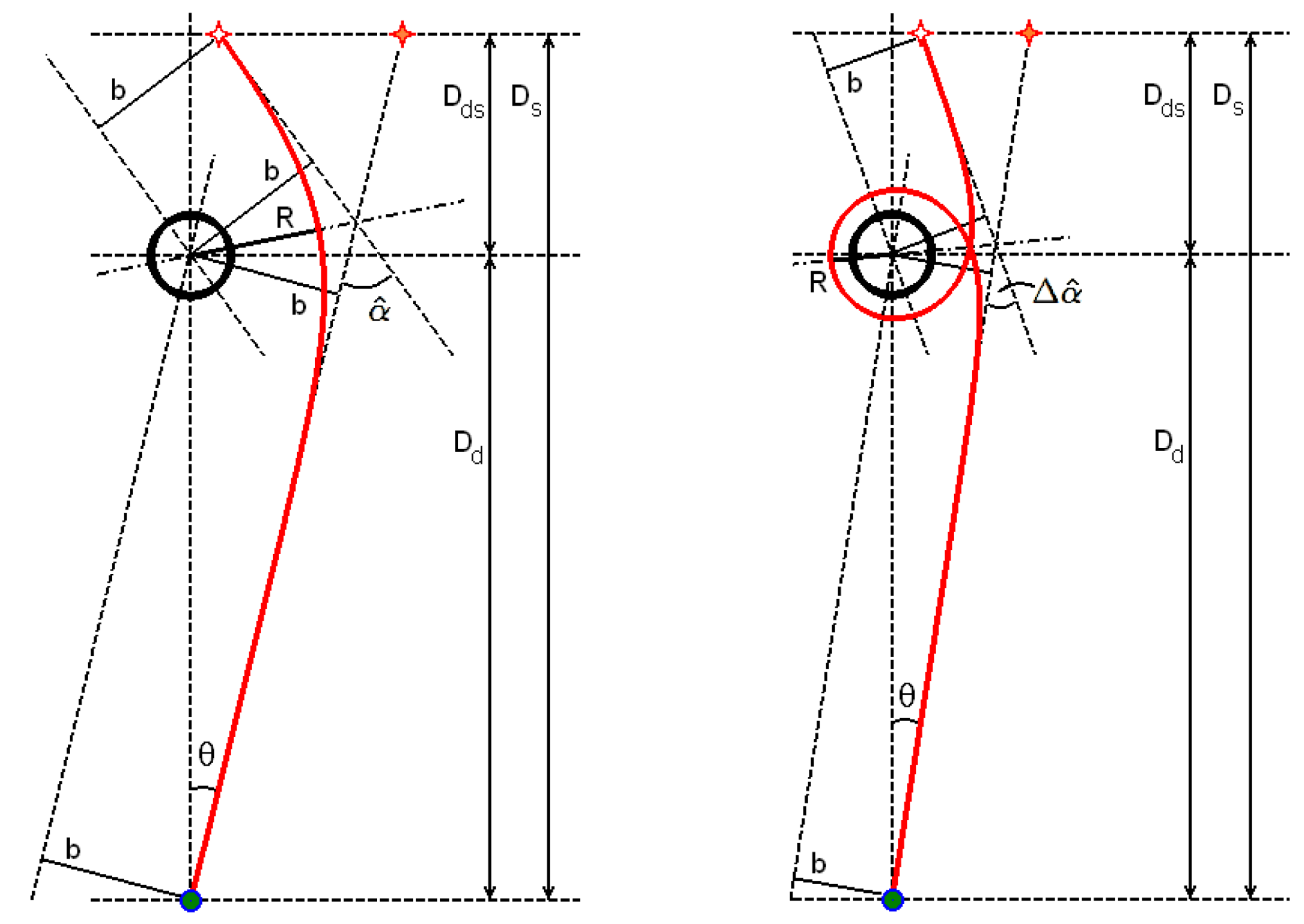
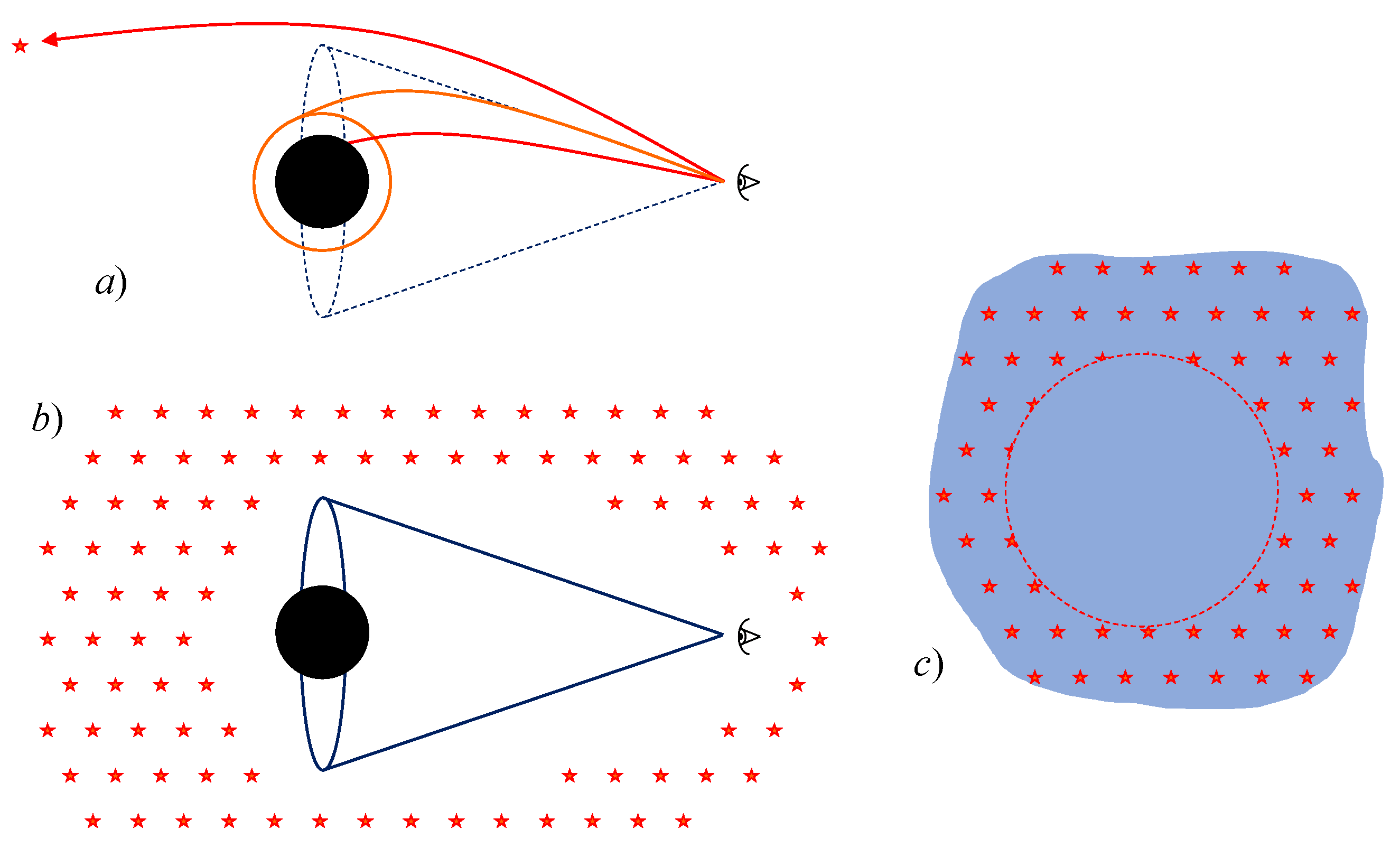
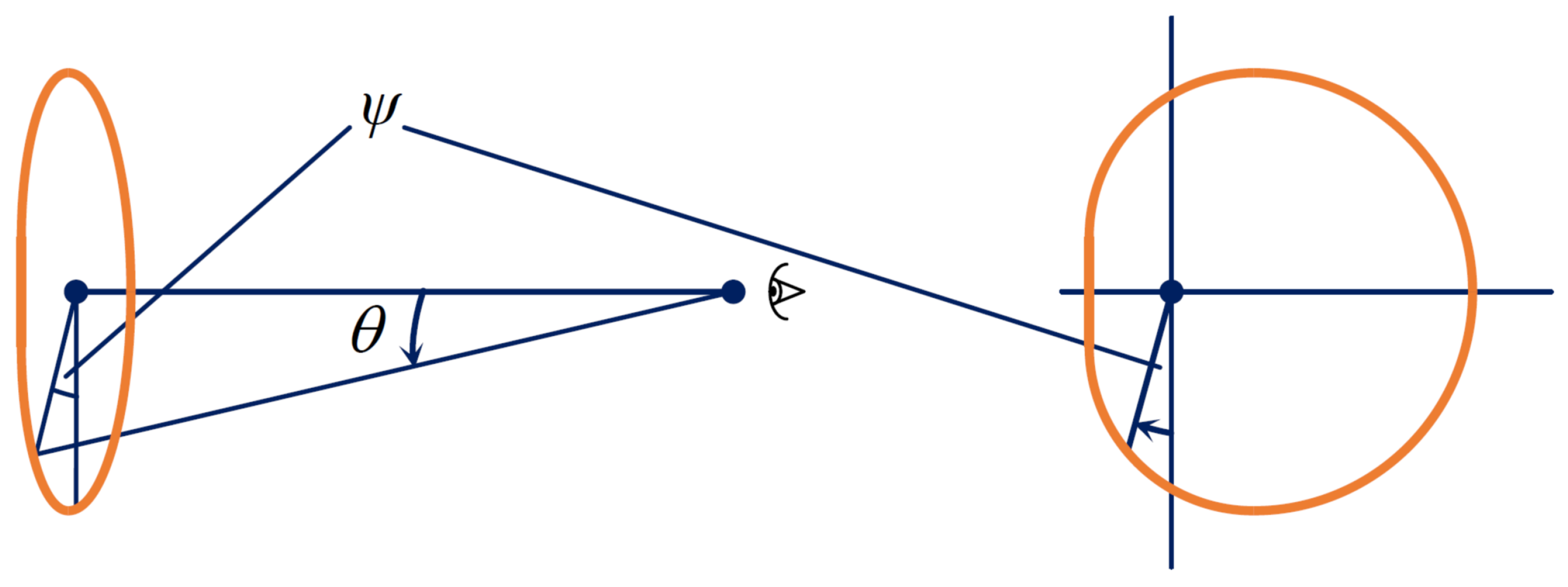
The shadow is defined as the region of the observer’s sky that is left dark if there are light sources distributed everywhere but not between the observer and the black hole. For constructing the shadow we have to consider all past-oriented light rays that issue from a chosen observer position. Each of these light rays corresponds to a point on the observer’s sky. We assign darkness to a point if the corresponding light ray goes to the horizon of the black hole, and brightness otherwise. Observer will see a dark spot (which we call as shadow) in the angular direction where the black hole is located. The boundary of the shadow is determined by the initial directions of light rays that asymptotically spiral towards the outermost photon sphere (see Figure 9 and Figure 10).
The first steps towards an investigation of the shadow in matter based on analytical calculations have been done in the paper of Perlick, Tsupko and Bisnovatyi-Kogan [48]. In that paper we have considered the simplest non-trivial case: the influence of a non-magnetized pressure-less plasma on the size of the shadow of a non-rotating black hole was analytically calculated.
Let us consider a spherically symmetric and static metric (1) with the refraction index (3). Let us define for convenience a function which contains all information about spacetime and plasma and is given by
This is more general definition of function given by (9).
We obtain that the angular radius of the shadow is determined by compact formula [48]:
here is the observer position, and is the radius of photon circular orbit (for given space-time and plasma distribution) and can be found from equation
Any solution of (36) determines the radius of a photon sphere. If a light ray starts tangentially to such a sphere it will stay on a circular path with radius forever.
To find for a given metric of the form (1), a given plasma concentration , a given photon frequency at infinity and a given observer position , we have to calculate using Equation (36) and to substitute the result into Formula (35). Note that the photon frequency at the observer position is according to (4).
5.2. Schwarzschild Black Hole
For the Schwarzschild spacetime,
the function specifies to
The angular radius of the shadow (35) specifies to
where has to be determined from (36) which is simplified to
For vacuum, , our consideration gives
this is Synge’s [83] formula for the radius of the shadow of a Schwarzschild black hole which was mentioned already in the Introduction.
It is shown in paper [55] that the plasma has an increasing effect of the shadow if and only if
Particular cases:
- (i)
- In case of homogeneous plasma const, and condition (42) is always satisfied as . Therefore presence of homogeneous plasma makes the shadow bigger.
- (ii)
- In case of non-homogeneous plasma with given density distribution both increasing and decreasing effects are possible, depending on the position of the observer. Near the black hole, relativistic effects predominate. As we know, gravitational deflection becomes larger in presence of (homogeneous or non-homogeneous) plasma, therefore the shadow becomes larger for the observer who is close to the black hole. Far from the black hole, refraction effects predominate. Refraction on the declining density profile reduces the total deflection angle. Therefore, the shadow becomes smaller for the observer who is far from the black hole. These conclusions are evident from the Formula (42). The factor in brackets on the left-hand side of the inequality is always greater than the factor in brackets on the right-hand side of the inequality, but it does not exceed unity. At the same time, the plasma frequency on the left side of the inequality decreases as the observer moves away from the black hole. This leads to the fact that when the observer is moving further and further from the black hole, the shadow first increases, and after reaching a certain distance (which can be found from equating the left and right parts) decreases. Dependence of this distance on k for power-law distribution (17) is presented in the paper [55].
5.3. Small Density Plasma Case
Special attention was given to the realistic case when the plasma frequency is much smaller than the photon frequency. If the plasma frequency is much smaller than the photon frequency, the equations for the photon sphere and for the radius of the shadow can be linearized around the corresponding values for vacuum light rays. As an example, we consider the Schwarzschild spacetime for the case that the plasma electron density is given by a power law,
where and are dimensionless constants. The first-order equation for the radius of the shadow yields [48]
If the observer is far away from the black hole, , this can be simplified to
Again, we see that the shadow for distant observer becomes bigger in homogeneous plasma and becomes smaller in non-homogeneous one.
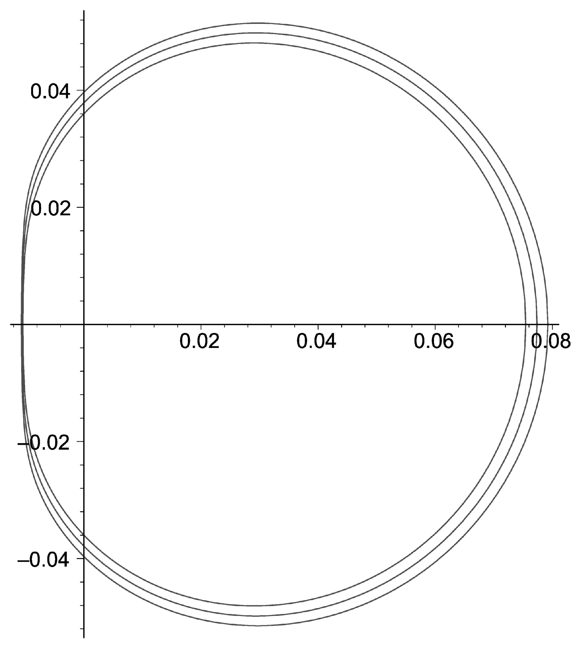
In the presence of a plasma the size of the shadow depends on the wavelength at which the observation is made (Figure 11), in contrast to the vacuum case where it is the same for all wavelengths. Very high photon frequencies corresponds to vacuum case. The difference from the vacuum size of the shadow becomes bigger with decrease of the photon frequency . Dependence of the shadow size on the photon frequency in a homogeneous plasma goes as
and in a non-homogeneous plasma for a distant observer we have
For estimation of the effect, the case of a spherically symmetric accretion of plasma onto a Schwarzschild black hole was considered in detail. We have found that for an observer far away from the Schwarzschild black hole the plasma makes the shadow smaller. As examples, we have considered Sgr A* and M87. Using this specific accretion model and observed luminosities in these systems, we have estimated the plasma density, and found that the effect of the presence of a plasma on the size of the shadow can be significant only for wavelengths of at least a few centimeters. At such wavelengths the observation of the shadow is made difficult because of scattering. For further details see Reference [48].
6. Influence of Plasma on the Shadow of a Kerr Black Hole
As we learned from the last section, in the case of a spherically symmetric black hole, the shadow boundary is determined by the rays coming from the observer and falling on one of the circular orbits filling the photon sphere. The photon sphere is filled with circular orbits of the same radius. In the case of the Kerr black hole, instead of the photon sphere, there is a so called photon region. The photon region is the region in spacetime filled with spherical light rays, i.e., with solutions to the ray equation that stay on a sphere constant. Photon region includes spherical orbits of different radii. Similar to spherically symmetric case, unstable spherical light rays can serve as limit curves for light rays that approach them in a spiral motion.
The shadow in case of Kerr black hole is constructed as follows [85]. The observer sends the rays into the past. Some of them are absorbed by a black hole, others go to infinity. The first type of rays corresponds to the observer’s darkness, the second type of rays corresponds to brightness. The boundary of the shadow is determined by the rays that asymptotically spiral towards one of the unstable spherical light orbits. For every azimuthal angle in the observer’s sky (Figure 12) there exist one spherical orbit with some radius , which leads us to a value of colatitude angle . The set of these orbits determines the shadow of a Kerr black hole. Change of the azimuthal angle corresponds to a change of the parameter from some minimal to some maximum value. Using this way of construction, we can obtain the shadow written in terms of two celestial angles.
In this Section we review results of recent paper of Perlick and Tsupko [55]. Light propagation in a non-magnetized pressureless plasma around a Kerr black hole is considered. We have found the necessary and sufficient condition the plasma electron density has to satisfy, to guarantee that the Hamilton-Jacobi equation for the light rays is separable, i.e., that a generalized Carter constant exists. The shadow of a Kerr black hole under the influence of a plasma, that satisfies the separability condition is calculated. More precisely, an analytical formula for the boundary curve of the shadow on the sky of an observer that is located anywhere in the domain of outer communication is derived.
We consider the Kerr metric, in Boyer-Lindquist coordinates ,
where
Here m is the mass parameter and a is the spin parameter,
where M is the mass and J is the spin. We assume that the plasma electron frequency is a function only of r and .
We have used the Hamiltonian formalism for light rays in a plasma on Kerr spacetime and have determined the necessary and sufficient condition for separability of the Hamilton-Jacobi equation. We have demonstrated that the Hamilton-Jacobi equation is separable, i.e., that a generalized Carter constant exists, only for special distributions of the plasma electron density:
with some functions and .
We have derived analytical formulas for the boundary curve of the shadow on the observer’s sky in terms of two angular celestial coordinates, colatitude and azimuthal angles:
with the constants of motion and K,
With these expressions for and inserted into (53) and (54) we get the boundary of the shadow as a curve on the observer’s sky parametrized by parameter . The boundary curve consists of a lower part, where runs from to , and an upper part where runs from to . The parameter runs from a minimum value to a maximum value and then back to . The values and are determined by the property that then must be equal to 1, i.e., by (54), if
Our formulas are valid for any photon frequency at infinity , for any value of the spin parameter a, for any position of the observer outside of the horizon of the black hole (i.e., with arbitrary distance from the black hole and arbitrary inclination) and for any plasma distribution which satisfies the separability condition.
When plotting the shadow (for example, see Figure 13), we use stereographic projection (see Figure 8 in [85]) onto a plane that is tangent to the celestial sphere at the pole , and in this plane we use dimensionless Cartesian coordinates,
The pole , i.e., the origin of our Cartesian coordinate system, corresponds to a past-oriented ingoing principal null ray through the observer position. This method of plotting the shadow, which was used in [55,85,86], is to be distinguished from the one introduced by Bardeen [84] and used subsequently by many authors. Bardeen considers an observer at infinity with use of impact parameters as the coordinates on the axes, while the presented approach allow any observer position in the domain of outer communication, and coordinates are directly related to angular measures on the observer’s sky. Also, origins of coordinates in these approaches have different positions (of course, the choice of the origin is a matter of convention). One just has to keep in mind that presented way of plotting may be directly compared with Bardeen’s only if the observer is at a big radius coordinate and that the origin is horizontally shifted, for details see text after formula (57) in paper [55].
For the reader’s convenience, we have written a step-by-step procedure for the construction of the shadow [55].
- Choose the mass parameter m and the spin parameter a with . The mass parameter m gives a natural length unit, i.e., all other lengths may be given in units of m.
- Choose a plasma frequency around the black hole. The plasma frequency has to satisfy the separability condition (52), so the plasma distribution is characterized by two functions and . Only for such plasma frequencies are the ray equations completely integrable and the shadow can be calculated analytically.
- Choose a position of an observer anywhere in the domain of outer communication by prescribing its radial and angular coordinate and . For an illustration see Figure 7 in [85].
- Choose the constant of motion for the rays that are to be considered. In the formulas for the shadow, will enter only in terms of the quotient . Therefore, it is convenient to give and as multiples of the same frequency unit which will then drop out from all relevant formulas.
- Substitute into the expressions for and the expressions and according to Formulas (55) and (56) with . Here runs over an interval of radius coordinates for which unstable spherical light rays exist. This gives us and as functions of , i.e., it gives us a curve on the observer’s sky. This is the boundary curve of the shadow. In the next two steps we determine the range of the curve parameter .
- Solve the equation for . This gives us the minimal value . If the plasma density is small and if the observer is in the equatorial plane, for small a it will be , while for a nearly extreme Kerr black hole () it will be .
- Solve the equation for . This gives us the maximal value . If the plasma density is small, for small a it will be , while for a nearly extreme Kerr black hole it will be .
- Calculate and where ranges over the interval .Note that gives the horizontal diameter of the shadow.
- Calculate the dimensionless Cartesian coordinates X and Y of the boundary curve of the shadow by Formula (58). Choosing and letting run from to gives the lower half of the boundary curve of the shadow. The upper half of the curve is the mirror image of the lower half with respect to a horizontal axis.
7. Conclusions
- (i)
- Assuming that the influence of both gravity and plasma on the trajectory is small, the total deflection angle can be calculated as the sum of individual effects: gravitational deflection and refraction, both angles are small. Effects of deflection by gravity in vacuum and the refractive deflection in non-homogeneous medium are well known and presented in literature with necessary details.
- (ii)
- In the case of a strong gravitational field and for the study of subtle effects, a self-consistent theory of gravitation in matter is necessary. In presence of both gravity and plasma the deflection angle is physically defined by mutual combination of different phenomena: gravity, dispersion, refraction.
- (iii)
- New effect is that in the case of a homogeneous plasma, in absence of refractive deflection, the gravitational deflection itself differs from the vacuum deflection and depends on the photon frequency. Presence of plasma makes the gravitational deflection bigger.
- (iv)
- Plasma is a dispersive medium, its refractive index depends on the photon frequency. Therefore the deflection angle in presence of both gravity and plasma always depends on the photon frequency. In particular, presence of homogeneous plasma leads to chromatic gravitational deflection; the presence of non-homogeneous plasma leads, in addition to the chromatic gravitational deflection, to a chromatic refractive deflection. Refractive deflection on the density profile falling radially outwards is opposite to the chromatic gravitational deflection by central mass.
- (v)
- Presence of plasma makes gravitational lensing chromatic and leads to difference in angular position of the same image at different wavelengths. With present level of technique, the chromatic plasma effects might be observed only in strong lens systems. All chromatic effects are significant only for very long radiowaves.
- (vi)
- The deflection angles for light rays near Schwarzschild black hole in homogeneous plasma, in strong deflection limit, are derived. Using of strong deflection limit allows us to investigate analytically properties of relativistic images in presence of plasma.
- (vii)
- Analytical formula for the angular size of the shadow in a plasma with a spherically symmetric density distribution on a spherically symmetric and static spacetime is derived. In the presence of a plasma the size of the black hole shadow depends on the wavelength at which the observation is made, in contrast to the vacuum case where it is the same for all wavelengths. In homogeneous plasma, the shadow becomes bigger for distant observer, in comparison with vacuum case. In non-homogeneous plasma, the shadow becomes smaller for distant observer. As examples, we have considered Sgr A* and M87, and found that the effect of the presence of a plasma on the size of the shadow can be significant only for wavelengths of at least a few centimeters (radio regime).
- (viii)
- The propagation of light rays in a non-magnetized pressureless plasma on Kerr spacetime is investigated. We have demonstrated that the Hamilton-Jacobi equation is separable, i.e., that a generalized Carter constant exists, only for special distributions of the plasma electron density. We have derived analytical formulas for the boundary curve of the shadow on the observers sky in terms of two angular celestial coordinates.
Acknowledgments
This work was supported by Russian Science Foundation, Grant No. 15-12-30016. We would like to thank our collaborator and friend Volker Perlick for many valuable discussions, especially for introducing us to the subject of black hole shadow. We are also thankful to the four anonymous Referees for their extremely careful reading of the present manuscript and a number of valuable comments.
Author Contributions
Authors contribute equally to present work.
Conflicts of Interest
The authors declare no conflict of interest. The founding sponsors had no role in the design of the study; in the collection, analyses, or interpretation of data; in the writing of the manuscript, and in the decision to publish the results.
References
- Schneider, P.; Ehlers, J.; Falco, E.E. Gravitational Lenses; Springer: Berlin, Germany, 1992. [Google Scholar]
- Schneider, P.; Kochanek, C.S.; Wambsganss, J. Gravitational Lensing: Strong, Weak and Micro; Swiss Society for Astrophysics and Astronomy Series: Saas-Fee Advanced Courses; Springer: Berlin, Germany, 2006; p. 33. [Google Scholar]
- Perlick, V. Gravitational Lensing from a Spacetime Perspective. Living Rev. Relativ. 2004, 7, 9. [Google Scholar] [CrossRef] [PubMed]
- Mao, S. Astrophysical applications of gravitational microlensing. Res. Astron. Astrophys. 2012, 12, 947–972. [Google Scholar] [CrossRef]
- Bartelmann, M.; Schneider, P. Weak gravitational lensing. Phys. Rep. 2001, 340, 291–472. [Google Scholar] [CrossRef]
- Bartelmann, M. Gravitational lensing. Class. Quantum Gravity 2010, 27, 233001. [Google Scholar] [CrossRef]
- Wambsganss, J. Gravitational Lensing in Astronomy. Living Rev. Relativ. 1998, 1, 12. [Google Scholar] [CrossRef]
- Hoekstra, H.; Jain, B. Weak Gravitational Lensing and Its Cosmological Applications. Annu. Rev. Nucl. Part. Sci. 2008, 58, 99–123. [Google Scholar] [CrossRef]
- Refsdal, S. The gravitational lens effect. Mon. Not. R. Astron. Soc. 1964, 128, 295–306. [Google Scholar] [CrossRef]
- Refsdal, S. On the possibility of determining Hubble’s parameter and the masses of galaxies from the gravitational lens effect. Mon. Not. R. Astron. Soc. 1964, 128, 307–310. [Google Scholar] [CrossRef]
- Byalko, A.V. Focusing of Radiation by a Gravitational Field. Astronomicheskii Zhurnal 1969, 46, 998–1002, (English translation: Sov. Astron. 1970, 13, 784–787.). [Google Scholar]
- Clark, E.E. The uniform transparent gravitational lens. Mon. Not. R. Astron. Soc. 1972, 158, 233–243. [Google Scholar] [CrossRef]
- Mao, S.; Paczyński, B. Gravitational microlensing by double stars and planetary systems. Astrophys. J. 1991, 374, L37–L40. [Google Scholar] [CrossRef]
- Nucita, A.A.; Giordano, M.; De Paolis, F.; Ingrosso, G. Signatures of rotating binaries in microlensing experiments. Mon. Not. R. Astron. Soc. 2014, 438, 2466–2473. [Google Scholar] [CrossRef]
- Alexandrov, A.N.; Zhdanov, V.I.; Fedorova, E.V. Asymptotic formulas for the magnification of a gravitational lens system near a fold caustic. Astron. Lett. 2010, 36, 329–337. [Google Scholar] [CrossRef]
- Alexandrov, A.N.; Zhdanov, V.I. Asymptotic expansions and amplification of a gravitational lens near a fold caustic. Mon. Not. R. Astron. Soc. 2011, 417, 541–554. [Google Scholar] [CrossRef]
- Er, X.; Li, G.; Mao, S.; Cao, L. Gravitational lensing effects on submillimetre galaxy counts. Mon. Not. R. Astron. Soc. 2013, 430, 1423–1432. [Google Scholar] [CrossRef]
- Clowe, D.; Bradač, M.; Gonzalez, A.H.; Markevitch, M.; Randall, S.W.; Jones, C.; Zaritsky, D. A Direct Empirical Proof of the Existence of Dark Matter. Astrophys. J. 2006, 648, L109–L113. [Google Scholar] [CrossRef]
- Kayser, R.; Refsdal, S.; Stabell, R. Astrophysical applications of gravitational micro-lensing. Astron. Astrophys. 1986, 166, 36–52. [Google Scholar]
- Wambsganss, J.; Paczyński, B. Expected color variations of the gravitationally microlensed QSO 2237+0305. Astron. J. 1991, 102, 864–868. [Google Scholar] [CrossRef]
- Bogdanov, M.V.; Cherepashchuk, A.M. The “chromatic” effect in gravitational microlensing of stars. Astron. Lett. 1995, 21, 505–507. [Google Scholar]
- Bogdanov, M.B.; Cherepashchuk, A.M. Reconstruction of the Strip Brightness Distribution in a Quasar Accretion Disk from Gravitational Microlensing Data. Astron. Rep. 2002, 46, 626–633. [Google Scholar] [CrossRef]
- Zakharov, A.F.; Sazhin, M.V. Gravitational microlensing. Phys. Uspekhi 1998, 41, 945–982. [Google Scholar] [CrossRef]
- Landau, L.D.; Lifshitz, E.M. Electrodynamics of Continuous Media, Course of Theoretical Physics; Pergamon Press: Oxford, UK, 1960. [Google Scholar]
- Zhelezniakov, V.V. Electromagnetic Waves in Space Plasma: Generation and Propagation; Nauka: Moscow, Russia, 1977. (In Russian) [Google Scholar]
- Muhleman, D.O.; Ekers, R.D.; Fomalont, E.B. Radio Interferometric Test of the General Relativistic Light Bending Near the Sun. Phys. Rev. Lett. 1970, 24, 1377–1380. [Google Scholar] [CrossRef]
- Muhleman, D.O.; Johnston, I.D. Radio Propagation in the Solar Gravitational Field. Phys. Rev. Lett. 1966, 17, 455–458. [Google Scholar] [CrossRef]
- Lightman, A.P.; Press, W.H.; Price, R.H.; Teukolsky, S.A. Problem Book in Relativity and Gravitation; Princeton University Press: Princeton, NJ, USA, 1979. [Google Scholar]
- Bliokh, P.V.; Minakov, A.A. Gravitational Lenses; Naukova: Dumka, India, 1989. (In Russian) [Google Scholar]
- Synge, J.L. Relativity: The General Theory; North-Holland Publishing Company: Amsterdam, The Netherlands, 1960. [Google Scholar]
- Bičák, J.; Hadrava, P. General-relativistic radiative transfer theory in refractive and dispersive media. Astron. Astrophys. 1975, 44, 389–399. [Google Scholar]
- Kichenassamy, S.; Krikorian, R.A. Relativistic radiation transport in dispersive media. Phys. Rev. D 1985, 32, 1866–1870. [Google Scholar] [CrossRef]
- Krikorian, R.A. Light rays in gravitating and refractive media: A comparison of the field to particle and Hamiltonian approaches. Astrophysics 1999, 42, 338–343. [Google Scholar] [CrossRef]
- Kulsrud, R.; Loeb, A. Dynamics and gravitational interaction of waves in nonuniform media. Phys. Rev. D 1992, 45, 525–531. [Google Scholar] [CrossRef]
- Perlick, V. Ray Optics, Fermat’s Principle and Applications to General Relativity; Springer: Heidelberg, Germany, 2000. [Google Scholar]
- Tsupko, O.Y.; Bisnovatyi-Kogan, G.S. Gravitational lensing in plasma: Relativistic images at homogeneous plasma. Phys. Rev. D 2013, 87, 124009. [Google Scholar] [CrossRef]
- Bisnovatyi-Kogan, G.S.; Tsupko, O.Y. Gravitational lensing in plasmic medium. Plasma Phys. Rep. 2015, 41, 562–581. [Google Scholar] [CrossRef]
- Breuer, R.A.; Ehlers, J. Propagation of high frequency waves through a magnetized plasma in curved space-time. I. Proc. R. Soc. Lond. A 1980, 370, 389–406. [Google Scholar] [CrossRef]
- Breuer, R.A.; Ehlers, J. Propagation of high-frequency electromagnetic waves through a magnetized plasma in curved space-time. II-Application of the asymptotic approximation. Proc. R. Soc. Lond. A 1981, 374, 65–86. [Google Scholar] [CrossRef]
- Breuer, R.A.; Ehlers, J. Propagation of electromagnetic waves through magnetized plasmas in arbitrary gravitational fields. Astron. Astrophys. 1981, 96, 293–295. [Google Scholar]
- Broderick, A.; Blandford, R. Covariant magnetoionic theory-I. Ray propagation. Mon. Not. R. Astron. Soc. 2003, 342, 1280–1290. [Google Scholar] [CrossRef]
- Broderick, A.; Blandford, R. Covariant magnetoionic theory-II. Radiative transfer. Mon. Not. R. Astron. Soc. 2004, 349, 994–1008. [Google Scholar] [CrossRef]
- Broderick, A.; Blandford, R. General Relativistic Magnetoionic Theory. Astrophys. Space Sci. 2003, 288, 161–173. [Google Scholar] [CrossRef]
- Bisnovatyi-Kogan, G.S.; Tsupko, O.Y. Gravitational radiospectrometer. Gravit. Cosmol. 2009, 15, 20–27. [Google Scholar] [CrossRef]
- Bisnovatyi-Kogan, G.S.; Tsupko, O.Y. Gravitational lensing in a non-uniform plasma. Mon. Not. R. Astron. Soc. 2010, 404, 1790–1800. [Google Scholar] [CrossRef]
- Morozova, V.S.; Ahmedov, B.J.; Tursunov, A.A. Gravitational lensing by a rotating massive object in a plasma. Astrophys. Space Sci. 2013, 346, 513–520. [Google Scholar] [CrossRef]
- Er, X.; Mao, S. Effects of plasma on gravitational lensing. Mon. Not. R. Astron. Soc. 2014, 437, 2180–2186. [Google Scholar] [CrossRef]
- Perlick, V.; Tsupko, O.Y.; Bisnovatyi-Kogan, G.S. Influence of a plasma on the shadow of a spherically symmetric black hole. Phys. Rev. D 2015, 92, 104031. [Google Scholar] [CrossRef]
- Rogers, A. Frequency-dependent effects of gravitational lensing within plasma. Mon. Not. R. Astron. Soc. 2015, 451, 17–25. [Google Scholar] [CrossRef]
- Rogers, A. Gravitational lensing by compact objects within plasma. arXiv 2016, arXiv:1611.00076. [Google Scholar]
- Rogers, A. Escape and Trapping of Low-Frequency Gravitationally Lensed Rays by Compact Objects within Plasma. Mon. Not. R. Astron. Soc. 2017, 465, 2151–2159. [Google Scholar] [CrossRef]
- Rogers, A. Gravitational Lensing of Rays through the Levitating Atmospheres of Compact Objects. Universe 2017, 3, 3. [Google Scholar] [CrossRef]
- Hakimov, A.; Atamurotov, F. Gravitational lensing by a non-Schwarzschild black hole in a plasma. Astrophys. Space Sci. 2016, 361, 112. [Google Scholar] [CrossRef]
- Liu, C.; Ding, C.; Jing, J. Effects of Homogeneous Plasma on Strong Gravitational Lensing of Kerr Black Holes. arXiv 2016, arXiv:1610.02128. [Google Scholar]
- Perlick, V.; Tsupko, O.Y. Light propagation in a plasma on Kerr spacetime: Separation of the Hamilton-Jacobi equation and calculation of the shadow. Phys. Rev. D 2017, 95, 104003. [Google Scholar] [CrossRef]
- Darwin, C. The Gravity Field of a Particle. Proc. R. Soc. Lond. Ser. A Math. Phys. Sci. 1959, 249, 180–194. [Google Scholar] [CrossRef]
- Bisnovatyi-Kogan, G.S.; Tsupko, O.Y. Strong gravitational lensing by Schwarzschild black holes. Astrophysics 2008, 51, 99–111. [Google Scholar] [CrossRef]
- Virbhadra, K.S.; Ellis, G.F.R. Schwarzschild black hole lensing. Phys. Rev. D 2000, 62, 084003. [Google Scholar] [CrossRef]
- Virbhadra, K.S. Relativistic images of Schwarzschild black hole lensing. Phys. Rev. D 2009, 79, 083004. [Google Scholar] [CrossRef]
- Perlick, V. Exact gravitational lens equation in spherically symmetric and static spacetimes. Phys. Rev. D 2004, 69, 064017. [Google Scholar] [CrossRef]
- Bozza, V.; Capozziello, S.; Iovane, G.; Scarpetta, G. Strong Field Limit of Black Hole Gravitational Lensing. Gen. Relativ. Gravit. 2001, 33, 1535–1548. [Google Scholar] [CrossRef] [Green Version]
- Bozza, V. Gravitational lensing in the strong field limit. Phys. Rev. D 2002, 66, 103001. [Google Scholar] [CrossRef]
- Perlick, V. Theoretical gravitational lensing. Beyond the weak-field small-angle approximation. In Proceedings of the MG11 Meeting on General Relativity, Berlin, Germany, 23–29 July 2006; Kleinert, H., Jantzen, R.T., Ruffini, R., Eds.; World Scientific: Singapore, 2008; pp. 680–699. [Google Scholar]
- Hasse, W.; Perlick, V. Gravitational lensing in spherically symmetric static space-times with centrifugal force reversal. Gen. Relativ. Gravit. 2002, 34, 415–433. [Google Scholar] [CrossRef]
- Claudel, C.-M.; Virbhadra, K.S.; Ellis, G.F.R. The geometry of photon surfaces. J. Math. Phys. 2001, 42, 818–838. [Google Scholar] [CrossRef]
- Virbhadra, K.S.; Keeton, C.R. Time delay and magnification centroid due to gravitational lensing by black holes and naked singularities. Phys. Rev. D 2008, 77, 124014. [Google Scholar] [CrossRef]
- Bozza, V. Comparison of approximate gravitational lens equations and a proposal for an improved new one. Phys. Rev. D 2008, 78, 103005. [Google Scholar] [CrossRef]
- Bozza, V. Gravitational lensing by black holes. Gen. Relativ. Gravit. 2010, 42, 2269–2300. [Google Scholar] [CrossRef]
- Eiroa, E.F.; Romero, G.E.; Torres, D.F. Reissner-Nordström black hole lensing. Phys. Rev. D 2002, 66, 024010. [Google Scholar] [CrossRef]
- Iyer, S.V.; Petters, A.O. Light’s bending angle due to black holes: From the photon sphere to infinity. Gen. Relativ. Gravit. 2007, 39, 1563–1582. [Google Scholar] [CrossRef]
- Eiroa, E.F.; Sendra, C.M. Gravitational lensing by a regular black hole. Class. Quantum Gravity 2011, 28, 085008. [Google Scholar] [CrossRef]
- Mukherjee, N.; Majumdar, A.S. Rotating brane-world black hole lensing in the strong deflection limit. Grav. Cosmol. 2009, 15, 263–272. [Google Scholar] [CrossRef]
- Ghosh, T.; Sengupta, S. Strong gravitational lensing across a dilaton anti-de Sitter black hole. Phys. Rev. D 2010, 81, 044013. [Google Scholar] [CrossRef]
- Wei, S.-W.; Liu, Y.-X.; Fu, C.-E.; Yang, K. Strong field limit analysis of gravitational lensing in Kerr-Taub-NUT spacetime. J. Cosmol. Astropart. Phys. 2012, 2012, 053. [Google Scholar] [CrossRef]
- Tarasenko, A. Reconstruction of a compact object motion in the vicinity of a black hole by its electromagnetic radiation. Phys. Rev. D 2010, 81, 123005. [Google Scholar] [CrossRef]
- Li, G.; Zhang, Ya.; Zhang, L.; Feng, Z.; Zu, X. Strong Gravitational Lensing in the Einstein-Proca Theory. Int. J. Theor. Phys. 2015, 54, 1245–1252. [Google Scholar] [CrossRef]
- Alhamzawi, A.; Alhamzawi, R. Gravitational lensing in the strong field limit by modified gravity. Gen. Relativ. Gravit. 2016, 48, 167. [Google Scholar] [CrossRef]
- Tsukamoto, N. Strong deflection limit analysis and gravitational lensing of an Ellis wormhole. Phys. Rev. D 2016, 94, 124001. [Google Scholar] [CrossRef]
- Zakharov, A.F. Effective particle capture cross section of a Schwarzschild black hole. Sov. Astron. 1988, 32, 456. [Google Scholar]
- Zakharov, A.F. Particle capture cross sections for a Reissner-Nordström black hole. Class. Quantum Gravity 1994, 11, 1027–1033. [Google Scholar] [CrossRef]
- Tsupko, O.Y. Unbound motion of massive particles in the Schwarzschild metric: Analytical description in case of strong deflection. Phys. Rev. D 2014, 89, 084075. [Google Scholar] [CrossRef]
- Liu, X.; Yang, N.; Jia, J. Gravitational lensing of massive particles in Schwarzschild gravity. Class. Quantum Gravity 2016, 33, 175014. [Google Scholar] [CrossRef]
- Synge, J.L. The escape of photons from gravitationally intense stars. Mon. Not. R. Astron. Soc. 1966, 131, 463–466. [Google Scholar] [CrossRef]
- Bardeen, J.M. Timelike and null geodesics in the Kerr metric. In Black Holes; DeWitt, C., DeWitt, B., Eds.; Gordon and Breach: New York, NY, USA, 1973. [Google Scholar]
- Grenzebach, A.; Perlick, V.; Lämmerzahl, C. Photon regions and shadows of Kerr-Newman-NUT black holes with a cosmological constant. Phys. Rev. D 2014, 89, 124004. [Google Scholar] [CrossRef]
- Grenzebach, A.; Perlick, V.; Lämmerzahl, C. Photon regions and shadows of accelerated black holes. Int. J. Mod. Phys. D 2015, 24, 1542024. [Google Scholar] [CrossRef]
- Luminet, J.-P. Image of a spherical black hole with thin accretion disk. Astron. Astrophys. 1979, 75, 228–235. [Google Scholar]
- Chandrasekhar, S. The Mathematical Theory of Black Holes; Oxford University Press: New York, NY, USA, 1983. [Google Scholar]
- Dymnikova, I.G. Motion of particles and photons in the gravitational field of a rotating body (In memory of Vladimir Afanas’evich Ruban). Sov. Phys. Uspekhi 1986, 29, 215–237. [Google Scholar] [CrossRef]
- Falcke, H.; Melia, F.; Agol, E. Viewing the shadow of the black hole at the galactic center. Astrophys. J. 2000, 528, L13–L16. [Google Scholar] [CrossRef] [PubMed]
- Takahashi, R. Shapes and Positions of Black Hole Shadows in Accretion Disks and Spin Parameters of Black Holes. Astrophys. J. 2004, 611, 996–1004. [Google Scholar] [CrossRef]
- Zakharov, A.F.; de Paolis, F.; Ingrosso, G.; Nucita, A.A. Direct measurements of black hole charge with future astrometrical missions. Astron. Astrophys. 2005, 442, 795–799. [Google Scholar] [CrossRef]
- Zakharov, A.F.; Nucita, A.A.; DePaolis, F.; Ingrosso, G. Measuring the black hole parameters in the galactic center with RADIOASTRON. New Astron. 2005, 10, 479–489. [Google Scholar] [CrossRef]
- Hioki, K.; Maeda, K.-I. Measurement of the Kerr spin parameter by observation of a compact object’s shadow. Phys. Rev. D 2009, 80, 024042. [Google Scholar] [CrossRef]
- Frolov, V.P.; Zelnikov, A. Introduction to Black Hole Physics; Oxford University Press: Oxford, UK, 2011. [Google Scholar]
- Zakharov, A.F.; De Paolis, F.; Ingrosso, G.; Nucita, A.A. Shadows as a tool to evaluate black hole parameters and a dimension of spacetime. New Astron. Rev. 2012, 56, 64–73. [Google Scholar] [CrossRef]
- Bambi, C.; Modesto, L. Rotating regular black holes. Phys. Lett. B 2013, 721, 329–334. [Google Scholar] [CrossRef]
- Li, Z.; Bambi, C. Measuring the Kerr spin parameter of regular black holes from their shadow. J. Cosmol. Astropart. Phys. 2014, 2014, 41. [Google Scholar] [CrossRef]
- Tsukamoto, N.; Li, Z.; Bambi, C. Constraining the spin and the deformation parameters from the black hole shadow. J. Cosmol. Astropart. Phys. 2014, 2014, 043. [Google Scholar] [CrossRef]
- Zakharov, A.F. Constraints on a charge in the Reissner-Nordström metric for the black hole at the Galactic Center. Phys. Rev. D 2014, 90, 062007. [Google Scholar] [CrossRef]
- James, O.; von Tunzelmann, E.; Franklin, P.; Thorne, K.S. Gravitational lensing by spinning black holes in astrophysics, and in the movie Interstellar. Class. Quantum Gravity 2015, 32, 065001. [Google Scholar] [CrossRef]
- Abdujabbarov, A.A.; Rezzolla, L.; Ahmedov, B.J. A coordinate-independent characterization of a black hole shadow. Mon. Not. R. Astron. Soc. 2015, 454, 2423–2435. [Google Scholar] [CrossRef]
- Konoplya, R.; Rezzolla, L.; Zhidenko, A. General parametrization of axisymmetric black holes in metric theories of gravity. Phys. Rev. D 2016, 93, 064015. [Google Scholar] [CrossRef]
- Younsi, Z.; Zhidenko, A.; Rezzolla, L.; Konoplya, R.; Mizuno, Y. New method for shadow calculations: Application to parametrized axisymmetric black holes. Phys. Rev. D 2016, 94, 084025. [Google Scholar] [CrossRef]
- Johannsen, T.; Broderick, A.E.; Plewa, P.M.; Chatzopoulos, S.; Doeleman, S.S.; Eisenhauer, F.; Johnson, M.D. Testing General Relativity with the Shadow Size of Sgr A*. Phys. Rev. Lett. 2016, 116, 031101. [Google Scholar] [CrossRef] [PubMed]
- Yang, L.; Li, Z. Shadow of a dressed black hole and determination of spin and viewing angle. Int. J. Mod. Phys. D 2016, 25, 1650026. [Google Scholar] [CrossRef]
- Dastan, S.; Saffari, R.; Soroushfar, S. Shadow of a Charged Rotating Black Hole in f (R) Gravity. arXiv 2016, arXiv:1606.06994. [Google Scholar]
- Abdujabbarov, A.; Amir, M.; Ahmedov, B.; Ghosh, S.G. Shadow of rotating regular black holes. Phys. Rev. D 2016, 93, 104004. [Google Scholar] [CrossRef]
- Abdujabbarov, A.; Juraev, B.; Ahmedov, B.; Stuchlík, Z. Shadow of rotating wormhole in plasma environment. Astrophys. Space Sci. 2016, 361, 226. [Google Scholar] [CrossRef]
- Tsupko, O.Y. Analytical calculation of black hole spin using deformation of the shadow. Phys. Rev. D 2017, 95, 104058. [Google Scholar] [CrossRef]
- Goddi, C.; Falcke, H.; Kramer, M.; Rezzolla, L.; Brinkerink, C.; Bronzwaer, T.; Eatough, R.P. BlackHoleCam: Fundamental physics of the galactic center. Int. J. Mod. Phys. D 2017, 26, 1730001. [Google Scholar] [CrossRef]
- Misner, C.W.; Thorne, K.S.; Wheeler, J.A. Gravitation; Freeman: New York, NY, USA, 1973. [Google Scholar]
| 1. | We call here as a “strong lens system” a lens with several visible images of the same source, but the deflection angle remains to be small. This situation should not be confused with “lensing in strong deflection (or strong gravity) regime” when the deflection angles of photons are not small and approximate Einstein formula can not be applied. |
| 2. | This is true for the massive particle energy and the photon frequency at infinity, and also for static observer at another locations because the particle energy and the photon frequency have the same dependence on the space coordinates arising due to the gravitational field [112]. |
| 3. | We assume that typical size of considered systems is much larger than Debye radius, and therefore temperature effects in dispersion relations are neglected. |
| 4. | In the most parts of this paper we use a convention . Since the constants G and c are not included in the plasma frequency , it looks just the same as in Gaussian cgs units. To calculate the numerical value of plasma frequency, we can just use all variables in the right hand side of (2) in Gaussian cgs units. For reader’s convenience, it can be used: sec where N is measured in cm [25]. At the same time, for numerical estimates in formulas containing the black hole mass M we need to restore the factors of c and G. See, for example, Formulas (68), (69) and (77) in [48]. |
Figure 1.
Effects similar to the effects of gravitational lensing but arising from the non-homogeneity of the medium: (a) Change in the visible position of the object due to the refraction of light at the interface between two media. (b) The emergence of two images of the same object when placed near a mirror.

Figure 2.
Formation of multiple images of the same source by gravitational lensing in vacuum. The left picture shows a general geometry of the problem and trajectories of the light rays. The right picture demonstrates the positions of images at the observer’s sky. A dashed circle is the Einstein-Chwolson ring.

Figure 3.
Schematic representation of trajectories of light rays incident from infinity toward a black hole with different impact parameters. Photons with are absorbed by the black hole. The photons within after approaching black hole flies off to infinity. Light rays with are travelling to a photon sphere which contains unstable photon circular orbits. For the Schwarzschild space-time the Schwarzschild radius equals to , the photon sphere radius equals to , and critical impact parameter equals to . In case , the photon deflection angle is small and can be calculated by approximate Einstein formula .

Figure 4.
Scheme of formation of primary (left) and high-order (right) images of source in case of gravitational lensing by black hole in vacuum. Trajectories of light rays are calculated in the Schwarzschild metric. Light ray from the source deflected by the point-mass gravitational lens goes to the observer. The observer sees the image of the source at angular position , which is different from the real source position. R is the closest point of trajectory to gravitating center, it is usually referred as the distance of the closest approach, b is the impact parameter of the photon, is the distance between observer and lens, is the distance between observer and source, is the distance between lens and source. In case of high-order image (right), the light ray from the source is deflected by angle , and the impact parameter b is close to its critical value .

Figure 5.
Scheme of formation of Einstein ring and relativistic rings by black hole lensing.

Figure 6.
Comparison of lensing by point mass in vacuum (left) and in plasma (middle and right). The photon trajectories and deflection angles in vacuum don’t depend on the photon frequency (or energy). Therefore lensing in vacuum is achromatic, and the Schwarzschild point-mass lens leads to two images with complicated spectra, formed by the photons of different frequencies which undergo deflection by the same angle. If lens is surrounded by plasma, the light rays of different frequencies have different deflection angles. The images become diffused and divide into many images formed by photons of different frequencies. Difference in angular position of images of different frequencies take place both in homogeneous and non-homogeneous plasma and is a subject for observation. On the left figure we present the vacuum lensing: a blue circle is the source, a black spot is the lens, a dashed circle is the Einstein ring. In the middle we present schematic picture for the situation when lens is surrounded by homogeneous plasma, see Section 2.2. Now blue color is used for images with formally infinite photon frequency (for optical frequencies the effect of plasma presence is negligible so for these frequencies it corresponds to vacuum case). Photons of lower frequencies (green and red colors) undergo plasma influence and their deflection angles becomes larger. Therefore green and red images are further from the center of the picture. Angular separation between two images of the same color becomes larger with decrease of the wave frequency (or increase of the wavelength). On the right picture we present the situation when the lens is surrounded by non-homogeneous plasma, and refraction effects prevail over effects of additional gravitational deflection due to plasma, see Section 2.3. Now plasma presence leads to decrease of the total deflection, therefore green and red images are located closer to the center of the picture. Angular separation between two images of the same color becomes smaller with decrease of the photon frequency. This case might be observed by modern facilities. Note that in these pictures we assume that the number and structure of the images do not change drastically due to the presence of plasma. In these pictures we also assume that the emission regions of the source in different bands coincide, which may not necessarily be the case in observations.

Figure 7.
Relativistic images in the case of lensing by black hole surrounded by homogeneous plasma. Two images and corresponding light rays of different wavelengths are calculated.
Figure 7.
Relativistic images in the case of lensing by black hole surrounded by homogeneous plasma. Two images and corresponding light rays of different wavelengths are calculated.

Figure 8.
Comparison of the magnification factors of relativistic images for lensing in homogeneous plasma and in vacuum. Ratios are plotted as a function of , for . Here is the vacuum value of magnification. Values and depend on , , , , , but ratio depends only on .
Figure 8.
Comparison of the magnification factors of relativistic images for lensing in homogeneous plasma and in vacuum. Ratios are plotted as a function of , for . Here is the vacuum value of magnification. Values and depend on , , , , , but ratio depends only on .

Figure 9.
Formation of the black hole shadow. The shadow is the black disk an observer sees in the sky if a black hole is viewed against a backdrop of light sources that are distributed around the black hole but not between the observer and the black hole. (a) Let us consider light rays sent from an observer with chosen position into the past. These light rays can be divided into two classes: Light rays of the first class go to infinity after being deflected by the black hole. Light rays of the second class go towards the horizon of the black hole. The boundary between these two classes is determined by the rays that asymptotically spiral towards the outermost photon sphere. (b) Now let us consider that there are many light sources distributed everywhere around the black hole. We assume that there are no light sources between the observer and the black hole (speaking more strictly, there are no light sources in the region filled by the above mentioned light rays of the second class). Initial directions of rays of the second class correspond to darkness on the observer’s sky. Therefore, the cone which was fulfilled by the rays of the second class will be dark for the observer. (c) The observer will see the dark disc in the sky against the backdrop of light sources. Note that the picture is drawn as if the stars represent a continuous distribution of light, therefore stars positions are not affected by lensing on this picture.

Figure 10.
The shadow is bigger than just an image of black hole horizon.

Figure 11.
If a black hole is surrounded by a plasma, the observed angular size of the shadow depends on the photon frequency. Note that the picture is schematic, the angular radius is not the result of the calculations. Red color has a longer wavelength than blue, so this picture corresponds to a change in the size of the shadow when a black hole is located in homogeneous plasma.
Figure 12.
Celestial angles in the observer’s sky, for more details see Figure 8 in [85].
Figure 12.
Celestial angles in the observer’s sky, for more details see Figure 8 in [85].

Figure 13.
Shadow for a distant equatorial observer for and with a constant . The parameters are , , . The three curves correspond to (outermost curve), and .
Figure 13.
Shadow for a distant equatorial observer for and with a constant . The parameters are , , . The three curves correspond to (outermost curve), and .

© 2017 by the authors. Licensee MDPI, Basel, Switzerland. This article is an open access article distributed under the terms and conditions of the Creative Commons Attribution (CC BY) license (http://creativecommons.org/licenses/by/4.0/).
Share and Cite
MDPI and ACS Style
Bisnovatyi-Kogan, G.S.; Tsupko, O.Y. Gravitational Lensing in Presence of Plasma: Strong Lens Systems, Black Hole Lensing and Shadow. Universe 2017, 3, 57. https://doi.org/10.3390/universe3030057
AMA Style
Bisnovatyi-Kogan GS, Tsupko OY. Gravitational Lensing in Presence of Plasma: Strong Lens Systems, Black Hole Lensing and Shadow. Universe. 2017; 3(3):57. https://doi.org/10.3390/universe3030057
Chicago/Turabian StyleBisnovatyi-Kogan, Gennady S., and Oleg Yu. Tsupko. 2017. "Gravitational Lensing in Presence of Plasma: Strong Lens Systems, Black Hole Lensing and Shadow" Universe 3, no. 3: 57. https://doi.org/10.3390/universe3030057
Note that from the first issue of 2016, this journal uses article numbers instead of page numbers. See further details here.