Article

3D Visualization of Trees Based on a Sphere-Board Model

Jiangsu Provincial Key Laboratory of Geographic Information Science and Technology, School of Geographic and Oceanographic Sciences, Nanjing University, Nanjing 210023, China
*
Author to whom correspondence should be addressed.
ISPRS Int. J. Geo-Inf. 2018, 7(2), 45; https://doi.org/10.3390/ijgi7020045
Submission received: 5 September 2017 / Revised: 12 January 2018 / Accepted: 28 January 2018 / Published: 31 January 2018

Abstract

:
Because of the smooth interaction of tree systems, the billboard and crossed-plane techniques of image-based rendering (IBR) have been used for tree visualization for many years. However, both the billboard-based tree model (BBTM) and the crossed-plane tree model (CPTM) have several notable limitations; for example, they give an impression of slicing when viewed from the top side, and they produce an unimpressive stereoscopic effect and insufficient lighted effects. In this study, a sphere-board-based tree model (SBTM) is proposed to eliminate these defects and to improve the final visual effects. Compared with the BBTM or CPTM, the proposed SBTM uses one or more sphere-like 3D geometric surfaces covered with a virtual texture, which can present more details about the foliage than can 2D planes, to represent the 3D outline of a tree crown. However, the profile edge presented by a continuous surface is overly smooth and regular, and when used to delineate the outline of a tree crown, it makes the tree appear very unrealistic. To overcome this shortcoming and achieve a more natural final visual effect of the tree model, an additional process is applied to the edge of the surface profile. In addition, the SBTM can better support lighted effects because of its cubic geometrical features. Interactive visualization effects for a single tree and a grove are presented in a case study of Sabina chinensis. The results show that the SBTM can achieve a better compromise between realism and performance than can the BBTM or CPTM.

1. Introduction

The visualization of vegetation is a task that receives considerable attention in computer graphics (CG). As an integral part of vegetation, trees pose various challenges in CG because of the diversity of their species, the irregularity of their shape, and the complexity of their internal topological relations.
A precise mathematical representation of the extreme complexity of nature is generally not cost-effective because of the high computational load it incurs [1]. Searching for the appropriate compromise between realism and efficiency has led researchers to consider various types of geometrical plant models with different levels of complexity [2]. As typical cases of tree representations with low geometric complexity, the billboard-based tree model (BBTM) and the crossed-plane tree model (CPTM) are both widely used in 3D scene applications because they offer simple modeling and efficient rendering. However, these models have several limitations; for example, they produce an unimpressive stereoscopic effect and inadequate lighted effects, and they give an impression of slicing when viewed from the top side. Several more realistic-looking tree models [3,4,5] have been developed; however, these models typically have high geometric complexity and low rendering efficiency. Conflicts inevitably arise among realism, efficiency and model complexity. The purpose of this paper is to find a new compromise that considers the balance of these conflicting factors.
Mantler et al. [6] classify tree visualization criteria into two categories: the structural criteria of plant representations and the criteria for the rendering primitive. Tree modeling and tree rendering, two closely related aspects of the visualization of trees, are reviewed carefully in the following part. Texture synthesis, as an important process for the representation of greater detail in the crown, is also introduced.

1.1. Tree Modeling

Researchers typically focus on the simulation of the morphological structure of trees and have proposed a variety of methods for this purpose, which can be classified as either rule-based or image-based methods [3].

1.1.1. Rule-Based Methods

Rule-based methods use complex rules and grammar to create models of plants and trees and have achieved breakthroughs in realism and editability. However, these methods typically require a solid foundation of botanical knowledge to establish suitable rules regarding the growth behaviors of plants. Prusinkiewicz et al. [7] developed a series of approaches based on the concept of the generative L-system. Weber and Penn [8] used a sequence of geometric rules to create realistic-looking trees. De Reffye et al. [9] proposed a tree model according to a suite of rules based on botanical knowledge. Constructive solid geometry (CSG) is also a rule-based technique, which generate complex models from basic objects (cubic, sphere, cylinder, etc.) by using Boolean operations [10,11]. The concept underlying rule-based methods is that the branch-and-leaf arrangement follows a certain pattern that can be predicted using a set of rules and parameters. However, these rules and parameters are difficult to properly set [12]. Moreover, the creation of a tree model for simulating an existing tree is extremely difficult because of the difficulty of controlling visualization effects by adjusting rules or parameters.

1.1.2. Image-Based Methods
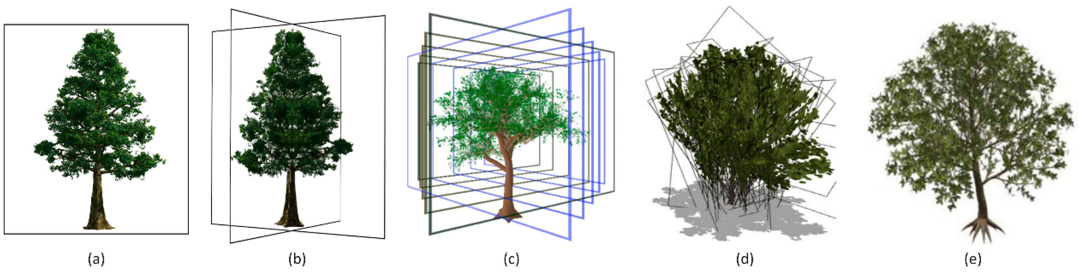
Image-based methods reconstruct an object model based on images, with nearly no need for expertise regarding botany or appropriate rules; these methods have become extremely popular in recent years. These methods obtain 3D feature information and reconstruct the 3D model of the tree by parsing the potential spatial relationship among 2D images. Shlyakter et al. [13] obtained a visual hull produced from photographs to constrain the L-system-based growth mechanism. Han et al. [14] created tree-like objects using only one image, but the types of 3D model that could be obtained were limited. Quan et al. [3] and Tan et al. [5] recovered the camera motion and 3D point clouds for plants using the structure from motion (SFM) approach and built a triangle mesh model of branches and leaves. Ten additional images are required to parse the SFM problem, and this method is typically suitable for small potted plants but not for outdoor trees.
Rule-based methods have been used less frequently in recent years because they require researchers to possess expertise in botany; in contrast, image-based methods have attracted increasing attention because they make it easier to reconstruct real-world trees using 3D models.

1.2. Tree Rendering

The method used to render the primitive of trees has a direct impact on the rendering performance and effect. Rendering methods can be categorized into graphics-based and image-based methods based on the rendering primitive used.

1.2.1. Graphics-Based Methods

Graphics-based methods are generally applicable to objects with a regular geometrical shape that can be further divided into triangles or faces, i.e., graph primitives. Tree models are typically composed of tens of thousands of triangle graphics, which is more than those required for a common object. As illustrated in Figure 1, a sparse tree requires 19,657 triangles to generate the foliage and twigs, which will certainly lower rendering performance and make it difficult to meet the requirements for human-computer interaction. In general, the crown contains the majority of the geometric complexity of a tree and is therefore the key component to address to develop a tree representation that combines a realistic appearance with high-speed rendering.

1.2.2. Image-Based Methods

Image-based rendering (IBR), in which a 3D object is represented using a single or only a few simple geometries that are covered with textures to depict finer details, has been widely used in tree representation.
IBR tree models (IBRTMs) are tree representations with low geometric complexity. For example, the BBTM (Figure 2a), which draws a tree image onto a single billboard and then changes the billboard direction according to the observation direction, is the simplest method with which to represent a tree. The BBTM possesses several significant advantages, such as low geometric complexity, high rendering performance, and feasibility for a large number of trees. However, it also has several unavoidable limitations. The greatest limitation is that it always presents the same appearance of the tree to the viewer, even when the viewpoint is changing. Several other representations have been proposed to eliminate this shortcoming of the BBTM. For example, the CPTM represents a tree using several crossed planes, each of which is mapped to a tree image (Figure 2b). By mapping different images of a tree onto these planes, the CPTM can present different appearances of the tree for varying viewpoints. However, both the BBTM and CPTM still suffer several limitations, such as an unimpressive stereoscopic effect, insufficient lighted effects, and the impression of slicing when viewed from the top side.
IBRTMs can also be used as a simplification of an original detailed tree model. For example, the sparse parts of a tree, i.e., its twigs and leaves, can be alternatively represented by a set of slices (Figure 2c) [15]. Plants can be approximated by dynamically changing sets of billboards, named billboard clouds (Figure 2d) [16]. A hybrid polygon/billboard approach has been proposed to create a simplified tree model that can approximately preserve the visual appearance of the original model but with fewer polygons (Figure 2e) [17]. Using these simplified tree models, although the defects noted above are partially eliminated, the impression of slicing remains.

1.3. Texture Synthesis

In contrast to the BBTM and CPTM, which uses 2D planes as the geometrical base so that texture mapping can be implemented in a direct manner, the SBTM uses 3D irregular curved surfaces as the geometrical base and its texture mapping is more complex. A 2D texture cannot be directly mapped onto a 3D curved surface without stretching or aliasing, so texture synthesis must be used to achieve better texture effects for the SBTM.
In recent decades, texture techniques have undergone rapid development, passing through three stages: texture mapping [18], procedure texture synthesis (PTS) [19,20] and texture synthesis from sample (TSFS) [21,22,23]. TSFS in particular was developed from 2D to 3D to meet more complex requirements. The most outstanding achievement to emerge from such efforts is texture synthesis on surfaces (TSOS). As the earliest example of this technique, Praun et al. [13] proposed a patch-based method that assembles textures on arbitrary surfaces [24,25,26,27,28]. TSOS typically needs to traverse each triangle of the mesh and then assign texture coordinates in the space of the texture sample to the vertices of these triangles. In this process, the texture continuity of adjacent triangular patches must be guaranteed. Because each triangle uses only a part of the sample and no real texture image is generated, the synthesized texture can be called a virtual texture. In this paper, a fast algorithm for texture synthesis that combines texture extension with polygon texture matching is used for the SBTM.
In this paper, the SBTM is proposed to provide a reasonable-looking tree model with reasonable geometric complexity and desirable rendering efficiency. The SBTM uses one or more surfaces to simulate the morphological structure of a tree crown, and further details of the foliage and twigs are represented through texture synthesis. Compared with the BBTM or CPTM, the SBTM provides a more reasonable appearance presenting light and shadow effect which are key elements in creating the sense of volume, even when the viewpoint moves over the top of the tree. Compared with more detailed tree representations, the SBTM achieves a better compromise between realism and efficiency. The SBTM is suitable for tree species that have reasonably sphere-like crowns with few holes throughout their dense canopies, and it is also suitable for representing trees at a medium or high viewing distance in 3D scenes.

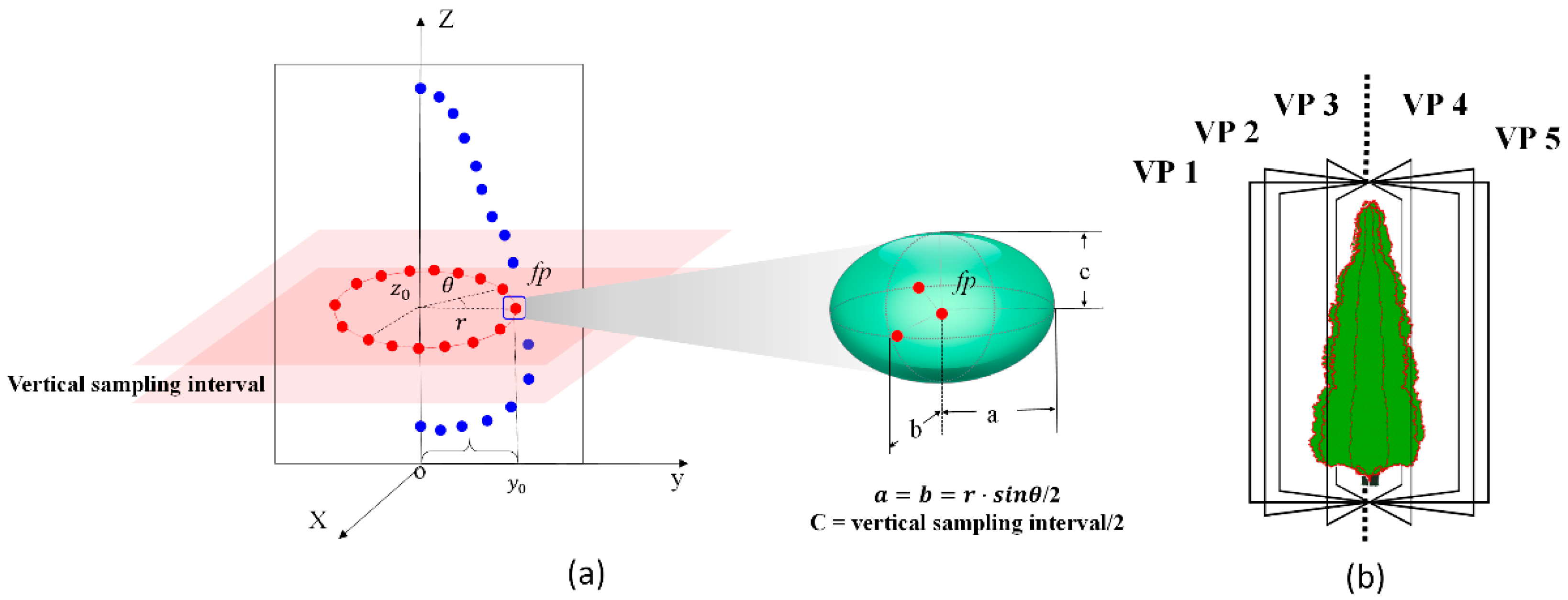
2. Sphere-Board-Based Tree Modeling

2.1. Billboard to Sphere-Board

The basic approach of the BBTM is to map the image of a tree onto a 2D billboard polygon and then adjust the polygon direction according to the observation direction. A ‘sphere-board’, which could be used to present a texture image of tree on the irregular curved surface of a sphere-like object, is proposed to replace the billboard. In this paper, ‘sphere’ is defined as a sphere-like closed irregular surface, so it can be used for representing the crown of many tree species which look like ‘sphere’. The primary difference between a ‘billboard’ and a ‘sphere-board’ is that the former is a 2D plane and the latter is a 3D surface. The geometric similitude between a tree’s crown and a ‘sphere-board’ helps the SBTM to exhibit a more concrete 3D effect and several improved characteristics. The SBTM enables lighted effects because its outline is a solid model. As the viewpoint moves, the part of the crown surface that is facing the observer changes, and the visual appearance can vary accordingly. Even when looking down on the tree model from the top, the observer sees the proper appearance of a tree. This makes the SBTM, based on little geometric complexity, closer to reality than the BBTM or CPTM.
A standard sphere is not identical to a real tree’s crown. If a sphere is to be used to represent a tree crown, the shape of the sphere requires some manner of transformation. A schematic diagram of the crown surface generation technique is provided in Figure 3. Assume that an instrument, which can measure the distance to and record the color of a target point, is moving around a tree at some spatio-temporal interval and that the instrument is always aimed at the geometric center of the tree. As the instrument moves, the line connecting the instrument with the tree center will change, and the intersection point of the line and tree crown will change accordingly. The distance from the instrument to the intersection point and the color of the intersection point can be obtained by the instrument. If these two types of data are collected abundantly and are also evenly distributed over the surface of the crown of a tree, it is possible to reconstruct the crown’s geometric shape and its textural appearance. A reasonable sphere-like surface representing the crown’s shape with a virtual texture can be created using this method, any part of which can provide the viewer with a perspective specific to the appearance of the crown in a given viewing direction. CSG method can also create ‘sphere-like’ crown’s surfaces, but the geometric model is too regular to present irregular crown of trees, and the texture synthesis and mapping are not considered, these are the main differences between the two routes.

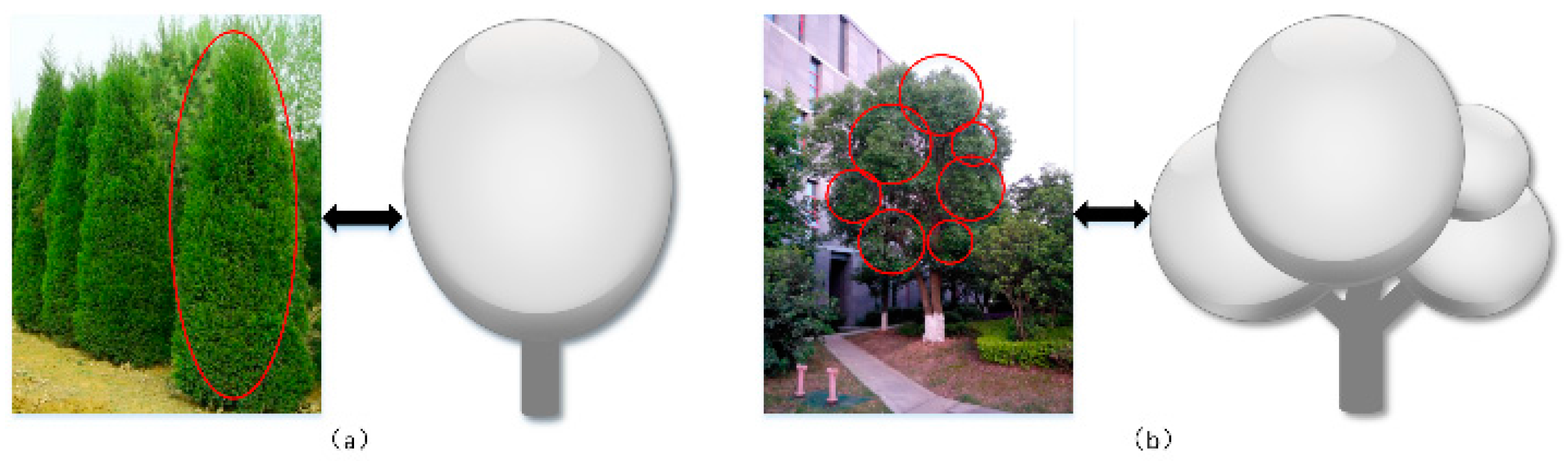
2.2. Applicable Tree Styles

In reality, tree styles vary widely. It is difficult to use a uniform model to represent various types of trees. As a simplified representation of a tree, the SBTM is best suited for trees that have a crown that appears as one or a few clusters of foliage and twigs (CFTs). A CFT is a cluster that combines foliage and twigs; it has a neat outline and no holes and can be approximately represented by a sphere-like curved surface, the appearance of which is visually homogenous. Then, a piece of texture sample can be used to represent the complete appearance of this CFT. The crown of a tree may consist of a single CFT or multiple CFTs (Figure 4a and Figure 4b) and thus can be approximately represented by one or multiple sphere-boards. Certain trees, when viewed at a closer distance, present greater detail and do not look like a CFT. However, when viewed at a distance, their appearance is similar to that of a CFT. In the latter case, the SBTM is still useful.

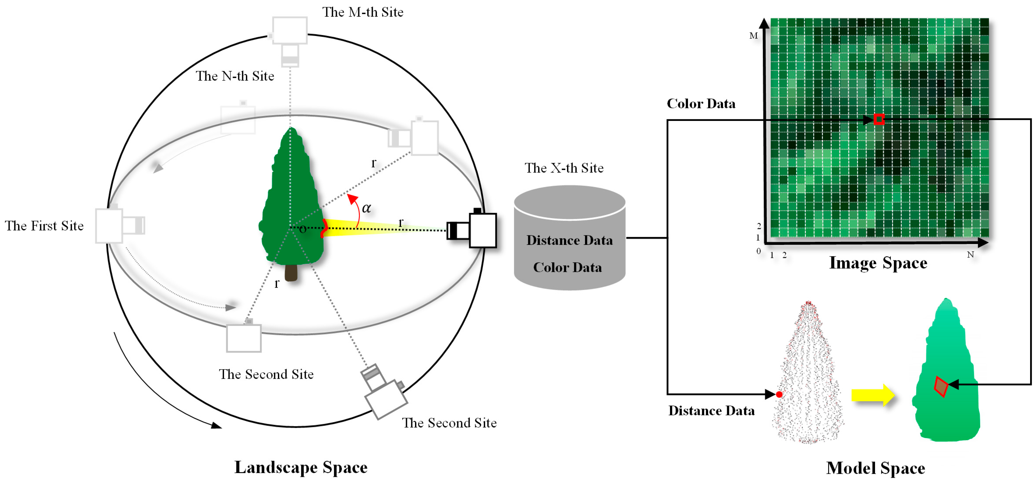
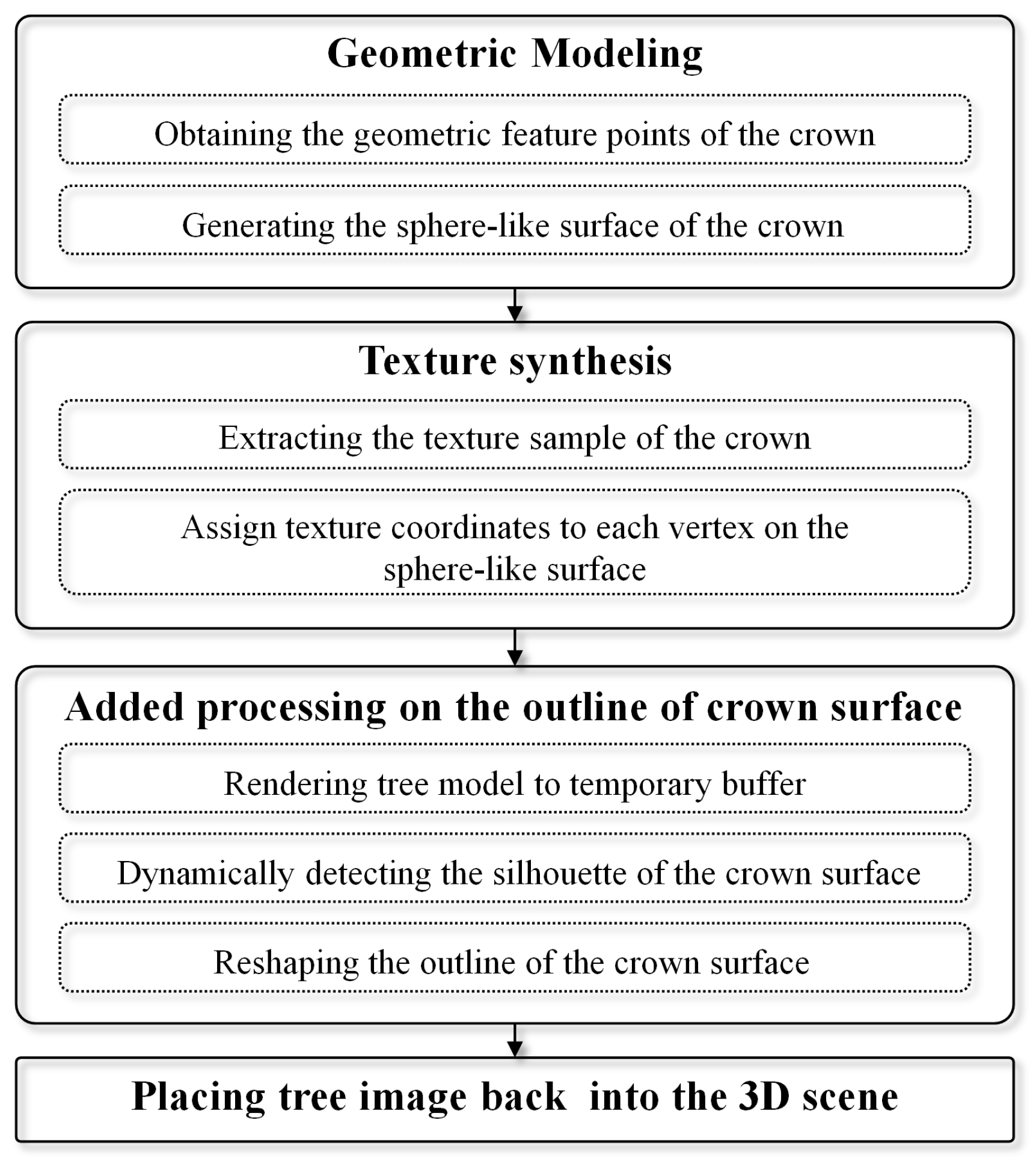
2.3. Process of the Technique

Four steps are performed when using the SBTM (Figure 5): geometric modeling, texture synthesis, additional processing on the crown outline, and integrating the tree image into the frame buffer.
Geometric modeling generates a sphere-like surface to approximate the shape of the CFT. The simplest geometric modeling approach is to randomly transform a standard sphere to represent a CFT, but the effects of this approach are limited. The costliest method is to acquire point cloud data using a laser scanner and then filter out the useful points to construct the sphere-like surface to represent the CFT. For a real tree, images taken from surrounding viewpoints at the same distance can be used to generate a surface as an approximation of the CFT (as illustrated in Section 3.1).
After geometric modeling, a virtual texture is used to delineate the appearance of the tree crown. Ideally, this texture should be continuously distributed over the sphere-like surface without aliasing. However, a normal 2D image cannot meet these expectations because it is suitable only for presentation on a 2D plane. Instead, the texture synthesis technique must be used to generate the expected virtual texture based on a sample of the desired texture that is both small and fully representative (as illustrated in Section 3.2).
Based on a geometric sphere-like surface and a synthesized texture, the rendered image of a tree can be completed. In such an image, the inside of the crown, which is depicted by a virtual texture, looks realistic and natural, but the profile edge of the crown, which is simply the map of the outline of a sphere-like surface, looks like an artificial trimmed edge and is overly smooth and continuous. By contrast, when an observer views a real CFT, its profile edge exhibits an intense irregularity. We therefore must process the outline of the crown surface to make it look more irregular and thus more natural (as illustrated in Section 3.3).
The last step is to integrate the processed tree image back into the 3D scene. When rendering a tree model into a temporary color buffer, the depth value should be simultaneously recorded into a corresponding temporary depth buffer. Then, the frame buffer of the 3D scene should be updated by replacing the pixels in the frame buffer that have greater depth value than their corresponding pixels in the temporary color buffer of the tree model, which means that some portion of the frame buffer must be replaced by the rendered tree image (as illustrated in Section 3.4).

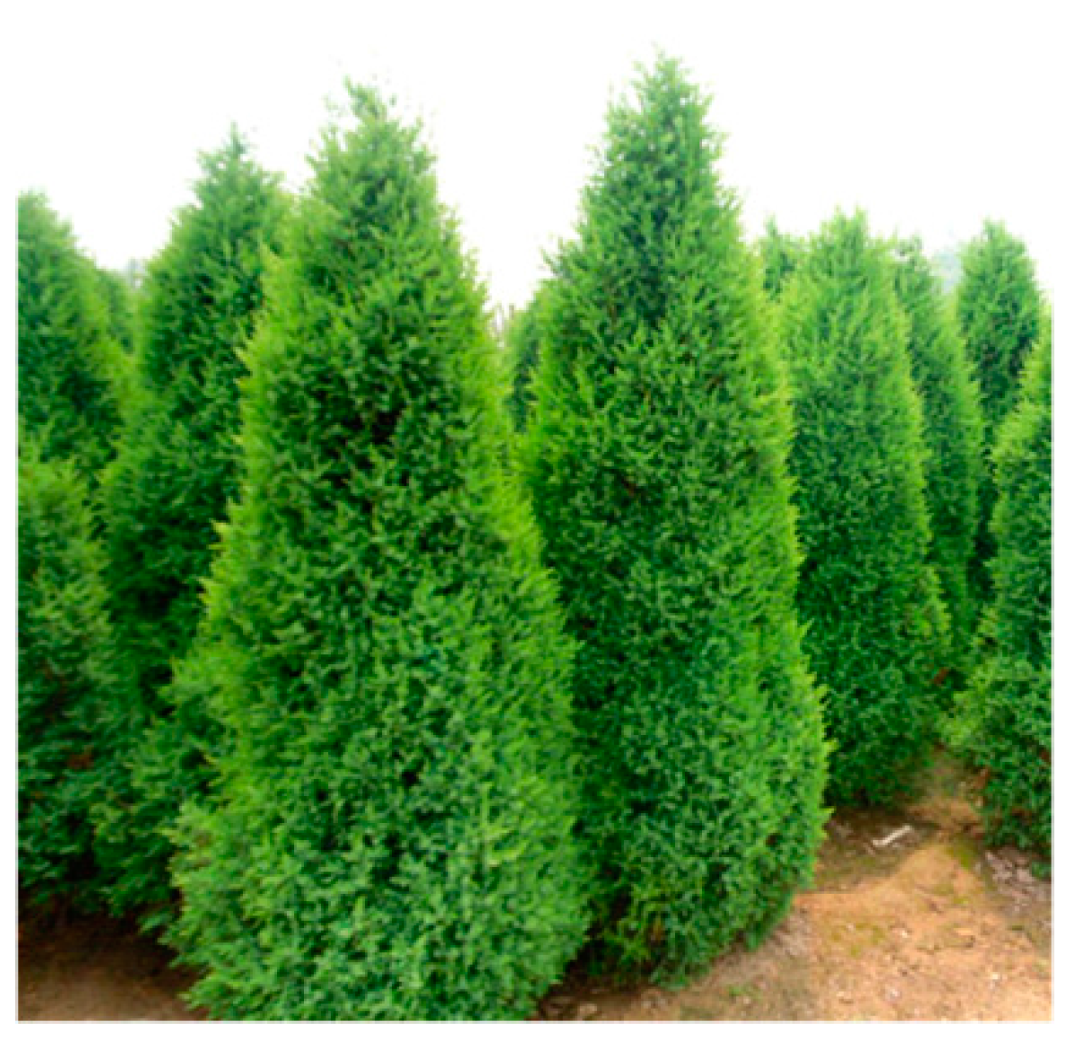
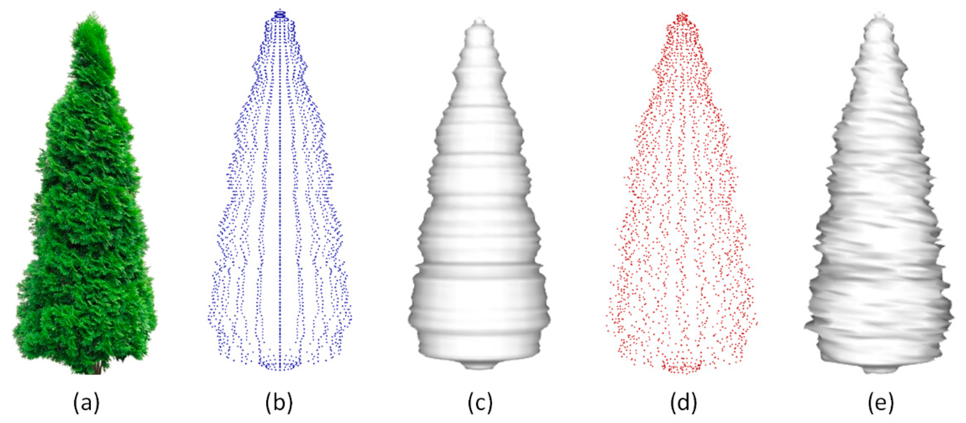
3. Case Study of Sabina Chinensis

Sabina chinensis is a species of coniferous evergreen shrub. Mature trees typically continue to bear some juvenile foliage as well as adult foliage. The young branches of Sabina chinensis stretch upward, forming a spire-like shape. The older and lower limbs spread and flatten to form a circular canopy (Figure 6). Sabina chinensis is a typical CFP case and was thus chosen for illustration in this paper.

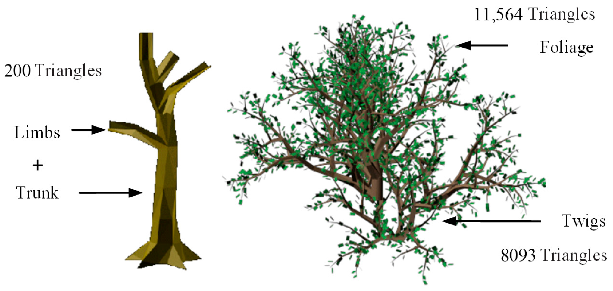
3.1. Geometric Modeling

There are many ways to create a sphere-like surface to represent a tree crown, one of which is based on tree images. Input images typically contain background objects and the first step is to separate the tree from its background. Various solutions can be used to segment an image, ranging from thresholding [29], region growing [30] to clustering method [31]. The segmentation results may differ if using different methods. And the complexity of background also has a great effect on the results. In this paper, a thresholding method is used to extract tree foreground based on colors of pixels. Firstly, the color of each pixel is converted from RGB to HSV color space, where H means hue. The value of H is between 0–360°. Usually, the color of tree’s crown is green and its H value is between 90–150°. It can be used to extract the region of crown and the extracted result is shown in Figure 7b. Some small noise regions of green color are also extracted. A morphological opening is applied to Figure 7b to remove such unexpected small regions. There may be some unexpected holes in the extracted tree crown, which may be caused by dark shadow or sparse region. A morphological closing is applied to Figure 7c to fill these holes (Figure 7d). Then the outline of crown can be obtained by edge detection (Figure 7e). For the image of overlapped trees or confusing boundary between foreground and background, the satisfied segmentation becomes a challenge. In the latter case, manual interventions are needed to adjust the segmentation results better. While using proposed method, choosing an appropriate tree image is very important.
The significant turning pixels located in the silhouette of the crown are chosen as feature points. If only one image can be used as input, the acquired feature points on the profile line can be copied and moved around the tree stem (Z axis). This process can be repeated many times to form a 3D point cloud (Figure 8a). Subsequently, the positions of the generated feature points should be randomly redistributed within a constrained range defined by an ellipsoid, named the ellipsoid for disturbing feature points (EDFP) (Figure 8a). If multiple images can be used as input then abundant feature points can be acquired from the geometric outlines of different profiles of the tree crown (Figure 8b). Even in the latter case, random disturbance of the feature points is still necessary if they are distributed too evenly. The final step is to generate a sphere-like surface (Figure 9c and Figure 9e) based on the 3D feature point cloud (Figure 9b and Figure 9d). The optimized shape of the sphere-like surface presents an irregular effect at the microscopic level.

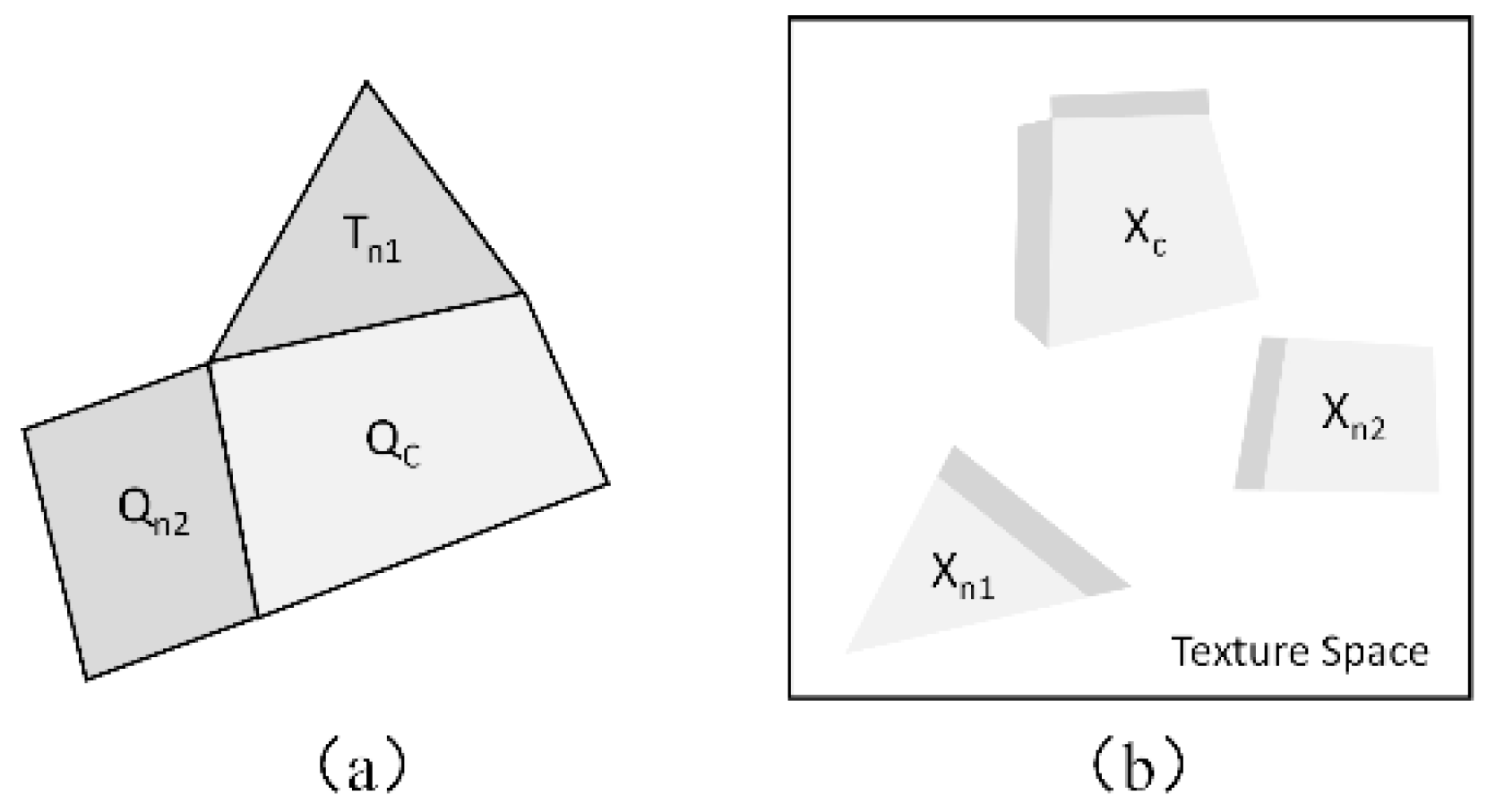
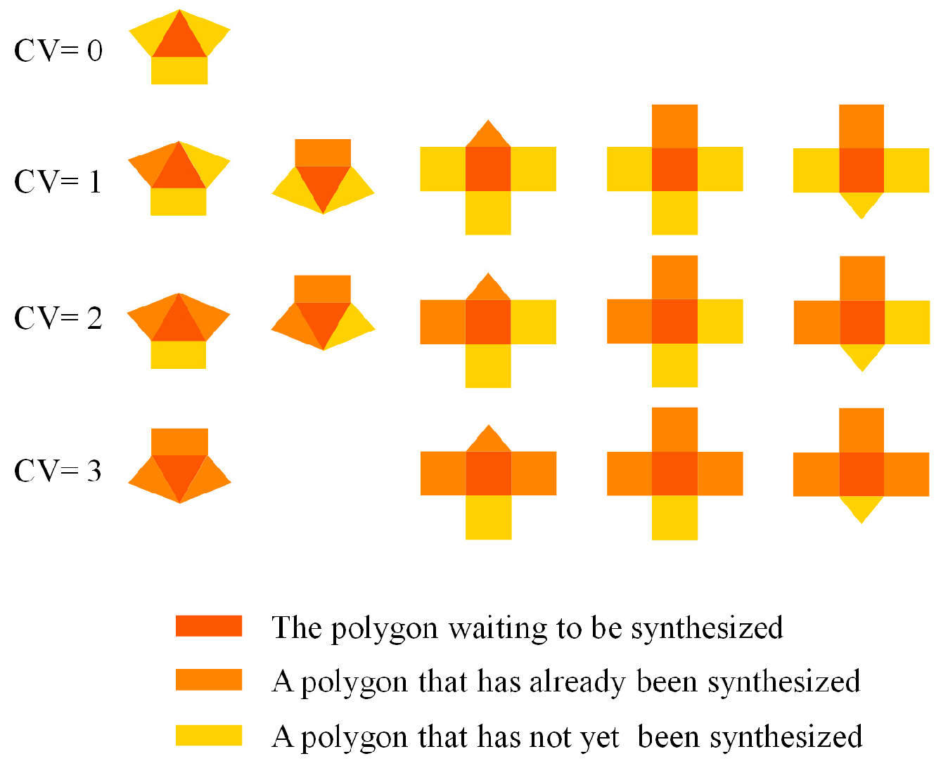
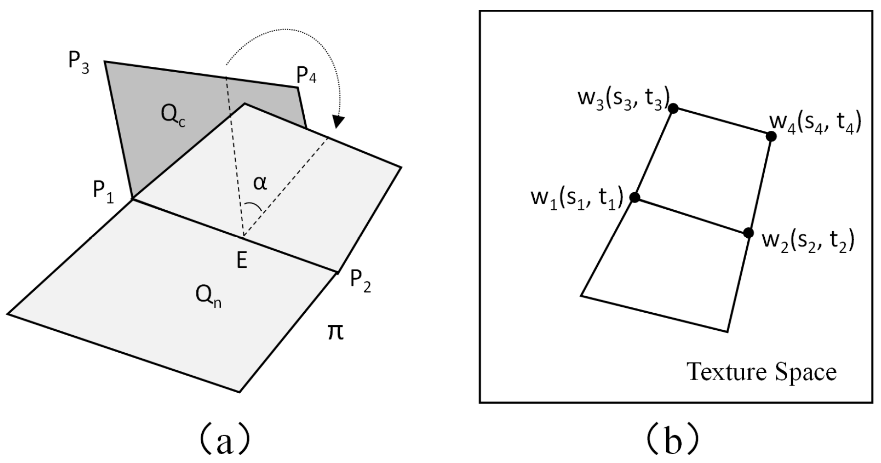
3.2. Texture Synthesis

In the texture synthesis process, a method that combines texture extension with polygon texture matching, is used to assign texture coordinates to each vertex on the sphere-like surface. The polygons include triangles and quadrilaterals, both of which are used to construct the surface with the intent of eliminating redundant vertices and reducing the number of rendering primitives. For a polygon waiting to be synthesized, the constraint value (CV) is defined as the number of synthesized polygons adjacent to it. The use of triangles and quadrilaterals together results in more possible CV scenarios (Figure 10).
The process of calculating the texture coordinates varies for different CVs. If the CV of a polygon being synthesized is 1, the process can be performed by extending the texture coordinates of its neighbor polygon. During this process, some geometric transformations and mathematical calculations must be performed for texture extension. First, the polygon being synthesized should be rotated around an axis, i.e., the shared edge between the polygon and its synthesized neighbor, such that it shares a plane with its synthesized neighbor (Figure 11a). Second, the texture coordinates of the polygon being synthesized should be calculated based on the geometrical relationship between it and its synthesized neighbor, both of which are now on the shared plane and the latter of which has texture coordinates that have already been determined (Figure 11b). If the CV of the polygon being synthesized is greater than 1 then the calculation of its texture coordinates can be performed by matching its border with those of its neighbors based on their largest similarity value, as illustrated in Figure 12. Once the texture coordinates of all polygons’ vertices have been determined, the visual seams generated between adjacent pixel blocks must be eliminated.

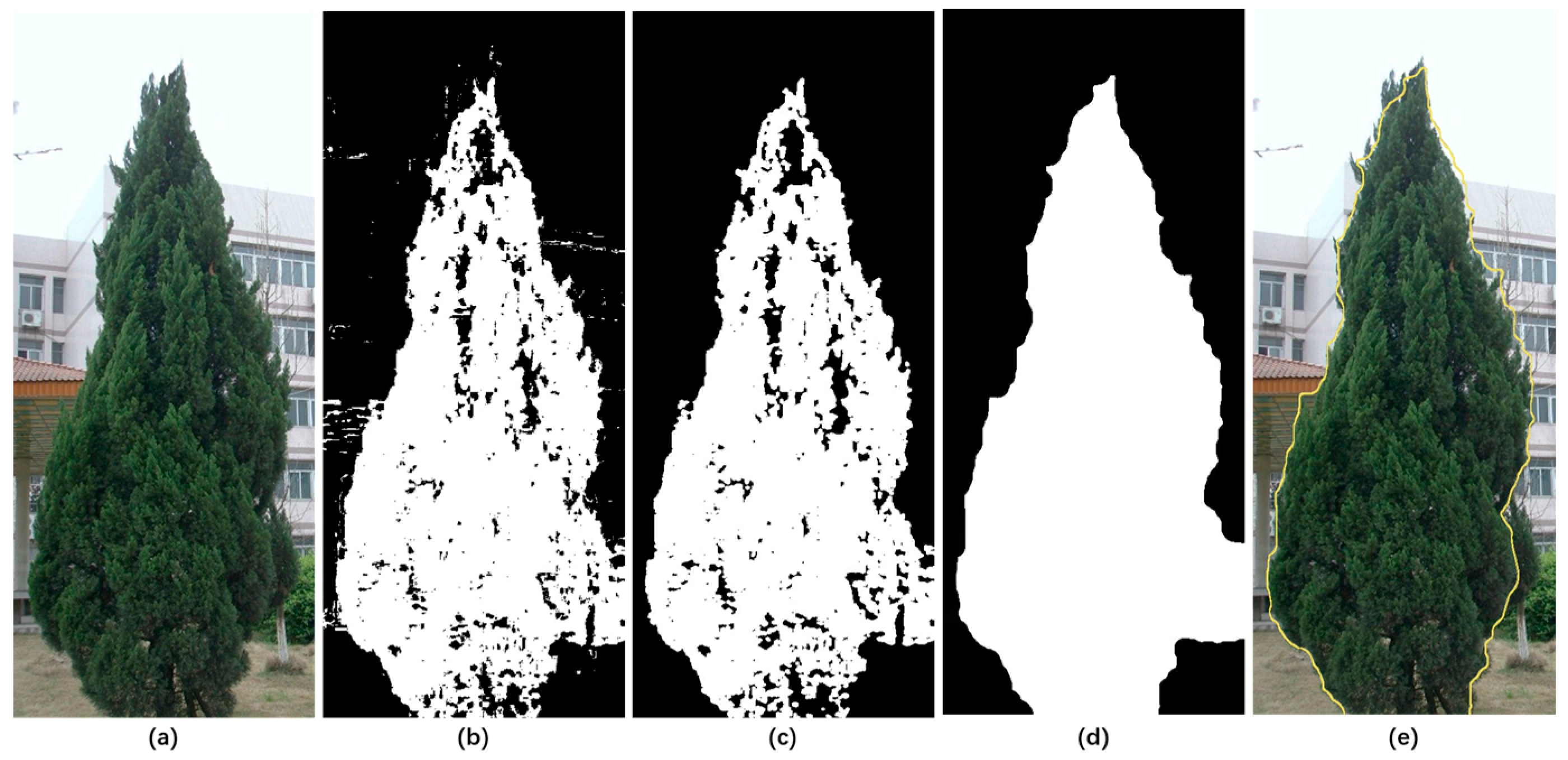
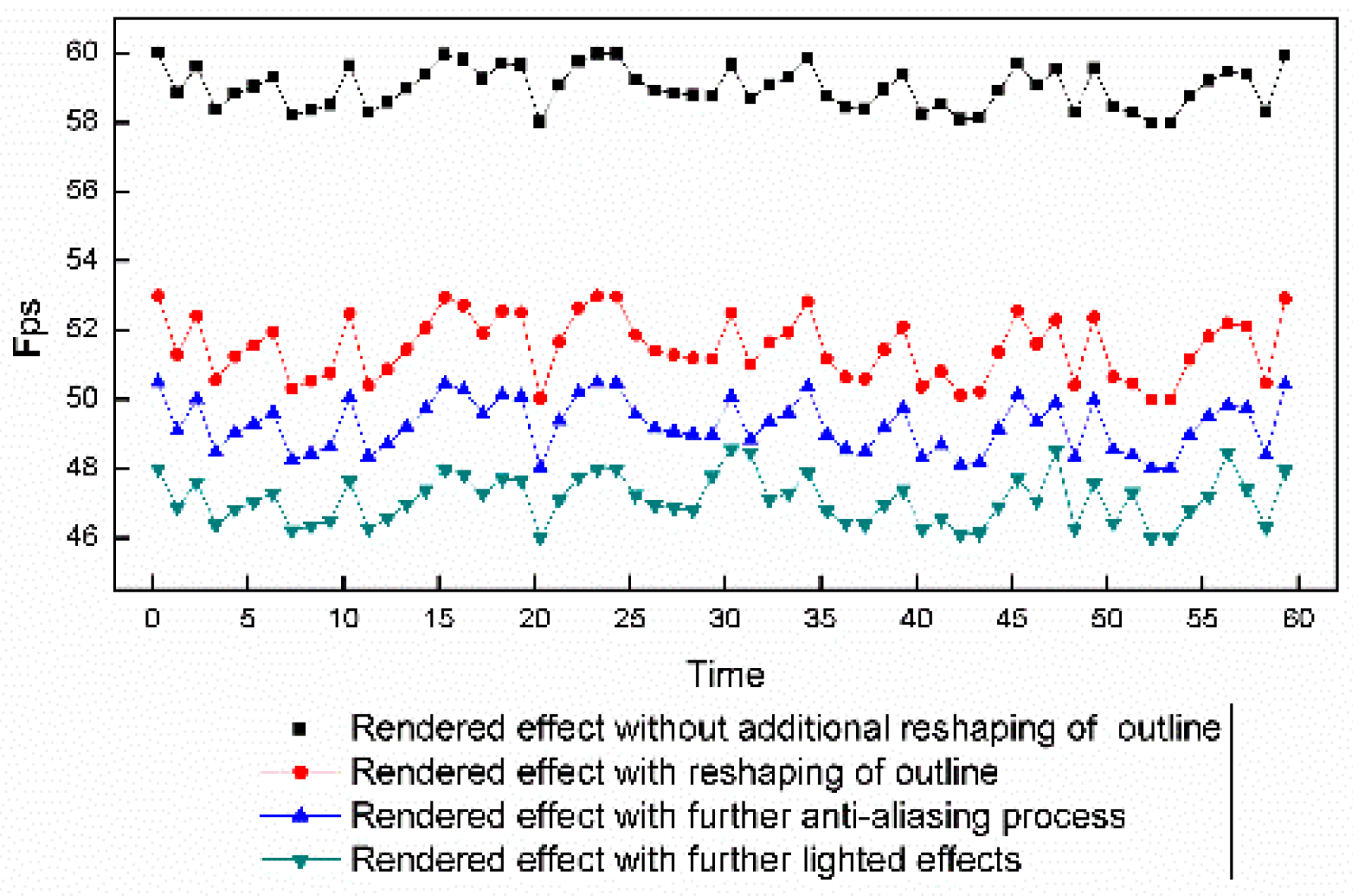
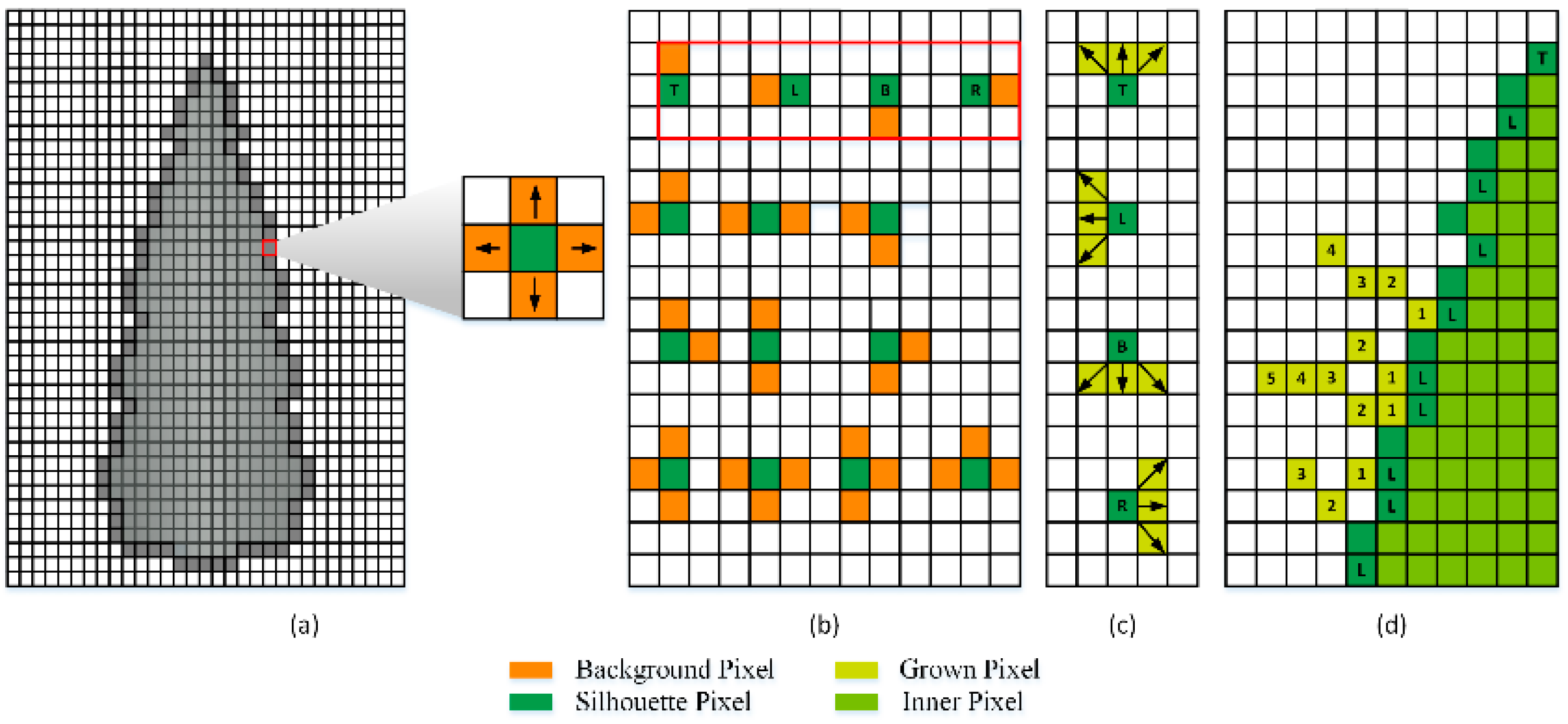
3.3. Reshaping of the Crown Surface Outline

The crown surface outline must be reshaped after tree rendering to enhance its irregularity and give the crown a more realistic appearance. It is difficult to propose a universal method to reshape the outlines of the crown surfaces of various trees. For the example tree Sabina chinensis, we choose to simulate the growth of several pixels located on the silhouette of its crown.
  • Silhouette pixels: When rendering a tree into a temporary buffer, the resulting depth value of the tree area is distinctly different from that of the background area, which can assist in determining the tree area. For each pixel in the tree area, if it has one or more neighboring background pixels, the pixel is considered to be a silhouette pixel (Figure 13a).
  • Root pixels: The silhouette pixels with only one neighboring background pixel (marked with a red box in Figure 13b) are selected as root pixels, which are made to grow randomly to simulate the irregularity and burr effects of the tree crown.
  • Grown pixels: The new pixels grown from the root pixels are defined as grown pixels. They are described by a 3D vector (direction, color, depth). The growth direction is randomly copied from one of three predefined values (Figure 13c). The grown pixels share the color and depth value of their root pixels.
  • Growth length: The total accumulated quantity of grown pixels is termed the growth length (GL), which is limited to lie within a predefined range (Qmin, Qmax) (Figure 13d). The limitation range varies dynamically based on the depth value of the root pixel, i.e., the growth limitations may be different for root pixels located at different distances.

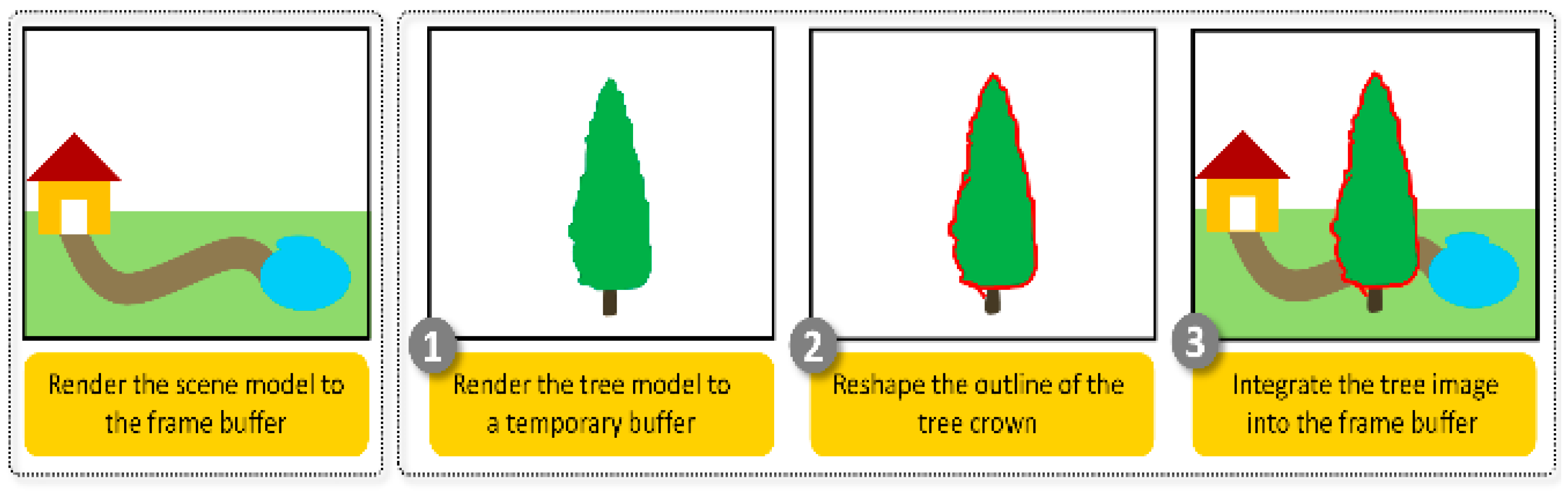
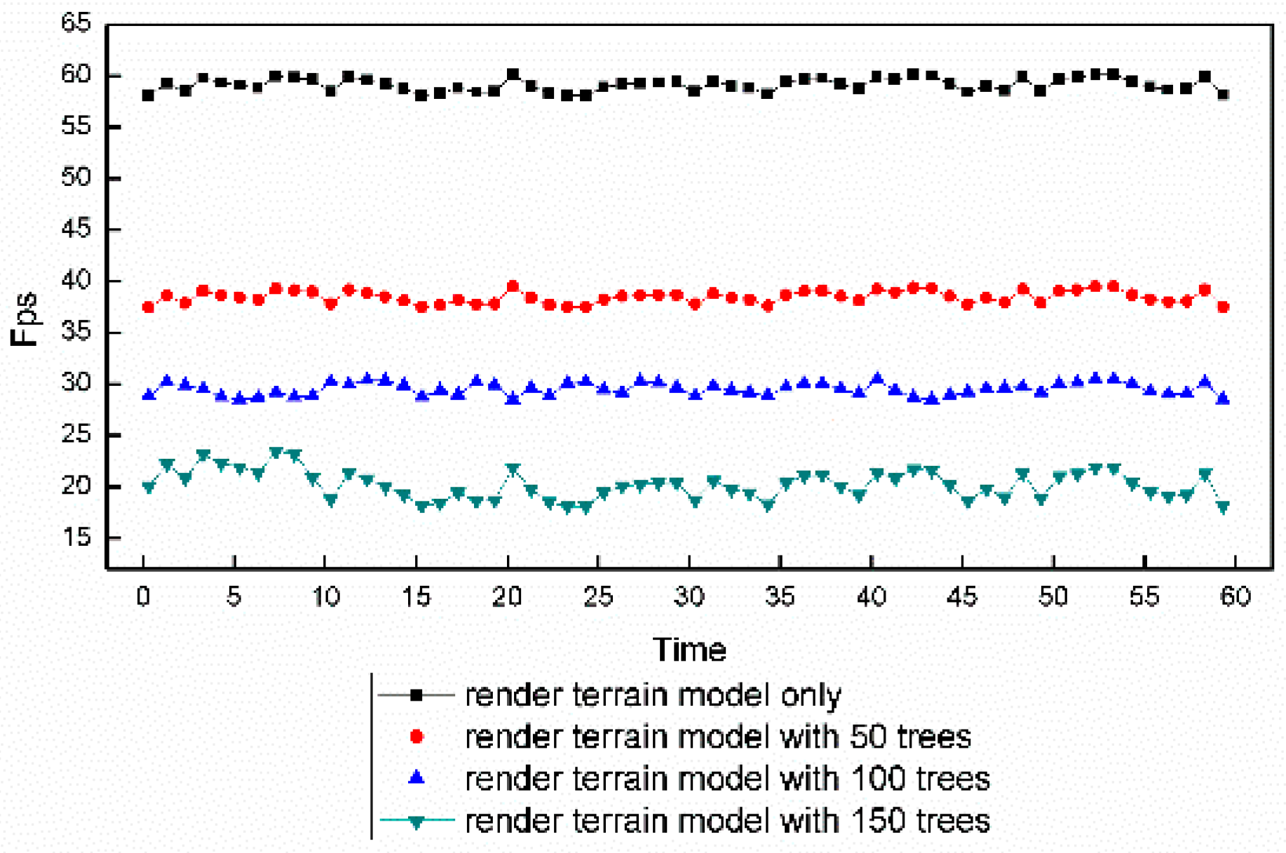
3.4. Integration of the Rendering Results

After the rendered tree image is reshaped, the next step is to place it back into the 3D scene. As illustrated in Figure 14, this process is simple. For each pixel in the tree image, its depth value is compared with that of the corresponding pixel in the frame buffer; the frame pixel must be replaced with a tree pixel if the depth value of the corresponding tree pixel is less than that of the frame pixel.

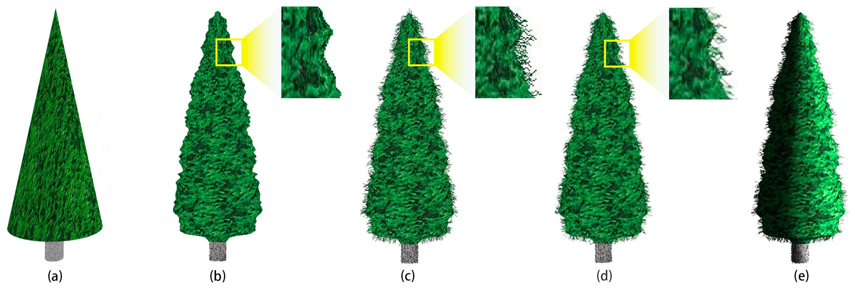
3.5. Final 3D Effects

The performance of our method which is implemented based on OpenSceneGraph 3.4.0 (an open source 3D graphics application programming interface) is tested on a 2.3 GHz Intel Xeon, with 16 GB RAM, and an NVIDIA Quadro K4000 with 2 GB. The comparison between the final 3D effects for Sabina chinensis generated by CSG method and our method is shown in Figure 15. CSG method combines basic regular geometries to construct complex tree models. As to sabina chinensis, a cone and a cylinder represents the crown and trunk of a tree respectively in Figure 15a. CSG method can even make much complicated model than Sabina chinensis (Figure 4b), but the surface of the generated model will be too regular to present the irregular shape of crowns with realistic illumination, if the disturbance of vertices is not applied to. In addition, the texture distortion is obvious at abruptly changing parts. The proposed method, which constructs crown surfaces from feature points of extracted outlines, is more direct and can achieve more realistic results.
Compared with a real tree, the outline of rendered tree by our method presents too smooth and then looks unnatural (Figure 15b). The reshaping of crown outline makes it more burred and realistic (Figure 15c). However, when the tree is observed closely, the aliasing will occur as shown in the magnified part of Figure 15c. After anti-aliasing has been applied, the mosaic disappears, and the effect looks more natural (Figure 15d). Furthermore, better lighted effects can easily be applied to the proposed tree model (Figure 15e).
The data on the numbers of primitives for the two different tree models are shown in Table 1 for comparison. Compared with the tree model presented in Figure 1, the number of primitives in the sphere-board-based model is greatly decreased, thus considerably improving the rendering performance. Compared with the BBTM and CPTM, the SBTM has more geometric complexity, and the outline reshaping process requires slightly more system resources (Figure 16). SBTM sacrifices the performance in exchange for much better 3D visual effects. And the frame rate for the SBTM, even with lighted effects, still remains at an acceptable level of between 45 and 48.
To facilitate the comparison of visual differences, trees constructed using either the CPTM or the SBTM were both placed in a 3D scene (Figure 17). When observed at a closer distance, the SBTM presents illumination and shadow on its surface and provides a stronger and better 3D visual effect. When viewed from the sky, i.e., from above of the trees, the SBTM still maintains a reasonable 3D effect, whereas the CPTM does not. In addition, the SBTM can support lighted effects, whereas the CPTM cannot.
To comprehensively examine the effects and performance of the model, a simple grove composed of hundreds of Sabina chinensis trees was constructed by copying, scaling, and then randomly placing one of several pre-constructed tree models covered with different virtual textures. With an increase in the number of trees, the frame rate tended to decline (Figure 18). When the number of the trees was increased to 150, the frame rate remained at approximately 20fps. In general, reshaping of the crown surface outline for each tree is not necessary, especially for those trees in the distance. For example, for a grove scene (Figure 19a) consisting of a terrain model with 31,832 triangles and 540 tree models, approximately 140 of the tree models were reshaped, and the frame rate remained at 22 fps.

4. Discussion and Conclusions

In this paper, the SBTM is proposed as a simplified tree representation with a better compromise between realism and efficiency. Drawing on the advantages of IBR, the SBTM focuses on simulating the morphological structure of a tree’s crown using the simplest possible geometry while presenting greater details of the foliage and twigs using virtual textures. Compared with the BBTM and CPTM, the SBTM has greater geometric complexity because it uses one or more sphere-like surfaces to represent the crown of a tree; however, its performance is minimally affected by the additional geometric complexity. The SBTM eliminates the defects suffered by the BBTM or CPTM, such as their unimpressive stereoscopic effect and insufficient lighted effects as well as the impression of slicing that they give when viewed from the top. The SBTM presents better 3D effects to the viewer, such as a viewpoint-dependent appearance and realistic lighted effects. In addition, although the SBTM is a simple model, it enables the generation of animation through control of the movements of feature points because of its geometric characteristics, which deserve further exploration.
The detailed procedure for using the SBTM is also introduced, including geometric modeling, texture synthesis, reshaping of the crown outline, and finally integrating the results into a 3D scene. For many tree species, both the image texture and geometric outline of the crown contain significant detail, and the crowns of different species may thus exhibit large differences when observed from a close distance. Therefore, during the steps of the SBTM, the methods for synthesizing the virtual textures and reshaping the crown outline may differ for different tree species; this topic also deserves further exploration. For the purposes of illustration, the tree species Sabina chinensis is a relatively simple example. Other tree species may have greater complexity, resulting in additional challenges regarding the use of the SBTM. However, when observed at a medium or longer distance, a tree of any species will exhibit high textural similarity over different parts of its crown, one or more sphere-like geometrical outlines, and a narrow hazy border. For such trees in a 3D scene, the SBTM is an effective method of representation. In fact, the proposed method is not applicable to all tree species, especially for sparse trees which have little textural similarity and are hard to be approximated as solid geometries. And the modeling of crowns with holes is still under study. For trees with multiple sphere-like crowns, our method has some limitations in constructing irregular surfaces and further exploration can be done by using CSG method. Both the specific method for reshaping the crown surface outline of Sabina chinensis and the process of integrating the result into a 3D scene are implemented based on the pixel calculation of the device screen, which consumes some system resources and should be further optimized.
The SBTM has been preliminarily investigated, and the model for a single CFT has been introduced in detail. However, for the case of multiple CFTs with more irregular morphological structures and more diverse textural appearances, further studies must be conducted. Challenges that remain to be addressed include how to represent the transition effect between adjacent CFTs and how to detect and then reshape the silhouettes of sphere-like surfaces inside the crown of a tree with multiple CFTs.

Acknowledgments

This study was supported by the National Natural Science Foundation of China (Grant No. 41371365) and the Key Project of the National Natural Science Foundation of China (Grant No. 41230751). In addition, the authors thank the Zhenjiang Institute of Surveying and Mapping, Jiangsu Province, China, for providing the 3D terrain model.

Author Contributions

Jiangfeng She and Xingchen Guo conceived the Sphere-board-based Tree Modeling method and wrote the paper; Xingchen Guo and Xin Tan implemented the method and performed the experiments; Jianlong Liu processed the scene model data and analyzed the experiments data.

Conflicts of Interest

The authors declare no conflict of interest.

References

  1. Gardner, G.Y. Simulation of natural scenes using textured quadric surfaces. In Proceedings of the SIGGRAPH ’84 Conf Proc (11th Annu Conf on Comput Graph and Interact Tech), Minneapolis, MN, USA, 23–27 July 1984; ACM: New York, NY, USA, 1984; Volume 18, pp. 11–20. [Google Scholar]
  2. Boudon, F.; Meyer, A.; Godin, C. Survey on Computer Representations of Trees for Realistic and Efficient Rendering; Research Report; CNRS: Paris, France, 2006; Available online: https://hal.inria.fr/hal-00830069/ (accessed on 29 January 2018).
  3. Quan, L.; Tan, P.; Zeng, G.; Yuan, L.; Wang, J.; Kang, S.B. Image-based plant modeling. In Proceedings of SIGGRAPH ‘06 Special Interest Group on Computer Graphics and Interactive Techniques Conference, Boston, MA, USA, 30 July–3 August 2006; ACM: New York, NY, USA, 2006; Volume 25, pp. 599–604. [Google Scholar]
  4. Shlyakhter, I.; Rozenoer, M.; Dorsey, J.; Teller, S. Reconstructing 3D tree models from instrumented photographs. IEEE Comput. Graph. Appl. 2001, 21, 53–61. [Google Scholar] [CrossRef]
  5. Tan, P.; Zeng, G.; Wang, J.; Kang, S.B.; Quan, L. Image-based tree modeling. ACM Trans. Graph. 2007, 26, 87. [Google Scholar] [CrossRef]
  6. Mantler, S.; Tobler, R.F.; Fuhrmann, A.L. The State of the Art in Realtime Rendering of Vegetation; VRVis Certer for Virtual Reality and Visualization: Vienna, Austria, 2003. [Google Scholar]
  7. Prusinkiewicz, P.; James, M.; Měch, R. Synthetic topiary. In Proceedings of the 21st Annual Conference on Computer Graphics and Interactive Techniques, Orlando, FL, USA, 24–29 July 1994; pp. 351–358. [Google Scholar]
  8. Weber, J.; Penn, J. Creation and rendering of realistic trees. In Proceedings of the 22nd Annual Conference on Computer Graphics and Interactive Techniques, Los Angeles, CA, USA, 6–11 August 1995; pp. 119–128. [Google Scholar]
  9. De Reffye, P.; Edelin, C.; Francon, J.; Jaeger, M.; Puech, C. Plant models faithful to botanical structure and development. Comput. Graph. 1988, 22, 151–158. [Google Scholar] [CrossRef]
  10. Bloomenthal, J.; Bajaj, C. (Eds.) Introduction to Implicit Surfaces; Morgan Kaufmann: Burlington, MA, USA, 1997; pp. 178–180. [Google Scholar]
  11. Deussen, O.; Lintermann, B. Digital Design of Nature: Computer Generated Plants and Organics; Springer Science & Business Media: Berlin, Germany, 2006; pp. 84–86. [Google Scholar]
  12. Wei, L.Y.; Levoy, M. Texture synthesis over arbitrary manifold surfaces. In Proceedings of the 28th Annual Conference on Computer Graphics and Interactive Techniques, Los Angeles, CA, USA, 12–17 August 2001; pp. 355–360. [Google Scholar]
  13. Praun, E.; Finkelstein, A.; Hoppe, H. Lapped textures. In Proceedings of the 27th Annual Conference on Computer Graphics and Interactive Techniques, New Orleans, LA, USA, 23–28 July 2000; pp. 465–470. [Google Scholar]
  14. Han, F.; Zhu, S.C. Bayesian reconstruction of 3d shapes and scenes from a single image. In Proceedings of the First IEEE International Workshop on Higher-Level Knowledge in 3D Modeling and Motion Analysis, HLK 2003, Nice, France, 17 October 2003; pp. 12–20. [Google Scholar]
  15. Jakulin, A. Interactive vegetation rendering with slicing and blending. In Proceedings of the Eurographics, Short Presentations, Norrköping, Sweden, 3–7 May 2000. [Google Scholar]
  16. Behrendt, S.; Colditz, C.; Franzke, O.; Kopf, J.; Deussen, O. Realistic real-time rendering of landscapes using billboard clouds. Comput. Graph. Forum 2005, 24, 507–516. [Google Scholar] [CrossRef]
  17. Lee, J.; Kuo, C.C.J. Tree model simplification with hybrid polygon/billboard approach and human-centered quality evaluation. In Proceedings of the 2010 IEEE International Conference on Multimedia and Expo (ICME), Suntec City, Singapore, 19–23 July 2010; pp. 932–937. [Google Scholar]
  18. Catmull, E. A Subdivision Algorithm for Computer Display of Curved Surfaces. Ph.D. Thesis, University of Utah, Salt Lake City, UT, USA, 1974. [Google Scholar]
  19. Perlin, K. An image synthesizer. ACM SIGGRAPH Comput. Graph. 1985, 19, 287–296. [Google Scholar] [CrossRef]
  20. Peachey, D.R. Solid texturing of complex surfaces. ACM SIGGRAPH Comput. Graph. 1985, 19, 279–286. [Google Scholar] [CrossRef]
  21. Efros, A.; Leung, T.K. Texture synthesis by non-parametric sampling. In Proceedings of the Seventh IEEE International Conference on Computer Vision, Kerkyra, Greece, 20–27 September 1999; pp. 1033–1038. [Google Scholar]
  22. Portilla, J.; Simoncelli, E.P. A parametric texture model based on joint statistics of complex wavelet coefficients. Int. J. Comput. Vis. 2000, 40, 49–70. [Google Scholar] [CrossRef]
  23. Wei, L.Y.; Levoy, M. Fast texture synthesis using tree-structured vector quantization. In Proceedings of the 27th Annual Conference on Computer Graphics and Interactive Techniques, New Orleans, LA, USA, 23–28 July 2000; pp. 479–488. [Google Scholar]
  24. Magda, S.; Kriegman, D. Fast texture synthesis on arbitrary meshes. In Proceedings of the 14th Eurographics Workshop on Rendering, Leuven, Belgium, 25–27 June 2003; pp. 82–89. [Google Scholar]
  25. Soler, C.; Cani, M.P.; Angelidis, A. Hierarchical pattern mapping. ACM Trans. Graph. 2002, 2, 673–680. [Google Scholar]
  26. Turk, G. Texture synthesis on surfaces. In Proceedings of the 28th Annual Conference on Computer Graphics and Interactive Techniques, Los Angeles, CA, USA, 12–17 August 2001; pp. 347–354. [Google Scholar]
  27. Wu, F.L.; Mei, C.H.; Shi, J.Y. Method of direct texture synthesis on arbitrary surfaces. J. Comput. Sci. Technol. 2004, 19, 643–649. [Google Scholar] [CrossRef]
  28. Xue, F.; Zhang, Y.; Jiang, J.; Hu, M.; Jiang, T. Fast texture synthesis on arbitrary surfaces using texture extension and triangular texture matching. J. Comput. Aided Des. Comput. Graph. 2007, 19, 221–226. [Google Scholar]
  29. Al-Amri, S.S.; Kalyankar, N.V. Image segmentation by using threshold techniques. arXiv, 2010; arXiv:1005.4020. [Google Scholar]
  30. Tremeau, A.; Borel, N. A region growing and merging algorithm to color segmentation. Pattern Recognit. 1997, 30, 1191–1203. [Google Scholar] [CrossRef]
  31. Barghout, L.; Sheynin, J. Real-world scene perception and perceptual organization: Lessons from Computer Vision. J. Vis. 2013, 13, 709. [Google Scholar] [CrossRef]
Figure 1. Graphics-based method (200 triangles for the solid part, i.e., trunk and limbs, and 19,657 triangles for the sparse part, i.e., foliage and twigs, by Jakulin [15]).
Ijgi 07 00045 g001
Figure 2. Different cases of billboard-based tree models (IBRTMs): (a) a billboard-based tree model; (b) a crossed-plane-based tree model; (c) the sparse part of a tree approximated by a set of slices (by Jakulin [15]); (d) a tree model simplified as a billboard cloud (by Behrendt et al. [16]); (e) a simplified tree model based on a hybrid polygon/billboard method (by Lee and Kuo [17]).
Ijgi 07 00045 g002
Figure 3. Schematic diagram of crown surface generation.
Ijgi 07 00045 g003
Figure 4. Two different tree styles and the corresponding conceptual models based on the sphere-board approach: (a) the crown is a single cluster of foliage and twigs (CFT) and can be represented by one sphere-like surface; (b) the crown is composed of multiple CFTs and can be represented by multiple sphere-like surfaces.
Ijgi 07 00045 g004
Figure 5. Process of the technique.
Ijgi 07 00045 g005
Figure 6. Sabina chinensis.
Ijgi 07 00045 g006
Figure 7. The segmentation of tree from background: (a) original image; (b) the extracted region by H value (between 90–150°); (c) the result of morphological opening to (b); (d) the result of morphological closing to (c); (e) the outline of segmented tree.
Ijgi 07 00045 g007
Figure 8. Creating a sphere-like surface to represent a tree crown: (a) rotating and disturbing the feature points of the tree profile acquired from a single tree image, blue points denote feature points extracted from silhouette and red points denote the points created by rotation from one feature point; (b) geometric outlines of the tree crown created from multiple images taken from different viewpoints.
Ijgi 07 00045 g008
Figure 9. Intermediate results of geometric modeling: (a) an image of the crown serving as the sole information source for both geometric modeling and texture synthesis; (b) a 3D point cloud formed by copying and then rotating the feature points acquired on the profile line; (c) a geometric surface generated based on the original 3D point cloud; (d) the disturbed point cloud; (e) a geometric surface generated based on the disturbed 3D point cloud.
Ijgi 07 00045 g009
Figure 10. Possible configurations for different constraint values (CVs).
Ijgi 07 00045 g010
Figure 11. Texture extension (CV = 1): (a) Qc is a polygon waiting to be synthesized and has one synthesized neighbor (Qn). Qc is rotated around the shared edge (P1 P2) to place it on the same plane as Qn. (b) In the space of the texture sample, wi is the mapped point of Pi and (si, ti) is the corresponding texture coordinate of Pi. The texture coordinates of P3 and P4 can be deduced from the known texture coordinates of P1 and P2 based on the geometric relationship between the rotated Qc and Qn.
Ijgi 07 00045 g011
Figure 12. Texture matching (CV > 1): (a) Qc is a polygon waiting to be synthesized and has two synthesized neighbors (Tn1 and Qn2). (b) In the texture space, Xn1 and Xn2 are the pixel blocks used to texture Tn1 and Qn2, respectively. Some pixel block Xc, two borders of which have the maximal similarity to the borders of Xn1 and Xn2, will be the optimal pixel block for Qc.
Ijgi 07 00045 g012
Figure 13. Detection of the crown silhouette and the selective growth of a silhouette pixel: (a) the process of image-based silhouette extraction; (b) all possible configurations of silhouette pixels and, at the top, the four types (T, L B, R) chosen to be processed; (c) three possible growth directions for the pixels; (d) an illustration of the growth of silhouette pixels.
Ijgi 07 00045 g013
Figure 14. Basic process of rendering control per frame.
Ijgi 07 00045 g014
Figure 15. (a) The model generated by constructive solid geometry (CSG) method; (b) rendered effect without additional reshaping of the outline by our method; (c) effect with reshaping of the outline; (d) effect with a further anti-aliasing process; (e) effect with further lighted effects.
Ijgi 07 00045 g015
Figure 16. Frame rate curves for the rendering of a single tree model in different scenarios on a 1440 × 810 resolution screen.
Ijgi 07 00045 g016
Figure 17. Comparison of the crossed-plane tree model (CPTM) (marked with red boxes) and the sphere-board-based tree model (SBTM) (marked with yellow boxes) for the particular tree species Sabina chinensis: (a) observed from a horizontal viewing angle, the SBTM presents a stereoscopic appearance, whereas the CPTM does not; (b) if the viewpoint is inclined gently toward the top side, the SBTM does not considerably change, whereas the CPTM gives a slight impression of slicing; (c) when the viewpoint is moved directly to the top of the trees, the SBTM looks reasonable, whereas the CPTM gives a considerable impression of slicing and even disappears.
Ijgi 07 00045 g017
Figure 18. Frame rates for rendering a grove at a resolution of 1024 × 576.
Ijgi 07 00045 g018
Figure 19. (a) A grove scene viewed from distance; (b) the rendering result of the same scene viewed from another direction.
Ijgi 07 00045 g019
Table 1. Numbers of primitives for the two tree models.
Tree ModelPrimitive TypeNumber of Primitives
Crown/Sparse PartTrunk/Solid Part
Sphere-board-based tree modelTriangle5616
Quadrilateral212424
Graphics-based tree modelTriangle19657200

