1. Introduction
The Internet of Things (IoT) is bringing about the next generation of connectivity that will create an explosion of wireless devices capable of sensing and actuation. With the increasing application of these sensor nodes in areas like building monitoring, body area networks, structural monitoring and others, the number of nodes per unit volume is growing. The nodes provide different sensing and actuation functionalities for the end user. Sensor-Clouds [
1] provide the virtualization of physical sensors. The virtualization forms part of the user interface for the end users. This work focuses on the issues of the physical sensor cloud. The physical sensor network nodes form a cloud of devices contributing to various monitoring services. Density of wireless sensor cloud nodes plays an important role in the design of an efficient network. This dense network of nodes has a communication overhead that results in issues like energy expenditure, delay, throughput and reliability in terms of packet delivery.
Energy efficient communication is important to prolong the life of these nodes. Dense networks are affected by packet collision, frequent retransmissions and channel contention. These factors affect the power consumption of the node and its lifetime. The Medium Access Control (MAC) plays an important role in achieving node and network energy efficiency. To acquire the channel for communication, MACs can be broadly classified as Contention based medium access controls and Scheduling based medium access controls. Scheduling based protocols have higher latency but ensure transmission time slots to participating nodes. Contention based protocols randomly sense and acquire the channel. These suffer collisions due to hidden node problems. Hybrid protocols mix contention and scheduling based medium access control to improve throughput, latency, energy and packet delivery. Protocols like Sensor-MAC (S-MAC) [
2], Time-out (T-MAC) [
3] and Zebra-MAC (Z-MAC) [
4] are Carrier Sense Multiple Access (CSMA) and Time Division Multiple Access (TDMA) hybrid protocols.
S-MAC puts nodes into periodic sleep mode. The nodes turn their radio off during sleep and use RTS (request to transmit) and CTS (clear to send) to synchronise with other nodes. T-MAC is an improvement over S-MAC, in that it uses dynamic sleep wake scheduling rather than fixed scheduling to save energy. RTS-CTS control signals are an overhead and Z-MAC improves on S-MAC and T-MAC by reducing these control signalling (RTS-CTS) and providing local synchronisation amongst two hop nodes. The rate at which the synchronisation occurs is dependent on the current data rate. Under high load Z-MAC degrades to CSMA. TRAMA (TRaffic-Adaptive Medium Access) [
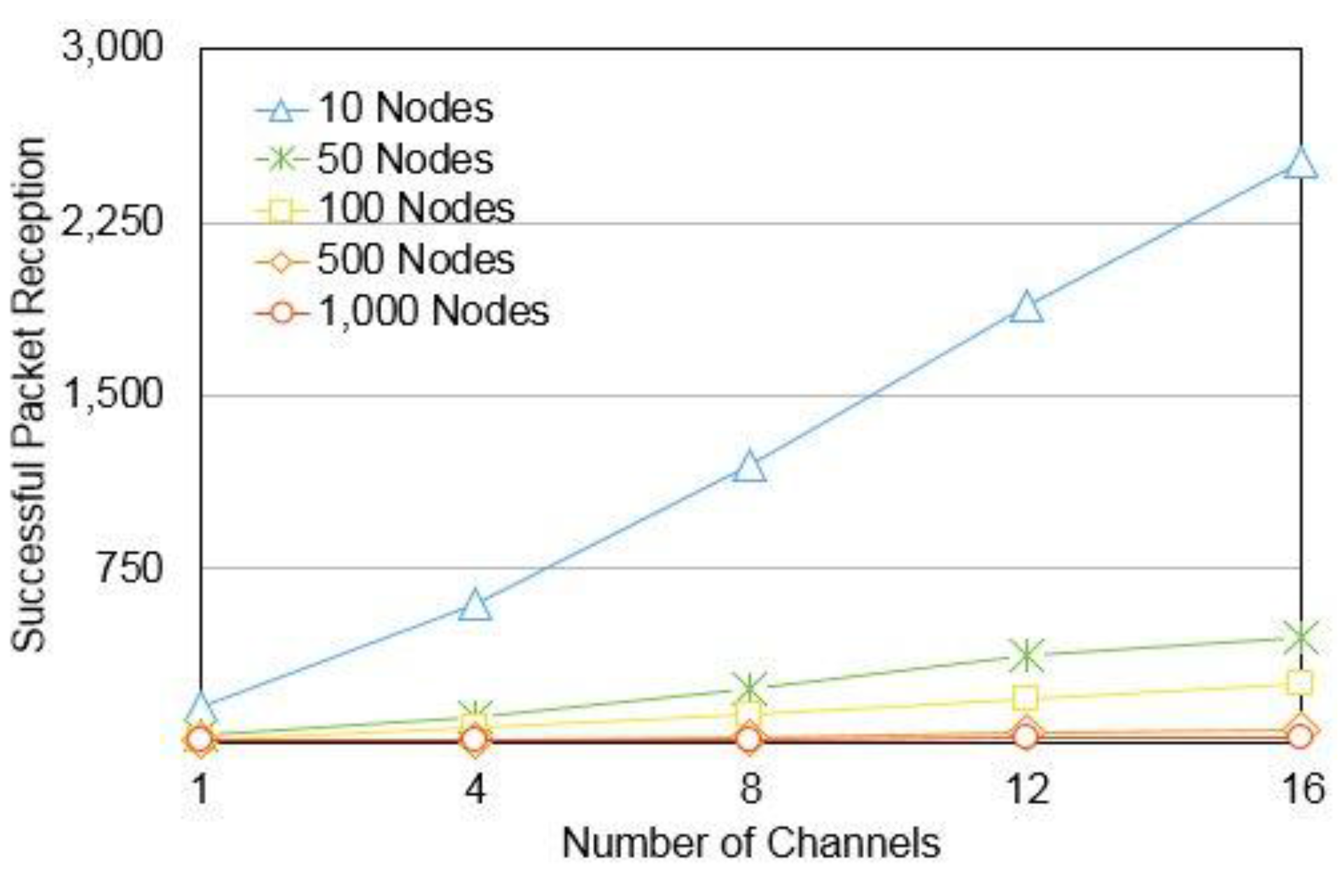
5] compares itself to S-MAC. It utilises traffic patterns to switch the nodes to low power mode whereas S-MAC has a fixed duty cycle for its nodes. These hybrid protocols leverage on combination of CSMA and TDMA to improve their performance, but, under high load conditions, their performance degrades to CSMA or TDMA. These protocols operate on a single channel. The overall load can be reduced by distributing it over multiple channels and partitioning the network into small clusters. Each cluster-head acts as a sink node as part of validation of multi-channel ideology by assigning multiple channels to a CSMA network. With the increase in number of channels, the overall number of successful packet reception increases as shown in
Figure 1. CSMA inherently has higher packet drops due to channel contention. Having multiple channels reduces the packets’ losses, but the solution is bounded by the network node density and number of channels. Keeping this observation in mind, this work focuses on designing a hybrid cluster based multi-channel protocol.
The remainder of the paper is organised as follows:
Section 2 discusses related works.
Section 3 introduces the CMSP protocol.
Section 4 discusses the details of protocol design.
Section 5 presents the performance analysis of the protocol and
Section 6 concludes the paper.
Figure 1.
Shows a comparison of single and multi-channel successful packet transmissions.
Figure 1.
Shows a comparison of single and multi-channel successful packet transmissions.
2. Related Works
Power Aware Multi-Access Protocol with Signalling PAMAS [
6] by S Singh, C.S. Raghavendra is an early WSN implementation that adopted use of different channels for data and signaling. Sohrabi and Pottie [
7] proposed a scheduling scheme with a combination of frequency and time division multiple access. Multi-frequency Media Access Control for WSN (MMSN) by Gang, Zhou
et al. [
8] is one of the earlier full multi-channel medium access control protocols for WSN. The protocol avoids overhead communication of Request To Send (RTS) and Clear To Send (CTS) by assigning one of four different frequencies. All nodes within two hops are evenly assigned the available frequency. The term even assignment is clarified by the authors as being a random assignment of least used frequency within the two hop neighborhood. The medium access is done with a combination of a base frequency used for broadcast and unicast frequency that is assigned to every node such that it can communicate with another node on the same frequency. The inherent issue with this protocol is the randomness in the assignment of the channels. Even-though there are four channels for parallel communication, there is no clear scheduling within the channel due to which, the protocol uses carrier sensing to assign a transmission slot. Tree-based Multi-Channel (TMCP) [
9] tries to address this issue by dividing the whole network into multiple sub-trees and allocating different channel to each sub-tree. With the TMCP channel assignment to the sub-trees, the authors check for the interference radius such that same channel interference is avoided. In networks with high node density, it is difficult to assign different channels to avoid interference. TMCP is an improvement over MMSN, but under dense network conditions, it cannot avoid interference between different sub-trees.
Multi-Channel MAC (MC-LMAC) [
10] uses scheduling to address the issue of interference. It has three modes— common frequency (CF), control message (CM) and Data —that form part of its timeslot structure. In the CF slot, the transmitting and the receiving nodes establish the channel that they would use to communicate. The CM period is to exchange control messages, specifically a beacon is transmitted that provides addressing, synchronization and neighbour discovery. The protocol dynamically assigns channels for the node. Though the protocol addresses interference through scheduling, there is increased latency with increasing node density.
MC-LMAC has greater latency compared to MMSN that uses a multi-channel contention based medium access. A combination of scheduling and contention based medium access would reduce latency, improve throughput, and delivery ratio.
These different protocols show that packet drops are minimized through a scheduling algorithm and network delays are minimized through parallel transmission on different channels.
3. A Clustered Multi-Channel Scheduling Protocol (CMSP)
The multi-channel protocols discussed in the previous section treat the complete network as a whole. Therefore, even with multiple channels the possibility of interference due to overlap of channels is not ruled out. Si
et al. [
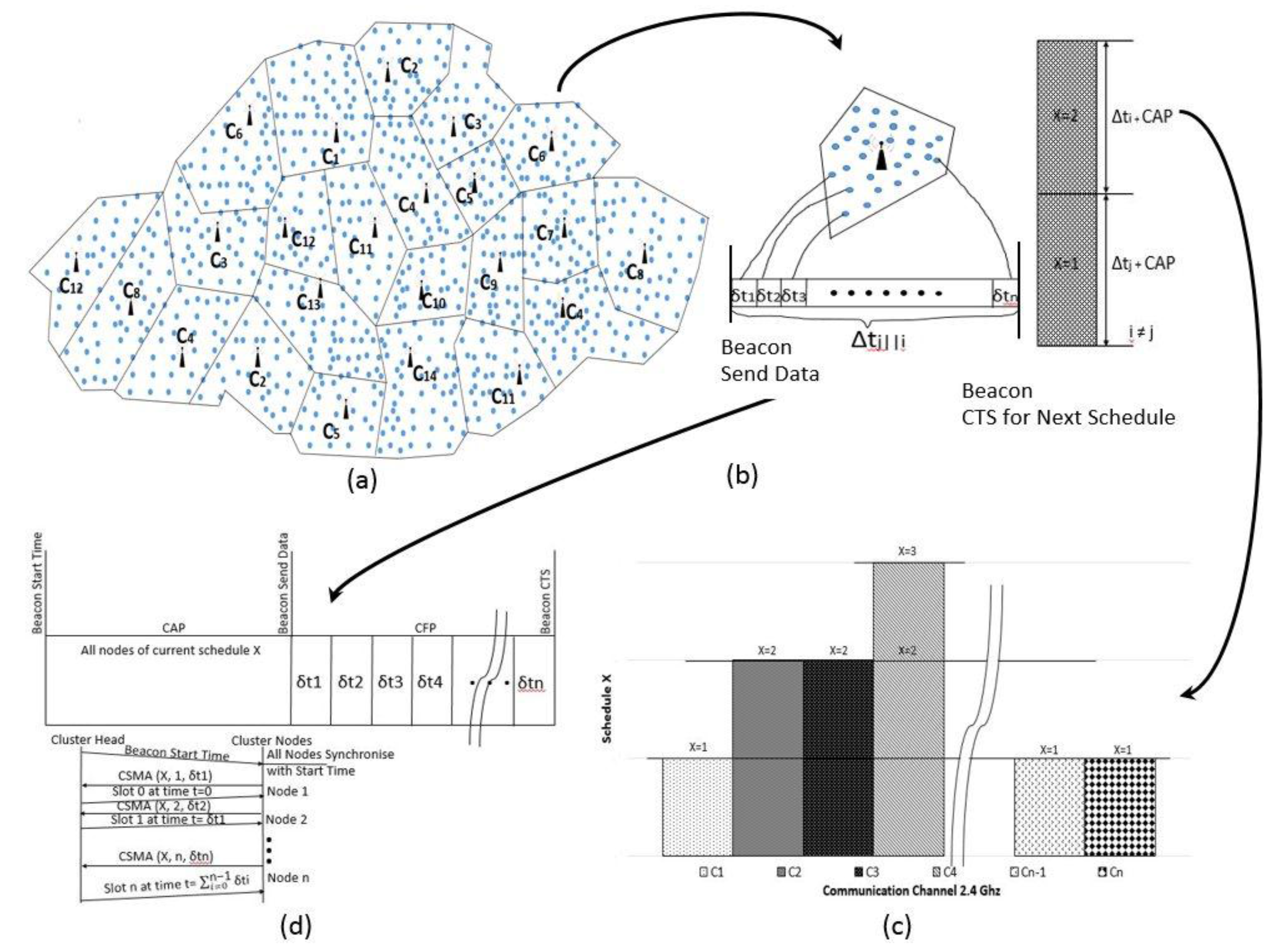
11] note that there is a trade-off of connectivity and interference in the single and multi-channel approach. Spatial partitioning of network as clusters allows for better management of the nodes. This would also address the connectivity and interference trade-off as within the cluster, the nodes would be connected to the cluster-head and the interference is also reduced as the network is partitioned into smaller manageable clusters. In this protocol, it is assumed that there is a possibility of channel overlap and interference, an assumption that is ignored in the literature. Keeping this in mind, the protocol uses two tiers of hybrid scheduling that uses a combination of carrier sensing and time division multiple access. There is scheduling amongst clusters on the same channel termed as Inter-Cluster (
Figure 2c) scheduling and for medium access within a cluster termed as Intra-Cluster scheduling (
Figure 2b).
Figure 2.
Functional Overview of the CMSP protocol: (a) Multi-Channel Voronoi Partition of a Dense Sensor Network; (b) Intra-Cluster Time Scheduling; (c) Inter-Cluster Same Channel Time Scheduling; (d) Intra-Cluster CAP signaling for assigning time slots to nodes.
Figure 2.
Functional Overview of the CMSP protocol: (a) Multi-Channel Voronoi Partition of a Dense Sensor Network; (b) Intra-Cluster Time Scheduling; (c) Inter-Cluster Same Channel Time Scheduling; (d) Intra-Cluster CAP signaling for assigning time slots to nodes.
The intra-cluster scheduling accommodates all nodes on the same channel. Due to limitations of the number of available channels (16 channels at 2.4 GHz band and 10 channels at 902 MHz band), CMSP creates multiple clusters on the same channel and allocates time slots to them. These clusters form part of inter-cluster scheduling that helps minimise interference. The different cluster heads operating on the same channel assign themselves a schedule ID and use Clear To Send (CTS) control signals to coordinate same channel cluster sleep-wake timing. The hierarchical two levels of scheduling allows medium access with reduced packet loss and this can be inferred from Theorem 1 discussed below. With the intra-cluster medium access, all nodes within the cluster are scheduled by the cluster head for data collection.
Theorem 1. Given n cluster-heads on the same channel, the probability of interference pi is greater with contention based channel access than scheduled based channel access.
Proof. The joint probability for a set of cluster heads contending on a given channel Ci is given as in Equation (1).
Ci, Ci+1, …, Cn are n cluster-heads.
The probability of interference, when cluster heads are scheduled and Ci+1 gather cluster data on receiving a CTS from Ci is given by Equation (2).
With intra-cluster interference, we assume
m nodes are allocated in a cluster, then, during the contention access period for time slot assignment, the probability of interference amongst the node accessing the channel would be
On assignment of the slot similar to Equation (2), the probability
Therefore, it can be claimed that with both inter- and intra-cluster medium access, interference is reduced through assignment of time slots. Reduced interference reduces retransmissions that reduces the energy utilization of the node.
Time slot assignment for the inter and intra-cluster scheduling requires contention access amongst cluster-heads and nodes, respectively. To reduce the impact of channel interference, inter-cluster scheduling is performed as part of network initialisation such that network nodes have a static channel assignment. Later, if any node is added to the network, it joins one of the cluster heads by listening on different channels and selecting the channel with the largest signal strength.
Multi-channel protocols have limitations with data broadcast [
10]. CMSP supports unicast, multicast and broadcast that is indirect through the cluster-head. Data is passed to the cluster-head and the cluster-head broadcasts it on base channel
C0 to the other cluster heads. The cluster head to which the unicast or multicast destination node belongs, forwards the data to the particular node or nodes.
Figure 2 gives an overview of the partitioning of the network including the intra and inter-cluster time slot assignment. The inter-cluster scheduling requires the cluster-heads to be awake until the assignment of schedule is complete. The protocol ensures the nodes in the cluster sleep to conserve their power. However, the sleep period is variable and is made dependent on the time it takes to collect data from the on-going scheduled cluster.
The intra-cluster scheduling is designed as a modification to the IEEE 802.15.4 beacon mode. The beacon mode of IEEE 802.15.4 is a hybrid protocol with a contention period for the nodes to join and a contention free period that the nodes use for communication. This contention free period provides a Guaranteed Time Slot (GTS) for the nodes that request for it during the contention period. However, only a limited number of GTS is available [
12]. Priority based GTS allocation schemes [
13] have been proposed for the nodes to join the network. However, with applications like health monitoring, structural monitoring and others that have critical data, having limited number of GTS slots even with the implementation of prioritisation may result in losing some vital data. In this work, the GTS allocation is modified to collect data from all participating nodes.
4. Contention and Receiver Signal Strength Based Multi-Channel Medium Access
CMSP uses a received signal strength indicator (RSSI) based Voronoi tessellation to partition the network as shown in
Figure 2a. The objective of the partition is to create small single hop clusters such that inter-cluster interference is minimised. The following problems would be analysed
A greedy channel assignment amongst cluster-heads
Network Partition into Voronoi tessellations
Network Re-partitioning to include Orphaned nodes
Schedule data collection amongst clusters to minimise inter-channel interference
Intra-cluster data collection schemes
Energy model for CMSP
The analysis for this protocol initialization problem assumes that all nodes are awake, area of deployment is known as “A”, set of nodes in the network is {V} and maximum number of nodes in every cluster is nv. It is also assumed that all nodes are in communication range of one another and have the capability to act as cluster heads.
4.1. A Greedy Channel Assignment amongst Cluster-Heads
The problem is addressed by making available a set of [
14] channels. An initial set of cluster heads
{H} deployed is selected depending on the cluster size |
nv|. The number of cluster heads
H is determined as a quotient of |
V| and |
nv|. The channels are assigned to the set of cluster-heads
H incrementally.
If the |H| ≤ |C| the assignment of the channel to the cluster heads can be defined as follows:
Definition 1. The channel assignment Ch to the cluster-head is an iterative process defined as f:Ch+1→Ch + 1|Ch ϵ C.
If the |H| > |C| the assignment of the channel to the cluster heads can be defined as follows:
Definition 2. f:Ch+1→Ch + 1 mod (|C| + 1)|Ch ϵ C.
The base channel 0, C0 is reserved for inter cluster-head communication and C1 is assigned to channel 1.
The cluster heads in CMSP use a greedy approach to select and advertise their channel. They use the base channel to advertise their selected channel to other cluster-heads. This process uses carrier sense multiple access CSMA. As the number of cluster heads is limited in comparison to the number of network nodes, hence the contention would be limited. All other cluster heads first listen to the on-going transmission by the current cluster-heads and then transmit and, in this process, they collect the channel information of the transmitting cluster-head and know what channels have been taken. When the next cluster-heads contend for transmission, they incrementally select the next channel to advertise.
4.2. Network Partition into Voronoi Tessellations
The CMSP protocol divides the wireless sensor network into Voronoi partitions, considering a set of cluster heads
H = {
h1,
h2, …,
hm}. Then, according to the Voronoi partition for a set of nodes
v, the distance
d(
v,
hi) <
d(
v,
hj), ∀
j ≠ i. This property is useful to create multiple small clusters on different channels. As the nodes closest to the cluster head bind to it, the number of nodes forming part of the intra-cluster network would be small, reducing the load on the cluster head. To form the partition, the cluster heads advertise themselves and all the network nodes that receive the advertisement, check the RSSI of the signal. Hereon, the RSSI is denoted by symbol
S. An empirical verification of the variation in the
S with the distance of separation between the transmitter and the receiver was performed through an experiment using Texas Instruments CC2538 wireless transceivers. The CC2538 uses Printed Circuit Board (PCB) antenna. It is required that all node antenna be oriented in the same direction for measuring
S [
15] correctly. On increasing the distance of separation between the transmitter and the receiver, it was observed that
S decreased and
S increased on decreasing the distance of separation between the radios.
To create the partitions, the network is considered as a static undirected graph G = (V, Eh). Here, V is the set of nodes in the network and Eh is the set of one-hop edges between the nodes and the cluster-head and {h of Eh|h ϵ H}. The network nodes v ϵ V that have a S value greater than a predetermined S threshold Γ to join the advertising cluster head h ϵ H. Formally, it can be defined as:
Definition 3. The existence of an edge Eh between a node v ϵ V and its cluster head h can be established if and only if S ≥ Γ and is given as follows f: V → {∀(v) ∃ Eh ↔ (S ≥ Γ)} ⊂ {V}.
For the partition to be Voronoi, the property d(v, hi) < d(v, hj), ∀j ≠ i should be satisfied. This property can also be stated as r(h) = min{d(h, H)} where r(h) is the largest radius of the partition, assuming the partition is a convex partition and d(h, H) is the distance of the cluster head of the current partition to other cluster heads h ϵ H. In a physical WSN deployment, measurement of physical distances is difficult in comparison to the measurement of S. Therefore, the problem can be reformulated as r(h) = max{S(h, H)} ⇒ min{d(h, H)}, as max{S} would only be for nodes that are closest to the cluster head. Theoretically max{S} would tend to be equal to the cluster heads transmit power. This may result in f:V being an empty set {}.Therefore, we define max{S}|max{S} ⊆ S ∀S ≥ Γ, which makes definition 3 a definition for Voronoi partition.
To define the threshold Γ such that it is the signal strength of the nodes on the edge of the partition, the threshold is made dependent on the number of nodes |nv| in the partition.
|
f:V| ≈ |
nv| such that the nodes at the edge of the partition have
S =
Γ. The signal threshold for edge nodes is determined based on Algorithm 1, shown in
Table 1.
Table 1.
Determination of Signal Strength of Edge nodes.
Table 1.
Determination of Signal Strength of Edge nodes.
| Algorithm 1. RSSI at edge of partition equal to Threshold Γ. |
Input: Cluster heads H, RSSI S, all nodes f:V that have an edge with cluster head
Output: Threshold Γ | while (∆tn ≥ (|f:V|*δtn))
do//∆tn → Total time ∀(v) ∃ Eh and δtn is time for each node including backoff period CSMA (Transmit the S received from h back to h);
count_node++;
if (count_node ≤ |nv|˄S ≥ min(S)) Γ = S
end while |
The algorithm depending on the type of application and its real time response would set a maximum time ∆tn, greater than equal to total time taken by all nodes within the cluster. The nodes within the cluster that receive the cluster head advertisement transmit back to the cluster head their received S value. The cluster head counts the number of nodes for which the received signal strength is just greater than the minimum signal strength min(S) and if the total number of nodes is less than equal to |nv| then the signal strength for the Γ is made equal to the lowest received S.
4.3. Network Re-Partitioning to Include Orphaned Nodes
On the edge of adjacent clusters, there may be nodes that cannot join any cluster because of their S < Γ termed here as orphaned nodes. Orphaned nodes can be defined as a set of nodes Ov ϵ {V}| ∀Ov ∄ Eh. As it has been assumed that all nodes are in communication range of one another; therefore, even these nodes would have received the signal strength of the adjacent clusters.
All Ov nodes consider themselves to be a cluster head and use CSMA to advertise themselves. The first node that wins the channel contention becomes the cluster head. There exists a problem of determining a non-interfering channel for the orphaned nodes.
According to the definition, Ov ∄ Eh there is no edge between Ov and the adjacent cluster’s cluster heads, but during advertisement, all Ov contend to bind with the cluster head and do not succeed. This implies that all Ov nodes know their adjacent channels adj(Ch). Therefore, any Ch ϵ C˄Ch ∉ adj(Ch) obtained by overhearing the cluster head advertisement is a potential channel for the cluster head of the orphan nodes.
The node amongst the orphan nodes that contends for the channel as a cluster head would advertise its channel and the orphaned nodes would join this newly partitioned network. The new cluster head is then added as part of the set {H}.
4.4. Schedule Data Collection amongst Clusters to Minimise Channel Interference
Experimental observations were performed on TI CC2538. The transceiver works on 2.4 GHz band and every channel is 5 MHz apart. The nodes were configured as sets of two transmitters and two receivers. Each transmitter and receiver pair was placed with a separation of 30 cm on a table. Following tests were conducted:
- (a)
Both pairs tuned on the same channel as transmitter and receiver. In this scenario, all packets were lost.
- (b)
Both pairs were tuned on adjacent channels, i.e., Channels 11 and 12. No packet loss due to channel interference was observed.
However, even-though transmission on adjacent channel is not resulting in packet drops a scheduling scheme is required for the cluster head to collect data. This is because if the network is large and dense, with a limited number of channels, there may be overlapping channel assignments amongst clusters as shown in
Figure 1c. Here, interference may occur because channels overlap and all nodes are assumed to be in the communication range of one another. The protocol assigns an integer value to the transmission schedule
X that starts from 0. For all unique channels |
C|,
X maintains its value. As the total number of clusters may be greater than |
C|, every time a channel repeats in any cluster a new schedule is provided and
X is incremented by one. The maximum number of schedules on any one channel can be given as
max(
X) →
sum(|
H|
mod|
C|, |
H|/|
C|). For all {
H} to determine
X, every cluster head
h would use CSMA and broadcast its identification on its own channel,
i.e., a cluster head on channel 1 would contend amongst other channel 1 cluster heads and transmit its schedule
X on a first come first served basis. The process is concurrent amongst different cluster heads operating on different channels and is contention based with a maximum of
max(
X) contentions for intra-channel time scheduling. The cluster head period for each schedule
X is set as ∆t, shown in
Figure 2b. While the cluster-head collects data from within its own cluster, it puts all nodes in other clusters to sleep for time ∆t. To avoid channel contention issue due to clock skew, the cluster heads pass a Clear To Start (CTS) to the next scheduled cluster head once the current cluster head has collected the data within its cluster, shown in
Figure 2d. After all the data has been collected from all the same channels, schedules the nodes are put to sleep for an application dependent time “T
s”.
4.5. Intra-Cluster Data Collection Scheme
Energy is an important metric that dictates nodes to be put in sleep mode. As sleeping nodes are normally in low power modes with no radio listening capabilities, a self-wake scheduling scheme has to be adopted such that all nodes wake at the same time. TDMA protocol allows the nodes to conserve energy through sleep and self-wakeup at the scheduled time, but only a fixed number of nodes can be scheduled in a fixed interval of time. CSMA is not very energy efficient as the nodes have to listen to the channel continuously for channel contention. With TDMA, all nodes have to participate even if some of the nodes do not have data to transmit. CSMA offers the flexibility to the nodes to dynamically transmit data and not participate in a transmission schedule if the node has no data to transmit. Depending on the maximum scheduled time ∆t the cluster head would take to collect the data from the cluster a combination of contention and time scheduling is proposed for intra-cluster data collection. IEEE 802.15.4’s beacon enabled mode has a Contention Access Period (CAP) and a Contention Free Period (CFP). The CAP uses CSMA and CFP provides time slots. CAP and CFP form part of the super-frame as shown in
Figure 3. The inactive period is the duration for which the nodes are put in sleep mode. CAP uses CSMA providing the flexibility for the nodes to join and forward their data to the cluster head. CFP is used to Guarantee Time Slot (GTS) for the nodes. Nodes request for GTS that may be for more than one time slot.
Two parameters Beacon Order (BO) and Superframe Order (SO) are used to specify the duty cycle of the frame. SO and BO vary between 0 and 14 and SO ≤ BO. If BO is 15 then the non-beacon mode is activated,
i.e., communication occurs on CSMA-CA. If SO is 15, then the superframe is deactivated after the beacon. Assuming the frequency of operation to be 2.4 GHz and the “
aBaseSuperframeDuration” is set as 960 symbols (symbol is four bits) [
12]. Beacon Interval BI is given as
BI =
aBaseSuperframeDuration *
2BO symbols. The on time in the Beacon Interval is the Superframe Duration (SD). SD in terms of symbols is given as
SD =
aBaseSuperframeDuration *
2SO symbols. The CMSP protocol does not have an inactive period similar to the inactive period of the BI in the intra-cluster data collection as the inter-cluster data collection scheduler incorporates the inactive or sleep period. Therefore to incorporate IEEE 802.15.4 beacon mode for intra-cluster data collection BI = SD|BO = SO. Assuming the transmission rate is set at 250 kbps at 2.4 GHz then BI = SD = 15.36 ms for BO, SO = 0 and BI = SD = 251.65 s for BO, SO = 14. Reducing the transmission rate would increase the time of BI and SD but would also keep the radios active for a longer duration of time, which is unwanted energy expenditure. The IEEE 802.15.4 standard puts a transmission rate dependent upper and lower bound to the active period of the communication. Applications requiring active time period less than 15.36 ms would waste the rest of the active cycle and application requiring time greater than 251.65 s would need to repeat the cycle. Repeating the cycle may not always be possible.
Figure 3.
IEEE 802.15.4 Beacon Mode Frame Format.
Figure 3.
IEEE 802.15.4 Beacon Mode Frame Format.
M.H.S Gilani
et al. [
16] have noted that by varying the time slots channel utilization is improved and latency is reduced. They discuss using CFPs’ GTS slots for TDMA to improve channel utilization. Their proposition is an adaptation of IEEE 802.15.4. Their algorithm monitors the traffic and channel utilization to trade-off between TDMA and GTS maintaining the
aMinCAPLength for the contention period. If traffic is high and there is a lot of contention, nodes are assigned TDMA time slot depending on the amount of data in their queue.
The time ∆t scheduled by the inter-cluster data collection scheduler is variable for every cluster such that complete data is collected in a single schedule. As the variable time depends on the data size and number of nodes, ∆t may tend to be greater than IEEE 802.15.4’s maximum time of 251.65 s. In this implementation, we adopt the frame format of 802.15.4 with modifications proposed in [
16] but instead of having limiting BI with a maximum time it is equated to ∆t and BO is computed,
i.e., BO or SO is not limited to 14 but can be varied based on the requirement of the application.
The implementation in this work as given in Algorithm 2 shown in
Table 2, makes the cluster head broadcast the beacon and the nodes respond to the cluster head in a greedy manner on a first come first serve basis on the CAP of IEEE 802.15.4. Only nodes that belong to the current schedule participate in the CSMA and transmit the amount of time δ
t as shown in
Figure 2d.
Table 2.
Computing beacon order (BO) and superframe order (SO) based on Time ∆t and δt.
Table 2.
Computing beacon order (BO) and superframe order (SO) based on Time ∆t and δt.
| Algorithm 2. Intra-cluster Time for Data Collection. |
| Input: ∆t, δt aBaseSuperframeDuration, X Output: BO, SO | Clusterhead h → Broadcast (beacon, X);
∆t → 0;
∀(v) ∃ Eh respond
CSMA (Transmit n_Id, δt);
t_slot → t_slot + δt; //t_slot TDMA time slot
Clusterhead h →Broadcast (t_slot, n_Id);
Clusterhead h: ∆t → ∆t + δt;
BO = SO = log2 (∆t/aBaseSuperframeDuration); |
This allows cluster head to compute total time ∆
t. All the nodes that do not belong to this schedule are put to sleep for time ∆
t. As SO is made dependent on time ∆
t, all nodes within the cluster can be accommodated. As all nodes get their δ
t time, this scheme provides a GTS to all nodes participating in that communication. Algorithm 3 showing the CMSP protocol is given in
Appendix A,
Table A1.
4.6. Energy Model for CMSP
CMSP’s hierarchical network architecture with inter and intra clustering reduces communication overhead and minimizes energy consumption. The different energy consumption components are inter-cluster channel allocation, orphan node channel allocations, schedule assignments for inter- and intra-clusters.
The channel allocation and schedule assignment contribute to one time setup energy cost Esetup. The communication involving intra-channel data collection and scheduling amongst different cluster head results in on-going energy expenditure.
The CMSP protocol starts with assignment of channels to cluster head. This process uses greedy channel access by cluster head using CSMA where the energy expenditure (EiCCA), depends on the number of backoff and possible retransmission. Once the cluster head selects a channel, it broadcasts its channel number such that all nodes according to Algorithm 1 switch their channel to match the channel of the current cluster head. The energy expenditure for this broadcast is EgTX. All the pockets of nodes that could not join a cluster head become orphaned nodes. These nodes use CSMA and try to advertise themselves as a new cluster head. The energy consumption for this is (EOiCCA). The node that wins becomes a cluster head broadcasts its channel. The energy consumption for this is EOgTX. For data collection within the clusters, GTS time slots need to be assigned that requires CSMA. The energy consumption for this process is EnvTX and then transmission of a time slot for all nodes. EnvTX, Et is the total energy consumed that is the sum of Esetup and ETX, where ETX is energy expended in the node transmissions and V is the total number of nodes.
5. Results and Discussion
The CMSP is evaluated using simulation on Castalia [
17]. The performance of CMSP is compared with Tree-based Multi-Channel (TMCP), Multi-frequency Media Access Control for WSN (MMSN), Multi-Channel MAC (MC-LMAC). CMSP has been evaluated and compared with respect to the node density and number of channels. Power consumed, Throughput and Delivery ratio are the performance metrics that have been measured. Power consumed is a measure of the amount of battery power expended for network setup and functioning. Delivery ratio is the number of data packets successfully delivered to the total number of packets transmitted by the MAC layer. Throughput has been calculated as the total traffic through the MAC layer per unit time. The simulation parameter are as set in
Table 3.
Table 3.
Simulation Parameter.
Table 3.
Simulation Parameter.
| Area of Deployment | 50 m × 50 m |
| Number of Nodes | 5 to 100 nodes |
| Transmit Power | −15 dBm |
| Data Rate | 250 kbps |
| Number of Channels | 16 |
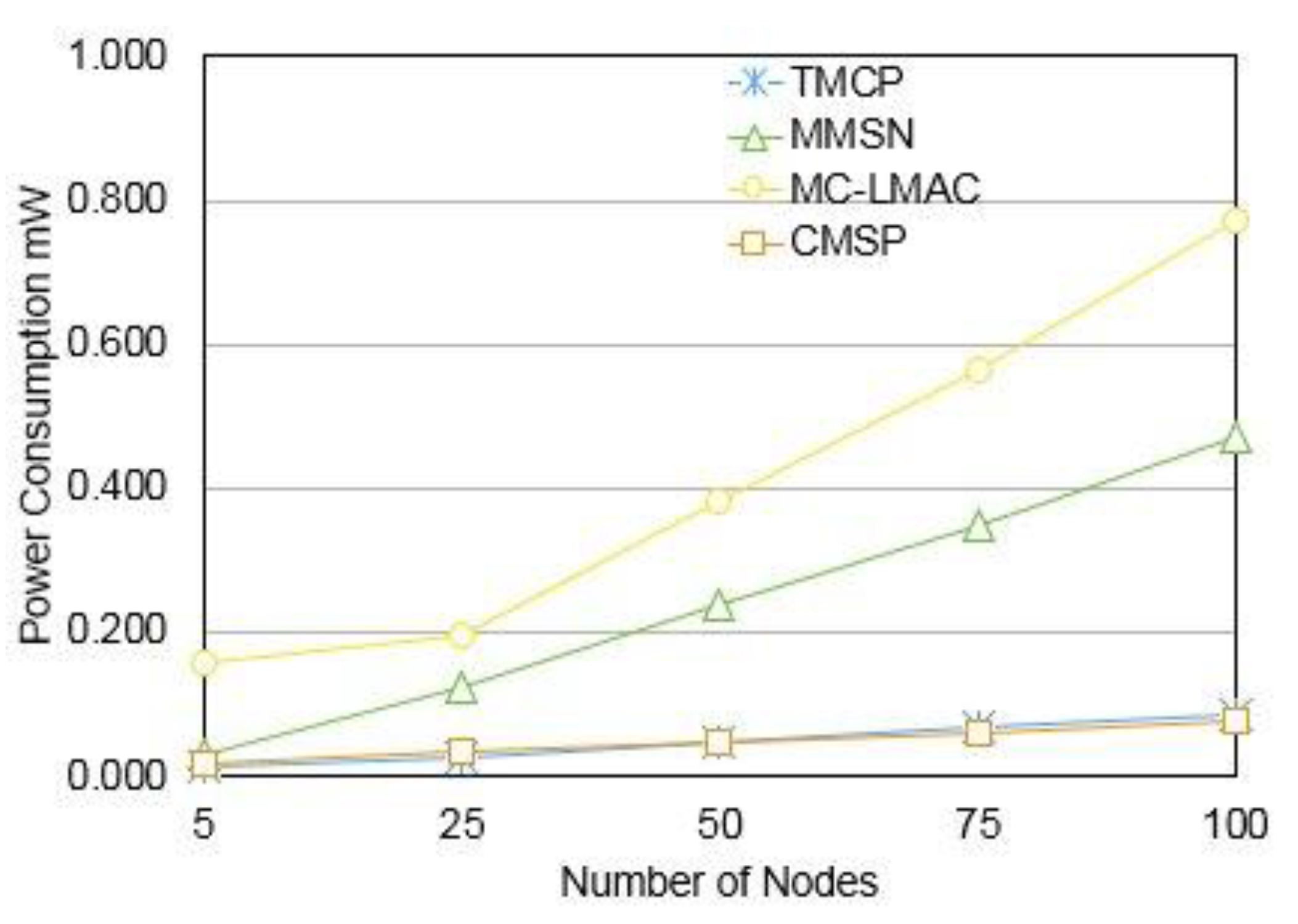
The tests conducted to study the performance with respect to node density, involves keeping the deployment area constant and increasing the number of nodes from five to 100. To study the performance deployment area constant and increasing the number of nodes from five to 100. To study the performance with respect to the number of channels, the work considers an operating frequency of 2.4 GHz that offers a maximum of 16 channels. The power consumption increases as the node density increases in the network as shown in
Figure 4. The protocols considered are hybrids, having scheduled access and contention based access to the media. With increasing node density, the channel contention of these protocols results in retransmissions that increases the power consumption. The other source of power consumption is the setup cost. MMSN, TMCP and CMSP have one time network setup cost. MC-LMAC is designed for
ad hoc networks and requires the nodes to be reconfigurable that increase the overhead. MMSN and MC-LMAC consider communication to be separated by two hop neighbours. In high density networks, ensuring two hops to neighbours is difficult as the radios would cause interference. TMCP uses a tree-based approach to cluster the nodes in the network. Under high density condition with a limited number of channels, there would be interference. CMSP considers the possibility of interference and, to mitigate it, incurs a one-time setup cost to create the inter-cluster scheduling. This one-time setup involves channel assignment, network partition and repartition and inter-cluster schedule assignment. The operational cost of the network involves the intra-cluster scheduling and the use of base channel
C0 for communication amongst cluster-heads. As the network load is distributed over multiple channels according to the greedy channel assignment, the power consumption of the network reduces due to the reduction in channel contention, as shown in
Figure 5.
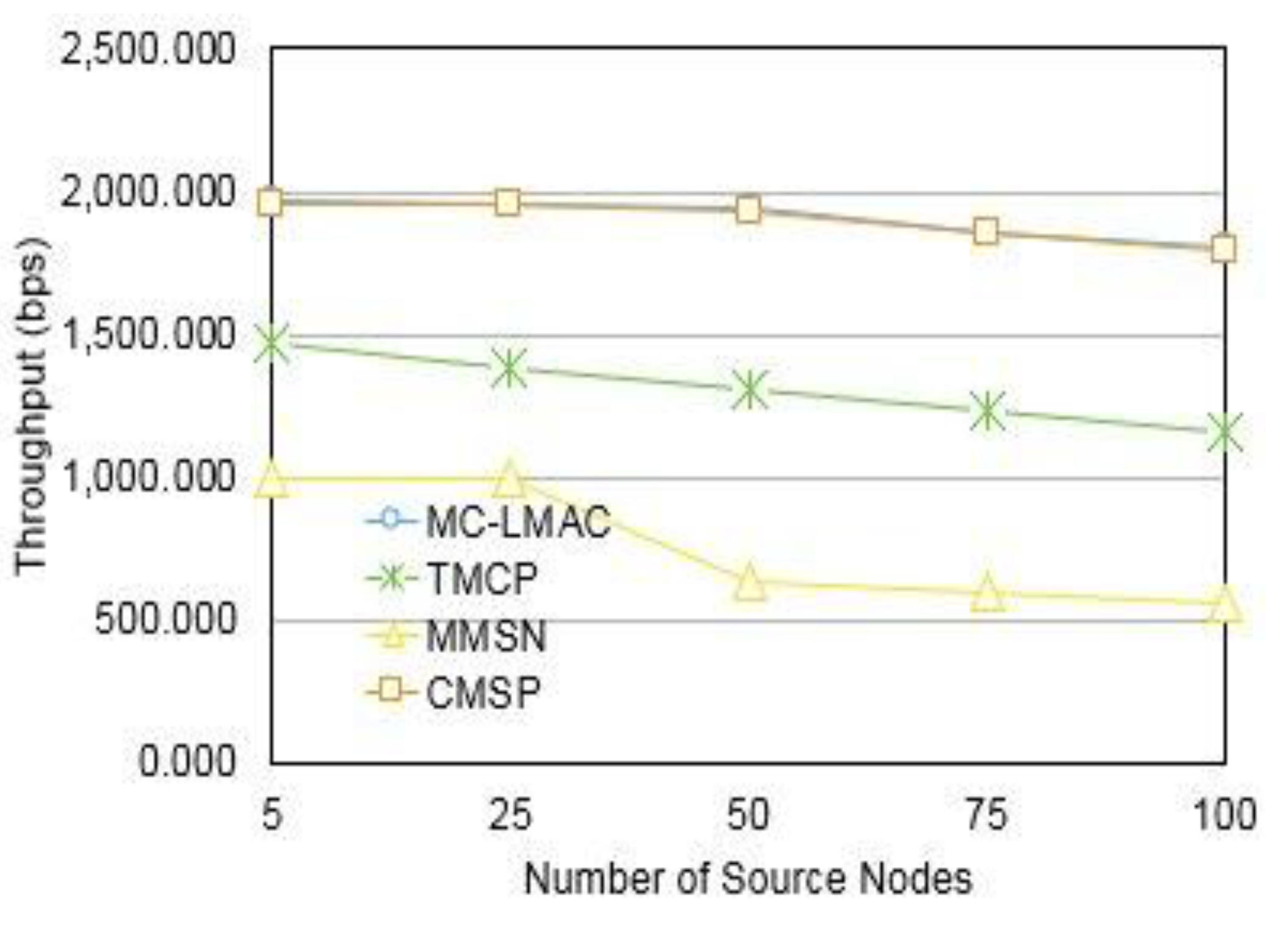
The throughput of different protocols is compared with respect to the number of nodes and multiple channels in
Figure 6 and
Figure 7, respectively. With respect to increasing node density, CMSP has a throughput slightly greater than MC-LMAC. This can be attributed to the static nature of network for which CMSP is designed. TMCP performs poorly due to the inherent issue of media contention. As the number of channels are increased, more nodes get access to the channel. This improves the overall throughput of the network.
Figure 4.
Power consumption vs. number of nodes.
Figure 4.
Power consumption vs. number of nodes.
Figure 5.
Power consumption vs. number of channels.
Figure 5.
Power consumption vs. number of channels.
Figure 6.
Throughput vs. number of source nodes.
Figure 6.
Throughput vs. number of source nodes.
Figure 7.
Throughput vs. number of channels.
Figure 7.
Throughput vs. number of channels.
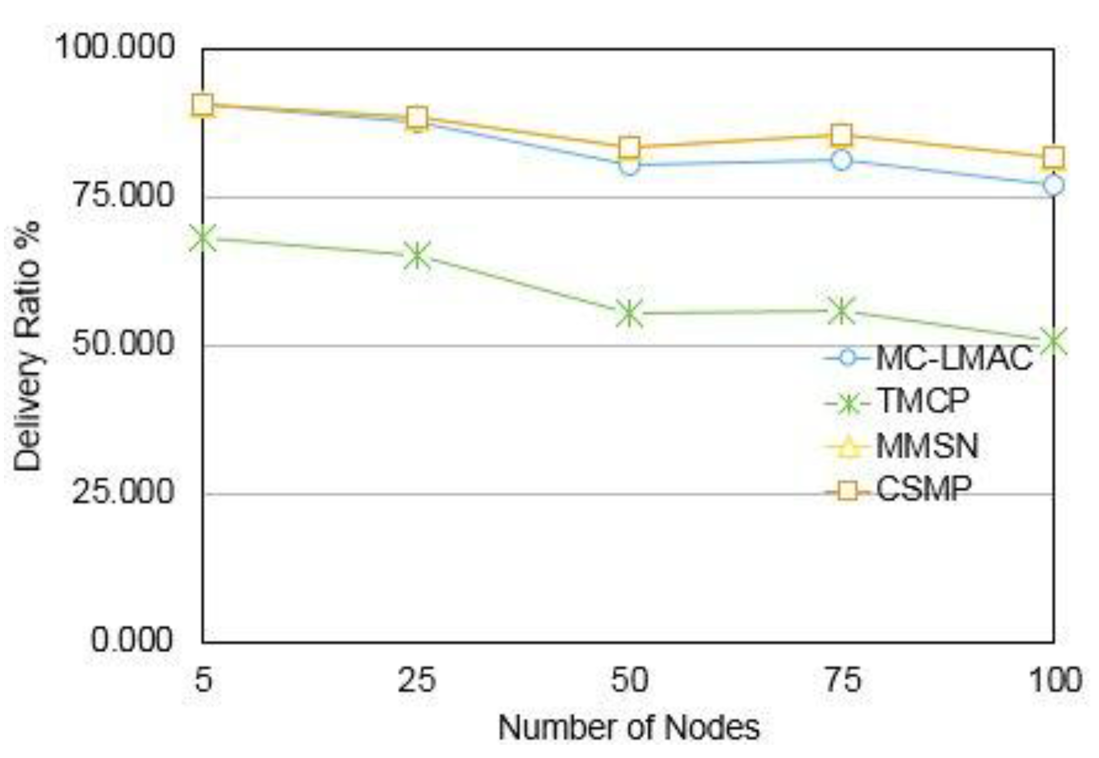
The number of packets successfully received by the receiver node with respect to the number of packets transmitted, reduces, with increasing node density, as shown in
Figure 8 and
Figure 9. With increasing channels, the delivery ratio increases to ~90%. The literature claim ~98%–99% delivery ratio for the protocols.
Figure 8.
Delivery ratio % vs. number of nodes.
Figure 8.
Delivery ratio % vs. number of nodes.
Figure 9.
Delivery ratio % vs. number of channels.
Figure 9.
Delivery ratio % vs. number of channels.
Even though the protocols use scheduling, their delivery ratio is low. This is because of channel contention due to snooping and searching for channels. Therefore, though the majority of the time the communication is scheduled, there are losses when contention mechanisms are used to determine the channels. The delivery ratio is equivalent to MMSN. This is attributed to the fact that MMSN has a low setup cost similar to CMSP. TMCP has a low setup cost, but the operational cost due to high node densities and insufficient channels is high. A summary of the setup and operation cost of the different protocols is given in
Table 4.
Table 4.
Comparison of setup and operational cost for different protocols.
Table 4.
Comparison of setup and operational cost for different protocols.
| | Initial Setup Cost | Operational Cost |
|---|
| CMSP | Contention based media access to assign channels and create clusters through partitions | Media access using Guaranteed Time Slots (GTS) and GTS assignment using contention based media access. |
| MC-LMAC | Supports Ad-hoc network so no initial setup cost | The protocol uses a control frequency in every time-slot to inform other node of their frequency. The receiver changes its frequency to the frequency of the transmitter to establish communication. The cost incurred is due to listening on control frequency for every iteration in the communication |
| MMSN | Uses Contention based media access to assign and broadcast their assigned frequency amongst 2-hop neighbours. If more channels are available then this protocol uses a pseudo random technique for 2 hop neighbours that requires exchange of these numbers through channel contention. | This protocol uses frequency snooping and a backoff mechanism to listen and select a transmitter receiver pair. Once a transmitter receiver pair is selected a transmission schedule is used for communication. |
| TMCP | Network with k sub-channels partitioned with k sub-trees and each sub-tree assigned a unique channel | Contention based channel access within sub-trees. |
6. Conclusions
In this work, we have presented CMSP protocol for dense IoT based wireless sensor clouds. The protocol is designed for static networks. It uses multiple channels and a hierarchical scheduling scheme to reduce the power consumption and improve the delivery ratio and network throughput.
Simulation results show that CMSP performs better than MC-LMAC, MMSN for power consumption. With respect to delivery ratio CMSP performs better than TMCP and MC-LMAC and CMSP has better throughput in comparison to MMSN and TMCP.
The modification of the IEEE 802.15.4 for the intra-cluster scheduling allowed for larger number of nodes to have GTS timeslots in the CFP. The advantage of CMSP over other protocols is its implementation that involves minor modification to the CFP of IEEE 802.15.4 and adding an extra scheduling mechanism.
As part of future work, we intend to implement this on physical motes and compare the performance of the physical network with these simulation results.


