Dynamic Cooperative MAC Protocol for Navigation Carrier Ad Hoc Networks: A DiffServ-Based Approach

1
Department of Control Engineering, Naval Aeronautical and Astronautical University, Yantai 264001, China
2
The 92664th unit of PLA, Qingdao 266000, China
*
Author to whom correspondence should be addressed.
J. Sens. Actuator Netw. 2017, 6(3), 14; https://doi.org/10.3390/jsan6030014
Submission received: 21 October 2016
/
Revised: 16 July 2017
/
Accepted: 26 July 2017
/
Published: 8 August 2017
(This article belongs to the Special Issue QoS in Wireless Sensor/Actuator Networks and Systems)
Abstract
:In this paper, a dynamic cooperative MAC protocol (DDC-MAC) based on cluster network topology is proposed, which has the capability of differentiated service mechanisms and long-range communication. In DDC-MAC, heterogeneous communications are classified according to service types and quality of service (QoS) requirements, i.e., periodic communication mode (PC mode) is extracted with a QoS guarantee for high-frequency periodic information exchange based on adapt-TDMA mechanisms, while other services are classified as being in on-demand communication mode (OC mode), which includes channel contention and access mechanisms based on a multiple priority algorithm. OC mode is embedded into the adapt-TDMA process adaptively, and the two communication modes can work in parallel. Furthermore, adaptive array hybrid antenna systems and cooperative communication with optimal relay are presented, to exploit the opportunity for long-range transmission, while an adaptive channel back-off sequence is deduced, to mitigate packet collision and network congestion. Moreover, we developed an analytical framework to quantify the performance of the DDC-MAC protocol and conducted extensive simulation. Simulation results show that the proposed DDC-MAC protocol enhances network performance in diverse scenarios, and significantly improves network throughput and reduces average delay compared with other MAC protocols.
1. Introduction
Emerging advantages of network technique inspire other fields to solve their own bottlenecks through networked approaches [1]. In our research, we are devoted to putting forward a network-aware solution for a bottleneck of modern navigation technology, which prevents it from reaching a higher level [1,2,3]. More specifically, the navigation precision of each navigation technology is closely related to the self-contained degree of the navigation system; on one hand, we can upgrade its integrity to enhance the navigation precision, e.g., by augmenting other navigation equipment or replacing it with a high precision navigation system, which will lead to additional economic investment and physical load; on the other hand, we can simplify the complexity of the navigation equipment to alleviate the burdens above, e.g., by the reduction of navigation equipment or its replacement with a low-cost navigation system, although its navigation capacity will be degraded accordingly. In references [2,3,4], we proposed a navigation-oriented network—navigation carrier ad hoc networks (NC-NET)—to solve the localization, target tracking, and multimedia data exchange problems through a network approach. The proposed NC-NET, which is essentially an ad hoc network between navigation carriers (NCs), is surveyed as a new network family. Moreover, some of the protocols and mechanisms have already been investigated, including (i) the protocol framework, and the models in the physical layer [2,3]; (ii) a distributed multi-weight data-gathering and aggregation protocol for cluster topology, i.e., DMDG protocol [2]; (iii) a grid-based cooperative QoS routing protocol with fading memory optimization, i.e., FMCQR protocol [3]; and (iv) a network-based localization mechanism [4]. As part of a series of research work, the main objective of this paper is to develop a MAC protocol with full account of the features of NC-NET.
Figure 1 illustrates a typical use of NC-NET, which is a scenario of multi-service transmission among a set of unmanned aerial vehicles (UAVs); herein, each UAV is equipped with an NC-NET terminal with a unique ID, and thus the objective node will exchange the wireless packets with its neighbors at each round, according to the uniform NC-NET protocols. Thus, in this kind of application, an efficient MAC protocol is indispensable for NC-NET, which has the following design challenges: (i) multiple traffic services; (ii) three-dimensional large-scale active region (e.g., aerial, ground or water surface), and long-range distance between nodes (e.g., line-of-sight, beyond-line-of-sight); and (iii) heterogeneous types of NC-NET nodes. For simplicity, but without loss of generality, an essential NC-NET is discussed at length in the research, in which the open issues surrounding general-purpose MAC protocols are analyzed in detail. However, there are also several common points between NC-NET and the previous ad hoc network, e.g., decentralization, infrastructure-less, and self-configuration [2,3,5]. Moreover, several illustrations of NC-NET adopt the general-purpose technologies of ad hoc networks, such as TDMA and CSMA/CA. From this point of view, NC-NET can also be investigated as a special form of ad hoc network. In previous literature, several effective technologies for MAC protocols have been studied in depth, which can be used as a reference for our research, e.g., directional antennas, multi-channel diversity, differentiated-service mechanisms, and cooperative communication.
There are several common points between NC-NET and previous ad hoc networks, such as decentralization, lack of infrastructure, and self-configuration [6,7]. Moreover, several illustrations of NC-NET, e.g., tactical targeting network technology (TTNT) [8], have adopted the general-purpose technologies of ad hoc network such as TDMA and CSMA/CA. From this point of view, NC-NET can also be investigated as a special form of ad hoc network. In previous literature, several effective technologies for MAC protocols of ad hoc network have been studied in depth, and can be used as a reference for our research, i.e., directional antennas [9,10,11], multi-channel diversity [12], differentiated-service mechanisms [13,14,15,16,17,18], and cooperative communication [19,20,21,22,23,24].
Following detailed analysis, it is clear that the results for challenge (i), challenge (ii), and their hybrid are extensive; however, in terms of challenge (iii), the integrated investigations on challenges (i) and (ii) are quite limited. From the above analysis, we identify the missing properties in the existing work for QoS provisioning in NC-NET and introduce the design and implementation of a new MAC protocol for NC-NET. In this paper, we propose a hybrid approach, namely, a DiffServ-based dynamic cooperative MAC (DDC-MAC) protocol, in combination with the aforementioned techniques for NC-NET. The key contributions of this work and highlights of DDC-MAC are listed as follows: First, a system model is presented that exploits the merits of the aforementioned issues, including an adaptive array hybrid antenna system, multi-channel environment and cluster-based network topology. Second, the proposed DDC-MAC protocol is designed in detail with the following features: (i) a DiffServ mechanism is proposed to realize the parallel transmission of multiple services with QoS guarantee; (ii) a multi-priority policy is presented to reduce the probability of contention and collision, and to reassign the access sequence; (iii) an adaptive channel back-off sequence (ACBS) is proposed as a reference for lower-priority pairs to switch directly among data channels without additional negotiation packets; and (iv) an optimal-relay-based MAC procedure is deduced to handle link failures in long-range transmission. The performance of DDC-MAC is theoretically analyzed and evaluated. Finally, the results demonstrate the efficiency of DDC-MAC by comparing it with other contemporary protocols.
The remainder of the paper is organized as follows. Section 3 presents the system description and traffic models. Section 4 provides a detailed description of the proposed DDC-MAC protocol. In Section 5, we analyze DDC-MAC in terms of the searching probability of next-hop nodes and saturated throughput. In Section 6, we evaluate DDC-MAC based on extensive simulations. Finally, conclusions are given in Section 7.
2. Related Works
Although extensive recent papers delve specifically into QoS-aware MAC problems, the literature pertaining to QoS MAC for high-dynamic ad hoc networks is extremely limited, and that addressing NC-NET remains almost non-existent, in spite of being described as an open issue at the link layer in reference [1]. In this section, we analyze the related works on typical QoS-aware MAC protocols for wireless networks.
Directional antennas can offer clear advantages in terms of improving the signaling range without extra power (as opposed to omni-directional antennas), especially for long-range transmission. Previous research has incorporated directional antennas in the design of MAC protocols. DMAC [5] is one of the earliest of these. This protocol is based on a modified 802.11 MAC protocol [6], and uses a per-sector blocking mechanism to block a sector once it senses a request-to-send (RTS) or clear-to-send (CTS) packet, whereas the data packets are transmitted through directional beams. This kind of mechanism is beneficial for spatial reuse, end-to-end transmission delay, and power consumption in data transmission [7]. Unfortunately, some problems also arise from the use of directional antennas, such as the deafness problem [8], the new hidden terminal problem [8,9], and the head-of-line (HOL) blocking problem [10]. Previous directional MAC protocols have already defined several techniques to handle these problems [8,9,10,11,12]. However, they mainly focus on some specific aspects; for example, augmentation of the busy-tone channel [10,11], attachment of a start-of-frame [8,9], or multi-channel diversity [12,13]. Nevertheless, the question of how to combine these techniques in a large-scale mobile wireless network and maximize the advantages of directional antennas in a multi-service environment is still an open issue, motivating the research in this study. Furthermore, in view of the complex communication challenges in NC-NET, in this research, the usage of directional antennas is combined with other techniques, i.e., differentiated services and cooperative communication.
Differentiated services (DiffServ) is a widely known and utilized technique for QoS provision in networks with multiple traffic services [14], which are differentiated and prioritized based on one or more criteria and formed into several traffic classes. In the literature [14,15,16,17,18], the majority of DiffServ mechanisms are proposed for wireless multimedia sensor networks (WMSN), and can be classified according to various types of criteria, such as drive-mode-aware criteria, QoS-aware criteria, and other criteria. In references [15,16], the services are differentiated based on drive modes, whereby the cyclically occurring services are classified as a time-driven class, whereas stochastic services are classified as an event-driven class. Thereby, the medium access of the two classes is realized based on schedule-based MAC and contention-based MAC, respectively, or hybrid solutions including TDMA/CSMA, CDMA/CSMA, FDMA/CSMA, etc. In references [17,18], multiple services are classified based on QoS-aware criteria such as delay sensitivity and packet loss sensitivity. Saxena et al. [17] proposed a CSMA/CA approach, classifying the co-existing packets into two categories, i.e., streaming multimedia (over UDP) packets and Best Effort FTP (over TCP) packets. Moreover, Diff-MAC [18] is designed with the key features of service differentiation and QoS guarantee for heterogeneous traffic (e.g., video, voice and periodic scalar data), which is differentiated into three classes, i.e., real-time (RT) multimedia traffic, non-real-time (NRT) traffic and best effort (BE) traffic. Note that these DiffServ mechanisms are mainly proposed with one of or a hybrid of the following features: (i) adaptive contention window (CW) adjustment, (ii) dynamic duty cycling (changing active time), (iii) fragmentation and message passing for long packets, and (iv) intra-node and intra-queue prioritization [18]. However, these MAC protocols cannot fulfill the unique requirements of core-function-aware networks. Take NC-NET, for example; navigation service is the core function of NC-NET, which is essential to other multimedia services, even the services with stringent constraints on real-time variable bit rate, packet loss, and average delay. Thus, in this study, the design and analysis of the DiffServ mechanism, which can separate the kernel service from other functions, will be a basis for other technical details.
Cooperative communication is another effective technique for realizing the advantages of spatial diversity, especially when NC-NET requires robust and real-time data communication, or the communication is impacted by high mobility, intermittent connectivity, and unreliability of the wireless medium. Thus, the theory behind it, depending on the application scenarios, can be classified into two categories: cooperative diversity, and packet relay by selected neighbor nodes. Cooperative diversity aims to offset the multi-path fading effect of wireless channels through multiple cooperative antennas, which can maximize the total network channel capacity [19,20,21]. For instance, CoopMAC [20] takes full advantage of the broadcast nature of the wireless channel, thus creating spatial diversity. Packet relay by selected neighbor nodes improves the link utilization probability by transmitting through the selected relay nodes, instead of transmitting directly to the destinations. In previous works, EC-MAC in reference [22], and 2rcMAC in reference [23] are similar to our proposed protocol. EC-MAC adopts the best partnership selection algorithm to select the cooperative node with the properties of best channel conditions, highest transmission rate, and most balanced energy consumption. In 2rcMAC, the nodes update their relay table through a passive listening method, and obtain spatial diversity by a two-best-relay approach. However, this literature [20,21,22,23] is mainly confined to the scenarios with features such as short transmission range, low dynamic or static nodes, and omni-directional antennas. The cooperative MAC for large-scale sparse network is still an open issue, and does not have full-rate network codes for directional transmission [24,25,26]. Both of them restrain the use of cooperative communication in a practical large-scale dynamic network. Furthermore, in the majority of works, only the relays that can decode the packet successfully during the first transmission can be activated and get involved in the possible ARQ retransmission; meanwhile, the other relays keep silent during the whole ARQ process. Nevertheless, they ignore the fact that the relays, which cannot decode the packet correctly during the first transmission, still have the chance to decode the packet correctly in the ARQ process.
3. System Description and Related Models
The navigation-oriented NC-NET is described by an undirected graph , where denotes the set of sensor nodes and means the node with a unique ID , denotes the set of edge and edge indicates that node can receive the information from node , and indicates the set of work radius and means the work radius under the given data rate Mbps.
3.1. Propagation and Channel Models
For simplicity, but without loss of generality, we ignore the unknown and heterogeneous factors of the signal propagation environment, and adopt a free space propagation model [27]:
where denotes the received power of the packet from node to , denotes the transmission power, denotes the distance between transmitter and receiver, is a path loss exponent related to the propagation environment. , with and are antenna gains of transmitter and receiver. Thus, we have the absorption loss (in dB) , where denotes the free space loss in dB, is the electromagnetic frequency in GHz, and is the distance between transmitter and receiver in km [28]. Let and , combine with the practical test results of the TTNT data link for the data rate [8], and then the propagation parameters can be summarized as Table 1.
3.2. Antenna Model and Communication Modes
Assumption 1. (Adaptive antenna): Each node is equipped with an adaptive array antenna system, which has two transmission modes in terms of omni-directional and directional modes, as shown in Figure 2. Moreover, the receiving mode of the antenna system is omni-directional.
Assumption 2. (Directional beam): Let the ideal model of the beam coverage region be a spherical sector , where denotes the maximal permission range of sender (), is the beam-width of its main-lobe. Suppose that the main-lobe gain is isotropic, and the gains of side-lobes and back-lobes are ignored. Moreover, the direction of the main-lobe can be rotated adaptively around the three-dimensional detecting region.
The relationship between omni-directional transmission range and directional range can be expressed as follows:
Lemma 1.
Let the transmission be directional and the reception be omni-directional, the transmission range under the given transmission power can be determined from
where is the path loss exponent, i.e., .
Let be and under a given transmission power, the range of directional transmission (DT) is equivalent to times of omni-directional transmission (OT). If an omni-directional broadcast request is received, or the azimuth of the destination node is unknown, the transmitter will send a packet in omni-directional mode (denoted by OT). If the azimuth of the destination node is known, or a directional transmission request is received, the transmission node will send a packet in directional mode (denoted by DT). Moreover, to extend the transmission radius, the relay node for retransmission mainly works in DT mode (denoted by DR). Thus, the communication modes can be specified as follows: (a) omni-directional transmission and omni-directional reception (OT-OR), (b) directional transmission and omni-directional reception (DT-OR), and (c) directional transmission, directional relay and omni-directional reception (DT-DR-OR). Let , , and be the ranges of the three modes, respectively, , and ; the maximal transmission range can be calculated by (2) as , , .
4. DiffServ-Based Dynamic Cooperative MAC Protocol
In this section, we introduce a DiffServ-based MAC protocol (DDC-MAC) and its key features for QoS-provisioning and adaptation according to different types of service. The proposed protocol consists of two compatible sub-protocols: (i) time-driven-based periodic communication, denoted as a PC sub-protocol, and (ii) event-driven-based on-demand communication, denoted as an OC sub-protocol.
4.1. MAC Sub-Protocol for Periodic Communication
In NC-NET, PC service is the core transmission demand with the characters in terms of delay sensitivity, packet loss sensitivity, and high communication frequency. In this section, we propose a collision-free MAC sub-protocol, which adopts DiffServ-based clustering topology and adapt-TDMA, to handle these periodic communication requests.
4.1.1. Adaptive TDMA Schedule
The basic hypothesis applicable to DiffServ-based clustering topology is outlined as follows:
Assumption 3. Under PC mode, only one member of a 1-hop cluster is allowed to send the packet at the same time, while the other nodes overhear the medium.
Assumption 4. The time axis of the adapt-TDMA schemes is divided by means of round, frame, and mini-slot, with the relationships , .
Assumption 5. The major function of a cluster-head is assumed to have the following features: (i) its function is to monitor, supervise, and gather the state change from its cluster members; (ii) it broadcasts a common management packet (denoted by CM) periodically, including a synchronized clock, access schedule (AS), etc.; and (iii) it is not designated as fixed relay nodes, in order to avoid the problems of “hot spots” and imbalance link loads.
As depicted in Figure 2, round indicates the total time for all members of a cluster to update the data according to AS. Frame is the duration for one member to update its data, and can be subdivided into two sub-frames: a control sub-frame (C-frame) and a data sub-frame (D-frame). C-frame is the time for schedule, reservation, and contention window; D-frame is the time duration to handle the packet. Mini-slot is the fixed time duration to process the data less than bits. , ; herein, and are two known constants, which represent the lengths of the and , respectively.
Furthermore, a parity field (PF) is introduced in the head of the C-frame, which is a 2-bit code with settings as follows: PF = 00 (i.e., overhear or idle mode in PC), PF = 01 (i.e., active mode in PC), PF = 10 (i.e., initial or idle mode in OC), PF = 11 (i.e., active mode in OC).
4.1.2. PC Sub-Protocol Based on Adapt-TDMA
This subsection elaborates the working mechanism for the PC sub-protocol, which includes the procedure of PC demand based on the adapt-TDMA mechanism and the random access mechanism for OC demand; additionally, a basic mechanism for the integration of PC service and OC service is introduced in a concise way. Figure 3 illustrates the schematic diagram of the PC sub-protocol, and the details are outlined as follows:
- Step 1: At the beginning of each round, cluster head broadcasts a CM packet by OT-OR mode, with the functions of correcting the synchronized clock and adjusting the access schedule (AS) according to the cluster member states of the recent round.
- Step 2: Cluster members reset their own respective AS according to the above new AS.
- Step 3: Cluster member , which is at its sending frame, broadcasts a periodic exchange (PE) packet to its 1-hop neighbors by OT-OR mode; meanwhile, its PF is set to “01”.
- Step 4: Other members , which are in idle frame, receive the PE packet, and buffer the azimuth, localization, CSI information from , and utilize this information for information fusion. The members in idle frames set the PFs to “00”.
- Step 5: When every member has sent a PE packet according to their AS, one complete round ends, and then all the members resume Step 1 for the next round.
Moreover, if a random OC request has been sent to the intended receiver after Step 2, the receiver will implement the following procedures:
- If the PF of is “00” without other OC requests, node will receive and decode the RTS, and record the related data in its AS. Subsequently, node will reply the request based on the procedures in Section 4.2, and then set its PF value as “10”.
- If the PF of is “01” and the channel of is busy, node will stay in PC mode, and the senders will compete for the access right of receiver after a random back-off.
- If the PF of is “00” with other OC requests, the multiple OC requests may be in contention at this timeslot, and thus compete for the access right of .
- If node is in OC mode and the DATA is transmitting, the PF of will be set to “11”. When this OC request is finished, its PF value will reset to “00”, and then node can resume the PC procedure.
Through the adapt-TDMA based sub-protocol above, the MAC of periodic communication services can be realized in a contention-free way. Thus, the OC request becomes the primary reason for channel contention and collision.
4.2. MAC Sub-Protocol for on-Demand Communication
The proposed on-demand MAC sub-protocol is mainly based on a CSMA/CA policy, a multi-channel structure, and a DiffServ mechanism. We first introduced a novel multiple priority mechanism, which is a critical part of DiffServ mechanisms.
Definition 1.
Service Priority, denoted by Pri.Si (), is defined as the allocation according to QoS requirements and tolerability in terms of average delay (AD) and packet loss (PL). Pri.S1 denotes AD sensitive and PL sensitive services (e.g., tracking data, video). Pri.S2 denotes AD tolerant and PL sensitive service (e.g., command data, and voice). Pri.S3 denotes AD tolerant and PL tolerant service. Note that Pri.S1 > Pri.S2 > Pri.S3.
Definition 2.
Packet Priority, denoted by Pri.Pj, (), is the allocation based on the order of packet types in data transmission. Pri.P1 denotes DATA/ACK packet, Pri.P2 denotes CTS packet, Pri.P3 denotes RTS packet. Note that Pri.P1 > Pri.P2 > Pri.P3.
The multiple priority mechanism is realized by encoding the related parity bit in packets and setting a lower threshold in CW size for higher priority traffic. The OC sub-protocol mainly consists of two phases, namely the Negotiation phase and Data transmission phase, to satisfy the OC access requests in a variety of scenarios.
4.2.1. Negotiation Phase
The negotiation phase aims to handle the pairs of three scenarios. Scenario 1 is intra-cluster transmission, where both the sender and receiver are members of the same cluster; additionally, the pair pre-stores their prior knowledge of each other by PE packet (e.g., CSI, ID, and azimuth). Scenario 2 is inter-cluster single-hop transmission, where the receiver and sender are not located at the same cluster, but are located in direct range of each other. Scenario 3 is inter-cluster two-hop transmission, the receiver is located between one-hop and two-hop range of the sender. These scenarios will be our basis for the negotiation policy.
First, a rule for channel switch sequence, namely, adaptive channel back-off sequence (ACBS), will be encoded in RTS and CTS. The proposed ACBS is to detect and eliminate the threats in congested network. The ACBS is generated by the negotiation of the sender and the intended receiver based on prior knowledge, e.g., channels’ idle probability, ID, and azimuth. When encountering collision among pairs, ACBS can act as a reference for the lower prior pair to switch among data channels directly without additional negotiation packets, thus effectively curtailing the process and improving the utilization rate of the medium. The negotiation phase of Scenarios 1 and 2 is depicted in Figure 4, with the details as follows:
Suppose that the sender has an OC request to the intended receiver , sender will first sense the medium. If the medium is busy, sender will postpone the negotiation and keep sensing. If some channel is idle, sender will arrange the idle probability of the channels according to prior knowledge during the carrier sense, denoted by , encode it into RTS, and then initiate the negotiation phase.
In Scenario 1, sender has prior knowledge of receiver before sending RTS, and thus can select an idle channel, and sends a RTS to receiver through the idle frame of both and . If the PF of is “00” and without other OC requests, will receive the RTS, and decode the information of , i.e., the service’s type, data packet size, ID, and . Thereafter, this information and the prior knowledge of receiver (denoted by ) will be used to generate an ACBS for the pair (, ), encoded in CTS, and then reply to . Both RTS and CTS are sent in DT-OR mode. If the PF of is “00” but with other OC requests, receiver will sense the collision, and broadcast a warning packet, namely WARN, in order to prevent the sender from transmitting the above packet and notifying sender to switch channel immediately. Then, the senders will postpone randomly according to service priorities, and compete for the right of channel access again.
In Scenario 2, sender has no prior knowledge of the intended receiver except for its ID. Then sends a RTS in OT-OR mode. If PF of is “00” when RTS reaches it, the pair ( ,) then performs the same procedure as in Scenario 1. If PF of is “01/11”, will send a WARN packet, sender will postpone for a duration according to WARN, and will compete for the channel access rights again. If sender does not receive CTS after a time threshold, then it switches to the next data channel according to , and sends RTS again.
4.2.2. Data Transmission Phase
The pair (, ), having completed the negotiation phase, initiates the data transmission phase, and transmits packets by a data channel according to ACBS. In normal scenarios, sender sends a DATA packet to receiver , and then receiver replies with an ACK packet to sender after a time duration of SIFS when the OC procedure is completed. Note that both the DATA and ACK are transmitted in DT-OR mode, and both the sender and the receiver set their parity fields as “11”, in order to avoid the disturbance from other pairs in the same data channel. The schematic diagram of data transmission phase is presented in Figure 5.
Note that some problematic scenarios might occur in this phase. P.Case 1: several pairs with different priorities select the same data channel, whereas pair (, ) has the highest priority (SP and PP). P.Case 2: several pairs of different priorities select the same data channel, whereas pair (, ) does not have the highest priority. P.Case 3: several pairs of the same priority select the same data channel. P.Case 4: the number of pairs, which intend to communicate, exceeds the number of available data channels.
The above scenarios will first be solved by the first-come-stay policy, i.e., the pair that switches to the data channel earliest will occupy the data channel; meanwhile, other co-existing pairs should switch to other data channels according to their ACBS. However, if several pairs with different priorities select the same data channel, only the pair with the highest priority can stay. Moreover, if several pairs with the same priority select the same data channel, all the collision pairs switch to the next data channel according to their ACBS.
4.3. MAC Sub-Protocol with Optimal Relay
This subsection aims to handle the MAC for the pairs in Scenario 3. It also aims to tackle the link failure problem caused by long-range transmission and degrading link quality.
4.3.1. Optimal Relay Selection Algorithm
Definition 3 (Optimal relay).
Given the pair (, ), , its optimal relay is the node satisfying the following constraints. (i) Relay is within neighbor sets of nodes and , simultaneously. (ii) Relay can decode RTS and CTS of the pair (, ) correctly. (iii) Relay holds the maximum SNR (denoted by ) among the candidate relay set (CRS).
Conditions (i) and (ii) are the prerequisites for a node to be a CRS member, and condition (ii) can be realized by checking the CRC of the received packet. To reduce the decoding overhead, we adopted an SNR-based checking method, in which a packet will be decoded only if the value of its instantly receiving SNR exceeds the SNR threshold; thus, the packet below the SNR threshold will be discarded. The following algorithms are designed to judge condition (iii).
Proposition 1 (Optimal link).
Given the quasi-stationary fading channel with free space channel amplitude, the link with the maximum SNR value can be derived as follows:
where is the instantly receiving SNR value of the link
and are the average receiving SNR from sender to candidate relay and from to receiver , respectively. As inspired by the literature [29,30], we design a back-off timer, in which the candidate relay starts its back-off timer as follows:
Proposition 2 (Back-off timer).
Let the back-off time of the candidate relay be inversely proportional with the link quality , then sets its timer according to (5)
where is the back-off time of relay , is the threshold of for the relay intending to participate in retransmission, and is the number of candidate relay within CRS.
The optimal relay, which has the optimal link quality and satisfies the constraints of Definition 3, will have the shortest back-off time and get access to the channel first.
4.3.2. Optimal Relay MAC Procedure
Suppose that the procedure for optimal relay initiates only if the direct transmission fails. First, we introduce two new control packets, namely Request to Cooperation (RTC) and Clear to Cooperation (CTC), with the same structure as RTS and CTS. The procedure can be elaborated as follows:
- Step 1: Source node sends an encoded RTC & RTS packet to its 1-hop neighbors, this packet is encoded by RTC and RTS packets, and has the same structure as them. If node knows the azimuth of node based on prior knowledge, the packet will be sent in DT-OR mode; if not, in OT-OR mode with the basic data rate.
- Step 2: The 1-hop neighbors, which meet conditions (i) and (ii) of Definition 3, will decode the RTC & RTS packet, calculate , and transmit RTS to node after a SIFS.
- Step 3: Receiver will decode the azimuth and position of node after receiving RTS, and reply with CTS in DT-OR mode. The neighbors that satisfy conditions (i) and (ii) will be included into CRS. CRS members will calculate their by Proposition 1, and start the back-off timers. Hereafter, the optimal relay will access to the channel first and forward an encoded CTC & CTS packet to the source node. The CTC & CTS packet is encoded by CTC and CTS packets and has the same structure as them.
- Step 4: If the other relay candidates of CRS overhear the packet sent by , they will freeze their timer and keep on listening to the channels.
- Step 5: If the source node receives CTC & CTS correctly, it will decode the information with respect to its destination and the CRS. Then the pair (, ) gets into the data transmission phase with the assistant of the optimal relay , while other CRS members will delete the CTS after overhearing DATA, and then keep on listening to the channels.
- Step 6: If the other relay candidates do not overhear DATA after a SIFS, the cooperative communication fails for one time. Thus, the other relay candidates will reactivate their timers simultaneously. At this time, the suboptimal candidate, which has the channel quality next only to , will expire its timer first, and will execute Steps 3–5.
- Step 7: If no node leads to successful negotiation phase, or the number of retransmission attempts reaches the retry limit, the source node will then obtain channel access rights again for another round of packet transmission, and carry out the same procedures above.
4.4. Problematic Scenarios in DDC-MAC
4.4.1. Deafness and Hidden Terminal Problem
Figure 6a illustrates a scenario of the hidden terminal problem due to the use of pure omni-directional antennas (i.e., , , , and ), and the deafness problem caused by using directional antennas (i.e., node , and ). Suppose that sender intends to communicate with receiver ; meanwhile, the channel of receiver has been occupied due to overhearing the RTS packet from , so the RTS from cannot be received by , hence the hidden terminal problem occurs. Additionally, the deafness problem occurs when sender sends RTS through a pure directional antenna to the intended receiver , whose antenna beam is pointing in a different direction. As a result, node is deaf to the RTS from sender .
To address the two problems, in Scenario 1, the pairs () and () are equipped with adaptive antennas and communicate in DT-OR mode; thus, the two pairs can realize parallel transmission without interference. In Scenario 2, when node overhears the RTS from , node will switch to another channel according to ACBS mechanism and send the RTS again. In addition, the deafness problem can also be resolved naturally through the adaptive antenna of , which can receive the packet omni-directionally at all times. Then, node points its beam in the direction of shortly after receiving the RTS.
4.4.2. Interference and Congestion Problem
Figure 6c exhibits a problematic scenario for two reasons: (i) the distribution density of pairs is larger than network capacity; and (ii) the number of pairs exceeds the number of available data channels, thus the pairs might interfere with each other and result in network congestion. Figure 6d shows our proposed solutions, which can be expatiated as follows:
Case 1: The receiver overhears packets from the direction of its sender. For instance, the receiver of the pair () overhears the RTS or CTS from the pair () with a higher priority. Node will reset its NAV according to the overheard packet and copy the NAV value to the duration field of the WARN, which is used to notify sender to wait for the same duration. Then, sender will compete for the access right again after the time duration.
Case 2: The sender overhears the packets from the direction of its receiver. For instance, the sender of the pair () overhears a higher priority packet from the pair () during waiting for CTS. The sender will switch to another channel according to its ACBS immediately, and then receiver switches to the same channel automatically according to its ACBS after the duration of a timer, and competes for the access rights of the new channel again.
Case 3: Channel congestion. If a pair performs Case 1 and Case 2, but is still unable to communicate after switching among all data channels, for example, receiver of the pair () overhears the higher priority (PP or SP) packets simultaneously from the pairs (), (), and (). In our solution, the pair () will switch to the first data channel of its ACBS, and wait for channel access rights until a data channel is idle, as shown in Figure 6d.
5. Performance Analysis
This section analyzes the searching probability and throughput performances of DDC-MAC. Note that PC mode can proceed without collision, and thus can achieve an approximately 100% packet delivery ratio (PDR), and relatively fixed throughput. Thus, the analysis is mainly for OC mode, with the assumptions that: (i) the nodes are distributed uniformly in a 3D cluster network, and (ii) all senders are fully backlogged, and the size of the data payload is fixed.
5.1. Searching Probability of Next-Hop Nodes
In OC mode, the throughput has closed correlations with the location of next-hop nodes [21]. Thus, we should analyze the probability of searching next-hop nodes first. This probability is deduced in single-hop (Scenarios 1 and 2) and 2-hop (Scenario 3), respectively.
Lemma 2.
Given node (), the next-hop relay of should satisfy two constraints: (i) node locates in three-dimensional sensing region of when the data rate is Mbps, (ii) the PDR is affected by fading effects and interference.
In Scenarios 1 and 2, node is within the transmission range of node when the data rate is Mbps; thus, node finds it easy to find node in DT-OR mode (Scenario 1) or OT-OR mode (Scenario 2). The node will decode the azimuth and localization of from the RTS packet, and reply CTS to with a delivery ratio of approximately 100%, thus the next-hop searching probability in Scenarios 1 and 2 can be derived as:
where is the minimum unperturbed distance between and , is the coverage region of directional beam of when its beamwidth is and transmission range is , is the fading effects and interference on PDR, is the detection region of directional beams (with data rate ), which can be expressed as follows:
In Scenario 3, receiver exceeds the direct range of its sender , so only the node , which is located in the ranges of both (with data rate ) and (with data rate ), can be used as a next-hop node. In other words, should be located in the overlapping region of and when the distance is km (). The transmission mode of Scenario 3 includes DT-DR-OR mode and OT-OR-OR mode, as shown in Figure 7, thus only the node within the hatch area can meet the conditions in Lemma 2.
Suppose that the distance between (with data rate ) and (with data rate ) is km (), the volume of the hatch area in Figure 7 can be calculated as
where is beamwidth angle of node , is beamwidth angle of . In DT-DR-OR mode, and , whereas in OT-OR-OR mode, and .
When the distance between (with data rate ) and (with data rate ) is km, the searching probability for in OT-OR-OR mode can be calculated as
where and denote the transmission ranges of a pair with the priority (i.e., SP or PP) higher than that of and , Condition I denotes that pair (, ) has the highest priority, or that contestant pairs with higher priority do not exist. Condition II means that the contestant pairs are of higher priority than pair (, ).
In addition, the searching probability for in DT-DR-OR mode is affected by the beam direction due to the adoption of directional antenna. Let the influence of beam direction on searching probability be , the searching probability for can be deduced as
where . In Scenarios 1–3, among neighbor nodes, there exists at least one such node, with the probability as follows:
The searching probability of next-hop nodes in single-hop and 2-hop transmissions has been deduced as described above; thus, the probability , which is closely related to the data rate () and other influences ( and ), will play a critical role in the analysis of saturated throughput.
5.2. Saturated Throughput Analysis
The OC mode in Scenarios 1 and 2 is within the direct transmission range, and its negotiation is partly based on the CSMA/CA in IEEE 802.11b DCF [6,28]. Thus, the per-hop throughput can be deduced by Bianchi’s Equation [29]
where denotes the probability that at least one node transmitting an RTS in a given time slot; denotes the probability that one node transmitting an RTS in the given time slot; is the average packet payload size, is the average time that the channel is sensed busy by each node during a collision. represents the expected transmission time that a node transmits a packet without collision; due to the analysis of Scenarios 1 and 2 in Section 4.2, can be calculated as
where is the probability for the data rate between and adopting Mbps,
In Equation (13), is the time duration of successful transmission for the packets, including RTS, CTS, DATA, and ACK, with the data rate Mbps, and can be calculated as follows
where is the propagation delay. During collision, each node senses that the channel is busy, and the collision time can be deduced by
The saturated throughput in Scenario 3 should take the overhead of cooperation and optimal relay selection into consideration. Then Equation (13) can be rewritten as follows
where is the transmission time between the pair (, ) with the transmission rate Mbps, , . can be calculated from the searching probability for and the benefit by the relay node as follows:
where is the transmission time of a control message in optimal relay transmission.
Moreover, can be derived similarly, and the saturated throughput in Scenario 3 can be calculated with Equation (12) by substituting Equation (17) into it.
Through the deductions above, we complete the deduction of the saturated throughputs, which is applicable for the proposed DDC-MAC protocol under the three transmission scenarios concerned, and these results will be used as the basis for the calculation of saturated throughput in the following simulation-based analysis.
6. Performance Evaluation
In this section, we present simulation-based studies to evaluate the performance of the proposed protocol based on ns-2 simulator (version 2.29) and Matlab. We compare our protocol with four other well-known MAC protocols; IEEE 802.11b DCF [6] (dented by 802.11 DCF), LMAC [12], IEEE 802.11e EDCA [13] (denoted by 802.11 EDCA), DMAC [5] and CoopMAC [19]. In addition, the simulation setup, the results, and the analysis of different scenarios are presented.
6.1. Simulation Setup
In our simulations, 160 sensor nodes are distributed schematically in a cylindrical region with a radius of 250 km and an altitude of 20 km. The nodes are in a sparse setting, and are in clusters based on DMDG protocol. The initial topology is shown in Figure 8. The nodes are designated into three classes: low mobility nodes (), with the velocity randomly varied between [0, 18] m/s; middle mobility nodes (), with the velocity varied between [18, 100] m/s; and high mobility nodes (), with the velocity varied between [100, 300] m/s. In each simulation, the percentage of each class of nodes varies from 10% to 30%, with an increment of 10%.
All nodes are identical, and use hybrid antenna arrays in free space (); and all active nodes are saturated, i.e., their data buffers are always nonempty. The default parameters used in the simulations and the analyses are summarized in Table 3.
Furthermore, three kinds of simulation scenarios are conducted: (i) all nodes communicate in PC mode; (ii) parts of nodes communicate in 1-hop transmission range, that is, OC mode in Scenarios 1 and 2; (iii) parts of nodes communicate exceeding 1-hop transmission range, that is, OC mode in Scenario 3.
6.2. Simulation Results
6.2.1. Saturated Throughput and Delay in Periodic Communication
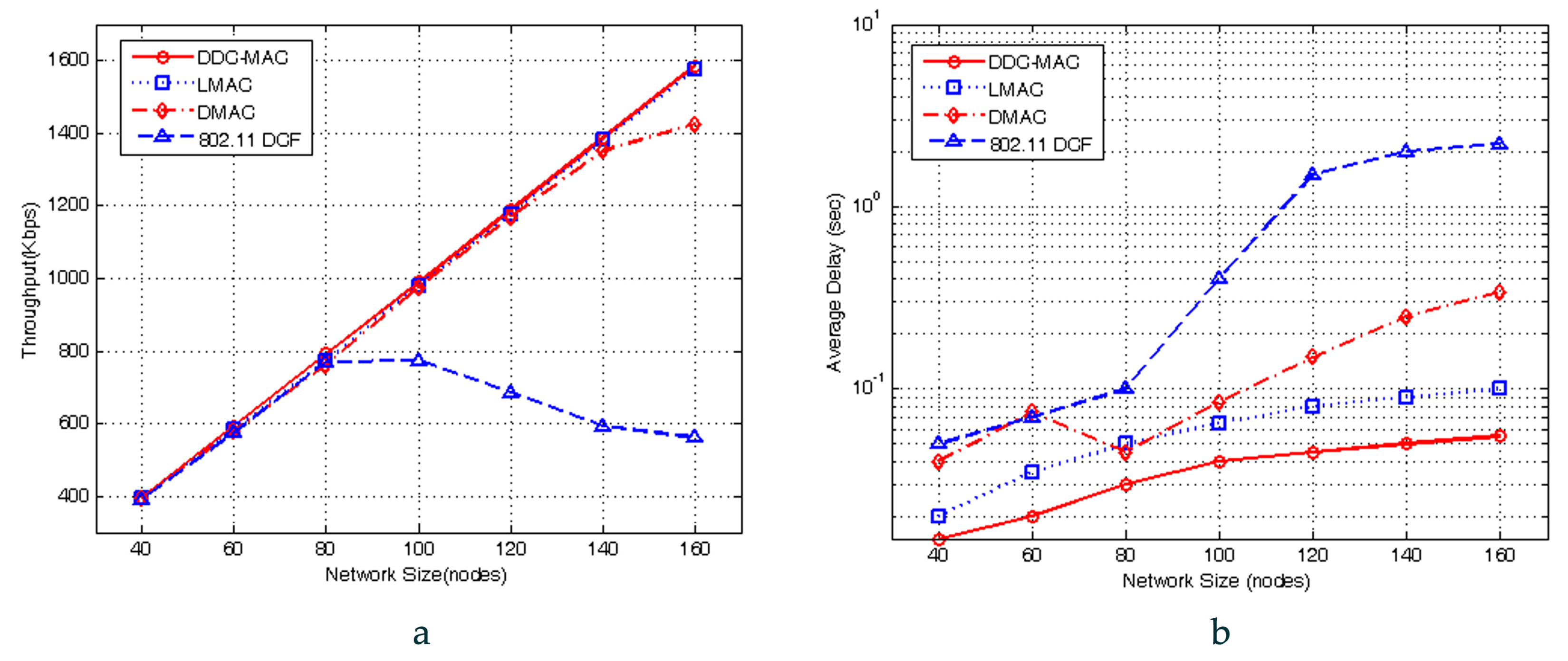
This subsection evaluates the saturated throughput (ST) and average delay (AD) of DDC-MAC in PC scenario; the results are compared to the typical schedule-based MAC protocol (i.e., LMAC) and the typical contention-based MAC protocol (i.e., IEEE802.11b DCF, DMAC). The packet arrival rate (PAR) of each node is 20 packets/sec. To consider the impacts of fading effects and the influence of beam direction on saturation, the transmission rate was down-graded with the probabilities and . Thus, we set and , and increase the number of nodes from 40 to 160; the analysis of saturated throughput can be validated by observing the aggregate uplink throughput.
Figure 9a compares the ST performance of four protocols with PC service. The results indicate that the throughputs of DDC-MAC, LMAC, and DMAC increase linearly with the increase of network size (). The reason is that LMAC and DDC-MAC adopt conflict-free TDMA schedule, while DMAC adopts a simple duty-cycle-based operation. Meanwhile, 802.11 DCF obtains the worst throughput performance. When , the throughput of 802.11 DCF stays at a constant value ( kbps), and then decreases slowly when . The reason for this is that the increasing pairs aggravate the contentions and collisions, and the capacity for communications is in saturation, i.e., 570 kbps when . Furthermore, these results can validate the analysis of saturation, which is presented in Section 5.2.
Figure 9b depicts the average latencies under PC service. It is clear that the average delay of DDC-MAC, LMAC, and DMAC increases slowly when the network size is in , whereas the performance of 802.11 fluctuates due to its omni-directional transmission and CSMA-based mechanism. In addition, LMAC and DDC-MAC achieve a similar inclination as DMAC, but their average delays are much lower, as they enjoy the benefits of a TDMA-based mechanism, thus guaranteeing non-collision transmission. Moreover, DDC-MAC outperforms LMAC because its traffic period is shortened by cluster-based topology, and its average delay is lower than 55 ms when .
6.2.2. Saturated Throughput and Delay in 1-Hop on-Demand Communication
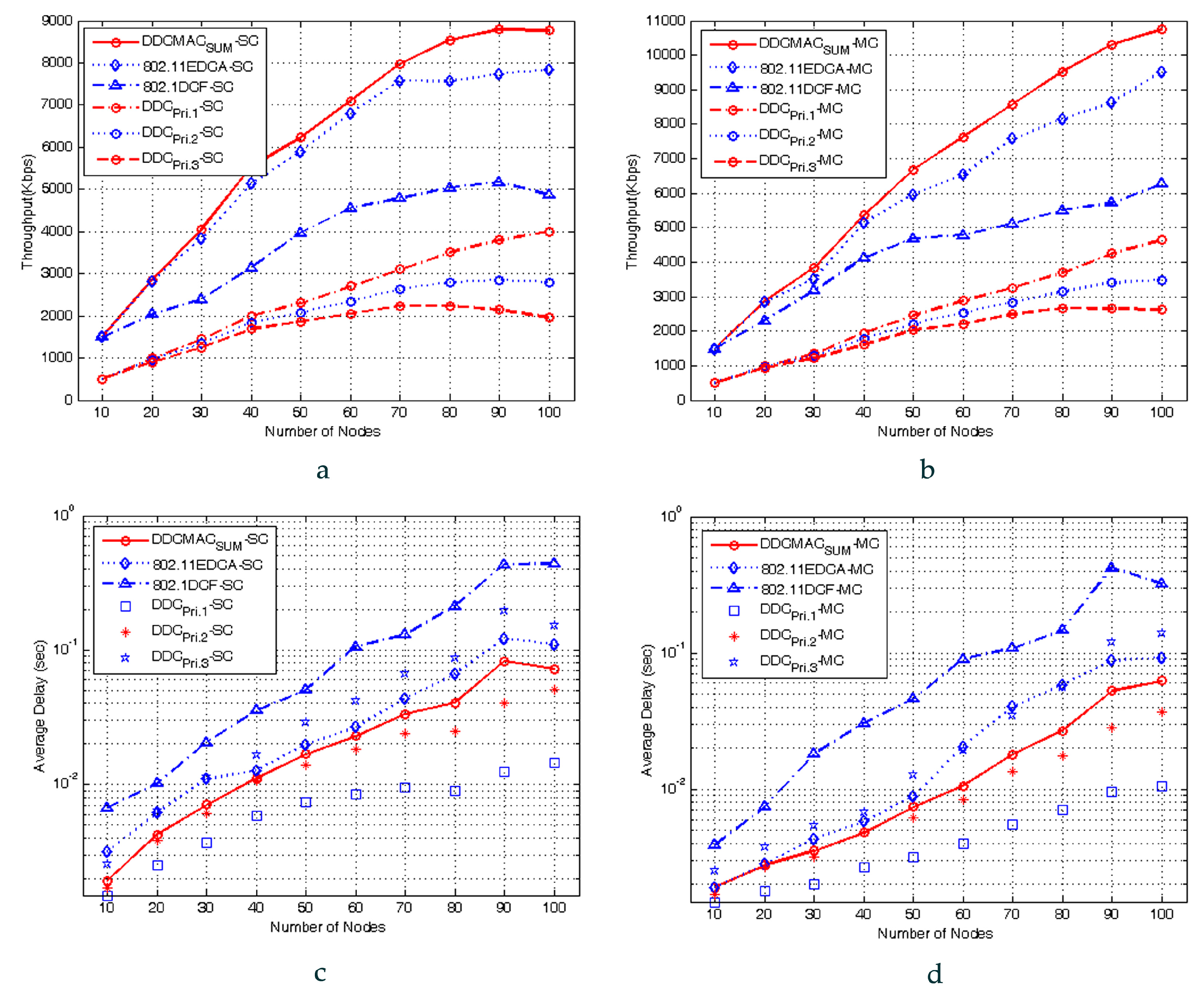
This subsection evaluates the ST and AD performance of DDC-MAC in 1-hop OC mode under single-channel (SC) and multi-channel (MC) environments, respectively. We assume that each node in 802.11 DCF is equipped with an omni-directional antenna, and the node in 802.11 EDCA and DDC-MAC is equipped with the adaptive antenna array proposed in Section 3.2. To verify the proposed Diffserv mechanism, the results of different service priorities, namely Pri.S1, Pri.S2, and Pri.S3, are depicted in Figure 10. As shown in the results, in general, the service with higher service priority can achieve the performance of throughput and average delay superior to those of lower priority services (Pri.S1 > Pri.S2 > Pri.S3), whereas the performances in MC environments outperform those of SC environments.
Figure 10a,b depicts the ST comparison of three protocols under SC and MC environments. In Figure 10a, the throughput of 802.11 DCF increases slowly due to its OT transmission mode, and thus results in a high probability of contentions and collisions. Meanwhile, 802.11 EDCA and DDC-MAC explore the opportunities of spatial reuse effectively by using adaptive antenna array; thus, their throughputs increase along with the number of nodes. Finally, compared to 802.11 DCF, 802.11 EDCA and DDC-MAC achieve approximately 45% and 70% of throughput gain, respectively. When , the throughput growth of 802.11 EDCA and DDC-MAC decelerates and holds a constant value when ( kbps, kbps). In a SC environment, DDC-MAC cannot use ACBS for distributing communicating nodes over multiple channels; thus, its throughput performance is similar to 802.11 EDCA. Figure 10b depicts the ST of three protocols in an MC environment, in which 802.11 DCF and 802.11 EDCA use a random channel selection policy, and the proposed DDC-MAC uses an ACBS policy. The throughputs of three protocols are similar when the number of pairs is few (). However, when the number of pairs increases (), the throughputs of 802.11 EDCA and DDC-MAC are superior to that of 802.11 DCF because of the exploitation of spatial reuse opportunities by means of directional antenna and ACBS mechanisms. Moreover, DDC-MAC outperforms 802.11 EDCA because its traffic congestion is alleviated by the DMDG-based cluster protocol. The ST performance in an MC environment outperforms that of SC environment by 20% to 32%.
Figure 10c,d describes the impact of the number of nodes on packet delay. The packet delay is measured by the duration from the memory buffer to the time when the packet has been sent successfully. Figure 10c shows the comparison of the three protocols in SC environment. Generally, the AD increases along with the number of nodes, owing to increasing of contentions and collisions. The 802.11 DCF adopts an omni-directional antenna, which blocks parallel communications, and thus its packet delay increases the fastest. Meanwhile, the AD of 802.11 EDCA and DDC-MAC is compensated for by exploiting spatial reuse opportunities by directional antennas. Compared to Figure 10c, the performance in multi-channel environments is superior in every respect, with the average delay decreasing by approximately 40–50%. As shown in Figure 10d, the ADs of three protocols are constant (about 2.5 ms) when . Since there are three data channels in use, the probability of collision and retransmission is low when is small. However, the AD of 802.11 DCF increases rapidly with the increase of , and reaches 0.42 s when . Meanwhile, the AD of 802.11 EDCA and DDC-MAC increases slower than 802.11 DCF, and keeps a constant value when (62.3 ms for DDC-MAC, 92.6 ms for 802.11 EDCA).
6.2.3. Performance Analysis in 2-Hop Optimal Relay Communication
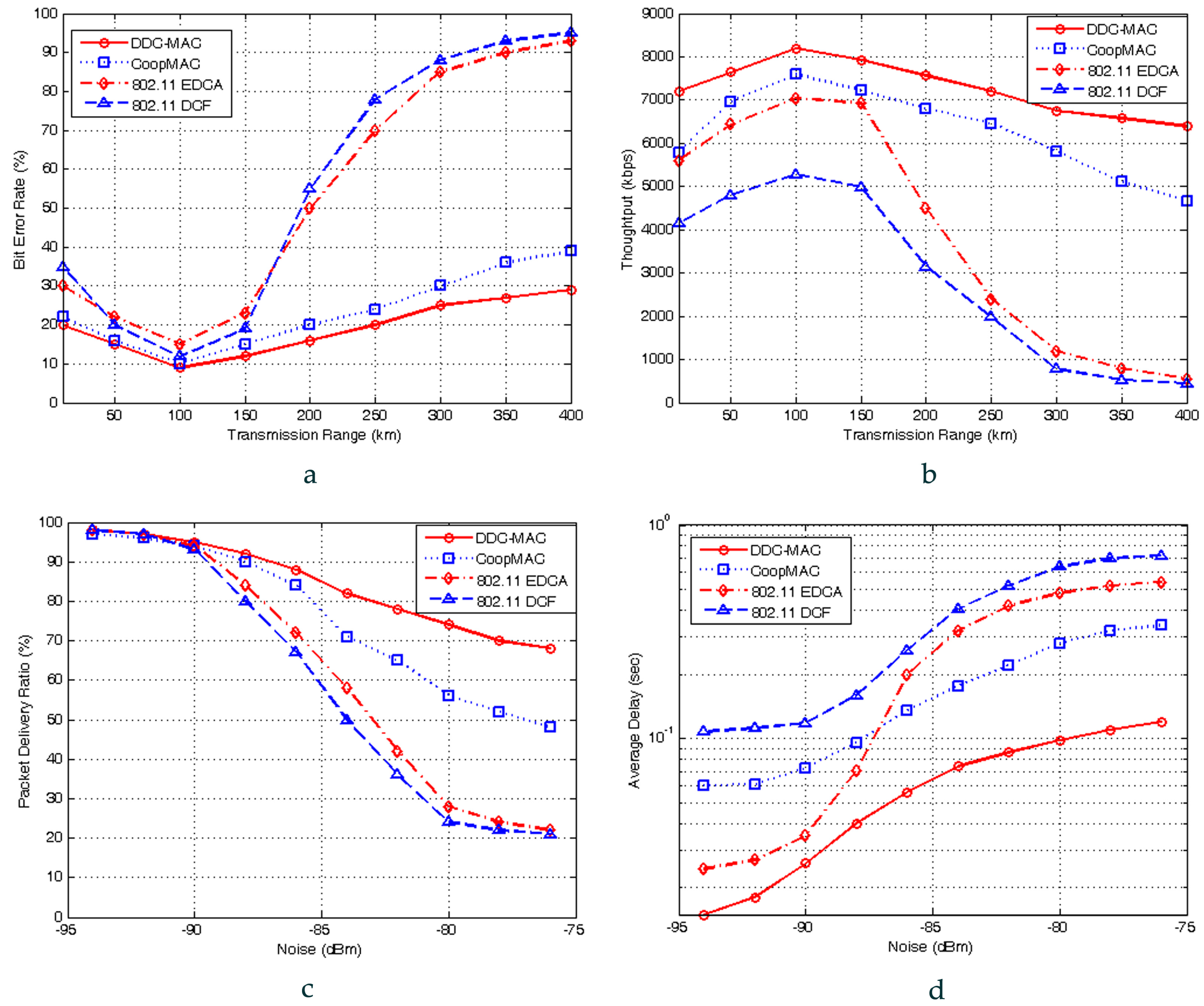
In this subsection, we present a numerical analysis for the performance with the increasing transmission range and the degrading link quality. The number of nodes is set to 70.
Figure 11a,b depicts the impact of transmission distance on bit error ratio (BER) and throughput performance. It is observed that 802.11 EDCA, CoopMAC, and DDC-MAC have similar BER and throughput when the distance is closer than 150 km. When the distance exceeds 150 km, the performance of 802.11 EDCA and 802.11 DCF degrades sharply due to the deterioration of link quality and retransmission. When the distance is 400 km, the BER of 802.11 EDCA and 802.11 DCF all keep constant values to 95%, and their throughputs keep constant values to 530 kbps, while CoopMAC and DDC-MAC performs better than 802.11 DCF and 802.11 EDCA due to the benefits of the cooperative relay mechanism. Furthermore, DDC-MAC outperforms CoopMAC due to the optimal relay mechanism and the ACBS mechanism. When the transmission range is 400 km, the bit error ratios of CoopMAC and DDC-MAC keep constant values of 38.5% and 29.7%, and the throughputs are 4750 kbps and 6430 kbps, respectively.
Figure 11c,d shows the PDR and AD performance of four protocols with environmental noise level varied from −94 dBm to −76 dBm. When the channel condition is good (Noise < −90 dBm), the PDR of four protocols is higher than 94%, the AD is lower than 0.1 s, and degrades slowly. When the noise level increases (Noise > −90 dBm), the performance of 802.11 EDCA and 802.11 DCF degrades sharply due to the deterioration of link quality. When Noise = −75 dBm, the PDR of 802.11 EDCA and 802.11 DCF is 21%, and the AD is 0.54 s and 0.72 s, respectively. CoopMAC and DDC-MAC outperforms 802.11 DCF and 802.11 EDCA due to the benefits from channel selection policy, and DDC-MAC outperforms CoopMAC due to the optimal relay mechanism and its adaptive antenna array. When Noise = −75 dBm, the PDRs of CoopMAC and DDC-MAC are 48.1% and 68.3%, and the AD is 0.33 s and 0.12 s, respectively.
7. Conclusions and Future Work
In this paper, we have proposed a novel approach, namely a DiffServ-based dynamic cooperative MAC (DDC-MAC) protocol, to realize QoS media access control for the wireless network with the unique features in terms of large-range transmission, high dynamic topology, three-dimensional monitor region, and heterogeneous services.
Its performance is analyzed by Markov chain-based modeling, and validated by ns-2 simulations. Both theoretical analysis and simulation experiments show that DDC-MAC can leverage cooperative communications and exploit spatial and user diversities. Therefore, it outperforms the existing protocols under the same channel assumptions and network scenarios. DDC-MAC also provides extended service ranges and a robust wireless communication link in NC-NET.
As future research, we will pursue the following directions: (i) investigate protocols integrated with routing protocols; (ii) explore the performance with different slot intervals, prediction window and prediction techniques, and (iii) extend DDC-MAC to other NC-NET with different topologies and mobility models.
Acknowledgments
This work was supported in part by the National Natural Science Foundation of China under Grant No. 61473306, and partly by the Defense Advanced Research Project of China under Grant No. 9140A09040614JB14001.
Author Contributions
Chao Gao and Guorong Zhao conceived and designed the MAC protocol; Bin Zeng analyzed and developed algorithm; Jianhua Lu performed the experiments; Chao Gao wrote the paper.
Conflicts of Interest
The authors declare no conflict of interest.
References
- Bekmezci, I.; Sahingoz, O.; Temel, S. Flying Ad-Hoc Networks (FANETs): A survey. Ad Hoc Netw. 2013, 11, 1254–1270. [Google Scholar] [CrossRef]
- Gao, C.; Zhao, G.; Pan, S. Distributed multi-weight data-gathering and aggregation protocol in fleet wireless sensor networks: Optimal and heuristic algorithms. Int. J. Intell. Eng. Syst. 2009, 2, 1–8. [Google Scholar] [CrossRef]
- Gao, C.; Zhao, G.; Lu, J.; Pan, S. A Grid-based Cooperative QoS Routing Protocol with Fading Memory Optimization for Navigation Carrier Ad Hoc Networks. Comput. Netw. 2015, 76, 294–316. [Google Scholar] [CrossRef]
- Gao, C.; Zhao, G.; Lu, J.; Pan, S. Decentralised Moving-Horizon State Estimation for a Class of Networked Spatial-Navigation Systems with Random Parametric Uncertainties and Communication Link Failures. IET Control Theory Appl. 2015, 9, 2666–2677. [Google Scholar] [CrossRef]
- Ko, Y.; Shankarkumar, V.; Vaidya, N. Medium access control protocols using directional antennas in ad hoc networks. In Proceedings of the Nineteenth Annual Joint Conference of the IEEE Computer and Communications Societies, Tel Aviv, Israel, 26–30 March 2000; pp. 13–21. [Google Scholar]
- IEEE 802.11 Working Group. Wireless LAN medium access control (MAC) and physical layer (PHY) specifications. In ANSI/IEEE Standard 802.11; IEEE 802.11 Working Group: Berlin, Germany, 1999. [Google Scholar]
- Yi, S.; ·Pei, Y.; ·Kalyanaraman, S.; Azimi-Sadjadi, B. How is the capacity of ad hoc networks improved with directional antennas. Wirel. Netw. 2007, 13, 635–648. [Google Scholar] [CrossRef]
- Collins, R. Tactical Targeting Network Technology (TTNT) Communicating at the Speed of Battle [EB/OL]. October 2010. Available online: http://www.rockwellcollins.com/content/pdf/pdf.7501.pdf (accessed on 15 October 2010).
- Alam, M.; Hussain, M.; Kwak, K. Neighbor initiated approach for avoiding deaf and hidden node problems in directional MAC protocol for ad-hoc networks. Wirel. Netw. 2013, 19, 933–943. [Google Scholar] [CrossRef]
- Sakakibara, K.; Taketsugu, J. A new IEEE 802.11 DCF utilizing freezing experiences in backoff interval and its saturation throughput. J. Commun. Netw. 2010, 12, 43–51. [Google Scholar]
- Huang, Z.; Shen, C.; Srisathapornphat, C.; Jaikaeo, C. A busy-tone based directional MAC protocol for ad hoc networks. In Proceedings of the Military Communications Conference (MILCOM 2002), Anaheim, CA, USA, 7–10 October 2002; pp. 1233–1238. [Google Scholar]
- Incel, O.; Hoesel, L.; Jansen, P.; Havinga, P. MC-LMAC: A multi-channel MAC protocol for wireless sensor networks. Ad Hoc Netw. 2011, 9, 73–94. [Google Scholar] [CrossRef]
- Hoesel, L. Sensors on Speaking Terms: Schedule-Based Medium Access Control Protocols for Wireless Sensor Networks. Ph.D. Thesis, University of Twente, Enschede, The Netherlands, June 2007. [Google Scholar]
- Akyildiz, I.; Melodia, T.; Chowdhury, K. A survey on wireless multimedia sensor networks. Comput. Netw. 2007, 51, 921–960. [Google Scholar] [CrossRef]
- Lazarou, G.; Li, J.; Picone, J. A cluster-based power-efficient MAC scheme for event-driven sensing applications. Ad Hoc Netw. 2007, 5, 1017–1030. [Google Scholar] [CrossRef]
- Boukerche, A.; Dash, T. Performance evaluation of a generalized hybrid TDMA/CDMA protocol for wireless multimedia with QoS adaptations. Comput. Commun. 2005, 28, 1468–1480. [Google Scholar] [CrossRef]
- Saxena, N.; Roy, A.; Shin, J. Dynamic duty cycle and adaptive contention window based QoS-MAC protocol for wireless multimedia sensor networks. Comput. Netw. 2008, 52, 2532–2542. [Google Scholar] [CrossRef]
- Yigitel, M.; Incel, O.; Ersoy, C. Design and implementation of a QoS-aware MAC protocol for Wireless Multimedia Sensor Networks. Comput. Commun. 2011, 34, 1991–2001. [Google Scholar] [CrossRef]
- Liu, P.; Tao, Z.; NaNarayana, S.; Korakis, T.; Panwar, S. CoopMAC: A cooperative MAC for wireless LANs. IEEE J. Sel. Areas Commun. 2007, 25, 340–354. [Google Scholar] [CrossRef]
- Moh, S.; Yu, C. A cooperative diversity-based robust MAC protocol in wireless ad hoc networks. IEEE Trans. Parallel Distrib. Syst. 2011, 22, 353–363. [Google Scholar] [CrossRef]
- An, D.; Woo, H.; Yoon, H.; Yeom, I. Enhanced Cooperative Communication MAC for Mobile Wireless Networks. Comput. Netw. 2013, 57, 99–116. [Google Scholar] [CrossRef]
- Zhang, X.; Guo, L.; Wei, X. An energy-balanced cooperative MAC protocol based on opportunistic relaying in MANETs. Comput. Electr. Eng. 2013, 39, 1894–1904. [Google Scholar] [CrossRef]
- Khalid, M.; Wang, Y.; Ra, I.; Sankar, R. Two-Relay-Based Cooperative MAC Protocol for Wireless Ad hoc Networks. IEEE Trans. Veh. Technol. 2011, 60, 3361–3373. [Google Scholar] [CrossRef]
- Antonopoulos, A.; Skianis, C.; Verikoukis, C. Network coding-based cooperative ARQ scheme for VANETs. J. Netw. Comput. Appl. 2013, 36, 1001–1007. [Google Scholar] [CrossRef]
- Wang, X.; Zhang, X.; Chen, G.; Zhang, Q. Opportunistic cooperation in low duty cycle wireless sensor networks. In Proceedings of the IEEE International Conference on Communications (ICC), Cape Town, South Africa, 23–27 May 2010. [Google Scholar]
- Xie, K.; He, S.; Zhang, D.; Wen, J.; Lloret, J. Busy tone-based channel access control for cooperative communication. Trans. Emerg. Telecommun. Technol. 2015, 26, 1173–1188. [Google Scholar] [CrossRef]
- Chen, Y.; Liu, J.; Jiang, X. Throughput analysis in mobile ad hoc networks with directional antennas. Ad Hoc Netw. 2013, 11, 1122–1135. [Google Scholar] [CrossRef]
- Besse, F.; Garcia, F.; Pirovano, A. Wireless Ad Hoc Networks Access for Aeronautical Communications. In Proceedings of the 28th AIAA International Communications Satellite Systems Conference, Anaheim, CA, USA, 30 August–2 September 2010; pp. 1–15. [Google Scholar]
- Bianchi, G. Performance analysis of the IEEE 802.11 distributed coordination function. IEEE J. Sel. Areas Commun. 2000, 18, 535–547. [Google Scholar] [CrossRef]
- He, X.; Kumar, R.; Mu, L.; Gjøsæter, T.; Li, F. Formal verification of a Cooperative Automatic Repeat reQuest MAC protocol. Comput. Stand. Interfaces 2012, 34, 343–354. [Google Scholar] [CrossRef] [Green Version]
Figure 1.
Typical illustration of networked UAVs based on NC-NET.

Figure 2.
Transmission modes with adaptive antenna.

Figure 3.
Round structure in adaptive TDMA schedule.

Figure 4.
State diagram of Scenarios 1 and 2 in the negotiation phase.
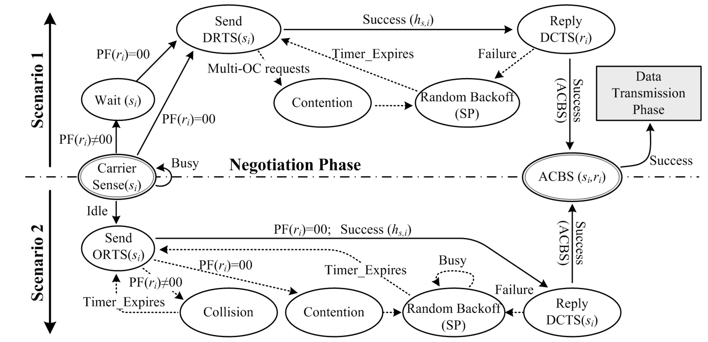
Figure 5.
Schematic diagram of data transmission phase.
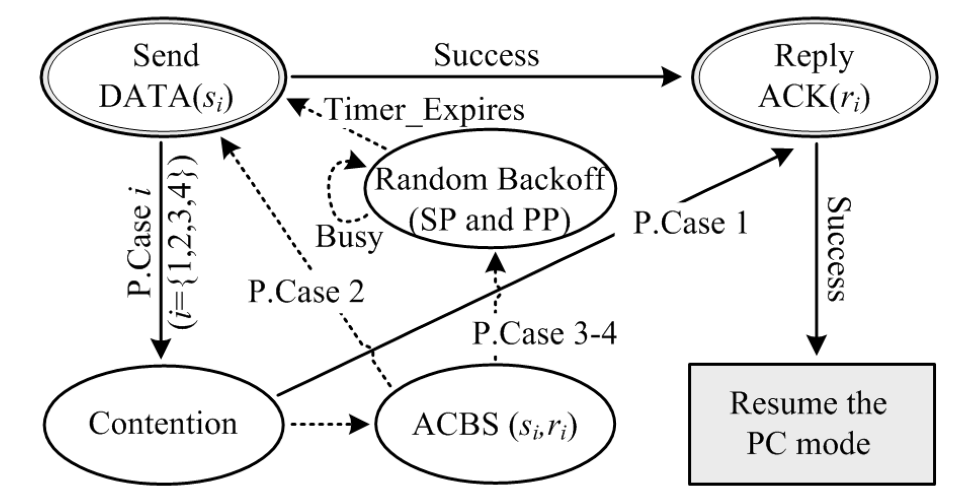
Figure 6.
Potential problematic scenarios in DDC-MAC. (a) problematic scenario of deafness and hidden terminal problem; (b) solutions of deafness and hidden terminal problem by DDC-MAC; (c) problematic scenario of interference and congestion problem; (d) solutions of interference and congestion problem by DDC-MAC.
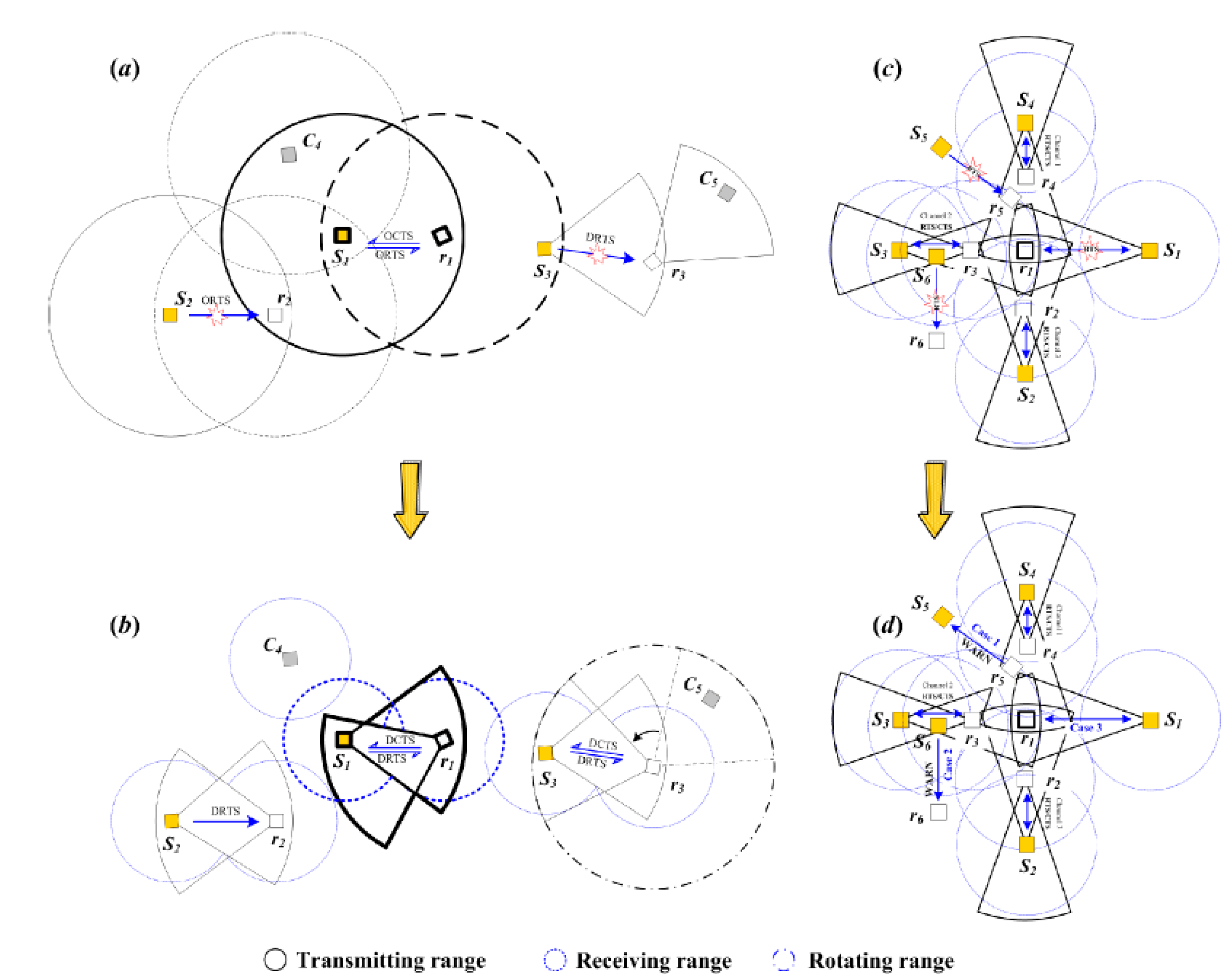
Figure 7.
Searching probability region in Scenario 3.
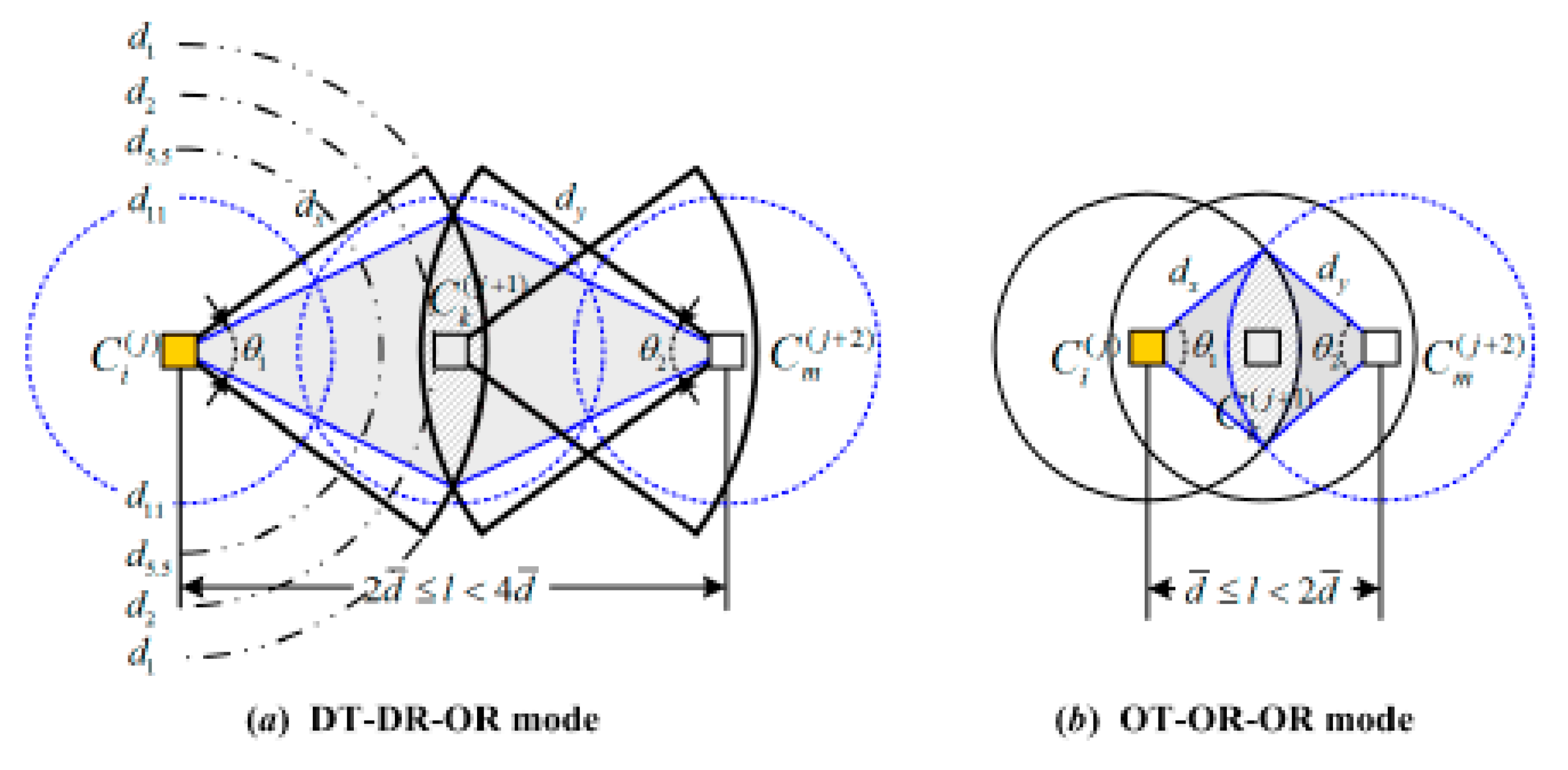
Figure 8.
Initial network topologies with 160 nodes.
Figure 9.
Performance of MAC protocols in PC mode: (a) Throughput; (b) End-to-end average delay.

Figure 10.
Throughput and average delay performances versus number of nodes in 1-hop OC mode. (a) Throughput in single-channel environment; (b) Throughput in multi-channel environment; (c) average delay in single-channel environment; (d) average delay in multi-channel environment.
Figure 10.
Throughput and average delay performances versus number of nodes in 1-hop OC mode. (a) Throughput in single-channel environment; (b) Throughput in multi-channel environment; (c) average delay in single-channel environment; (d) average delay in multi-channel environment.

Figure 11.
Impacts of transmission range and link quality on MAC performances with 2-hop optimal relay. (a) Transmission distance vs. bit error ratio; (b) transmission distance vs. throughput; (c) packet delivery ratio vs. link quality; (d) average delay vs. link quality.
Figure 11.
Impacts of transmission range and link quality on MAC performances with 2-hop optimal relay. (a) Transmission distance vs. bit error ratio; (b) transmission distance vs. throughput; (c) packet delivery ratio vs. link quality; (d) average delay vs. link quality.


Table 1.
Propagation parameters in long-range transmission.
| Free Space Losses (dB) | 147.33 | 143.80 | 141.32 | 137.78 |
|---|---|---|---|---|
| Frequency (GHz) | 1 | 1 | 1 | 1 |
| Distance (km) | 555 | 370 | 278 | 185 |
| Data Rate | 220 kbit/s | 500 kbit/s | 1 Mbps | 2 Mbit/s |
Table 2.
Multi-rate setting for NC-NET ().
| Serial No. | Data Rate | Threshold | Range |
|---|---|---|---|
| 1 | 1 Mbit/s | −97 dBm | 278 km |
| 2 | 2 Mbit/s | −94 dBm | 185 km |
| 3 | 5.5 Mbit/s | −88 dBm | 92.5 km |
| 4 | 11 Mbit/s | −83 dBm | 50 km |
Table 3.
Analytical parameter settings.
| Parameters | Values | Parameters | Values |
|---|---|---|---|
| Data rate (Mbps) | {1, 2, 5.5, 11} | CW for Pri.S3 | CWmin = 32, CWmax = 1024 |
| SIFS | 0.01 ms | ACK | 14 bytes |
| DIFS | 0.02 ms | DATA packet | 512 bytes |
| ACK time | 0.02 ms | MAC header | 34 bytes |
| SNR threshold | 15 dB | PHY header | 24 bytes |
| RTS | 20 bytes | Tx power (dBm) | 32(omni), 38(dir) |
| CTS | 14 bytes | Cluster Protocol | DMDG [2] |
| CW for Pri.S1 | CWmin = 8, CWmax = 16 | Routing Protocol | FMCQR [3] |
| CW for Pri.S2 | CWmin = 16, CWmax = 32 | — | — |
© 2017 by the authors. Licensee MDPI, Basel, Switzerland. This article is an open access article distributed under the terms and conditions of the Creative Commons Attribution (CC BY) license (http://creativecommons.org/licenses/by/4.0/).
Share and Cite
MDPI and ACS Style
Gao, C.; Zeng, B.; Lu, J.; Zhao, G. Dynamic Cooperative MAC Protocol for Navigation Carrier Ad Hoc Networks: A DiffServ-Based Approach. J. Sens. Actuator Netw. 2017, 6, 14. https://doi.org/10.3390/jsan6030014
AMA Style
Gao C, Zeng B, Lu J, Zhao G. Dynamic Cooperative MAC Protocol for Navigation Carrier Ad Hoc Networks: A DiffServ-Based Approach. Journal of Sensor and Actuator Networks. 2017; 6(3):14. https://doi.org/10.3390/jsan6030014
Chicago/Turabian StyleGao, Chao, Bin Zeng, Jianhua Lu, and Guorong Zhao. 2017. "Dynamic Cooperative MAC Protocol for Navigation Carrier Ad Hoc Networks: A DiffServ-Based Approach" Journal of Sensor and Actuator Networks 6, no. 3: 14. https://doi.org/10.3390/jsan6030014
Note that from the first issue of 2016, this journal uses article numbers instead of page numbers. See further details here.