1. Introduction
Already implemented in Third Generation (3G) and Fourth Generation (4G) systems, Multiple-Input Multiple-Output (MIMO) techniques allow the transmission of multiple simultaneous data streams, leading to substantial capacity gains [
1,
2]. With the arrival of the Fifth Generation (5G), systems are expected to substantially increase their overall spectral efficiency, especially compared with current 4G Long-Term Evolution (LTE) systems [
3]. This will be achieved mainly by combining massive MIMO techniques, small cells and reduced frequency reuse factors (ideally aiming at universal frequency reuse) [
4]. Base Station (BS) cooperation systems are a logical approach to allow the implementation of a universal frequency reuse scenario [
5]. In the uplink transmission of BS cooperation schemes, MTs in adjacent cells can share the same physical channel and the signals between different MTs and BSs are collected and processed by a Central Processing Unit (CPU), which performs the user separation and/or interference mitigation.
It is well known that block transmission techniques, combined with frequency-domain processing, are suitable for broadband wireless systems. These techniques include Orthogonal Frequency Division Multiplexing (OFDM) [
6] and Single-Carrier with Frequency Domain Equalization (SC-FDE) [
7], which have similar overall signal processing requirements and achievable performance. Due to receiver complexity in SC-FDE and since the envelope fluctuations of single-carrier signals are much lower than the ones in OFDM, SC-FDE and OFDM are preferable for the uplink and downlink transmissions [
8], respectively. The performance of SC-FDE can be further improved if linear FDEs are replaced by the powerful Iterative Block Decision Feedback Equalization (IB-DFE) schemes [
7]. In fact, the performance of IB-DFE schemes can be close to the Matched Filter Bound (MFB) in many scenarios [
7]. For this reason, the IB-DFE concept was already extended to a wide range of scenarios, including Layered Space-Time (LST) schemes [
9], Space Division Multiple Access (SDMA) [
10], Code Division Multiple Access (CDMA) schemes [
11], BS cooperation schemes [
5], as well as other MIMO schemes.
In this paper, we consider SC-FDE schemes combined with MIMO architectures with
P transmitting and
R receiving antennas, with different overall noise characteristics on the different receiver branches, which can be a result of different noise levels and/or nonlinear effects at the receiver side (e.g., quantization effects [
12]). The receivers are based on the IB-DFE and take into account the statistical characteristics of the overall noise at the detection level. The typical MIMO receiver requires the inversion of
matrices, which might not be efficient when
. We present an efficient method for computing the receiver parameters that requires the inversion of
matrices, which is particularly interesting for the case where
. This method can be applied to any MIMO system combined with IB-DFE-based receivers. Furthermore, in this paper, we present an implementation scheme with low resolution Analog-to-Digital Converters (ADCs). Even though it is possible to cheaply employ ADC solutions, it still can have a significant complexity load, especially for massive MIMO systems. For this reason, a substantial work on massive MIMO with low resolution quantizers is presented in [
13,
14,
15]. Moreover, the use of reduced resolution ADCs allows an advantage for BS cooperation systems, which can be considered as distributed MIMO systems where the antennas are placed in different cells [
5,
12]. Consequently, it is possible to reduce the signaling requirements between the receiving antennas and central unit that performs the multi-user separation, which is done through the backhaul, which has limited capacity.
This work is organized as follows: in
Section 2, we describe the cellular architecture considered in this paper, and
Section 3 is concerned with the receiver design and the signals’ detection. A set of performance results is presented in
Section 4, and
Section 5 concludes the paper.
In this paper, we adopt the following notations: bold upper case letters denote matrices or vectors; denote the identity matrix; , and denote the complex conjugate, transpose and Hermitian (complex conjugate transpose) of , respectively. In general, lower case letters denote time-domain variables, and upper case letters denote frequency-domain variables; , and denote sample, “hard decision” and “soft decision” estimates of x, respectively. The expectation of x is denoted by .
2. System Characterization
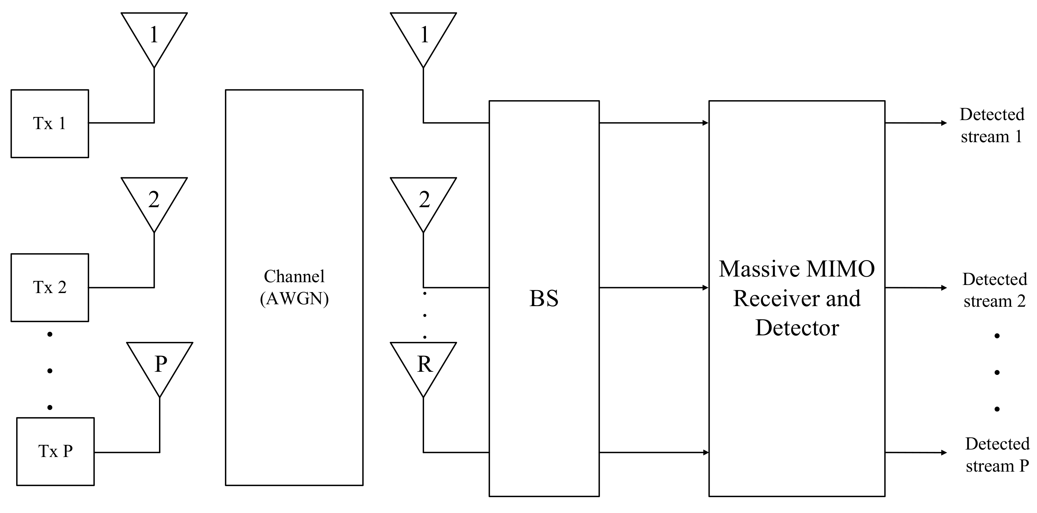
The system is characterized by a MIMO communication scheme, where
P independent data streams are sent to
R receiving antennas, as illustrated in
Figure 1.
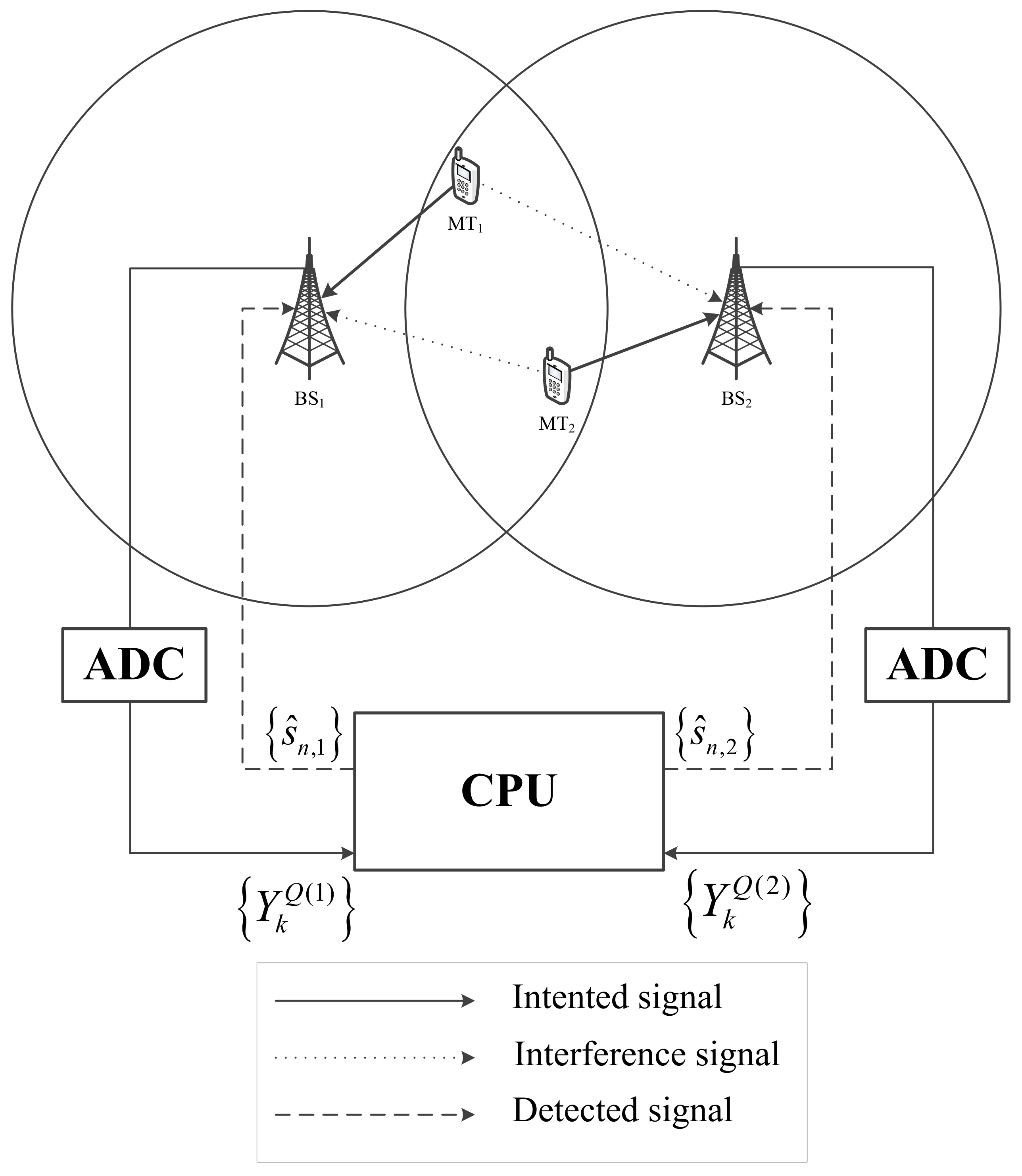
With the purpose of performing the multi-streaming detection and/or separation, this scheme can be framed into BS cooperation [
5] or other MIMO systems, as shown in
Figure 2 and
Figure 3, respectively.
In BS cooperation systems, P MTs share the same physical channel and transmit to R separate BSs. Instead of having one MT assigned exclusively to a given BS and the signals from other MTs being considered interference, in BS cooperation systems, the transmission is performed in the same frequency, and the combined signals are detected by a Central Processing Unit (CPU).
On the other hand, in conventional MIMO or massive MIMO systems, one can have P multiple streams transmitted to a multi-reception array with up to R antennas. In general, we have , unless we have an overloaded system, and both R and P can be much greater than one, namely in massive MIMO schemes.
In the adopted transmission scheme, the communication between the
P transmitting and
R receiving antennas is subject to frequency-selective multipath channels. Each transmission link employs an
N-symbol-sized SC-FDE block modulation scheme with an appropriate length Cyclic Prefix (CP) appended to each block. After the removal of the samples associated with the CP, the useful time-domain received data stream at the
r-th antenna can be expressed by:
with ⊛ denoting the cyclic convolution concerning the index
n.
indicates the Channel Impulse Response (CIR) between
p and
r for the
n-th time-domain element. The data symbol
is selected from a constellation scheme according to a given mapping rule such as Quadrature Phase Shift Keying (QPSK) with Gray mapping. The Additive White Gaussian Noise (AWGN) component is denoted by
, and
corresponds to a weighting parameter that accounts for the combined effects of power control and propagation loss, with the average received power associated with the
p-th MT at the
r-th BS corresponding to
. Moreover, thanks to the CP, the frequency-domain version of (
1) can be expressed as:
where
is the Discrete Fourier Transform (DFT) of the useful time-domain received block
(
) and
corresponds to the DFT of the time-domain data block
that is associated with the
p-th transmitting antenna
.
corresponds to the frequency-domain noise component associated with the
r-th antenna and the
k-th frequency and:
where
denotes the channel frequency response between the
p-th MT and the
r-th BS, for the
k-th frequency, where we have a normalized channel frequency response, so as
.
The detection blocks associated with each receiving antenna can have nonlinear devices, namely those associated with the quantization effects in low resolution ADCs [
16,
17]. Let us admit a scenario where the received data streams at each reception branch
r passes through an ADC, being sampled and quantized before the multi-stream detection is performed. Let us admit a scenario where the
r-th received time-domain data stream passes through an ADC. At the ADC output, the
n-th time-domain sample associated with the
r-th stream can be expressed as:
where
indicates the variance of the input signal. Furthermore,
denotes the quantization characteristics (or other nonlinear characteristic). In this paper, we consider a uniform “mid-rise” quantizer with a normalized saturation level of
and
m bits of resolution for the real and imaginary parts of a given quantized sample. Since we are considering severely time-dispersive channels with rich multipath propagation environment (the typical channel conditions in SC-FDE schemes), the received time-domain samples
can be accounted for as samples of a zero-mean complex Gaussian process, i.e.,
, with:
where:
and:
correspond to the symbol’s and noise variance, respectively. According to Bussgang’s theorem [
18], the Gaussian nature of
allows the quantized signals to be decomposed as the sum of uncorrelated useful and distortion terms, which leads to:
with
denoting the quantization noise term. The
parameter is a constant that depends only on the nonlinear characteristic and is given by:
In the frequency-domain, the sample associated with the quantized version of the signal
corresponds to:
which is the DFT of the time-domain signal
.
accounts for the global noise from the transmitted and quantized signals. The statistical characterization of
can be done as described in [
12]. Essentially,
is approximately complex Gaussian with zero mean and variance
, which is a function of
r and
k. The exact computation of
can be obtained using the method of [
12].
When the combined signals from all
P and
R antennas are taken into account, (
10) can be expressed in a matrix format, given by:
where
,
and
are column vectors of size
and
is a column vector of size
. Furthermore, the channel associated with the
k-th frequency component is represented by the
matrix:
with
.
3. Multiuser Detection
The detection of the different signals that are received at a given antenna
r relies on an iterative scheme based on the IB-DFE concept [
19]. This method takes advantage of the symbol’s detection on the previous iteration to compute a more updated estimate of the transmitted data symbols associated with each link from the
p-th antenna. In the
i-th iteration, the set of estimated symbols
is the hard decisions of the time-domain detector output
, where
is a column vector of size
and is given by:
As part of the iterative DFE process,
and
are the feedforward and feedback coefficient matrices of size
and
, respectively, expressed as:
and:
is a -sized column vector given by , where block is the DFT of the block of time-domain average values conditioned to the detector output .
In order to obtain the optimum coefficients
and
, which at a given iteration define the state of the detector, the Minimum Mean Squared Error (MMSE) criterion is followed. At each subcarrier
k and each data stream
p the MSE on the frequency-domain samples
corresponds to:
where its minimization is conditioned to:
with
indicating the average overall channel frequency response. Applying the gradient for the Lagrange function as:
the optimum coefficients
and
are given by:
and:
(see the details in [
5]), with
corresponding to a diagonal matrix defined as:
and
selected to ensure that
, in order to have a normalized FDE with
. In addition,
and
represent the variance of the real and imaginary parts of the channel noise and data sample components, respectively. This method for the multiuser detection requires inverting matrices of size
, which can be inefficient, namely in BS cooperation schemes or massive MIMO systems with fewer users. Since in these cases, the relation between transmitting and receiving antennas is
, then a method of inverting matrices of size
instead of
is desirable. For this purpose, we can consider the example of a matrix
, made of invertible blocks with appropriate dimensions, and its inverse
as:
with
and
being diagonal matrices (
indicates an identity matrix). It can be shown that
and
correspond to:
and:
respectively. Furthermore, from (
23), we have:
and from (
24):
From (
25) and (
26), we can say that:
Considering that:
and:
then (
27) can be expressed as:
Then, coefficient
given by (
19) can also be expressed as:
which requires an inversion of a
size matrix. Moreover, since
is a diagonal matrix, we have:
4. Performance Results
This section presents a set of Bit Error Rate (BER) performance results regarding the considered system. The channels have multipath propagation effects, making them frequency-selective. We assume 64 multipath components (similar results were observed for other channels, provided that we have strong multipath effects). We also assume uncorrelated Rayleigh fading on the different multipath components and for the different links between transmit and receive antennas, which are assumed to have low directivity. Perfect synchronization and channel estimation are assumed. The main conclusions apply for other channels, provided that we have rich multipath propagation. Although we are assuming a static channel, with perfect channel estimation and synchronization, the main conclusions of this paper are still valid for time-varying channels and/or in the presence of estimation errors. All the different
P transmitted streams associated with each receiving antenna
r assume that
dB. The concern about the ADC effects considers
m bits of resolution with a normalized saturation level of
. In the obtainment of the BER performance results, the detection process involves the computation of the
coefficient, in which the results from either Equations (
19) or (
31) are indistinguishable. Furthermore, we only show Iterations 1, 2 and 4, since the third iterations does not add relevant information. Lastly, all the performance results are compared with the MFB.
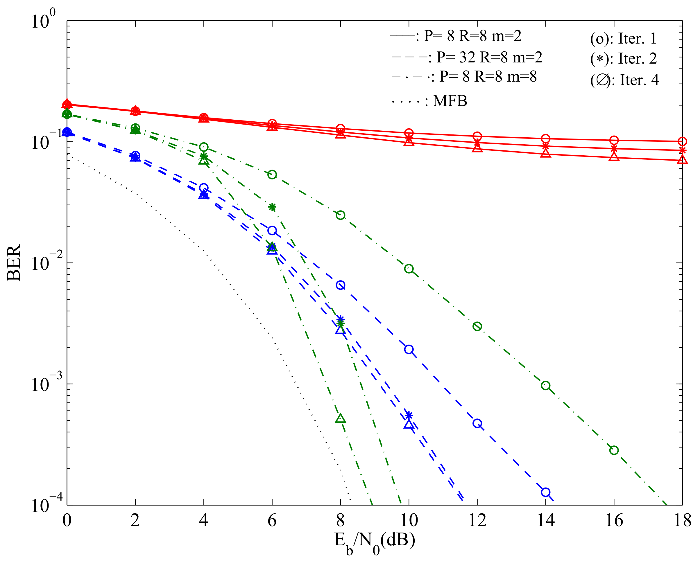
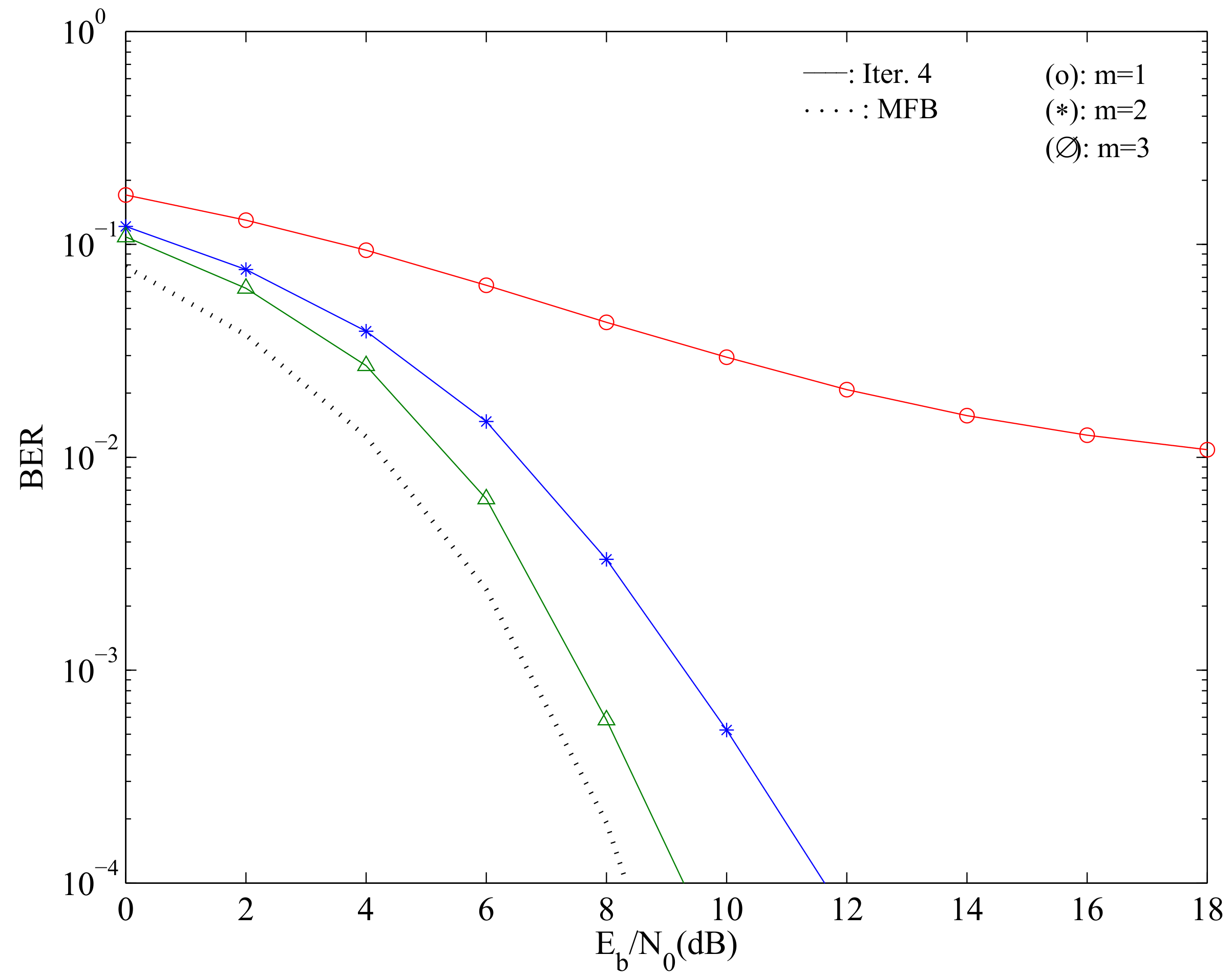
Figure 4 depicts the system’s average BER performance considering
with
and
bits of resolution and different values of
R.
From the figure, it can be seen that when , and , we have high error floors. However, performing iterations for the cancellation of the residual interference allows one to improve the system’s BER. These performance improvements are noticeable for large values of R, provided that P is fixed. In fact, when and , the system’s performance improves substantially, and the impact of the iterative feedback equalization is accentuated, although we observed that the performance stabilizes after the 4-th iteration. This is comparable to the case where we consider , and , which corresponds to the case where the effects from quantization are mostly negligible.
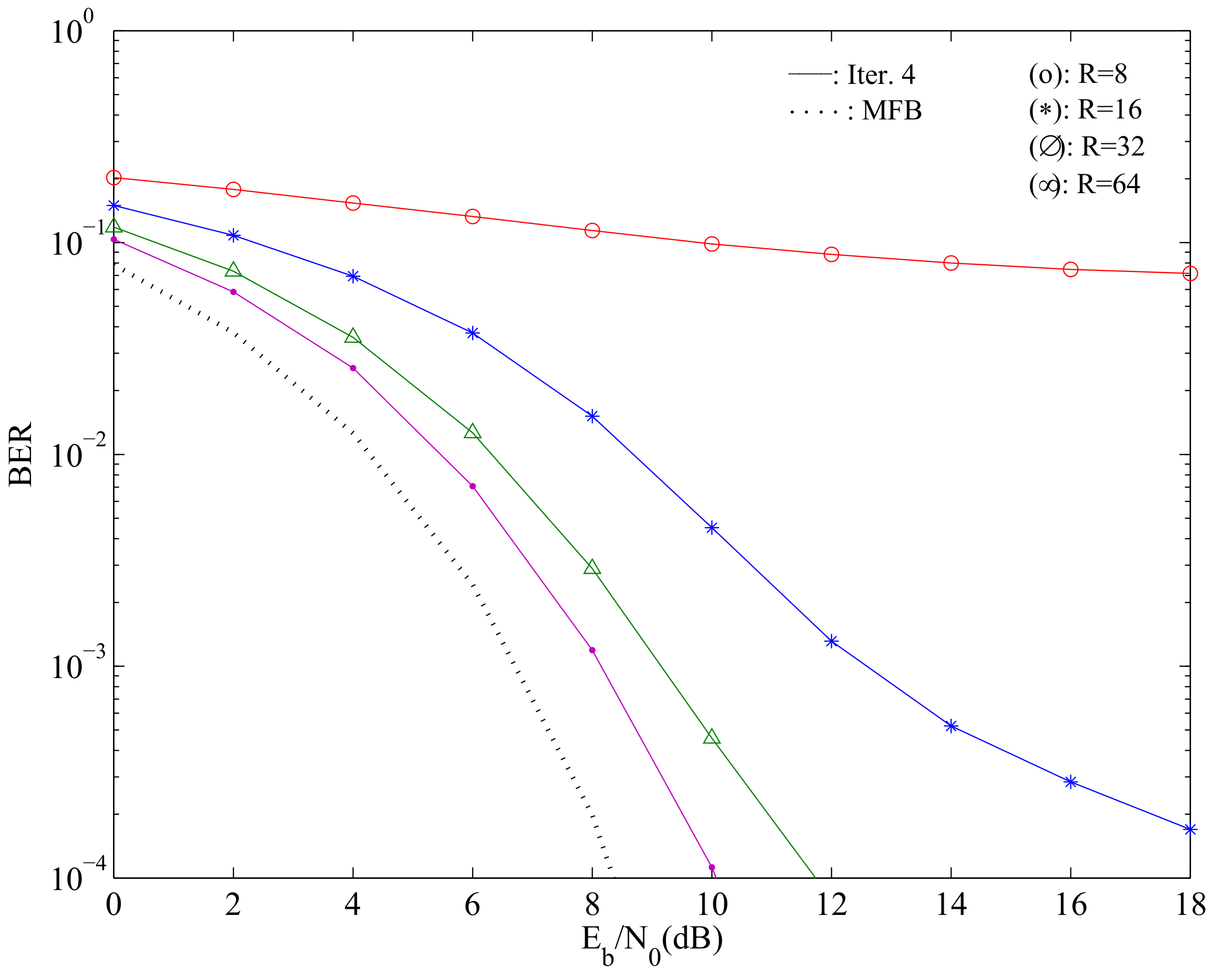
Figure 5 shows the average BER performance of the fourth iteration, considering
, ADCs with
bits of resolution and several values of
R.
From the depicted figure, one can note that increasing the number of receive antennas leads to performance improvements if the number of transmit antennas is fixed. In fact, although when there are high error floors due to the strong nonlinear distortion associated with the use of ADCs with only bits, when R increases and P is maintained fixed, the performance can even get closer to the single-user MFB.
Figure 6 illustrates the average BER performance of the fourth iteration, considering
,
and different values of
m.
As expected, it can be noted that lower resolutions lead to larger performance penalties. However, one can note that when , we can employ very low resolution ADCs without sacrificing the performance considerably. This reveals that in scenarios where , one can have energy-efficient, low complexity receive branches at the BS, enabling inexpensive, massive MIMO-ready BSs.
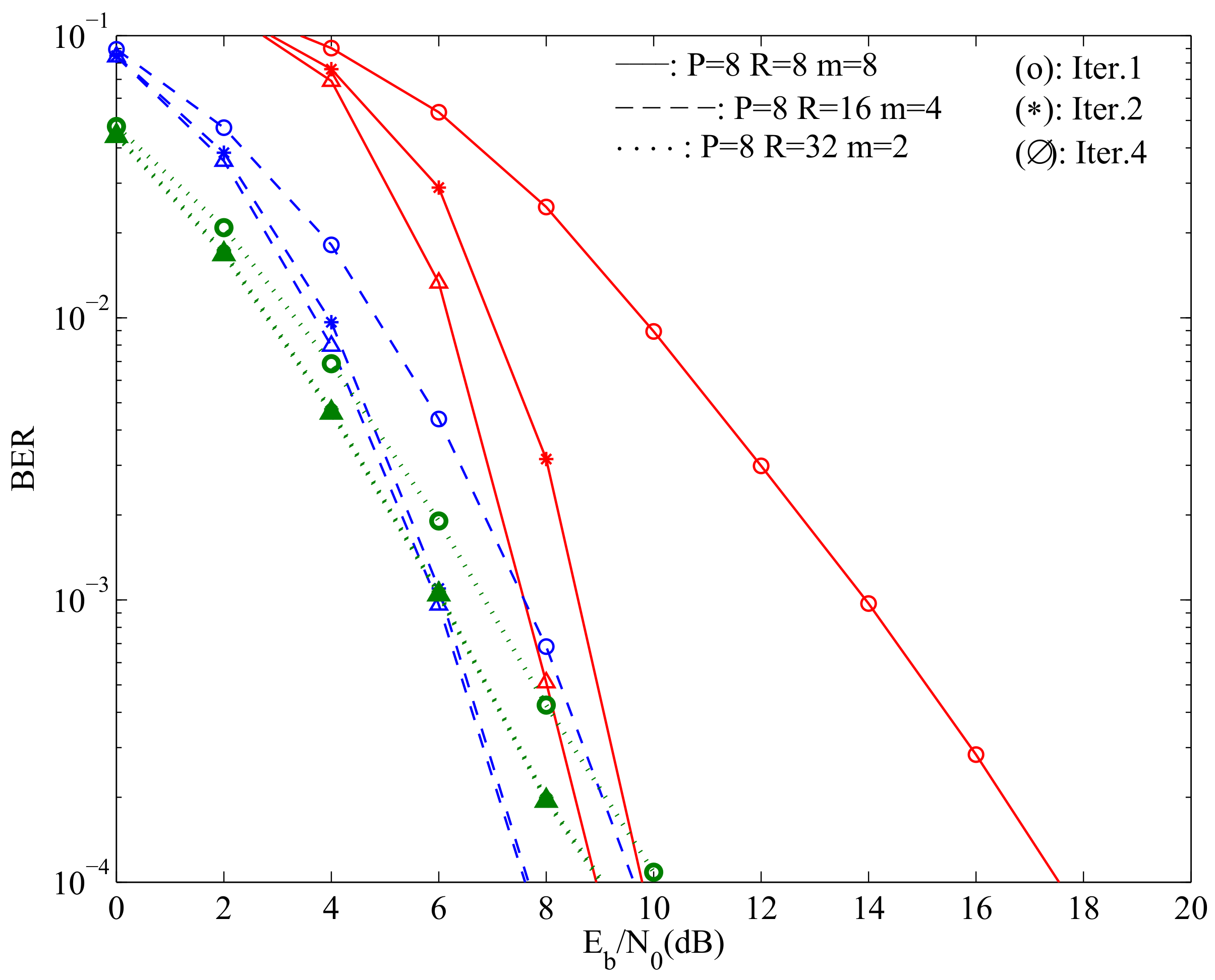
Figure 7 depicts the average BER performance from all users in a scenario with
MTs. The transmission scenarios are
with
,
with
and
with
.
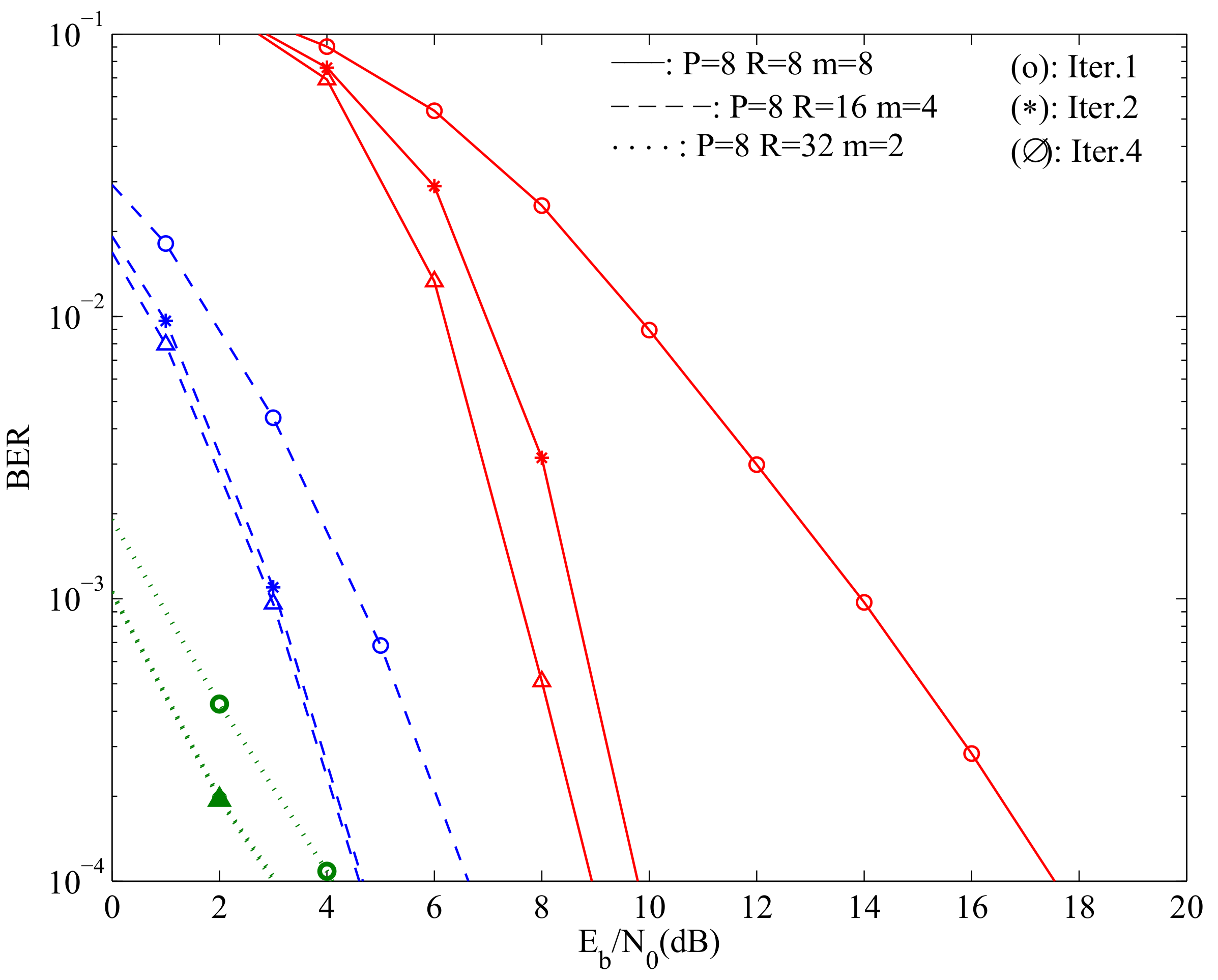
In this figure, one can notice that the degradation inherent to considering low resolution quantizers is to some degree compensated by the gains of working with higher dimension matrices, as the matrices to invert are better conditioned and with lesser residual interference. For the same scenario as
Figure 7,
Figure 8 expresses the BER as a function of the total transmit power instead of the total received power (which are identical in the
case since the channel is normalized to have
), with clear gains when
, even if we have lower resolution quantizers.

