Transmission Performance of an OFDM-Based Higher-Order Modulation Scheme in Multipath Fading Channels

1
Department of Information and Communications Engineering, Kogakuin University, Tokyo 163-8677, Japan
2
Graduate School of Engineering, Kogakuin University, Tokyo 163-8677, Japan
*
Author to whom correspondence should be addressed.
J. Sens. Actuator Netw. 2019, 8(2), 19; https://doi.org/10.3390/jsan8020019
Submission received: 26 February 2019
/
Revised: 20 March 2019
/
Accepted: 24 March 2019
/
Published: 27 March 2019
(This article belongs to the Special Issue Trends, Issues and Challenges toward 5G and beyond)
Abstract
:Fifth-generation (5G) mobile systems are a necessary step toward successfully achieving further increases in data rates. As the use of higher-order quadrature amplitude modulation (QAM) is expected to increase data rates within a limited bandwidth, we propose a method for orthogonal frequency division multiplexing (OFDM)-based 1024- and 4096-QAM transmission with soft-decision Viterbi decoding for use in 5G mobile systems. Through evaluation of the transmission performance of the proposed method over multipath fading channels using link-level simulations, we determine the bit error rate (BER) performance of OFDM-based 1024- and 4096-QAM as a function of coding rate under two multipath fading channel models: extended pedestrian A (EPA) and extended vehicular A (EVA). We also demonstrate the influence of phase error on OFDM-based 1024- and 4096-QAM and clarify the relationship between phase error and the signal-to-noise ratio (SNR) penalty required to achieve a BER of 1 × 10⁻². This work provides an effective solution for introducing higher-order modulation schemes in 5G and beyond.
1. Introduction
Fifth-generation (5G) mobile systems are being developed worldwide with the objectives of increasing system capacity and data rates, achieving low latency, improving user throughput, and supporting “Internet of Things” services. These systems are expected to deliver peak data rates of up to 20 Gbps and 100 times higher typical data rates per user (user throughput) [1,2,3,4]. Fourth-generation (4G) mobile systems such as long term evolution (LTE) and LTE-Advanced mobile systems apply quadrature phase shift keying (QPSK), 16-quadrature amplitude modulation (QAM), and 64-QAM for the symbol modulation of orthogonal frequency division multiplexing (OFDM), as defined by Release 8 of the Third Generation Partnership Project (3GPP) standards body. Although the highest modulation scheme under Release 8 was 64-QAM for LTE, 3GPP Release 12 discussed the implementation of 256-QAM, and more recently, 3GPP Release 15 introduced 1024-QAM support. Nevertheless, the application areas and/or conditions for these post-64-QAM schemes are currently very limited [5,6,7].
One of the most noteworthy technological pathways toward implementing 5G is increasing infrastructure density, which can reduce the distance between the user equipment (UE) and evolved node B (eNB), thereby improving the link budget between UE and eNB. The small-cell strategy is one of a number of denser infrastructure approaches in which a macro-cell is divided into several small-cells [8,9], which can improve both system capacity and link budget because each eNB in a small-cell is directly connected to a core network. As another small-cell strategy, the concept of a phantom cell, has been proposed to provide efficient management of radio resources and mobility operation, where small-cells are overlaid on a macro-cell [10,11]. This approach splits the control and user-data planes; that is, the macro-eNB manages all UE within the overlaid cells, although UE can connect to a neighboring low-power eNB in the small-cell.
Heterogeneous networks (HetNets) are another solution of denser infrastructures in which small- or pico-cells with low-power eNBs are installed within the coverage area of a macro-cell [12,13,14,15,16]. The objective of HetNet is to allow the UE to access pico-cells that overlap within a geographical coverage area even when the UE is within the coverage of a donor macro-cell. In other words, when the traffic in the donor macro-cell increases, its UE can access the pico-cells automatically. Through this mechanism, HetNet can increase system capacity, particularly when there is the heavy traffic in the macro-cell.
Relay systems are an alternative approach to denser infrastructures that are primarily useful in improving cell edge performance in macro-cells [17,18,19]. In this scheme, a relay node (RN) installed at a macro-cell edge where the received signal power from the serving eNB is low can transmit a strengthened signal to the UE. Thus, the RN can physically reduce the distance between eNB and UE. Three-dimensional (3D) beamforming is another key technology for achieving 5G in which antenna beams can be individually tailored to each UE in the elevation domain through the use of a massive multiple-input and multiple-output (MIMO) antenna architectures. The use of 3D beamforming by MIMO antennas enables directs signal transmission toward a target UE, potentially increasing the received signal-to-noise ratio (SNR) or signal-to-interference plus noise ratio (SINR) while reducing the interference directed to adjacent cells and other UEs [20,21,22].
New technologies such as the small-cell strategy, HetNets, relay systems, and 3D beamforming that improve the received SINR will enhance the introduction of higher-order QAM schemes. Previously, we proposed OFDM-based 256-, 1024-, and 4096-QAM for use in mobile systems and determined the fundamental transmission performance needed for the use of hard-decision Viterbi decoding in a typical additive white Gaussian noise (AWGN) channel [23,24,25,26]. However, the transmission performance of higher-order QAM with soft-decision Viterbi decoding in multipath fading channels has not been sufficiently investigated.
On the basis of this background, in this study we investigate the transmission performance of OFDM-based 1024- and 4096-QAM with soft-decision Viterbi decoding in multipath fading channels using link-level simulations. Specifically, we clarify the bit error rate (BER) performance of OFDM-based 1024- and 4096-QAM as a function of coding rate under two multipath fading channel models: extended pedestrian A (EPA) and extended vehicular A (EVA). We also demonstrate the influence of phase error on OFDM-based 1024- and 4096-QAM and clarify the relationship between phase error and the SNR penalty required to achieve a BER of 1 × 10⁻².
This paper is organized as follows. In Section 2, we introduce an OFDM-based 1024- and 4096-QAM transmission model and its associated computer simulation conditions. In Section 3, we discuss the BER performance of OFDM-based 1024- and 4096-QAM in multipath fading channels and the SNR penalty in the presence of phase error. Finally, we conclude our work in Section 4.
2. Transmission Model and Simulation Conditions
2.1. Application Example
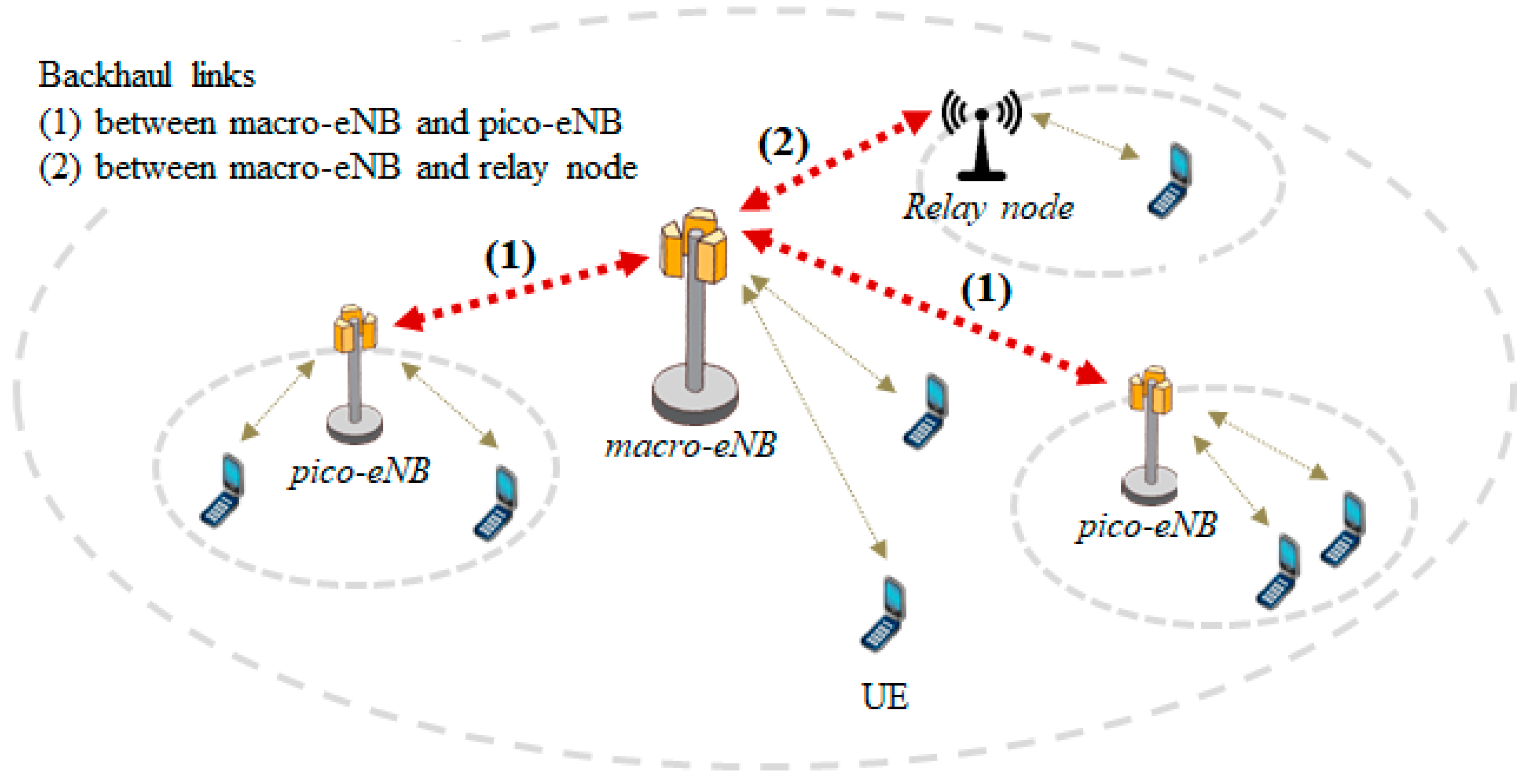
Higher-order modulation schemes require higher levels of received SINR to correctly demodulate transmission signals, because the higher-order modulation scheme is very sensitive to noise, nonlinear distortion, interference, and multipath fading. To keep higher received SINR, higher-order modulation schemes such as 1024- and 4096-QAM can be implemented in point-to-point systems, e.g., in backhaul links with line-of-sight propagation conditions. Figure 1 shows an application example of higher-order modulation schemes used in HetNet, where a large macro-cell operated by macro-eNB is combined with pico-cells operated by pico-eNB. In this case, the downlink SINR received at pico-eNB will be higher because the transmission link between the macro-eNB and pico-eNB is fixed and the antennas of pico-eNB are located higher than UE. Consequently, a higher-order modulation scheme can be implemented to the backhaul link between the macro-eNB and pico-eNB, as shown in Figure 1. Figure 1 also includes a relay system operated by a relay node, where the relay node is installed around a macro-cell edge to recover, amplify and retransmit to the UE, a now strengthened but previously poor signal received from the macro-eNB. Similarly, a higher-order modulation scheme can be implemented to the backhaul link between the macro-eNB and relay node [26,27]. It is also expected that higher-order modulation schemes will be used to directly link between eNBs and UE over limited areas, e.g., in small-cell systems with very little interference, in indoor environments, and so on. However, in the near future, higher-order modulation schemes will diffuse through the use of enhanced technologies such as powerful coding and highly precise 3D beamforming.
2.2. Transmission Model
Figure 2 shows a transmission model of an OFDM-based higher-order modulation schemes in downlink with a single antenna branch. The transmitter includes an encoder, a QAM mapper, a pilot insertion, an inverse fast Fourier transform (IFFT), and a cyclic prefix (CP) insertion. Input baseband signals are encoded via turbo coding which is typically used in 4G systems. The encoded signals are converted to QAM mapper to produce a 1024- or 4096-QAM signal. Then, the IFFT forms OFDM signals. Finally, a CP in the form of a copy of the tail of a symbol placed at its beginning is inserted to reduce inter symbol interference. Pilot insertion is used to estimate the channel response at the receiver side under multipath fading conditions. At the receiver side, first the CP is removed and the FFT then separates the individual subcarrier components and converts them to QAM format. Each component signal is then demodulated by the QAM de-mapper. Finally, the soft-decision Viterbi decoding is used to output the original baseband signals. Channel estimation and channel equalization are used to compensate received signals distorted by multipath fading.
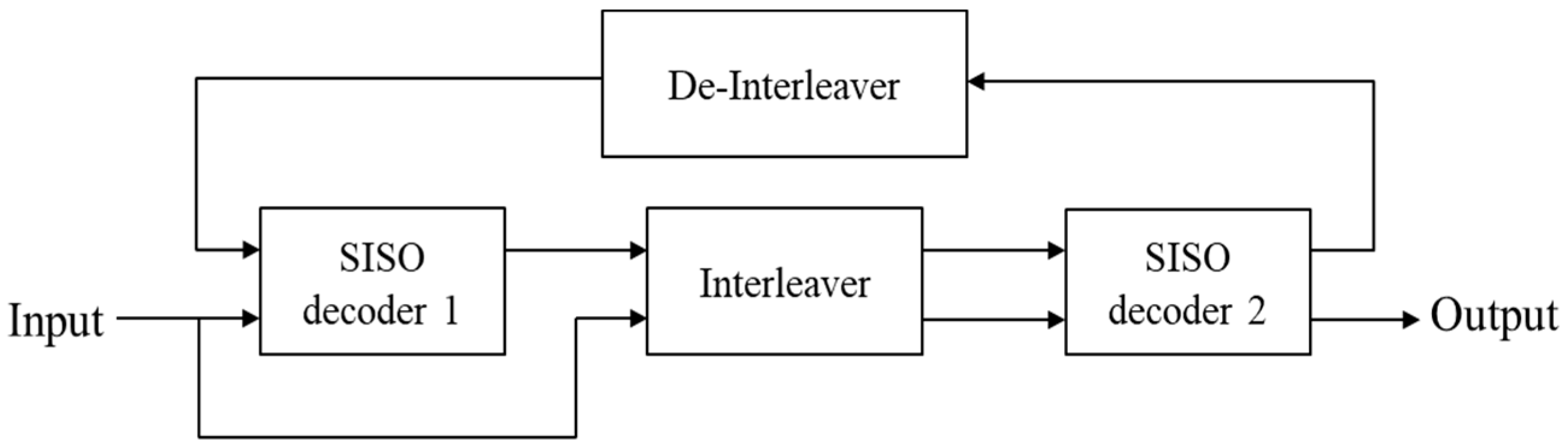
Figure 3 shows a block diagram of the turbo encoder (coding rate = 1/3), which uses two identical convolutional encoders (1st and 2nd encoders) with a constraint length of four and one internal interleaver. Figure 4 shows a block diagram of the soft-decision Viterbi decoder, which comprises two single soft-in soft-out (SISO) decoders that work iteratively, with the output of the first decoder (SISO decoder 1) feeding into the second decoder (SISO decoder 2) to form a turbo decoding iteration. During this process, interleaver and de-interleaver blocks re-order the data [28,29].
The computer simulation parameters are listed in Table 1. The IFFT/FFT size is 2048 which corresponds to a transmission bandwidth of 20 MHz, and the subcarrier spacing of OFDM is 15 kHz. The coding rates of the turbo encoder are assumed to be 1/3, 1/2, 2/3, 3/4, and 1, and the constraint length is fixed at four. QAM signals are mapped by the rule of Gray-code. The CP is produced using 1024 samples for seven OFDM symbols, the first of which uses 160 samples as the CP, with the remaining six using 144 samples. This is referred to as normal CP in LTE mobile systems.
The multipath fading channels specify the following two profiles, extended pedestrian A (EPA) and extended vehicular A (EVA), whose delay profiles represent low and medium delay spreads, respectively, as listed in Table 2 [30]. Doppler frequency shift is an apparent change in the carrier frequency due to the relative motion of two objects (here, the eNB and UE). The maximum Doppler frequency shift is fixed at 5 Hz, assuming a UE velocity of 3 km/h for the carrier frequency band of 2 GHz.
3. Simulation Results
3.1. Fundamental Bit Error Rate (BER) Performance under Additive White Gaussian Noise (AWGN)
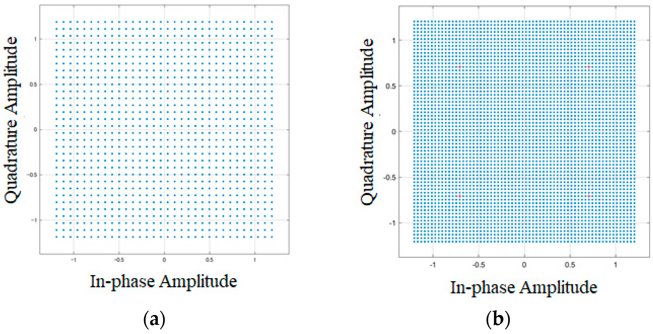
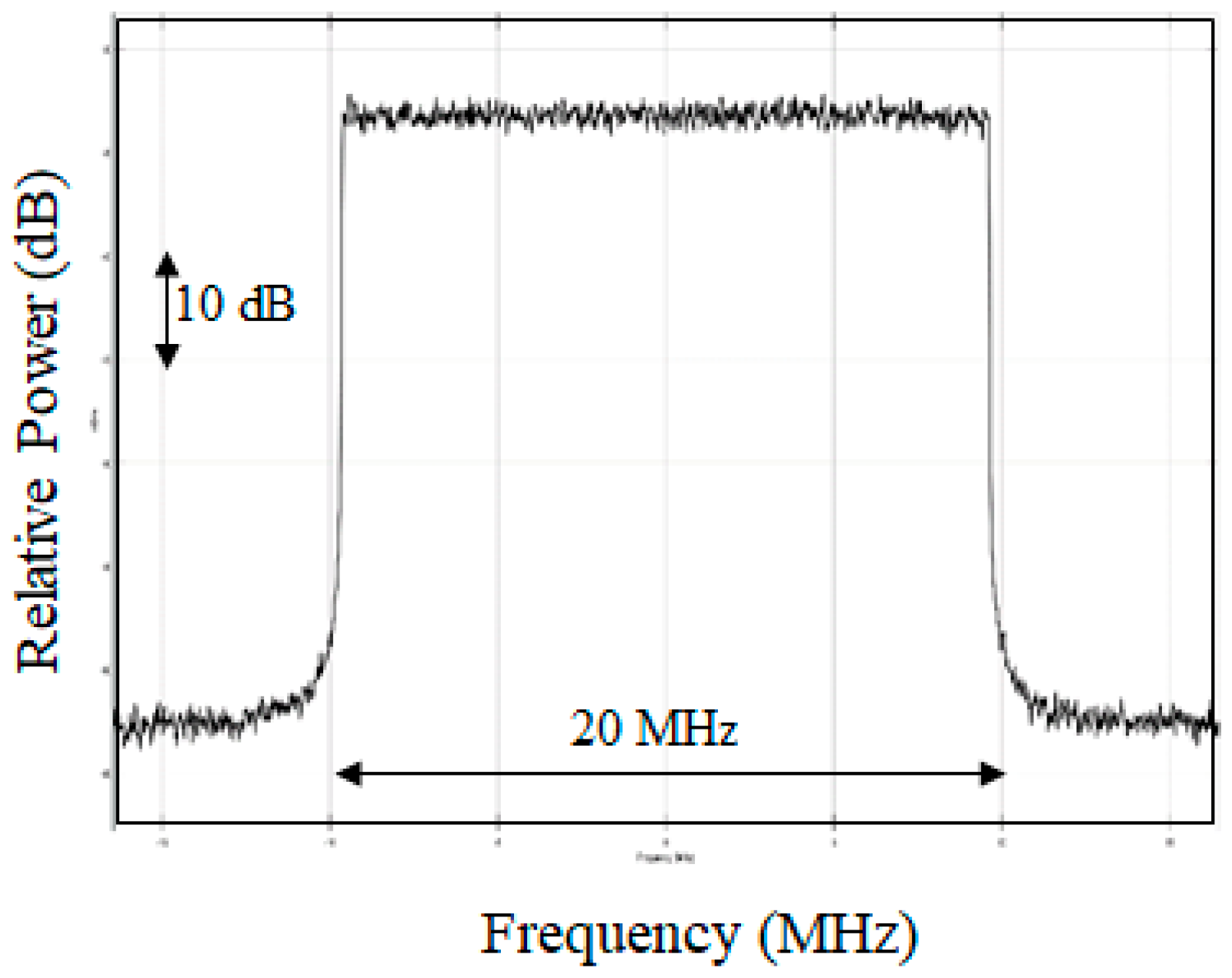
Figure 5a,b shows the signal constellation for 1024- and 4096-QAM, respectively, at the transmitter side. As the multilevel (order) of QAM increases, the Euclidean distance among signal constellations naturally shortens, as shown in Figure 5. Figure 6 shows the observed instantaneous OFDM spectrum for 1200 subcarriers containing 1024- or 4096-QAM symbol modulation signals.
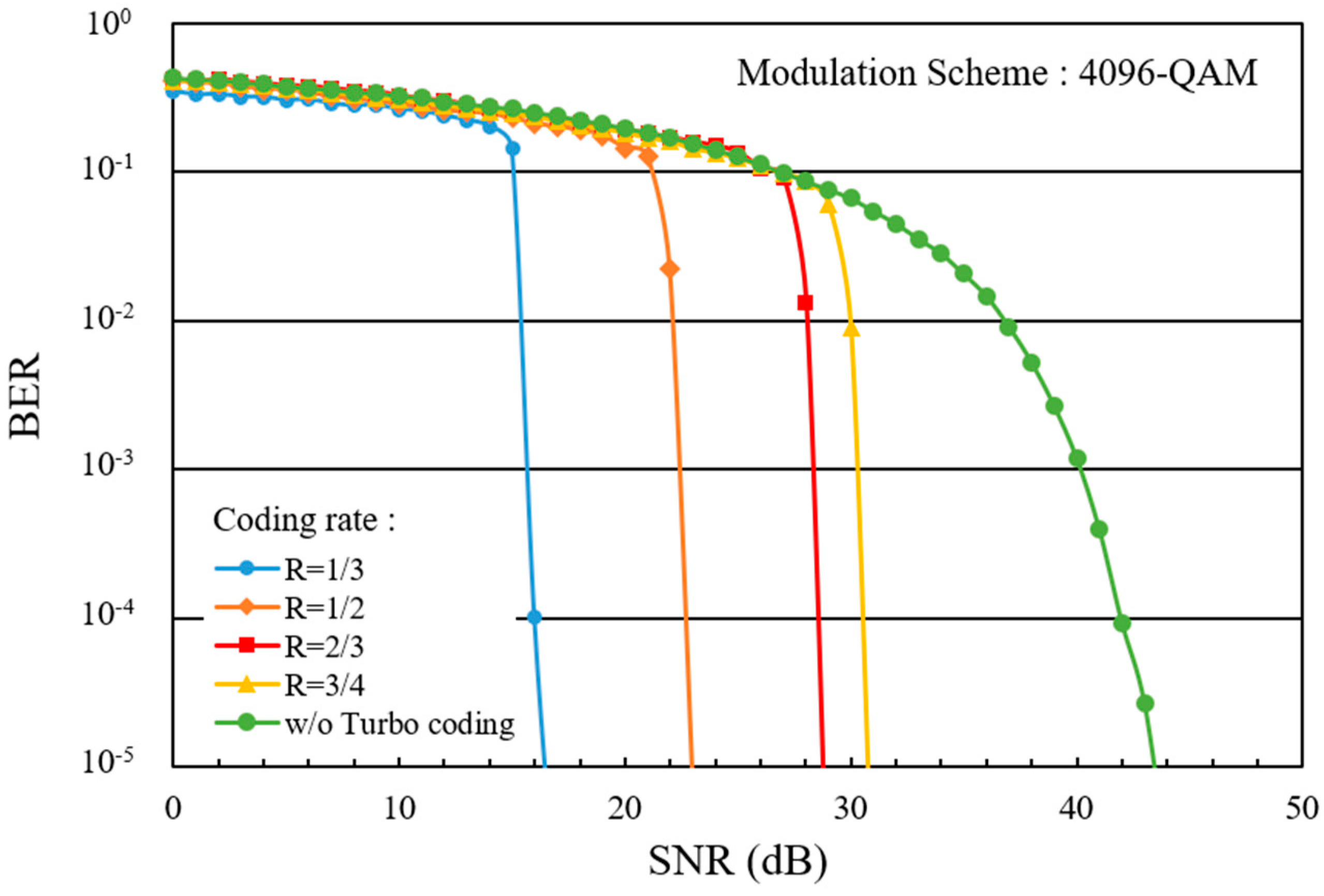
Figure 7 plots the fundamental BER against received SNR of 1024-QAM at various coding rates, R, under an AWGN channel condition. The BER is measured by comparing the demodulated serial bits with the original binary serial bits. In this work, we assume a benchmark BER of 1 × 10⁻². When turbo coding and soft-decision Viterbi decoding are used, the SNRs needed to achieve a BER of 1 × 10⁻² at coding rates R of 1/3, 1/2, 2/3, and 3/4, which are approximately 14 dB, 19 dB, 23 dB, and 25 dB, respectively. The BER at a coding rate of one, i.e., without coding (w/o), is also plotted as a reference. Figure 8 plots the fundamental BER against received SNR of 4096-QAM at various coding rates under the condition of AWGN channels. The SNRs needed to achieve a BER of 1 × 10⁻² at coding rates of 1/3, 1/2, 2/3, and 3/4 are approximately 16 dB, 22 dB, 28 dB, and 30 dB, respectively. Relative to 1024-QAM, the SNRs needed to achieve the benchmark BER of 1 × 10⁻² for 4096-QAM are increased by approximately 2 dB, 3 dB, 5 dB, and 5 dB at coding rates of 1/3, 1/2, 2/3, and 3/4, respectively. Figure 9 shows an overall comparison of BERs for QPSK, 16-, 64-, 256-, 1024-, and 4096-QAM at coding rates of 1/3 (blue lines) and 3/4 (red lines). The SNRs required for 4096-QAM at these coding rates are, respectively, 17 dB and 26 dB higher than those required for QPSK. Current LTE mobile systems use a link adaptation technology that can choose a modulation scheme and coding rates depending on the channel quality, i.e., received SNR or SINR. The results in Figure 9 suggest that if 4096-QAM is used for the “modulation and coding sets (MCS)”, 4096-QAM at coding rates of 1/3 or 3/4 can be assigned to a UE at received SINRs of more than 16 dB or 30 dB, respectively. Similarly, 1024-QAM at a coding rate of 1/3 can be assigned to a UE at received SINR of more than 14 dB.
3.2. SNR Penalty in the Presence of Phase Error
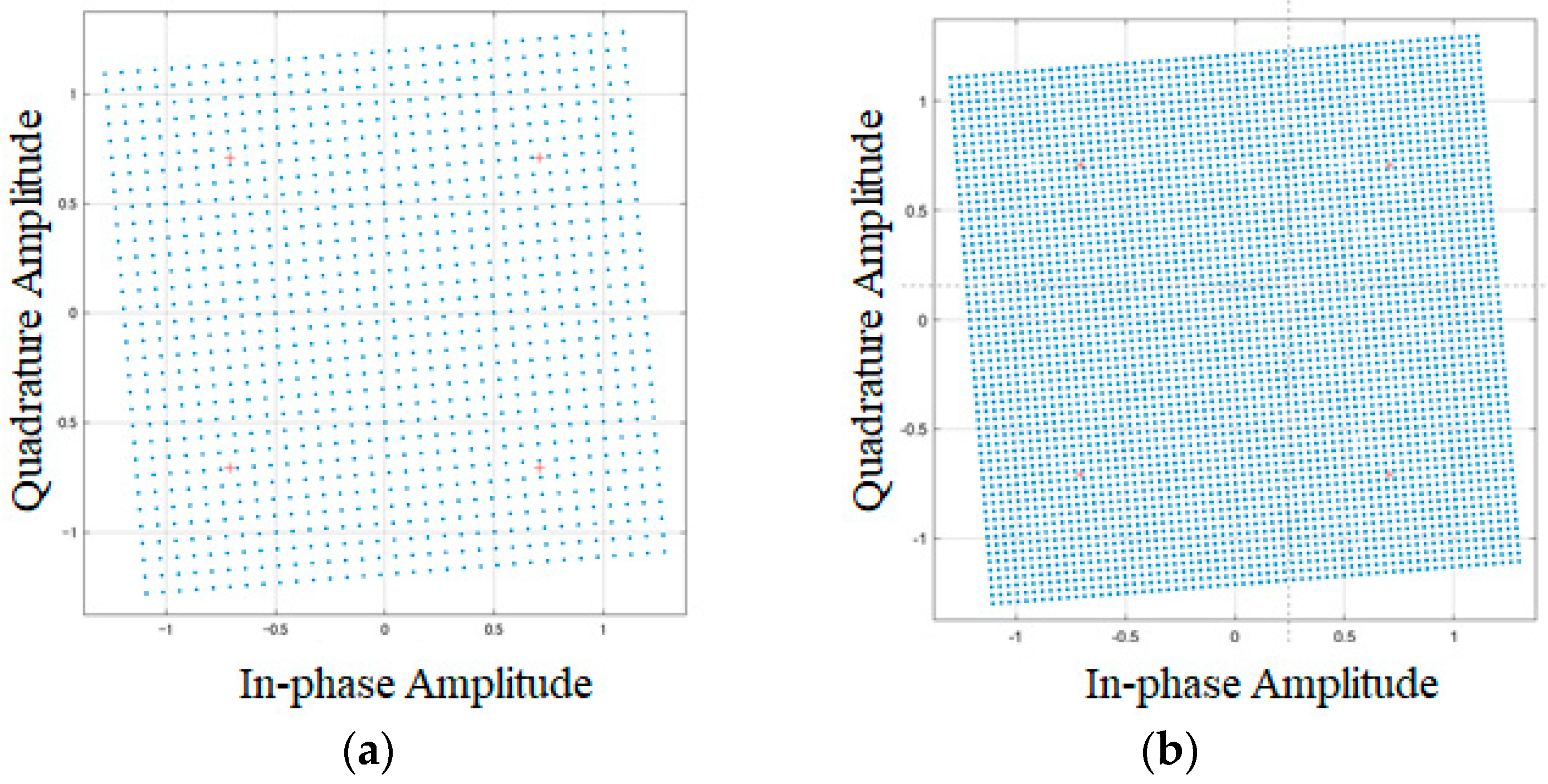
We then evaluate the influence of phase error which is measured in units of radians. Figure 10a,b shows photos of signal constellations for 1024- and 4096-QAM, respectively, at a phase error of 0.08. In general, the BER worsens as the phase error increases, because higher-order QAM has a weakness for errors in amplitude and phase as a result of the shortening Euclidean distance. In some cases, the QAM can no longer meet a BER of 1 × 10⁻² even if SNR is increased.
Figure 11 shows the BER of 1024-QAM as a function of phase error at a coding rate of 1/3. At phase errors of 0.10 and 0.15, the SNRs needed to achieve a BER of 1 × 10⁻² are increased by approximately 1.5 dB and 5 dB, respectively, relative to the no-phase-error case. When the phase error is increased to 0.20, 1024-QAM can no longer achieve a BER of 1 × 10⁻² even if the SNR is increased.
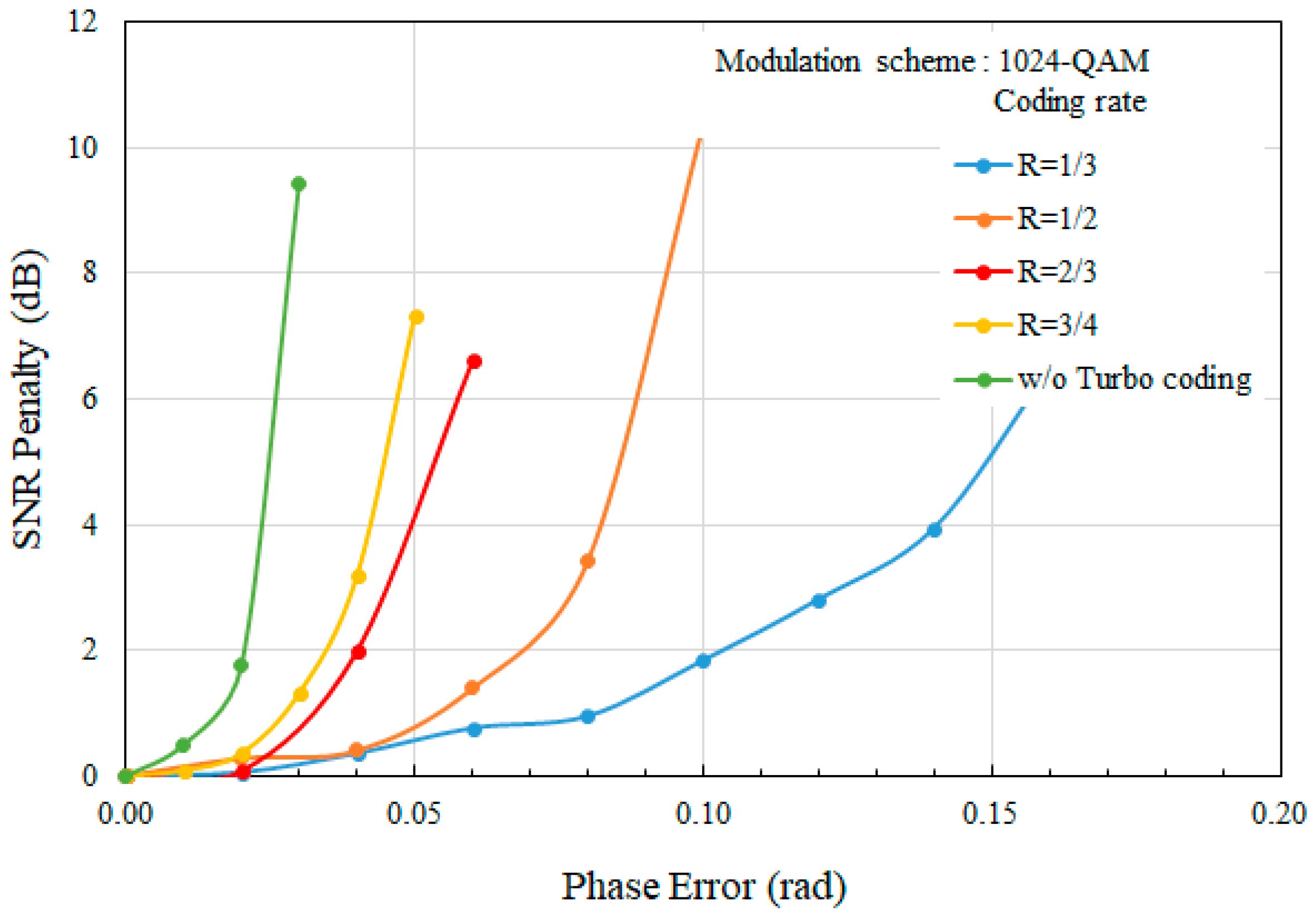
Figure 12 shows the SNR penalty needed to achieve a BER of 1 × 10⁻² against phase error for 1024-QAM at various coding rates. It is clearly observed that the SNR penalty increases as the phase error increases. The SNR penalty is approximately 6 dB at a phase error of 0.05 and a coding rate of 3/4. To reduce the SNR penalty to below 3 dB, the phase error cannot exceed 0.04 at coding rates of 3/4 or below.
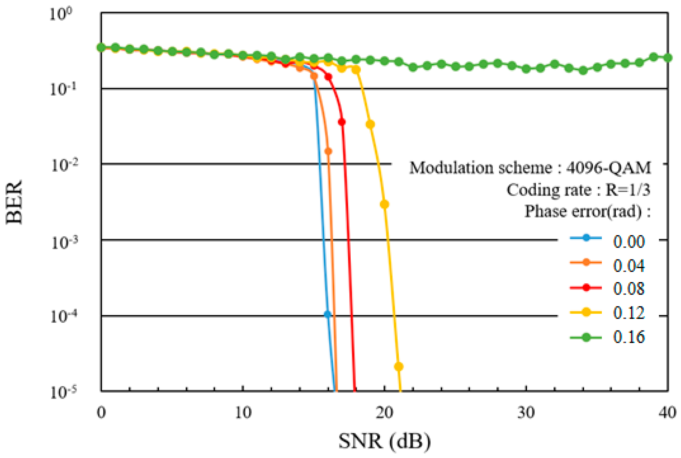
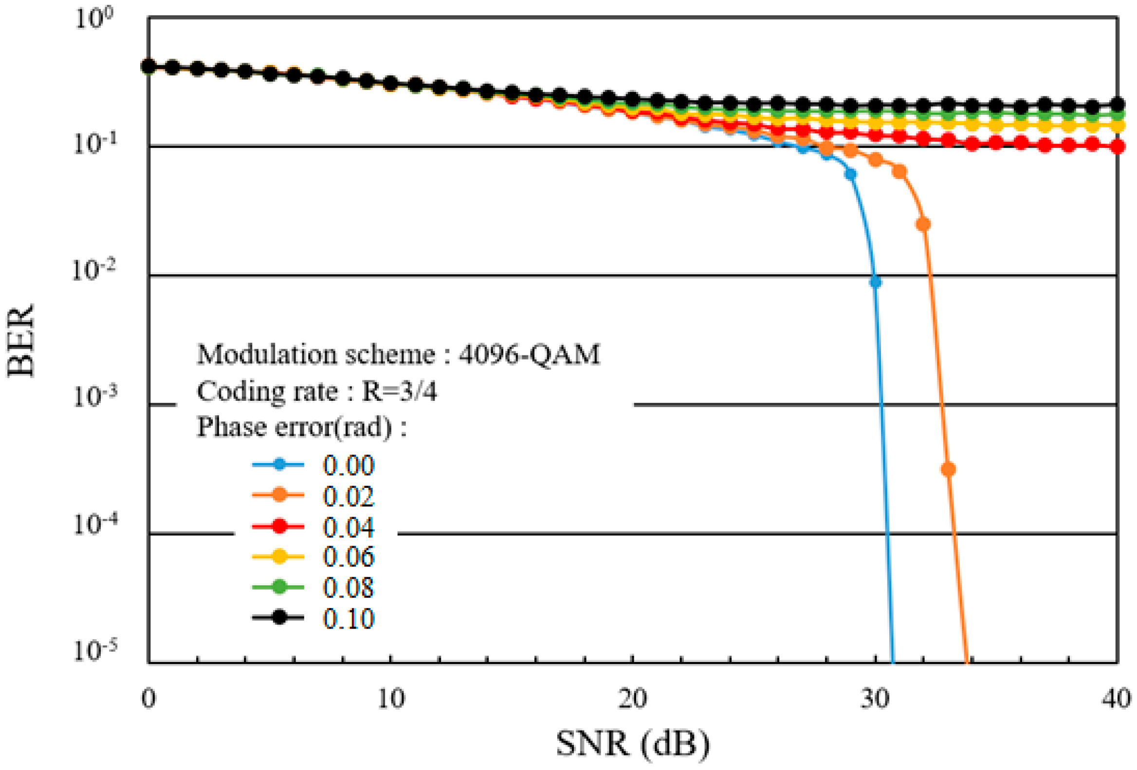
Figure 13 shows the BER of 4096-QAM as a function of phase error at a coding rate of 1/3. At phase errors of 0.08 and 0.12, the SNRs needed to achieve a BER of 1 × 10⁻² are increased by approximately 2 dB and 4 dB, respectively, relative to the no-phase-error case. When the phase error is increased 0.16, 4096-QAM can no longer achieve a BER of 1 × 10⁻², even if the SNR is increased. Figure 14 shows the BER of 4096-QAM as a function of phase error at a coding rate of 3/4. Relative to the case for which the coding rate of 1/3, the BER is worse, and when the phase error is increased to 0.04, 4096-QAM can no longer achieve a BER of 1 × 10⁻² even if the SNR is increased.
Figure 15 plots the SNR penalty needed to achieve a BER of 1 × 10⁻² against phase error for 4096-QAM at various coding rates. At a phase error of 0.03 and a coding rate of 2/3, the SNR penalty of 4096-QAM is approximately 6 dB. To reduce the SNR penalty to less than 3 dB, the phase error must be no greater than 0.024 at a coding rate of 3/4 or below.
Figure 16 plots the SNR penalty required to achieve a BER of 1 × 10⁻² against phase error for QPSK, 16-, 64-, 256-, 1024-, and 4096-QAM at a coding rate of 1/3. Phase error severely impacts 1024- and 4096-QAM compared with existing QAM and QPSK schemes. To limit the SNR penalty to below 3 dB, the phase errors for 16-, 64-, 256-, 1024-, and 4096-QAM must be no greater than 0.39, 0.31, 0.18, 0.12, and 0.11, respectively.
3.3. BER Performance in Multipath Fading Channels
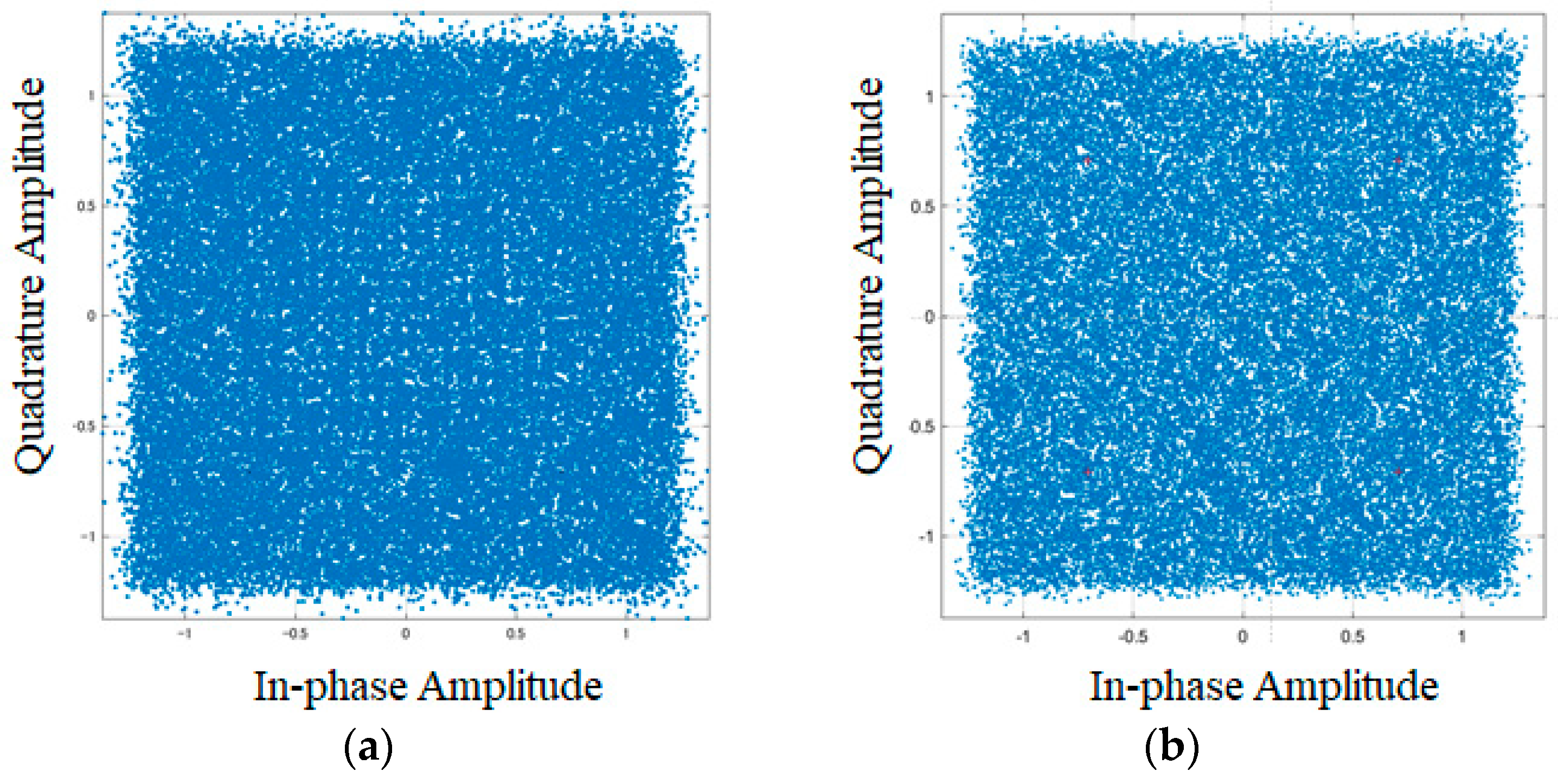
Next, we evaluate the BER performance of 1024- and 4096-QAM in the multipath fading channels listed in Table 2. Figure 17a,b show the signal constellations for 1024- and 4096-QAM, respectively, observed at a receiver side affected by EPA fading. Figure 18 shows the instantaneous OFDM spectrum observed at the receiver side. Channel estimation and channel equalization, as shown in Figure 2, play an important role to compensate these distorted signals at the receiver side. If the channel estimation and channel equalization do not work sufficiently, the BER performance worsens.
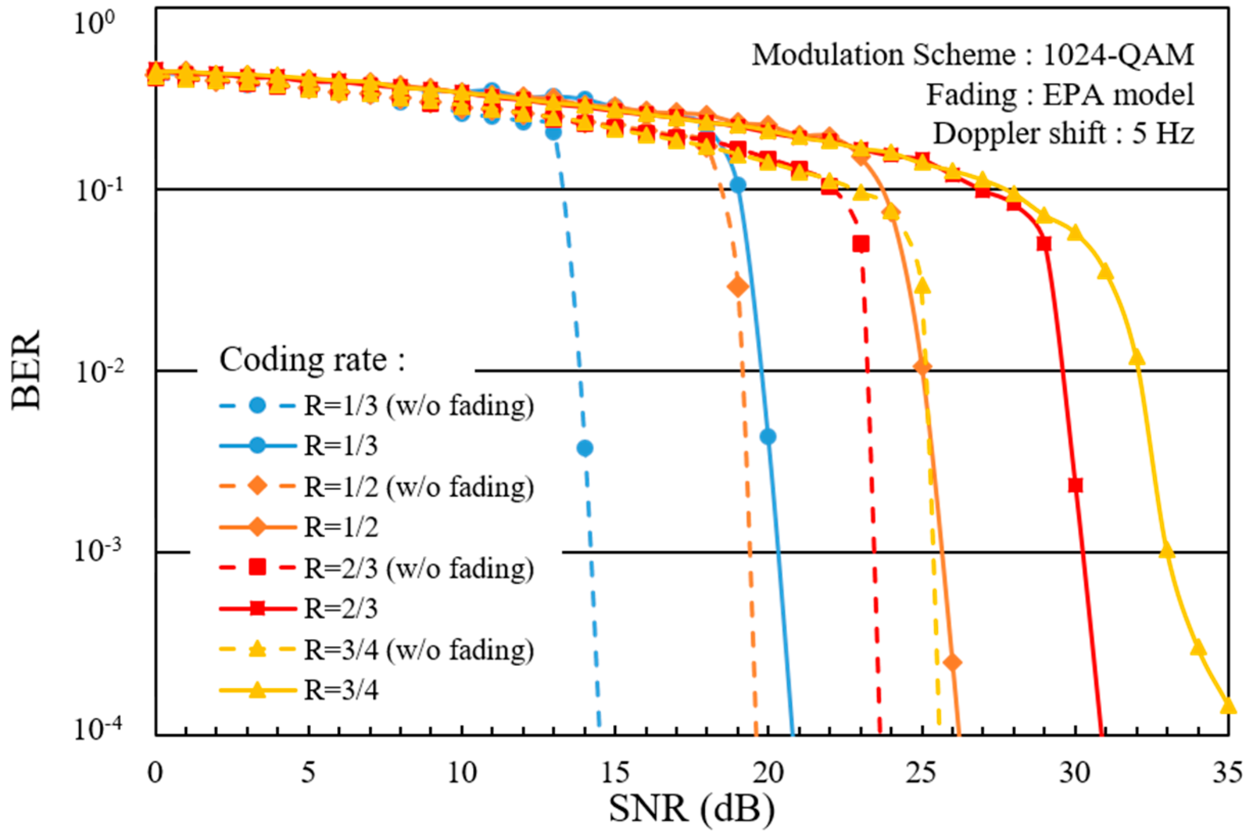
Figure 19 plots the BER of 1024-QAM against received SNR under EPA fading at coding rates of 1/3, 1/2, 2/3, and 3/4. The broken line indicates the BER obtained without fading (w/o fading), i.e., under static conditions. At a coding rate of 1/3, the SNR needed to achieve a BER of 1 × 10⁻² is approximately 20 dB, which is approximately 6 dB higher than what is required under the static condition. This behavior is similar to that observed at the other coding rates. The performance degradation is assumed to be affected by Doppler frequency shift and by imperfections in the channel estimation process.
Figure 20 plots the BER of 1024-QAM against received SNR under the EVA fading model. Compared to the EPA fading case, the BER performance is significantly degraded. At a coding rate of 1/3, the SNR required to achieve a BER of 1 × 10⁻² is approximately 22 dB, which is approximately 8 dB higher than that is required under the static condition. At coding rates above 2/3, 1024-QAM can no longer achieve a BER of 1 × 10⁻².
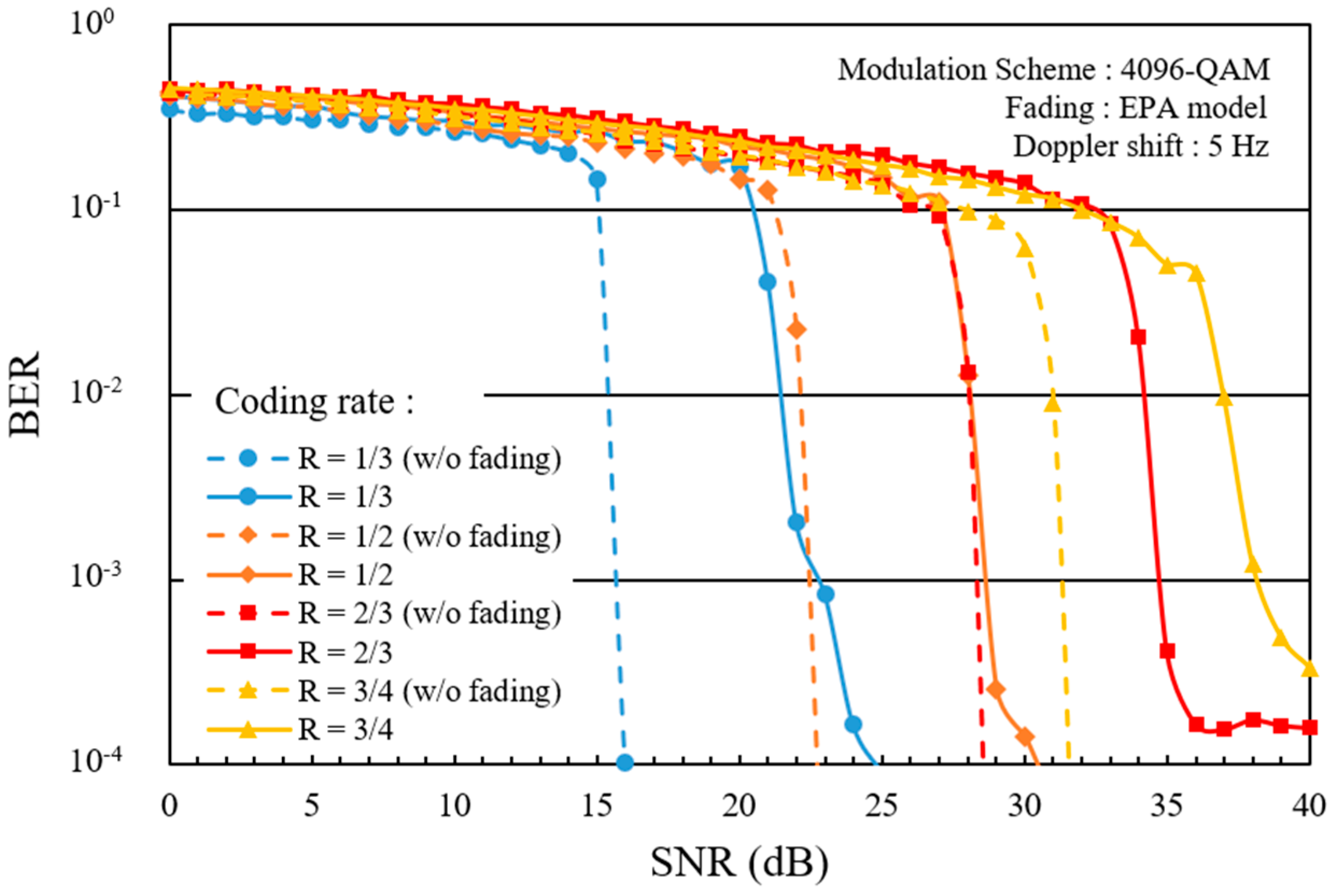
Figure 21 plots the BER of 4096-QAM against received SNR under EPA fading at coding rates of 1/3, 1/2, 2/3, and 3/4. At a coding rate of 1/3, the SNR required to achieve a BER of 1 × 10⁻² is approximately 22 dB, which is approximately 7 dB higher than that is required under the static condition. This behavior is similar to that observed at the other coding rates. Relative to 1024-QAM, the SNRs required to achieve a BER of 1 × 10⁻² at coding rates of 1/3, 1/2, 2/3, and 3/4 under EPA fading are increased by approximately 2–5 dB.
Figure 22 plots the BER of 4096-QAM against received SNR under EVA fading. At a coding rate of 1/3, the SNR required to achieve a BER of 1 × 10⁻² is approximately 24 dB, which is approximately 9 dB higher than that is required under the static condition. At coding rates greater than 1/2, 4096-QAM can no longer achieve a BER of 1 × 10⁻².
4. Conclusions
In this paper, we proposed OFDM-based 1024-and 4096-QAM schemes that apply soft-decision Viterbi decoding for use in the 5G environment and beyond. Using link-level simulations, we presented the transmission performance of the proposed scheme under two multipath fading channel models, extended pedestrian A (EPA) and extended vehicular A (EVA), as functions of coding rate. Under EPA fading, the SNRs required to achieve a BER of 1 × 10⁻² were determined to be approximately 20 dB and 22 dB at a coding rate of 1/3 for 1024- and 4096-QAM, respectively, which are approximately 6 dB and 7 dB higher than what is required under the static condition. Similarly, under EVA fading, the SNRs required to achieve a BER of 1 × 10⁻² is approximately 22 dB and 24 dB at a coding rate of 1/3 for 1024- and 4096-QAM, respectively, which are approximately 8 dB and 9 dB higher than what is required under the static condition. We also found that, under EVA fading, 1024- and 4096-QAM can no longer achieve a BER of 1 × 10⁻² at coding rates greater than 2/3 and 1/2, respectively. We determined the relationship between phase error and the SNR penalty required to achieve a BER of 1 × 10⁻² for the proposed scheme as well as for the existing QAM and QPSK scheme. We found that 1024-QAM can no longer achieve a BER of 1 × 10⁻², at phase errors of 0.20 or above even if the SNR is increased. Similarly, 4096-QAM can no longer achieve a BER of 1 × 10⁻² at phase errors of 0.16 or above. To limit the SNR penalty to below 3 dB, the phase errors for 16-, 64-, 256-, 1024-, and 4096-QAM cannot be higher than 0.39, 0.31, 0.18, 0.12, and 0.11, respectively. In our future work, we will use system-level computer simulation to clarify the user throughput performance of mobile systems in which 1024- and 4096-QAM are incorporated into the modulation and coding sets (MCS).
Author Contributions
Conceptualization, H.O. and R.T.; Investigation, H.O. and R.T. and K.S.; Data curation, R.T. and K.S.; Writing—original draft preparation, H.O.; Writing—review and editing, H.O.; Visualization, R.T. and K.S.; Supervision, H.O.; Project administration, H.O.; Funding acquisition, H.O.
Funding
This research was funded by JSPS KAKENHI Grant Number JP18K11277, Grant-in-Aid for Scientific Research (C).
Acknowledgments
The authors would like to thank T. Ota and M. Nakamura who are graduates of Kogakuin University for their contributions to construct link-level simulations.
Conflicts of Interest
The authors declare no conflict of interest.
References
- 3GPP News. 3GPP system standards heading into the 5G era. 3GPP, 2014. Available online: http://www.3gpp.org/news-events/3gpp-news/1614-sa_5g (accessed on 18 March 2019).
- Draft new recommendation ITU-R M. IMT for 2020 and beyond. ITU-R, September 2015. Available online: https://www.itu.int/dms_pubrec/itu-r/rec/m/R-REC-M.2083-0-201509-I!!PDF-E.pdf (accessed on 18 March 2019).
- Soldani, D.; Manzalini, A. Horizon 2020 and beyond: On the 5G operating system for a truly digital society. IEEE Veh. Tech. Mag. 2015, 10, 32–42. [Google Scholar] [CrossRef]
- Nakamura, T.; Benjebbour, A.; Kishiyama, Y.; Suyama, S.; Imai, T. 5G radio access: Requirements, concept and experimental trials. IEICE Trans. Commun. 2015, E98B, 1397–1406. [Google Scholar] [CrossRef]
- Mu, Q.; Liu, L.; Chen, L.; Jiang, Y. CQI table design to support 256 QAM in small cell environment. In Proceedings of the 2013 International Conference on Wireless Communications and Signal Processing, Hangzhou, China, 24–26 October 2013; pp. 1–5. [Google Scholar] [CrossRef]
- Mao, J.; Abdullahi, M.A.; Xiao, P.; Cao, A. A low complexity 256QAM soft demapper for 5G mobile system. In Proceedings of the 2016 European Conference on Networks and Communications (EuCNC), Athens, Greece, 27–30 June 2016; pp. 1–6. [Google Scholar] [CrossRef]
- 3GPP TR 36.783. Evolved Universal Terrestrial Radio Access (E-UTRA); Introduction of 1024 Quadrature Amplitude Modulation (QAM) in LTE downlink (Release 15). 3GPP, April 2017. Available online: https://portal.3gpp.org/desktopmodules/Specifications/SpecificationDetails.aspx?specificationId=3207 (accessed on 18 March 2019).
- Dahlman, E.; Dimou, K.; Parkvall, S.; Tullberg, H. Future wireless access small cells and heterogeneous deployments. In Proceedings of the ICT 2013, Casablanca, Morocco, 6–8 May 2013. [Google Scholar] [CrossRef]
- Elsherif, A.R.; Chen, W.P.; Ito, A.; Ding, Z. Resource allocation and inter-cell interference management for dual-access small cells. IEEE J. Sel. Areas Commun. 2015, 33, 1082–1096. [Google Scholar] [CrossRef]
- Ishii, H.; Kishiyama, Y.; Takahashi, H. A novel architecture for LTE-B: C-plane/U-plane split and phantom cell concept. In Proceedings of the 2012 IEEE Globecom Workshops, Anaheim, CA, USA, 3–7 December 2012; pp. 624–630. [Google Scholar] [CrossRef]
- Maria, A.D.; Panno, D. A radio resource management scheme in future ultra-dense phantom networks. In Proceedings of the 2017 IEEE 13th International Conference on Wireless and Mobile Computing, Networking and Communications (WiMob), Rome, Italy, 9–11 October 2017; Volume 1, pp. 1–6. [Google Scholar] [CrossRef]
- Ghosh, A.; Ratasuk, R.; Mondai, B.; Mangalvedhe, N.; Thomas, T. LTE-advanced: next-generation wireless broadband technology. IEEE Wireless Commun. 2010, 17, 10–22. [Google Scholar] [CrossRef]
- Khandekar, A.; Bhushan, N.; Tingfang, J.; Vanghi, V. LTE Advanced: Heterogeneous Networks. In Proceedings of the 2010 European Wireless Conference (EW), Lucca, Italy, 12–15 April 2010; pp. 978–982. [Google Scholar] [CrossRef]
- Deb, S.; Monogioudis, P.; Miernik, J.; Seymour, J.P. Algorithms for Enhanced Inter-Cell Interference Coordination (eICIC) in LTE HetNets. IEEE/ACM Trans. Netw. 2014, 22, 137–150. [Google Scholar] [CrossRef]
- Kikuchi, K.; Otsuka, H. Proposal of Adaptive Control CRE in Heterogeneous Networks. In Proceedings of the 2012 IEEE 23rd International Symposium on Personal, Indoor and Mobile Radio Communications–(PIMRC), Sydney, Australia, 9–12 September 2012. [Google Scholar] [CrossRef]
- Nakazawa, S.; Naganuma, N.; Otsuka, H. Enhanced adaptive control CRE in heterogeneous networks. In Proceedings of the 2017 14th IEEE Annual Consumer Communications & Networking Conference (CCNC), Las Vegas, NV, USA, 8–11 January 2017; pp. 645–646. [Google Scholar] [CrossRef]
- 3GPP TR 36.806. Relay architectures for E-UTRA (LTE-Advanced). 3GPP, March 2010. Available online: http://www.qtc.jp/3GPP/Specs/36806-900.pdf (accessed on 18 March 2019).
- Saleh, A.B.; Redana, S.; Raaf, B.; Riihonen, T.; Hamalainen, J.; Wiehman, R. Performance of amplify-and-forward and decode-and-forward relays in LTE-Advanced. In Proceedings of the 2009 IEEE 70th Vehicular Technology Conference Fall, Anchorage, AK, USA, 20–23 September 2009. [Google Scholar] [CrossRef]
- Bulakci, O.; Redana, S.; Raaf, B.; Hamalainen, J. Performance enhancement in LTE-Advanced relay networks via relay site planning. In Proceedings of the 2010 IEEE 71st Vehicular Technology Conference, Taipei, Taiwan, 16–19 May 2010. [Google Scholar] [CrossRef]
- Song, Y.; Yun, X.; Nagata, S.; Chen, L. Investigation on elevation beamforming for future LTE-Advanced. In Proceedings of the 2013 IEEE International Conference on Communications Workshops (ICC), Budapest, Hungary, 9–13 June 2013. [Google Scholar] [CrossRef]
- Hu, Z.; Liu, R.; Kang, S.; Su, X.; Xu, J. 3D beamforming methods with user-specific elevation beamforming. In Proceedings of the 9th International Conference on Communications and Networking in China, Maoming, China, 14–16 August 2014; pp. 383–386. [Google Scholar] [CrossRef]
- Koppenborg, J.; Halbauer, H.; Saur, S.; Hoek, C. 3D beamforming trials with an active antenna. In Proceedings of the 2012 International ITG Workshop on Smart Antennas (WSA), Dresden, Germany, 7–8 March 2012; pp. 110–114. [Google Scholar] [CrossRef]
- Iwamoto, M.; Matsuoka, S.; Iwasaki, H.; Otsuka, H. Transmission Performance of OFDM with 1024-QAM in the Presence of EVM Degradation. In Proceedings of the IEEE Asia Pacific Conference on Wireless and Mobile, Bali, Indonesia, 28–30 August 2014; pp. 12–16. [Google Scholar] [CrossRef]
- Ota, T.; Nakamura, M.; Otsuka, H. Performance Evaluation of OFDM-based 256- and 1024-QAM in Multipath Fading Propagation Conditions. In Proceedings of the 2017 Ninth International Conference on Ubiquitous and Future Networks (ICUFN), Milan, Italy, 4–7 July 2017; pp. 554–556. [Google Scholar] [CrossRef]
- Tian, R.; Senda, K.; Ota, T.; Otsuka, H. Transmission performance of OFDM-based 1024-QAM in multipath fading conditions. IEICE Commun. Express 2018, 7, 272–277. [Google Scholar] [CrossRef]
- Tian, R.; Ota, T.; Otsuka, H. Influence of phase error on OFDM-based 4096-QAM with turbo coding. In Proceedings of the 2018 International Conference on Information Networking (ICOIN), Chiang Mai, Thailand, 10–12 January 2018; pp. 352–355. [Google Scholar] [CrossRef]
- Otsuka, H.; Tanoi, N.; Ogura, N.; Kubo, T.; Asai, T.; Okumura, Y. Performance analysis of fiber-optic inband relaying in the presence of self-interferences. In Proceedings of the 2014 IEEE 80th Vehicular Technology Conference (VTC2014-Fall), Vancouver, BC, Canada, 14–17 September 2014. [Google Scholar] [CrossRef]
- Mathworks Documentations. Turbo Encoder. Available online: https://jp.mathworks.com/help/comm/ref/turboencoder.html?lang=en (accessed on 18 March 2019).
- 3GPP TS 36.212. Technical Specification Group Radio Access Network; Evolved Universal Terrestrial Radio Access (E-UTRA); Multiplexing and channel coding (Release 13). 3GPP, June 2016. Available online: https://www.arib.or.jp/english/html/overview/doc/STD-T104v4_10/5_Appendix/Rel13/36/36212-d20.pdf (accessed on 18 March 2019).
- 3GPP TS 36.104. Evolved Universal Terrestrial Radio Access (E-UTRA); Base Station (BS) radio transmission and reception (Release 8). 3GPP, May 2008. Available online: http://www.qtc.jp/3GPP/Specs/36104-820.pdf (accessed on 18 March 2019).
Figure 1.
Application example of higher-order modulation schemes such as 1024- and 4096-quadrature amplitude modulation (QAM) in backhaul links for pico-evolved node B (eNB) and a relay node. UE = user equipment.
Figure 1.
Application example of higher-order modulation schemes such as 1024- and 4096-quadrature amplitude modulation (QAM) in backhaul links for pico-evolved node B (eNB) and a relay node. UE = user equipment.

Figure 2.
Transmission model of orthogonal frequency division multiplexing (OFDM)-based 1024- and 4096-QAM. IFFT = inverse fast Fourier transform; FFT = fast Fourier transform; AWGN = additive white Gaussian noise.
Figure 2.
Transmission model of orthogonal frequency division multiplexing (OFDM)-based 1024- and 4096-QAM. IFFT = inverse fast Fourier transform; FFT = fast Fourier transform; AWGN = additive white Gaussian noise.

Figure 3.
Block diagram of turbo encoder. xk is the first systematic bit (original input bit). zk and zk’ are the outputs of 1st and 2nd encoders, respectively.
Figure 3.
Block diagram of turbo encoder. xk is the first systematic bit (original input bit). zk and zk’ are the outputs of 1st and 2nd encoders, respectively.

Figure 4.
Block diagram of soft-decision Viterbi decoder. SISO = soft-in soft-out.

Figure 5.
Signal constellation at transmitter side for (a) 1024-QAM and (b) 4096-QAM [26].
Figure 5.
Signal constellation at transmitter side for (a) 1024-QAM and (b) 4096-QAM [26].

Figure 6.
OFDM spectrum at transmitter side.

Figure 7.
Fundamental bit error rate (BER) performance of 1024-QAM as a function of coding rate. SNR = signal-to-noise ratio.
Figure 7.
Fundamental bit error rate (BER) performance of 1024-QAM as a function of coding rate. SNR = signal-to-noise ratio.

Figure 8.
Fundamental BER performance of 4096-QAM as a function of coding rate [26].
Figure 8.
Fundamental BER performance of 4096-QAM as a function of coding rate [26].

Figure 9.
BER performance for QPSK to 4096-QAM at coding rates of 1/3 and 3/4. QPSK = quadrature phase shift keying.
Figure 9.
BER performance for QPSK to 4096-QAM at coding rates of 1/3 and 3/4. QPSK = quadrature phase shift keying.

Figure 10.
Signal constellation at a phase error of 0.08 radian for (a) 1024-QAM and (b) 4096-QAM.

Figure 11.
BER performance of 1024-QAM as a function of phase error at a coding rate of 1/3 [26].
Figure 11.
BER performance of 1024-QAM as a function of phase error at a coding rate of 1/3 [26].

Figure 12.
SNR penalty against phase error for 1024-QAM [26].
Figure 12.
SNR penalty against phase error for 1024-QAM [26].

Figure 13.
BER performance of 4096-QAM as a function of phase error at a coding rate of 1/3 [26].
Figure 13.
BER performance of 4096-QAM as a function of phase error at a coding rate of 1/3 [26].

Figure 14.
BER performance of 4096-QAM as a function of phase error at a coding rate of 3/4.

Figure 15.
SNR penalty against phase error for 4096-QAM [26].
Figure 15.
SNR penalty against phase error for 4096-QAM [26].

Figure 16.
SNR penalty against phase error for QPSK to 4096-QAM at a coding rate of 1/3.

Figure 17.
Signal constellation at receiver side under EPA fading for (a) 1024-QAM and (b) 4096-QAM.
Figure 17.
Signal constellation at receiver side under EPA fading for (a) 1024-QAM and (b) 4096-QAM.

Figure 18.
OFDM spectrum observed at receiver side under EPA fading.

Figure 19.
BER performance of 1024-QAM at various coding rates under EPA fading.

Figure 20.
BER performance of 1024-QAM at various coding rates under EVA fading.

Figure 21.
BER performance of 4096-QAM at various coding rates under EPA fading.

Figure 22.
BER performance of 4096-QAM at various coding rates under EVA fading.


Table 1.
Simulation parameters. QPSK = quadrature phase shift keying.
| Parameter | Value |
|---|---|
| Symbol modulation | QPSK to 4096-QAM |
| Encoder | Turbo encoding Coding rate R = 1/3, 1/2, 2/3, 3/4, 1 Constraint length = 4 |
| Signal mapping | Gray code |
| Transmission bandwidth | 20 MHz |
| IFFT/FFT size | 2048 |
| Cyclic prefix length | 144 |
| The number of transmitter/receiver antennas | 1/1 |
| Decoder | Soft-decision Viterbi decoding |
Table 2.
Multipath fading channels used in the simulation. EPA = extended pedestrian A; EVA = extended vehicular A.
Table 2.
Multipath fading channels used in the simulation. EPA = extended pedestrian A; EVA = extended vehicular A.
| Type | Parameter | Value |
|---|---|---|
| EPA | Path delay (ns) | 0, 30, 70, 90, 110, 190, 410 |
| Path gain (dB) | 0, −1, −2, −3, −8, −17.2, −20.8 | |
| EVA | Path delay (ns) | 0, 30, 150, 310, 370, 710, 1090, 1730, 2510 |
| Path gain (dB) | 0, −1.5, −1.4, −3.6, −0.6, −9.1, −7.0, −12.0, −16.9 |
© 2019 by the authors. Licensee MDPI, Basel, Switzerland. This article is an open access article distributed under the terms and conditions of the Creative Commons Attribution (CC BY) license (http://creativecommons.org/licenses/by/4.0/).
Share and Cite
MDPI and ACS Style
Otsuka, H.; Tian, R.; Senda, K. Transmission Performance of an OFDM-Based Higher-Order Modulation Scheme in Multipath Fading Channels. J. Sens. Actuator Netw. 2019, 8, 19. https://doi.org/10.3390/jsan8020019
AMA Style
Otsuka H, Tian R, Senda K. Transmission Performance of an OFDM-Based Higher-Order Modulation Scheme in Multipath Fading Channels. Journal of Sensor and Actuator Networks. 2019; 8(2):19. https://doi.org/10.3390/jsan8020019
Chicago/Turabian StyleOtsuka, Hiroyuki, Ruxiao Tian, and Koki Senda. 2019. "Transmission Performance of an OFDM-Based Higher-Order Modulation Scheme in Multipath Fading Channels" Journal of Sensor and Actuator Networks 8, no. 2: 19. https://doi.org/10.3390/jsan8020019
Note that from the first issue of 2016, this journal uses article numbers instead of page numbers. See further details here.