Abstract
Five-G heterogeneous network overlaid by millimeter-wave (mmWave) access employs mmWave meshed backhauling as a promising cost-efficient backhaul architecture. Due to the nature of mobile traffic distribution in practice which is both time-variant and spatially non-uniform, dynamic construction of mmWave meshed backhaul is a prerequisite to support the varying traffic distribution. Focusing on such scenario of outdoor dynamic crowd (ODC), this paper proposes a novel method to control mmWave meshed backhaul for efficient operation of mmWave overlay 5G HetNet through Software-Defined Network (SDN) technology. Our algorithm is featured by two functionalities, i.e., backhauling route multiplexing for overloaded mmWave small cell base stations (SC-BSs) and mmWave SC-BSs’ ON/OFF status switching for underloaded spot. In this paper, the effectiveness of the proposed meshed network is confirmed by both numerical analyses and experimental results. Simulations are conducted over a practical user distribution modeled from measured data in realistic environments. Numerical results show that the proposed algorithm can cope with the locally intensive traffic and reduce energy consumption. Furthermore, a WiGig (Wireless Gigabit Alliance certified) device based testbed is developed for Proof-of-Concept (PoC) and preliminary measurement results confirm the proposed dynamic formation of the meshed network’s efficiency.
1. Introduction
Nowadays the amount of mobile traffic is predicted to be increasing exponentially, due to the proliferation of not only mobile devices (tablets and smartphones) but also IoT devices (sensors and actuators). Consequently, 5G communication network needs to be re-designed such that it can support diversified services including enhanced mobile broadband (eMBB), ultra-reliable and low latency communication (uRLLC) and massive machine-type communication (mMTC) [1]. K. Sakaguchi et al. [2] proposed a novel architecture called mmWave overlay 5G heterogeneous network (HetNet) as one of promising architectures to realize eMBB. This architecture is composed of LTE macro cell base station (BS) covering a wide area and many mmWave 5G SC-BSs [3,4] within the coverage of the macro BS. Under the assumption of ideal backhauling, it had been proved in [5] that the architecture can boost the system capacity by a factor of 1000× compared with conventional homogeneous macro cell. Although this paper focuses on the deployment of mmWave HetNets, the proposed architecture can be applied for future sensor and actuator networks (SANs) which require high-speed transmission e.g., exchanging of high definition dynamic maps for automated driving [6] or supporting massive amount of sensors and actuators [7].
Densification of SC-BSs produces massive backhaul traffic in the core network and employing optical fibers for dense SC-BS backhauling would result in prohibitively high cost and practical difficulty in implementation. Wireless backhaul may offer a scalable and cost-effective solution [8]. However, traditional microwave frequency bands, e.g., sub-6 GHz [9], are limited in bandwidth to support gigabit data rate at the access level. Moreover, interference becomes a limiting factor, especially in densely-populated HetNets. An excellent solution to this issue is to employ mmWave backhauling. Millimeter-wave (mmWave) techniques ranging from 30 to 300 GHz have become feasible and promising means to overcome the above-mentioned issues [10,11,12]. Currently, the two most potential mmWave bands are 28 GHz and 60 GHz [6,13], where the latter is unlicensed, thus easy to deploy. With GHz bandwidth, the gigabit data rate is practically achievable, which solves the capacity problem that exists in lower frequency backhaul systems. In mmWave networks, directional links are commonly established to compensate for the high path loss and high directivity also paves the way for spatial reuse. The use of highly steerable antennas greatly reduces interference and is suitable for the case of dense deployment of SC-BSs. Recently, the feasibility of mmWave transmission within a range of a few hundred meters is proven by systematic outdoor measurements [14], which offer sufficient coverage for small cell backhaul. Another advantage of mmWave networks with meshed topology is their capability of flexible routing of traffic, which is highly appropriate for ODC [6,15], a typical scenario considered in this paper where traffic distribution dynamically varies in both space and time [16].
Conventional works had proposed several approaches to operate mmWave meshed backhaul (This paper mainly focuses on the mmWave backhaul part. Readers who are interested about mmWave technologies for improving throughput and delay performance with varying traffic demand at the access layer might refer to related works in [17,18,19]). For example, anchored BSs with wired backhaul working as gateways for other BSs were introduced in [20]. The weakness of the paper is that only direct link between anchored BSs and other BSs was considered. Multi-hop based scheme was on the other hand considered in [21,22,23,24]. However these work did not take into account realistic traffic distribution. In practice [16], according to the dynamicity of traffic, it happens that some SC-BSs in e.g., hotspot area are overwhelming with traffic. On the contrary, some other SC-BSs are left unused e.g., without any connecting terminals. Certainly, the overwhelming SC-BSs should be allocated with much radio backhaul resources to support larger traffic demand. H. Ogawa et al. [25] proposed a load balancing based mechanism called route multiplexing to cope with such scenario. Due to the nature of the dynamic traffic distribution, such control on constructing suitable mmWave meshed backhauling does require context information e.g., on user traffic demand.
This work is extended from our previous conference paper in [15] where dynamic mesh construction mechanism over practical traffic distribution had been proposed. In this paper, we further focus on the control plane (C-plane) to realize such mechanism in practice. We propose a context information management framework, based on which our proposed dynamic meshed backhaul construction is performed. The advantage of the proposed technique is also validated via experimental results, using our developed SDN-based testbed of mmWave mesh networks. Some preliminary results to validate the operation of the constructed testbed had been published in [26] where basic dynamic functionalities of the testbed e.g., resilient fast-failover reconfiguration of the network were verified. However, [26] did not verify dynamic construction over dynamic traffic distribution including the capability of multi-route multiplexing. Up to the authors’ knowledge, this is the first paper ever to conduct both numerical and experimental investigations over dynamic construction of mmWave meshed backhauling.
The paper is organized as follows. Section 2 presents our proposed algorithm for dynamic construction of mmWave meshed networks in adaptation to dynamic variation of traffic distribution. Especially, the control plane for context information management framework is introduced in Section 2.4. Section 3 explains about our developed testbed for dynamic construction of mmWave mesh backhauling and also reveals preliminary experiment results over the dedicated testbed. Finally, Section 4 concludes the paper and shares future directions of the work.
2. Traffic Adaptive Dynamic Meshed Backhaul Construction For Outdoor Dynamic Crowd
2.1. Dynamic Traffic Distribution in Outdoor Dynamic Crowd
In dense urban scenario which is one of the important scenarios in 5G, network densification is necessary because of the exponentially increasing traffic volume. Such traffic is generated not only by smart phones and tablets but also by sensors and wirelessly connected cameras which produce e.g., augmented reality information etc. Especially, this paper focuses on a so-called outdoor dynamic crowd scenario where users tend to gather and move as large and dynamic crowds while want to keep connectivity to the cloud. Typical use case of the scenario is a medium outdoor area located in the metropolitan city centre where thousands of people may spend part of their daily life. The area is characterized by a several possible outdoor hotspots like bus stops, stations and recreation parks. Users at such outdoor hotspots might download large volume contents, such as tourist and shopping information, high definition 3D live broadcast of a game happening at a stadium nearby, or upload and share through SNS photos and videos recently taken near the place. They can also download multi-language information, 3D indoor maps, shopping promotion video clips, 4K/8K live videos etc. for better shopping experience at the next destination nearby e.g., shopping departments around center stations. The key difference of this use case compared to the other ones is that the traffic pattern changes very dynamically during a day, in accordance to users’ activities, e.g., from light to heavy traffic. It necessitates dynamic formation of backhauling toward high data rate mmWave SC-BSs. K. Sakaguchi et al. [15] demonstrated a meshed backhauling example of such scenario around at a famous intersection in the periphery of a metropolitan train station in central Tokyo.
The measured downlink traffic in 2014 in an area of 4 squared kilometers [27] in the periphery of a metropolitan train station in central Tokyo are visualized in Figure 1 and Figure 2. In this measurement, the average traffic demand per user was about 62 kbps and total area traffic at peak hour was 44 Mbps. The spatial traffic distribution accumulated over one hour 10 AM is presented in Figure 1. The figure reveals the non-uniformity of traffic distribution in space domain and especially, there exist several hotspots. On the other hand, the time variation of the sum traffic in this area is depicted in Figure 2. Since the evaluated area is the periphery of an urban station, it is easy to observe from the figure light traffic at midnight while extremely heavy traffic at daytime inversely. The measurement data reveal dynamicity of traffic in both time and space, thus necessitates dynamic formation of meshed backhauling for efficient operation. Such method will be described in the next section, assuming the measured traffic is scaled by a factor of 1000× [16] as predicted in 5G era.
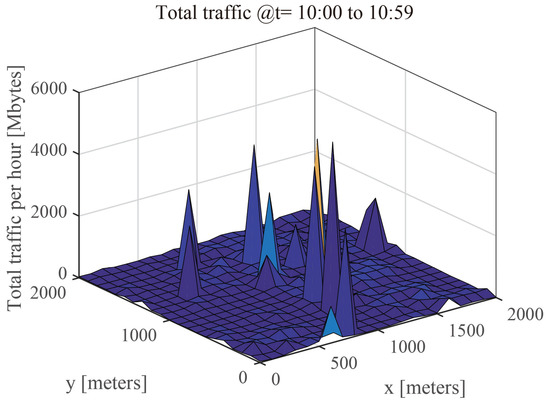
Figure 1.
Sample of spatial distribution of measured traffic in ODC [27].
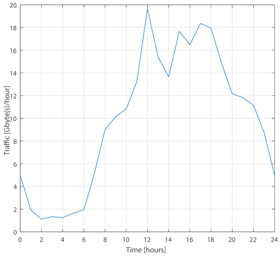
Figure 2.
Measured traffic’s daily time variation [27].
2.2. Network Architecture and System Models
For such environment like ODC, it is essential to deploy at hotspot areas a number of mmWave SC-BSs (or APs) overlaid on the current macro cells to effectively offload traffic, especially in peak hours as stated in [5]. However, introducing more SC-BSs will incur higher CAPEX (capital expenditures) and OPEX (operating expenses). Self-backhauling i.e., employing the same mmWave bands of access for backhaul can circumvent this issue since it radically avoids deployment cost of wired backhaul such as optical fiber or Ethernet cable. In addition, another benefit of mmWave meshed backhaul in reducing OPEX is its flexibility to reallocate backhaul resources via beam switching, multi-route multiplexing and deactivation of unused wireless interfaces [28]. Such functionalities are especially suitable for the time-variant and spatially non-uniform traffic occured in ODC. Fortunately, such flexible control of the mmWave meshed network can be done easily over out-band control plane (C-plane) e.g., LTE [29] owing to the maturity of nowadays SDN technologies.
2.2.1. System Architecture
Figure 3 depicts the system architecture of our considered self-backhauling mmWave overlay HetNet. We consider C/U splitting such that the C-plane is responsible by the conventional Long Term Evolution (LTE) macro cell. In other words, context information e.g., users’ location, movement, traffic demand and also dynamic configuration of wireless backhaul are monitored and controlled via the macro cell. On the other hand, downlink data communication (U-plane) are done via either conventional 3-sectored LTE macro cell or novel mmWave SC-BSs assuming UEs’ dual access connectivity. It is noted that uplink data communications are out of scope of this paper. For the downlink data communications, the LTE macro BS is considered as the only information source of the whole network, which works as the 6-sectored gateway (GW) of all other mmWave SC-BSs which are connected to the gateway via multi-hop communications over the mmWave meshed backhaul (Multi-hop communication incurs delay, which might be an issue for critical applications requiring ultra-low latency. On the other hand, our measurement result e.g., shown in Section 3.1 reveals a millisecond order of delay per hop, or ten of millisecond order of accumulated delay per 10 hops. Such delay is not so critical for normal eMBB applications with delay budget higher than 50 ms [16]. Although URLLC applications are out of scope of this paper, Multi-Access Edge Computing (MEC) technology can be added on top of the proposed network architecture to circumvent critical delay [30]. Other low latency and low data rate applications can be supported by conventional LTE macro.).
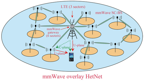
Figure 3.
Self-backhauling mmWave overlay HetNet.
2.2.2. IEEE802.11ad Based mmWave Meshed Backhaul
As depicted in Figure 3, we consider IEEE802.11ad based mmWave meshed backhaul for ODC. The mmWave SC-BSs overlaid on conventional macro cell are assumed to have multiple IEEE802.11ad based wireless interfaces for either purposes of access or backhaul. According to [31], the band is divided to 4 channels. This paper assumes access and backhaul links, each use 2 channels to avoid their mutual interference. Since access and backhaul interfaces are usually co-located, intra-channel interference avoidance via very high directivity antenna or other non-linear methods to reduce loop interference will incur high cost and thus is out of scope of this paper.
This paper also assumes that backhaul interfaces of SC-BSs are located e.g., on streets’ lamp posts such that Line of Sight (LoS) condition is guaranteed. Practical deployment is tackled in [32] and thus is out of scope of this paper. To overcome the high path loss issue, this paper assumes high gain antennas are employed at both transmit and receive sides of the mmWave backhaul link. Moderate link distance in the order of 100m is also considered. Furthermore, multi-hop communication is also adopted for SC-BSs which cannot communicate directly with the mmWave GW [25].
As mentioned above, the GW located at the macro BS can be connected to other SC-BSs either directly or indirectly in a multi-hop manner, which enables adaptive topology formation of meshed backhauling via beam switching. In addition, path loss attenuation can also be overcome via multi-hop relay since the weaken signals are re-boost at each hop of relay. For the sake of simplicity, this paper assumes relay links between mmWave backhaul interfaces can only be established if and only if their link budgets are sufficient to support the highest data rate defined in IEEE802.11ad standard [31]. This assumption also facilitates the realization of a homogeneous backhauling rate for ease of analysis.
2.3. Traffic Adaptive Mesh Construction
This paper considers a dynamic construction of mmWave meshed backhaul network taking into account both energy consumption and traffic delivery successful rate. For the first purpose, it attempts to deactivate as many as possible unnecessary mmWave SC-BSs (which are also called Access Points (APs) or a node in this paper). For the second purpose, the remaining activated SC-BSs should efficiently construct a traffic delivery meshed network to fulfill UEs’ traffic demands. For such objective function, this paper employs a similar heuristic approach as [25], which involves the following three steps to avoid solving an NP-hard problem which requires the optimization of both ON/OFF status of all mmWave interfaces and multi-hop backhaul path for load balancing.
2.3.1. Initial ON/OFF Status Selection
The step determines tentatively ON/OFF status of each SC-BS with the goal to reduce the mmWave meshed backhaul network’s power consumption as much as possible. For that purpose, under the constraint of UEs’ traffic demand, we attempt to offload as much traffic as possible to the LTE macro cell whose available bandwidth is restricted by . As a consequence, mmWave SC-BSs without connecting UEs via U-plane can be efficiently deactivated. Let us assume each UE has the closest mmWave SC-BS working as its anchored AP. The anchored SC-BS i.e., then has an aggregated traffic demand as the summation of all traffic demand of all UEs in this anchored AP. The required LTE bandwidth to accommodate such that can be deactivated, can be then approximately given by , where is the effective average SINR (Signal to Interference and Noise Ratio) of signals from LTE macro BS to the SC-BS assuming merely path loss attenuation, knowing that interference come from the other macro cell BSs. At this step, the determination of tentative ON/OFF status of SC-BS turns into the determination whether should be offloaded to LTE (if there is enough resource) or otherwise mmWave SC-BS. Let us denote as the former state that is accommodated by the k-th sector of the LTE macro BS, the optimization problem can be solved separately for each sector of the macro LTE as follows:
where denotes the cardinality of the set . As a consequence, if , the SC-BS can be deactivated for power consumption reduction. Otherwise i.e., , all the 3 sectors of the SC-BS will be turned on.
2.3.2. Initial Path Creation for Backhaul Network
The goal of this step is to create multi-hop paths from each sector of the mmWave GW to relay traffic to the mmWave SC-BSs via activated mmWave backhaul interfaces determined in previous step. Using load balancing approach, we determine such routes by solving the following linear programming problem:
where the number of SC-BSs and the number of sectors of GW are denoted by and respectively. Thus, the total number of flow equals the product of these. stacks the amount of load to be transferred from a sector of the mmWave GW to a SC-BS. weights the number of relay hop from GW against . stacks the summation of traffic load transfered via each sector of the mmWave GW. Similarly, stacks the total traffic supply to each SC-BS, expresses the ON/OFF state predetermined in the previous step. stacks all the traffic demands of each SC-BS. is a mapping matrix between and . Similarly, is a mapping matrix between and . The objective function is to find the optimal load balance with as small as possible number of hops from the GW (to reduce latency) under three constraints. The first constraint Equation (1) guarantees that the traffic transferred via each sector of the mmWave GW should not exceed the sector’s capacity. The second constraint Equation (2) ensures that the supply traffic to each SC-BS should higher than the total traffic load of that SC-BS to satisfy UEs’ demands. Finally, the third constraint Equation (3) assures that non-negative value of traffic load. From solving for , we can get the optimal combination of traffic load between multiple sectors of the mmWave GW working as the sources of information and all the SC-BS working as the sinks of information.
2.3.3. Reactivation and Path Creation for Isolated SC-BSs
The first step of this algorithm does not guarantee the connectivity of SC-BSs to the mmWave GW. Since there might exist isolated SC-BSs who cannot connect with the mmWave GW through multi-hop relay due to the deactivation of the surrounding SC-BSs, it is necessary to reactivate backhaul interfaces of certain SC-BSs which had been deactivated in the first step, to work merely as the relay nodes for isolated SC-BSs. After identifying isolated SC-BSs which have no parental nodes already attaining connectivity with the GW, the algorithm searches for shortest paths between the isolated SC-BSs and the non-isolated SC-BSs. The optimal combination of such shortest paths is found exhaustively to ensure the smallest number of SC-BSs on the determined shortest paths to be reactivated. H. Ogawa et al. [25] explained details of this heuristic approach.
For summary, the first step roughly decides the activation of SC-BSs in hotspot areas while traffic at sparse area is offloaded to the LTE macro BS. The second step performs a load balancing between multiple sectors at mmWave GW and activated SC-BSs while attempting to guarantee UEs’ traffic demand. One important characteristic of the loads optimized in this step is that it allows multiple route multiplexing from different sectors of the mmWave GW to supply backhaul resources to hotspot areas with densely concentrated traffic. In other words, a SC-BS can even support a volume of traffic larger than that can be provided by a single mmWave GW sector. Such functionalities will be tested in our testbed explained in the next section.
Employing SDN technology is suitable for realizing the aforementioned 3-step algorithm. Although the functions of SDN technology vary widely, route control functionality can be utilized for dynamic construction of mesh networks.The control signaling are performed in an out-band manner e.g., over LTE macro cell. Such mechanism is explained in details below.
2.4. C-plane for SDN-Based Mesh Construction
Dynamic control in the conventional wireless mesh network was mainly based on the IEEE 802.11s standard or OLSR (Optimized Link State Routing) protocol. However, in this in-band method as depicted in Figure 4, since C-plane and U-plane share the same media to optimize the network, it may take several tens of seconds to several hundreds of seconds to accomplish a phase of optimization. The performance is further worsen when the size of the network increases and prevents dynamic control of a large scale wireless mesh network like our considered scenario. More specifically, in-band C-plane (using the same small coverage mmWave interface) yields unwanted control latency due to multi-hop communications to the controller, that reduces the resiliency of the networks in adaptation to environment changes significantly. Therefore, this paper employs out-of-band C-plane via direct communication with a large coverage LTE macro as depicted in Figure 5. On contrary to the in-band method, the out-of-band C-plane make the networks more resilient to environment changes owing to faster adaptation rate incurred from lower control latency. It would be more beneficial for SDN technology [33] to be employed in our considered ODC scenario. In fact, the SDN control of the wireless mesh network based on the out-of-band control plane can succeed in making the network more resilient to environment changes as will be shown in Section 3.2.
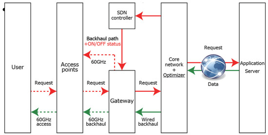
Figure 4.
Conventional C-plane (User centric ON).
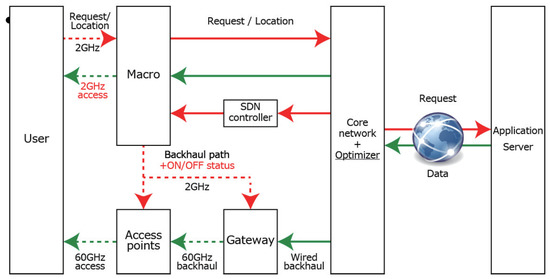
Figure 5.
Proposed out-of-band C-plane (Network centric ON).
As explained above, the dynamicity of the traffic distribution thus the dynamicity of the meshed network transformation, necessitates the separation of the C-plane (control plane) and the U-plane (data plane) into different frequency bands. Specifically, this paper adopts out-of-band C-plane via macro LTE to support higher C-plane’s delay requirement in our study. Here, the macro base station’s carrier of 2 GHz band is adopted as the frequency band used for the control plane to guarantee a large coverage in order to centrally manage context information necessary for the C-plane. Also, in general, the load of the control plane is sufficiently smaller than that of the U-plane, so narrow band communications at 2 GHz band is sufficient.
Detailed explanation about the signaling over the adopted out-of-band C-plane for operating the functionality of the SDN controller is depicted in Figure 6, where MANO (Management and Network Orchestration) denotes the controller. The controller located behind the C-plane has three functionalities: context management framework, an optimizer and a SDN controller. The context management framework will gather information about traffic distribution etc. The meshed network structure is optimized by the optimizer. SDN controller sends commands to AP and UE via the C-plane downlink to establish the meshed network as well as the association of UE to a SC-BS in a deterministic way. Detailed interaction between different entities in this figure is explained below. First, the user’s request e.g., traffic demand is reported to the network via the 2 GHz band C-plane uplink. Furthermore, the network can predict the user’s U-plane radio condition as well as position based on measured RSSI (Received Signal Strength Indicator) and GPS (Global Positioning System) etc. Nowadays, there are rigorous research activities to enhance accuracies of such context information and details are our of scope of this paper. The context management framework inside the controller gather such context information i.e., traffic demands, UEs’ positions etc. Based on the information, the optimizer analyzes the traffic load of the entire network and calculates the optimum backhaul path as explained in Section 2.3. Again, based on the optimization results, the optimum backhaul path information is then delivered as the commands from the SDN controller to all APs using the 2 GHz band C-plane downlink. Finally, the data from the application server is transferred to the host AP accommodating specific users via the constructed mmWave meshed backhaul. In addition, the method of performing power control using an out-of-band C-plane is called “network centric ON” method and that using the conventional in-band C-plane is called “user centric ON” in this paper.
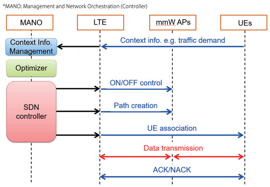
Figure 6.
Functionalities of the controller (MANO) and signaling over out-of-band C-plane.
2.5. Numerical Results
This section presents numerical analysis results of the proposed traffic adaptive construction of mmWave meshed backhaul. In our simulation, we deployed several macro cells with inter-site distance (ISD) of 500 m in the 4 square kilometer areas depicted in Figure 1. Only one macro cell at the center is selected for evaluation and the other surrounding ones work as LTE interference sources. Simulation parameters are summarized in Table 1.

Table 1.
Simulation parameters.
Examples of the formed mmWave meshed networks are shown in Figure 7. As there are few users in the evaluation area at 3 AM, only a few mmWave SC-BSs are activated. In this case, since there are enough resource blocks in the LTE, most of the users are connected to the macro BS, while users with very high traffic demand at the right-bottom activate SC-BSs. On the other hand at 3 PM, a hotspot appears in the upper-left zone. We can see some backhaul links formed from gateway to the hotspot, showing the effectiveness of the proposed traffic adaptive construction of mmWave meshed backhaul against the locally intensive traffic.
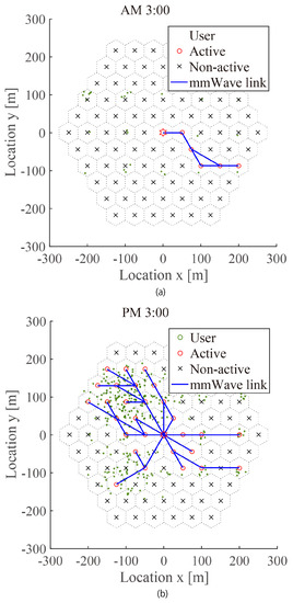
Figure 7.
Example of traffic adaptive formation of mmWave meshed backhaul. (a) Formed mmWave meshed network at AM 3:00. (b) Formed mmWave meshed network at PM 3:00.
This effect is evaluated quantitatively by an indicator called satisfaction ratio. It is defined as the portion of demanded traffic is completely delivered to UEs through the mesh networks. In our evaluation, we considered three mechanisms for decision of ON/OFF status of SC-BSs. The proposed approach in this paper is called “Network centric ON”. For comparison, “User centric ON” scheme deactivates a SC-BS if and only if there is no UEs within its vicinity. It means that even if there is only one UE selects the AP as the anchored SC-BS, it will not be deactivated. The other comparison scheme is called “Always ON”, which literally activates all SC-BSs permanently. Our evaluation result shows that all the three schemes can successfully deliver all demanded traffic towards UEs. In other words, our proposed “Network centric ON” scheme is equivalent to the other conventional schemes in terms of network capacity, regardless of many deactivated SC-BSs. It is owing to the capability of route multiplexing of the proposed scheme especially against intensive traffic time. Therefore, without sacrificing network performance, the proposed scheme is more energy-efficient than the other comparison schemes.
The analysis of power consumption is shown in Figure 8. The figure shows the performance of total power consumption against dynamic traffic variation throughout a day. The power consumption includes both of the access and backhaul, which is defined as , where and represent the number of ON sectors and that of OFF sectors of the mmWave SC-BS respectively. From the figure, the effectiveness of the traffic and energy management algorithm is obvious especially in midnight. Roughly speaking, the proposed scheme reduces the energy consumption by a factor of half.
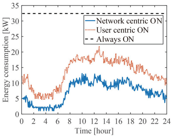
Figure 8.
Numerical performance of total energy consumption.
3. SDN-Based Implementation As A Proof-Of-Concept
A testbed is constructed to verify the effectiveness of our proposed scheme. The testbed architecture is explained in Section 3.1. Using the testbed, several experiments are conducted. First, Section 3.2 shows that the testbed validly works in real environment with its resiliency functionality. In the next step, we apply the proposed dynamic mesh construction method to the testbed in Section 3.3 and preliminary results are achieved to demonstrate the effect of route multiplexing of the proposed algorithm against intensive traffic. It should be noted that due to the limitation in the scale of the testbed, measurements on the effect of reducing power consumption through dynamic ON/OFF remain as our future works.
3.1. SDN-Based Mesh Backhaul Architectural Principles
As a proof of concept for a SDN-based mmWave mesh network, we deploy a testbed environment composed by 4 mesh nodes and an additional node, responsible for the SDN controller functionalities. Each node is a Gigabyte GB-BKi7HA-7500 mini-PC, running Ubuntu 16.04 LTS with Linux kernel version 4.4.0-36-generic. Each mini-PC has 16 GB RAM and a 3.5 GHz Intel processor. In addition, we install 2 IEEE 802.11ad WiGig dongles from Panasonic Inc. Japan on each mesh node. The dongles are configured with MCS9 (Modulation and Coding Scheme), whose theoretical physical layer (PHY) rate can be referred to [31]. In addition, they can only operate on the two middle channels e.g., #2 and #3, among the 4 channels of IEEE 802.11ad.
As depicted in Figure 9, Node 1 (N1) has a link with Node 2 (N2) in channel #2, and a second link with Node 3 (N3) in channel #3. Additionally, Node 4 (N4) is connected to N2 in channel #3 and to N3 in channel #2. Here, the channels are switched to avoid inter-link interference. For each link, one end has the IEEE 802.11ad module configured to operate in AP (access point) mode, while the other is in UE (station) mode. A corresponding photo of the constructed testbed is shown in Figure 10.
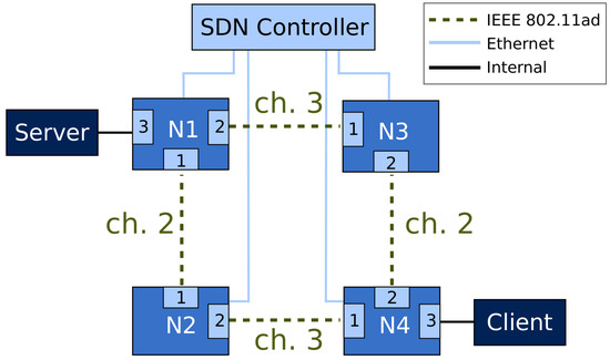
Figure 9.
Used testbed topology.
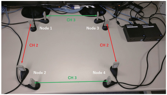
Figure 10.
Photo of mmWave meshed network testbed.
To enable the management of the mesh nodes through the SDN controller we install Open vSwitch (OVS) [34] 2.7.0 as an OpenFlow-enabled software switch, and added the WiGig interfaces as switch ports. The built SDN controller is based on OpenDaylight (ODL) [35] and features modules that support the installation of OpenFlow forwarding rules through its Southbound API (Application Programming Interface), along with a Northbound API which can be used for issuing configuration commands from network management applications. The communication between the controller and the mesh nodes is performed through an out-of-band Ethernet channel.
Given our testing topology, and for the easiness of understanding the upcoming results, we present the maximum throughput and latency values with no background traffic on 1 and 2 hops in Table 2. In this baseline test, User Datagram Protocol (UDP) flows are generated. The ping command is used to get a rough estimation of the RTT (Round Trip Time). The result shows that the maximum throughput of 1.51 Gbps that the WiGig devices can provide is achieved, even for the case of 2 hops since two orthogonal channels are assigned for each hop to prevent interference. The RTT for the 2-hop case is naturally higher than that of the 1-hop case due to multi-hop communication [36].
Table 2.
Baseline latency and maximum throughput values.
3.2. MmWave Mesh Backhaul Resiliency
Due the physical properties of mmWave links, often a network can suffer from temporary link failures due to loss of connectivity, caused by obstacle blockage, for example. While long-lasting link failures can be detected and repaired by the SDN controller (by computing a new network path and re-routing the traffic, for example), short failures might not be able to be promptly detected by the controller or, by the time the controller detects the failure and computes a new network configuration, the disruption caused by the failure can already be over.
For short-lasting link failures, the network should be able to react locally and re-route its traffic to an active link. OpenFlow (OF) groups allow the specification of different instruction sets to deal with a single forwarding rule (action buckets). In addition, it is possible to choose different group types, allowing different criteria for selecting the used bucket. As a solution to provide resiliency when multiple links are available, a fast-failover (FF) group type can be used. When using FF, a packet is sent to the first live bucket. The criteria for deciding the liveness state of each bucket is then implementation-specific. OVS allows the usage of the Bidirectional-forwarding detection (BFD) protocol [37] to monitor the managed links’ states. With BFD, the link status can be monitored by sending probe packets on each link periodically. The port is considered down if 3 packets are not received. The probing time can be adjusted, taking around 3 times the configured interval to notify a port as down. Thus, a shorter BFD monitoring interval yields a faster detection of down states, at the cost of increased traffic and processing overhead. In opposite, a high interval is not suitable to promptly detect a failure [38,39]. K. Nguyen et al. [40] explored the robustness in OF-based Software-defined Wireless Networks. This work proposed a multi-path aware solution for the OF controller channel. Experimental work with SDN in wireless and fast-failover using BFD had been reported in [41], where the recovery times of IEEE 802.11ac links is measured, by using different BFD intervals. Resiliency with BFD over mmWave bands is covered within emulated environments in [39,42], and with testbed measurements in [26].
In order to investigate the behavior of BFD with different monitoring intervals, we evaluate its behavior when applying different amounts of data traffic in the used links (between 10 Mbps and 1.5 Gbps), while varying the BFD interval between 1 ms and 20 ms. For that, we generate traffic from N1 to N4 by using an internal OVS network interface, using iperf [43] as a traffic generator, by creating an UDP flow with 7882 byte packets with the desired bitrate during 10 s. The evaluation of TCP (Transmission Control Protocol) over mmWave links brings additional set of parameters to configure (e.g., congestion control protocol), increasing the evaluation’ s complexity, which is out of the scope of this work. The used topology allows the usage of 2 different link-disjoint paths, N1-N2-N4 (path 1) and N1-N3-N4 (path 2). To monitor the link state, we configure BFD between the interfaces connecting N1-N2 and N1-N3, respectively. In addition, the network throughput is measured with tshark, by capturing incoming traffic on both its mmWave interfaces.
The results for the different measured throughput values in the traffic client are presented in Figure 11. For all the used UDP flow rates, it is possible to observe a significant throughput degradation when using 1, 3 and 5 ms BFD monitoring intervals. Contrariwise, the throughput always reached the desired values with the 10, 15 and 20 ms intervals. As the detection intervals are decreased, the amount of monitoring BFD packets increase and, at the same time, the packet processing latency thresholds decrease (e.g., approximately 3ms when using a 1 ms interval). When adding data traffic in the same interface used to monitor link failures, the monitoring packets are subject to additional processing or queuing delays, which can negatively affect the delivery of monitoring packets within the allowed intervals, causing false positive link failures [39]. This phenomenon is illustrated in Figure 12, where the data rate on both interfaces of N1 is plotted over an iteration using an 1 Gbps flow, using an 1 ms and 20 ms BFD intervals. With 1 ms, whenever the primary interface of N1 is falsely set as down, often it is possible to transition to its second interface (with the cost of a short packet transmission disruption). However, it is also possible that both interfaces can be falsely set as down simultaneously, causing a total failure on the data transmission. With the 20ms BFD interval, there are no interruptions on the ongoing traffic, as the higher interval allows a higher protection against eventual delay surges in the monitored links. In conclusion, the 10, 15 and 20 ms BFD detection intervals were selected as a configuration baseline for upcoming experiments using BFD fast failover.
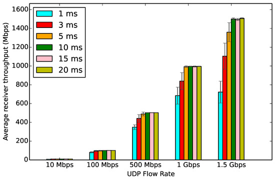
Figure 11.
Measured throughput in N4 with different BFD intervals.
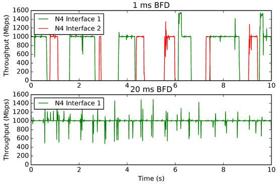
Figure 12.
Throughput over time for an 1 Gbps UDP flow.
The second main goal of this evaluation is focused on the accessing how fast can a link recover from a failure, when using the following resilience mechanisms:
- Fast-Failover reconfiguration: Initially both N1 interfaces are alive, staying active during the first 5 s, with network traffic routed through the first active group bucket i.e., N1-N2 link. The N2 interface of the N1-N2 link is then disabled by using ifconfig command after 5 s, and re-enabled after 1 s, leaving all the N1 links active until the end of the experiment. With this approach, the network traffic is sent through path 1 (N1-N2-N4), until BFD changes N1’s interface state to down, and consequently sending packets through path 2 (N1-N3-N4) due to the FF configuration. The usage of path 1 usage is then resumed when the disabled interface is reactivated. A 10, 15 and 20 ms BFD monitoring intervals were used in this scenario;
- SDN Controller triggered reconfiguration: Flow forwarding rules are initially installed, forwarding the traffic from N1 to N4 through N2. After 5 s, the controller modifies the forwarding rules rules in N1 and N4 to forward packets via N3. The N2 interface of the N1-N2 is then disabled during 1 s. The controller sets all the flows to the initial state after the N2 interface is reactivated. These experiments can represent a scenario where the controller has knowledge of an upcoming failure, reconfiguring the network before it happens (e.g., prediction of link disruption due to obstacle blockage).
- No Failover: Similar initial forwarding rules are installed as previously described (traffic between N1 and N4 is forwarded through N2). However, when the N2 interface is disabled, no reconfiguration operation is triggered.
For every scenario, when having a 1 Gbps flow transmitted from N1 to N4, we measured the packet transmission interruption time after the link failure. It corresponds to the interval without any received packets in N4 after the N2 interface is disabled. Table 3 presents the average interruption times. With Fast Failover and BFD, the mean values are almost 3 times the configured interval on all the scenarios. In some occasions, the internal BFD timer starts with the last echo packet sent before the link failure, resulting in values shorter than 3 times the BFD interval. Without using any mechanisms like failover, the average interruption time reaches 1.2 s approximately for every scenario, which include the link down period of 1 s. The additional delay is due to the overhead the interface needs to take to re-establish connectivity with N1 [41]. The transition from one interface to another was almost instantaneous after receiving the OF flow installation command when using the SDN controller for reconfiguration. It guarantees that the existing traffic was not forwarded through an inactive link.
Table 3.
Interruption time against different resilience mechanisms.
3.3. MmWave Mesh Backhaul Route Multiplexing Against Intensive Traffic
The dedicated C-plane design for the testbed in this section is provided in Figure 13. In this experiment, a virtual user is created by VUM (Virtual User Manager) and requests data from the server stochastically. The distribution of the instantaneous traffic demand follows a Gamma distribution as in [16], with the average traffic value of 25 Mbps. The data transfer is performed through the data plane e.g., WiGig link. Since macro LTE is not available, the C-plane for SDN orchestration is performed via Ethernet instead. The orchestrator calculates the optimum route of the mesh backhaul network and transfers it to the OVS of each small cell base station via the SDN controller.
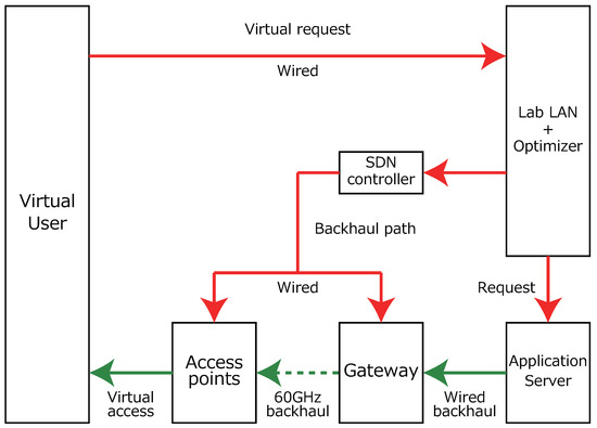
Figure 13.
System configuration of each AP.
In order to verify the operation of our proposed SDN-based meshed network construction over the testbed, the following experiment is conducted. We have set up 100 virtual users distributed in the implemented network, of which is distributed to AP2 (N2) and the remaining is equally distributed to AP3 (N3) and AP4 (N4). By controlling the ratio , we can simulate the situation of dense hotspot at AP2 (N2), where route multiplexing is required. To show the benefit of the proposed method, the experiments were conducted in two scenarios with and without backhaul route multiplexing.
The results of verification in the range of are shown in Figure 14. Blue line and orange line show the results of with and without backhaul route multiplexing respectively. In the case of none, the system satisfaction degree defined as the ratio of the total delivered traffic over the total demanded traffic decreases as more users are concentrated at AP2 (N2). On the other hand, we are able to maintain a satisfaction level of 97% to 98% when our proposed method is applied. The reason why it cannot reach perfect delivery is due to the UDP protocol employed, where a part of failed packets is discarded without being retransmitted.
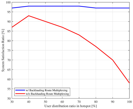
Figure 14.
Validation of the proposed method via experimental results.
3.4. Future Works
In future works, we plan to conduct outdoor experiments using the developed testbed. More measurement results in realistic environments with different experimental conditions e.g., using TCP flows, will be derived to investigate other functionalities of the testbed including network construction time, power consumption etc. A part of our ongoing investigation will be presented in [44].
4. Conclusions
This paper proposed a novel method to control mmWave meshed backhaul for efficient operation of mmWave overlay 5 G HetNet through SDN technology. Our algorithm was featured by two functionalities, i.e., backhauling route multiplexing for overloaded mmWave SC-BSs and dynamic deactivation of SC-BSs for underloaded spot. The effectiveness of the proposed meshed network was confirmed by both numerical analyses and experimental results. Numerical results showed that the proposed algorithm can cope with the locally intensive traffic and reduce energy consumption. Especially, we were first to establish a WiGig device based testbed to demonstrate the proposed method. Preliminary measurement results confirmed the proposed dynamic formation of the meshed network’s efficiency.
Author Contributions
Conceptualization, G.K.T. and K.S.; Methodology, H.O. and R.S.; Validation, H.O. and R.S.; Investigation, H.O., R.S. and G.K.T.; Data Curation, M.N.; Writing–Original Draft Preparation, G.K.T.; Writing–Review & Editing, G.K.T.; Visualization, H.O., R.S. and G.K.T.; Supervision, K.S. and A.K.; Project Administration, K. Sakaguchi and A. Kassler; Funding Acquisition, K.S. and A.K.
Funding
This research was funded by the European Commission (EC) H2020 and the Ministry of Internal affairs and Communications (MIC) in Japan under grant agreements No. 723171 5G-MiEdge in EC and {0159-0077, 0155-0074} in MIC. Parts of this work have been also funded by the Scandinavia-Japan Sasakawa Foundation and the Knowledge Foundation of Sweden through the project SOCRA.
Acknowledgments
The authors would like to thank the anonymous reviewers for their valuable comments and suggestions to improve the quality of the paper.
Conflicts of Interest
The authors declare no conflict of interest.
References
- Study on New Radio Access Technology: RF and Co-Existence Aspects; Technical Report TR 38.803 (RNA4); 3GPP: Sophia Antipolis CEDEX, France, May 2016.
- Sakaguchi, K.; Sampei, S.; Shimodaira, H.; Rezagah, R.; Tran, G.; Araki, K. Cloud Cooperated Heterogeneous Cellular Networks. In Proceedings of the 2013 International Symposium on Intelligent Signal Processing and Communication Systems, Naha, Japan, 12–15 Novemebr 2013; pp. 787–791. [Google Scholar]
- Bai, T.; Heath, R.W. Coverage and rate analysis for millimeter wave cellular networks. IEEE Trans. Wirel. Commun. 2014, 14, 1100–1114. [Google Scholar] [CrossRef]
- Singh, S.; Kulkarni, M.; Ghosh, A.; Andrews, J. Modeling and analyzing millimeter wave cellular systems. IEEE Trans. Commun. 2017, 65, 403–430. [Google Scholar]
- Sakaguchi, K.; Tran, G.; Shimodaira, H.; Nanba, S.; Sakurai, T.; Takinami, K.; Siaud, I.; Strinati, E.; Capone, A.; Karls, I.; et al. Millimeter-wave evolution for 5G cellular networks. IEICE Trans. Commun. 2015, 98, 388–402. [Google Scholar] [CrossRef]
- Sakaguchi, K.; Haustein, T.; Barbarossa, S.; Strinati, E.; Clemente, A.; Destino, G.; Pärssinen, A.; Kim, I.; Chung, H.; Kim, J. Where, when, and how mmwave is used in 5G and beyond. IEICE Trans. Electron. 2017, 100, 790–808. [Google Scholar] [CrossRef]
- Gangakhedkar, S.; Cao, H.; Ali, A.; Ganesan, K.; Gharba, M.; Eichinger, J. Use cases, requirements and challenges of 5G communication for industrial automation. In Proceedings of the International Conference on Communications (ICC), Kansas City, MO, USA, 20–24 May 2018. [Google Scholar]
- Jaber, M.; Imran, M.; Tafazolli, R.; Tukmanov, A. 5G backhaul challenges and emerging research directions: A survey. IEEE Access 2016, 4, 1743–1766. [Google Scholar] [CrossRef]
- Peters, S.W.; Heath, R.W., Jr. The future of WiMAX: Multihop relaying with IEEE 802.16j. IEEE Commun. Mag. 2009, 47, 104–111. [Google Scholar] [CrossRef]
- Pi, Z.; Khan, F. An introduction to millimeter-wave mobile broadband systems. IEEE Commun. Mag. 2011, 49, 101–107. [Google Scholar] [CrossRef]
- Rappaport, T.; Sun, S.; Mayzus, R.; Zhao, H.; Azar, Y.; Wang, K.; Wong, G.; Schulz, J.; Samimi, M.; Gutierrez, F. Millimeter wave mobile communications for 5G cellular: It will work! IEEE Access 2013, 1, 335–349. [Google Scholar] [CrossRef]
- Rappaport, T.S.; Xing, Y.; MacCartney, G.R., Jr.; Molisch, A.F.; Mellios, E.; Zhang, J. Overview of millimeter wave communications for fifth-generation (5G) wireless networks: With a focus on propagation models. IEEE Trans. Antennas Propag. 2017, 65. [Google Scholar] [CrossRef]
- Karttunen, A.; Molisch, A.F.; Hur, S.; Park, J.; Zhang, C.J. Spatially consistent street-by-street path loss model for 28-GHz channels in micro cell urban environments. IEEE Trans. Wirel. Commun. 2017, 16, 7538–7550. [Google Scholar] [CrossRef]
- Maltsev, A.; Sadri, A.; Pudeyev, A.; Bolotin, I. Highly directional steerable antennas: High-gain antennas supporting user mobility or beam switching for reconfigurable backhauling. IEEE Veh. Technol. Mag. 2016, 11, 32–39. [Google Scholar] [CrossRef]
- Sakaguchi, K.; Tran, G.K.; Ogawa, H. mmWave meshed network with traffic and energy management mechanism. In Proceedings of the 18th IEEE International Workshop on Signal Processing Advances in Wireless Communications (SPAWC), Sapporo, Japan, 3–6 July 2017. [Google Scholar]
- Tran, G.; Shimodaira, H.; Sakaguchi, K. User satisfaction constraint adaptive sleeping in 5G mmwave heterogeneous cellular network. IEICE Trans. Commun. 2018, 101. [Google Scholar] [CrossRef]
- Shimodaira, H.; Tran, G.; Araki, K.; Sakaguchi, K.; Namba, S.; Hayashi, T.; Konishi, S. Cell Association Method for Multiband Heterogeneous Networks. In Proceedings of the 2014 IEEE 25th Annual International Symposium on Personal, Indoor, and Mobile Radio Communication (PIMRC), Washington, DC, USA, 2–5 September 2014. [Google Scholar]
- Scott-Hayward, S.; Garcia-Palacios, E. Channel Time Allocation PSO for Gigabit Multimedia Wireless Networks. IEEE Trans. Multimedia 2014, 16, 828–836. [Google Scholar] [CrossRef]
- Pyo, C.W.; Harada, H. Throughput analysis and improvement of hybrid multiple access in IEEE 802.15.3c mm-wave WPAN. IEEE J. Sel. Areas Commun. 2009, 27, 1414–1424. [Google Scholar]
- Singh, S.; Kulkarni, M.; Ghosh, A.; Andrews, J. Tractable model for rate in self-backhauled millimeter wave cellular networks. IEEE J. Sel. Areas Commun. 2015, 33, 2196–2211. [Google Scholar] [CrossRef]
- Liu, Y.; Niu, Y.; Li, Y.; Zeng, M.; Han, Z. Exploiting Multi-Hop Relay to Achieve Mobility-Aware Transmission Scheduling in mmWave Systems. In Proceedings of the 2018 IEEE International Conference on Communications (ICC), Kansas City, MO, USA, 20–24 May 2018. [Google Scholar]
- Du, J.; Onaran, E.; Chizhik, D.; Venkatesan, S.; Valenzuela, R. Gbps user rates using mmWave relayed backhaul with high gain antennas. IEEE J. Sel. Areas Commun. 2017, 35, 1363–1372. [Google Scholar] [CrossRef]
- Kulkarni, M.; Andrews, J.; Ghosh, A. Performance of dynamic and static TDD in self-backhauled millimeter wave cellular networks. IEEE Trans. Wireless Commun. 2017, 16, 6460–6478. [Google Scholar] [CrossRef]
- Mesodiakaki, A.; Zolab, E.; Santos, R.; Kassler, A. Optimal user association, backhaul routing and switching off in 5G heterogeneous networks with mesh millimeter wave backhaul links. Ad Hoc Netw. 2018, 78, 99–114. [Google Scholar] [CrossRef]
- Ogawa, H.; Tran, G.K.; Sakaguchi, K.; Haustein, T. Traffic Adaptive Formation Algorithm for mmWave Meshed Backhaul Networks. In Proceedings of the International Conference on Communications (ICC), Paris, France, 21–25 May 2017. [Google Scholar]
- Santos, R.; Ogawa, H.; Tran, G.K.; Sakaguchi, K.; Kassler, A. Turning the Knobs on OpenFlow-Based Resiliency in mmWave Small Cell Meshed Networks. In Proceedings of the IEEE GLOBECOM Workshops 2017, Singapore, 4–8 December 2017. [Google Scholar]
- Tran, G.; Shimodaira, H.; Rezagah, R.; Sakaguchi, K.; Araki, K. Practical evaluation of on-demand smallcell ON/OFF based on traffic model for 5G cellular networks. In Proceedings of the Wireless Communications and Networking Conference (WCNC), Doha, Qatar, 3–6 April 2016. [Google Scholar]
- Cai, S.; Che, Y.; Duan, L.; Wang, J.; Zhou, S.; Zhang, R. Green 5G heterogeneous networks through dynamic small-cell operation. IEEE J. Sel. Areas Commun. 2016, 34, 1103–1115. [Google Scholar] [CrossRef]
- Li, X.; Ferdous, R.; Chiasserini, C.; Casetti, C.; Moscatelli, F.; Landi, G.; Casellas, R.; Sakaguchi, K.; Chundrigar, S.; Vilalta, R.; et al. Novel Resource and Energy Management for 5G Integrated Backhaul/ Fronthaul (5G-Crosshaul). In Proceedings of the International Conference on Communications (ICC), Paris, France, 21–25 May 2017. [Google Scholar]
- Nishiuchi, H.; Tran, G.; Sakaguchi, K. Performance Evaluation of 5G mmWave Edge Cloud with Prefetching Algorithm. In Proceedings of the 2018 IEEE 87th Vehicular Technology Conference (VTC Spring), Porto, Portugal, 3–6 June 2018. [Google Scholar]
- Takinami, K.; Shirakata, N.; Kobayashi, M.; Urushihara, T.; Takahashi, H.; Motozuka, H.; Irie, M.; Shimizu, M.; Tomisawa, Y.; Takahashi, K. Design and Experimental Evaluation of 60GHz Multiuser Gigabit/s Small Cell Radio Access Based on IEEE 802.11ad/WiGig. IEICE Trans. Commun. 2016, 100, 1196–1205. [Google Scholar] [CrossRef]
- Nakamura, M.; Tran, G.; Sakaguchi, K. Interference Management for Millimeter-Wave Mesh Backhaul Networks. In Technical Report of IEICE TCSR; IEICE: Hakodate, Japan, 2018. (In Japanese) [Google Scholar]
- González, S.; Oliva, A.; Costa-Pérez, X.; Giglio, A.; Cavaliere, F.; Deiß, T.; Li, X.; Mourad, A. 5G-Crosshaul: An SDN/NFV control and data plane architecture for the 5G integrated fronthaul/backhaul. Trans. Emerg. Telecommun. Technol. 2016, 27, 1196–1205. [Google Scholar] [CrossRef]
- Pfaff, B.; Pettit, J.; Koponen, T.; Jackson, E.J.; Zhou, A.; Rajahalme, J.; Gross, J.; Wang, A.; Stringer, J.; Shelar, P.; et al. The Design and Implementation of Open vSwitch. Proceddings of the 12th USENIX Conference on Networked Systems Design and Implementation, Oakland, CA, USA, 4–6 May 2015; pp. 117–130. [Google Scholar]
- Medved, J.; Varga, R.; Tkacik, A.; Gray, K. Opendaylight: Towards a model-driven SDN controller architecture. In Proceedings of the 2014 IEEE 15th International Symposium on aWorld of Wireless, Mobile and Multimedia Networks (WoWMoM), Sydney, NSW, Australia, 19 June 2014. [Google Scholar]
- Ho, I.; Lam, P.; Chong, P.; Liew, S. Harnessing the High Bandwidth of Multiradio Multichannel 802.11n Mesh Networks. IEEE Trans. Mobile Comput. 2014, 13, 448–456. [Google Scholar] [CrossRef]
- Katz, D.; Ward, D. Bidirectional Forwarding Detection (BFD); IETF RFC 5880, June 2010. Available online: https://tools.ietf.org/html/rfc5880 (accessed on 1 July 2017).
- Van Adrichem, N.L.; Van Asten, B.J.; Kuipers, F.A. Fast recovery in software-defined networks. In Proceedings of the 2014 Third European Workshop on Software Defined Networks, London, UK, 1–3 September 2014. [Google Scholar]
- Vestin, J.; Kassler, A. Low frequency assist for mmWave backhaul-the case for SDN resiliency mechanisms. In Proceedings of the 2017 IEEE International Conference on Communications Workshops (ICCWorkshops), Paris, France, 21–25 May 2017. [Google Scholar]
- Nguyen, K.; Ishizu, K.; Murakami, H.; Kojima, F.; Yano, H. A Scalable and Robust OpenFlow Channel for Software Defined Wireless Access Networks. In Proceedings of the 2015 IEEE 82nd Vehicular Technology Conference (VTC Fall), Boston, MA, USA, 6–9 September 2015. [Google Scholar]
- Santos, R.; Kassler, A. Small Cell Wireless Backhaul Reconfiguration Using Software-Defined Networking. In Proceedings of the Wireless Communications and Networking Conference (WCNC), San Francisco, CA, USA, 19–22 March 2017. [Google Scholar]
- Vestin, J.; Kassler, A. Resilient SDN based small cell backhaul networks using mmWave bands. In Proceedings of the 2016 IEEE 17th International Symposium on A World of Wireless, Mobile and Multimedia Networks (WoWMoM), Coimbra, Portugal, 21–24 June 2016. [Google Scholar]
- Tirumala, A.; Qin, F.; Dugan, J.; Ferguson, J.; Gibbs, K. Iperf: The TCP/UDP Bandwidth Measurement Tool. 2015. Available online: http://dast.nlanr.net/Projects (accessed on 1 July 2017).
- Nakamura, M.; Santos, R.; Koslowski, K.; Nishiuchi, H.; Tran, G.; Sakaguchi, K. Performance Evaluation for Millimeter-wave Backhaul and Edge Cloud Networks. In Proceedings of the SmartCom 2018, Bangkok, Thailand, 30–31 October 2018; IEICE: Bangkok, Thailand. [Google Scholar]
© 2018 by the authors. Licensee MDPI, Basel, Switzerland. This article is an open access article distributed under the terms and conditions of the Creative Commons Attribution (CC BY) license (http://creativecommons.org/licenses/by/4.0/).