
Recent Developments in the Aerodynamic Heat Transfer and Cooling Technology of Gas Turbines Endwalls

Research Institute of Aerospace Technology, Central South University, Changsha 410012, China
*
Author to whom correspondence should be addressed.
Aerospace 2023, 10(8), 702; https://doi.org/10.3390/aerospace10080702
Submission received: 10 July 2023
/
Revised: 8 August 2023
/
Accepted: 8 August 2023
/
Published: 9 August 2023
(This article belongs to the Section Aeronautics)
Abstract
:With an increased inlet gas temperature and the homogenization of the combustion chamber outlet temperature, the endwalls of gas turbines are exposed to extremely high heat loads. The complex flow structure of turbine endwalls makes it difficult to cool some regions of the endwalls, which can easily cause endwall ablation, reducing turbine aerodynamic performance and threatening the turbine’s safe operation. In order to improve the cooling and aerodynamic performance of gas turbines, the flow structure, heat transfer and film cooling characteristics of endwalls are analyzed in depth in this paper. This paper summarizes and analyzes the development of the aerodynamic heat transfer and film cooling of gas turbine endwalls in terms of geometric structures and flow boundary conditions and also presents new research directions. Based on the literature, the development and challenge of turbine endwall film cooling are also discussed.
1. Introduction
The increase in aircraft engine thrust relies heavily on increasing the total exhaust gas temperature prior to entering the turbine vanes. Based on calculations, for every 55 °C increase in the total temperature of the turbine, with the engine size kept constant, the engine thrust can increase by approximately 10% [1]. Two primary solutions exist to address the challenges caused by high temperatures [2,3]. The first involves enhancing the material heat resistance through the development of high-performance, heat-resistant alloys and the manufacturing of single-crystal blades. The second solution entails the utilization of advanced cooling technologies, employing minimal amounts of cooling air to achieve an enhanced cooling efficiency. Future development directions include the use of artificial fiber-reinforced superalloys, directionally recrystallized oxide dispersion-reinforced alloys and new high-temperature-resistant materials.
The turbine inlet temperature increases by an average of 20 °C per year, while the resistance of the metal to the temperature increases by an average of 8 °C per year [1]. Therefore, even with the utilization of high-temperature-resistant materials, such as carbon–carbon composites in engine turbine components, the need for cooling cannot be completely eliminated. Advanced cooling technology enables high-temperature components to withstand higher operating temperatures, resulting in an increased engine longevity and reliability. Figure 1 depicts the schematic of a blade’s film cooling system.
To meet the requirements for low NOx emissions, the combustion chamber should have a more uniform temperature distribution along the vertical direction of the blade, resulting in an increase in the fluid temperature near the endwall. As a result, the heat load on the turbine endwalls sharply increases, necessitating high-efficiency endwall film cooling as an urgent requirement. Further studies are needed to examine the aerodynamic heat transfer and cooling characteristics of gas turbine endwalls to ensure the safe operation of gas turbines. Several researchers [1,5] have highlighted the significant influence of cooling structures on improving the cooling efficiency of gas turbines. The conventional cooling structures for gas turbine endwalls comprise discrete cooling film holes, cooling slots and the cooling of the passage gaps on the endwalls.
Complex three-dimensional flow structures on the endwalls, such as secondary flow phenomena, impede coolant coverage on the endwall [6]. Figure 2 depicts the distribution of vortex systems, including horseshoe, passage and corner vortices [7]. Holley et al. [8], based on experimental findings, observed a significant decrease in the boundary layer thickness downstream of the saddle point compared to upstream. This occurs because the fluid in the boundary layer downstream of the saddle point constantly moves towards the suction surface of the blade driven by the transverse pressure gradient. The presence of fluid viscosity and interactions between the boundary layer fluid near the endwall and the secondary flow result in aerodynamic losses on the endwall.
Recently, researchers have shown increased interest in the gas film coverage on the entire vane endwall, the discharge flow through the annular slot seal between the combustion chamber and the blade in the stage environment, as well as the cooling effect resulting from the annular slot seal discharge flow in the downstream cascade [9,10,11,12,13]. Additionally, some researchers have focused on the deposition of particles generated during the combustion process [14,15,16,17], which has a significant impact on the effectiveness of endwall film cooling.
Understanding the endwall loss and heat transfer characteristics is crucial for high-performance gas turbine design. It enables the proposal of innovative methods for controlling endwall losses and enhancing endwall cooling technology. The present study provides a summary of recent advancements in the film cooling designs and heat transfer characteristics of gas turbine endwalls. Additionally, it identifies developments and challenges for future research.
2. Geometrical Design of Cooling Structures
The geometrical structure design of endwall film cooling systems comprises individual film cooling holes, cooling slots on the endwalls and cooling gaps on the endwalls of the vane passages.
2.1. Design of Cooling Holes
The geometric design of film cooling holes significantly contributes to improving the cooling efficiency by enhancing the coverage of the coolant, generating specific vortex structures and controlling interactions with the mainstream flow. Research in this area has focused on the design of individual cooling hole shapes [18,19,20,21,22,23,24,25] as well as the cooling hole arrangement [26,27,28,29,30,31,32,33,34]. Some people [35,36] also studied aerodynamic losses due to cooling hole injection.
For the design of a single cooling hole, researchers have explored the impact of the diameter [21] and various hole shapes [18,19,20,22,23,25]. Virtually all shaped film hole studies can be classified into one of five hole geometries, as depicted in Figure 3. Geometry A contains only laidback expansion. Geometry B is a conical film hole that expands from the inlet to exit equally in each direction around its centerline. Geometry C is the classic-shaped film hole that includes both lateral expansion, also known as fan-shaped, and expansion onto the surface. Geometry D contains only lateral exit expansion. Geometry E is the cross area of the console hole that decreases from the hole inlet to the hole exit, so a minimal cross section is at the hole inlet. Bunker et al. [18] compared four specially shaped cooling holes and found a significant increase in the coolant coverage and endwall cooling efficiency obtained by the shaped holes compared to conventional cylindrical cooling holes. Colban et al. [19] investigated the tradeoff between cooling benefits and aerodynamic losses caused by turbine endwall cooling using cylindrical and irregular cooling holes. The results showed an increase in aerodynamic loss at the turbine stage due to film cooling compared to the case without film cooling. Zhang et al. [21] studied the effects of cooling hole diameter with different mass flow ratios under the same injection angle and pitch/diameter ratio. The results demonstrated that both the film cooling effectiveness on the endwall and the suction side increase with the increased hole diameter. The film cooling effectiveness is defined as
where is the mainstream temperature, is the adiabatic wall temperature and is the cooling air temperature. Zhou et al. [22] conducted a numerical study on the vapor/air cooling performance of cylindrical, fan-shaped and console holes. The results showed that the enhancement of vapor on the cooling effectiveness is weakened obviously at a higher blowing ratio for the case with cylindrical and fan-shaped holes.
To enhance the coolant coverage across the entire endwall, the configuration of discrete holes and the consideration of interaction between multiple cooling holes is also significant [26]. Some researchers have focused on the cooling holes of multiple rows [26,28,31,33] and the layout of film cooling holes on the endwall [27,29,30,32,34]. The layout of the film cooling holes on the endwall is shown in Figure 4. The endwall film cooling of single and multiple rows of fan-shaped cooling holes were investigated by Kunze et al. [26] using temperature-sensitive coating methods. The results revealed that the flow path of the coolant is significantly affected by the interaction between the coolant injection and the near-wall flow field. Single film cooling, three combinations of two-row film cooling and five-row film cooling on typical flat blade endwalls were investigated by Li et al. [28]. It was shown that the superposition method cannot quantify the cooling effect of multiple rows of cooling holes on the endwall, especially for the full coolant coverage. Zhou et al. [29] experimentally studied the influence of inlet eddy and mass flow ratios on the arrangement of traditional cooling holes and a newly designed configuration of cooling holes based on pressure distributions. The results showed that an eddy flow structure disrupts the coolant coverage near the endwall. Cheng et al. [32] examined the effect of the upstream injection angle on the endwall film cooling effectiveness with different cooling hole arrangements. Liu et al. [33] designed six different arrangements of cooling holes, ranging from one or two rows, parallel or staggered, normal cylindrical holes or compound corner holes. With different blowing ratios, the average cooling effect of a single row of cylindrical holes and two rows of staggered compound angled cooling holes is relatively high.
The primary purpose of shaped film holes is to enhance film cooling effectiveness. However, caution must be exercised in pursuing this objective due to the potential penalties and design trade-offs associated with the use of such film holes. In addition to considering cost, fabrication and repair aspects, the main drawback of shaped film holes is their impact on aerodynamic efficiency, commonly known as the mixing loss. Day et al. [35]. investigated the mixing losses resulting from transforming several turbine inlet vane film rows from round to shaped holes. Their experiment involved a transonic vane cascade airfoil with 14 rows of film cooling holes, including 6 shower-head/gill film rows, 4 pressure side rows and 4 suction side rows. They evaluated the total changes in aerodynamic efficiency when the last four film rows on both sides were changed from round to shaped holes. The shaping used was Type D with a lateral angle of approximately 15 degrees, and the film row locations were typical of a highly cooled turbine inlet vane. The study revealed that the use of shaped film rows essentially doubled the decrement in stage efficiency compared to using only round film holes. Ganzert et al. [36] conducted experiments to measure the integrated total pressure loss coefficients for a row of holes located midway along the suction surface of a blade in a subsonic cascade test. They examined three different film hole shapes: one with lateral expansion only (Type D), one with both lateral and laidback expansions (Type C), and a third with the addition of a compound angle to the Type C shape. The Type C-shaped hole exhibited an approximately 10% lower loss coefficient than the Type D hole across a range of blowing ratios, from 0 to 1.8, resulting in a reduction in the loss coefficient from 4% to 3.6%. Above a blowing ratio of 1.8, the hole shapes showed no significant difference in the results. The addition of a 45-degree compound angle increased the loss coefficient to the level of Type B for blowing ratios up to 1 and was significantly higher for greater blowing ratios, indicating mixing losses due to the turning of the injected coolant.
2.2. Upstream Slot Injection Cooling
Gas turbines consist of numerous components that inherently contain gaps. The gap between the combustion chamber outlet and the turbine inlet can be used for the cooling of a turbine vane. In practical engineering applications, cooling air is introduced into the gap to generate a cooling jet, which not only prevents the invasion of high-temperature gases from the combustion chamber outlet, but also provides cooling protection for the downstream endwall. Some researchers have investigated upstream slot injection cooling, including the cooling structures of the slot film [37,38,39,40] and the geometric structure of the slot [41,42,43,44,45].
Some researchers [37,38,39,40] have investigated the combined effects of upstream slot injection cooling and downstream endwall cooling in turbine blade runners. Zhang and Jaiswal [37] investigated the combined effects of upstream slot cooling and downstream pore film cooling in a turbine blade passage. The upstream slot provided non-uniform cooling along the blade endwall with inadequate coverage near the pressure side. Hada et al. [38] conducted a computational study on the cooling of endwalls in membranes, revealing the importance of the relative height of the upstream slot to the downstream endwall in improving the cooling efficiency of the leakage flow between the combustion chamber and the turbine. Xu et al. [39] compared the adiabatic film cooling effectiveness on flat endwalls with that on stepped endwalls with and without an interrupted slot. Their results demonstrated a significant influence of the endwall step on the film cooling effectiveness. To gain a better understanding of the impact of clearance variations on the cooling performance of turbine blade end film, especially under actual engine conditions, Gunther et al. [40] investigated the film cooling effectiveness of the upstream slot between the nozzle guide vane and the transition duct on the endwall, i.e., the purge slot. The results provided a better insight into the various parametric effects of gap variations on turbine vane endwall film cooling performance, notably under realistic engine conditions.
The structure of upstream slot injection greatly influences the endwall film cooling. Several researchers have explored the effect of the slot structure on the cooling performance, including upstream slot width [41], upstream slot shape [42,43], upstream solt position [44] and discontinuous upstream slot [45]. Du et al. [41] conducted a numerical study on the effect of the slot injection structure and endwall alignment on the film cooling performance of the endwall. The results revealed that, as the slot width decreases, the coverage area of the coolant increases. Yang et al. [42] performed a numerical analysis of endwall film cooling using curtain cooling and coolant discharge from the upstream combustor wall. The analysis of cases with different slot geometries documented the additional cooling effect of the combustion chamber coolant on the downstream endwalls. Yao et al. [43] investigated the effects of different slot configurations, slot angles and slot types on endwall film cooling It was observed that, as the distance between the leading edge and the slot increases, the film cooling performance of the endwall decreases. Tao et al. [44] examined the effects of different profiles and locations of an upstream slot on the endwall film cooling behaviors at three mass flow ratios and an engine-like density ratio, as depicted in Figure 5. The results indicated that relocating the slot further upstream reduces the film cooling effectiveness on the endwall.
2.3. Passage Gap Injection Cooling
Because turbine airfoils are manufactured separately, a gap inevitably forms in the middle of the passage endwall when adjacent airfoils are installed. This gap can be used to introduce coolant to the turbine endwall for cooling purposes. Recent studies are summarized as follows [46,47,48]. Knost et al. [46] conducted measurements of two modes of endwall film cooling holes combined with a wash gap cooling to simulate the leakage flow between the combustion chamber and the turbine section. It is important to consider the flow path in the near-wall region, which can be influenced by the height of the leakage flow through the gap. Satoshi et al. [47] investigated the impact of endwall misalignment in the stator blade channel on the endwall cooling efficiency. It was found that the coolants from the conventional endwall gap flow towards the suction side under the action of transverse secondary flow, and the cooling efficiency of the downstream endwall on the suction side is significantly higher than that on the pressure side. To determine the effects of leakage flows from these gaps, Chowdhury et al. [48] measured the distribution of film cooling efficiency on an enlarged industrial turbine blade endwall using a pressure-sensitive coating technique. The increasing density ratio was effective for the upstream of the endwall, but it is not significant for the slashface ejection due to the relatively low blowing ratio.
2.4. Endwall Profile
With the development of gas turbines, secondary flow losses within the blade passage increase. The design of an endwall contour shape is an effective method to reduce the effect of secondary flow in the blade passage. The geometry of the contour endwall also affects the endwall film cooling performance [49]. To reduce the intensity of secondary flow on the endwall, axisymmetric [50,51,52,53] and non-axisymmetric profiles [54,55,56,57,58,59,60,61,62,63,64,65,66] are commonly designed in the guide vane passage of the first nozzle in actual gas turbine engines.
Some studies [50,51,52] have analyzed the significant effects of axisymmetric-contoured endwalls on cooling performance and aerodynamic performance. Thrift et al. [50] investigated the effect of axisymmetric endwall contouring on the cooling performance of a film-cooled endwall. The results indicated that the coolant coverage from the upstream leakage slot spread over a larger area of the contoured endwall compared to the flat endwall of the planar passage. In the leading edge region of symmetric blades, Takeishi et al. [51] studied the effect of endwall air injection on the cooling of the endwall’s coolant film and the formation of horseshoe vortices. It was found that injecting an appropriate amount of film coolant could not inhibit the formation of horseshoe vortices but promoted their growth. Bai et al. [52] proposed a novel numerical method based on a double coolant temperature model for predicting the effectiveness of adiabatic wall film cooling. The results indicated that the numerical method accurately predicts endwall thermal load distributions, endwall film cooling distributions and vane surface phantom cooling distributions.
Many researchers [54,55,56,57,58,59,60,61,62,63,64,65,66] have investigated, analyzed and compared the cooling efficiency, distribution and heat transfer efficiency of film cooling in non-axisymmetric endwalls and conventional endwalls. Mahmood et al. [54] investigated the distribution of temperature and Nusselt number in heating and cold flow without film cooling in asymmetric endwalls. The regions of high heat transfer on the endwall identify the locations of the cooling holes. Mensch et al. [59] measured the overall effectiveness and flow field on non-axisymmetric endwalls. The measurements of the flow field showed that the size and position of the channel vortex change with increasing film cooling and blowing ratio. These endwall profiles can significantly alter the flow field near the endwall and affect the coolant flow through the upstream discrete double-row cooling holes. Li et al. [61] numerically studied the effects of non-axisymmetric endwall profiles on the total pressure loss, heat transfer and film cooling efficiency of transonic rotor blades. The results showed a 7.71% reduction in the average Stanton number in the endwall area and an 11.07% reduction in the total pressure loss of the cascade after applying the endwall profiles. Chen et al. [62] conducted an experimental study using a pressure-sensitive coating technique to investigate the cooling effect of discrete film cooling holes at different coaxial locations of asymmetric and baseline endwalls with different density ratios and average blowing ratios. Tao et al. [63] proposed a method for forming axisymmetric endwall contours based on control curves with two parameters. The cooling effects of different endwall profiles are shown in Figure 6. The results showed a decrease in the intensity of the horseshoe vortex and the turbulence mixing between the mainstream and coolant, leading to a slight decrease in aerodynamic loss with the change in the endwall profile.
2.5. Optimization Design
The cooling structure implemented on the endwall comprises slot jets, film holes and channel gap jets, which unavoidably result in an increased aerodynamic loss in the turbine [67]. Research has demonstrated that the arrangement of cooling structures significantly affects both the aerodynamic loss and cooling efficiency of endwalls [18]. Hence, the optimization of endwall cooling structures plays a vital role in enhancing the aerodynamic heat transfer and cooling performance of turbines. Currently, the optimization of endwall cooling is primarily categorized into two aspects: (1) Shape optimization of endwall cooling structures, including slot jets, discrete film holes and channel gaps; and (2) Layout and relative position optimization of the cooling structures on the endwall.
Thrift et al. [50] investigated the impact of axisymmetric endwall molding on the cooling performance of film-cooled endwalls. The results indicated that the coolant from the upstream leakage groove covers a larger contoured endwall compared to the planar endwall of the planar channel. Liu et al. [68] examined the arrangement of three groups based on the pressure field, streamline and heat transfer field. The authors proposed a comprehensive design for full-size endwall film cooling that takes into account the interaction among the various film cooling holes.
3. Influence of Flow Conditions
Several researchers have investigated the heat transfer and cooling performance of endwall film cooling using different boundary conditions, offering insights into the design of endwall cooling methods. Details regarding the specific experimental methodologies and boundary conditions can be found in Table 1.
3.1. Turbulence Intensity
Engine combustion chambers typically generate high turbulence intensity values and large turbulence length scales. Many researchers [69,70,71,72,73,74,93,94] investigated the influence of turbulent structure on endwall flow, specifically focusing on the heat transfer characteristics within cascade channels. Understanding the impact of turbulence on heat transfer at the endwall is of great importance. Thole et al. [69] demonstrated that horseshoe vortices move closer to the leading edge of the blade due to the compression of the inlet boundary layer by turbulence under high free turbulence levels, resulting in higher velocities near the wall. Similar observations were reported by Lee et al. [72], who found that the level of turbulence affects the downstream movement of the separation line. Turbulence enhances heat transfer throughout the channel, but its influence near the leading and trailing edges is reduced. Radomsky et al. [70] examined the effects that elevated freestream turbulence levels have on the boundary layer development along a stator vane airfoil by a two-component LDV system. They found a transition occurred further upstream due to freestream turbulence along the suction side. Woosung et al. [73] placed a rod upstream of the blade to generate a non-uniform inlet flow and investigate the endwall heat transfer characteristics. Their findings revealed that, with an increased rod diameter, a turbulent boundary layer developed. Yang et al. [74] conducted a numerical study of the influence of the mainstream turbulence intensity and blowing ratio on endwall heat transfer. The results demonstrated a significant decrease in the intensity of the horseshoe vortex and a noticeable increase in the film cooling effectiveness with an increased blowing ratio.
3.2. Mass Flow Ratio
The mass flow ratio is defined as
where is the mainstream quality and is the cooling air quality. Variations in the mass flow ratio can result in different arrangements of film cooling holes and impact their cooling efficiency. Several researchers [75,76] have investigated the influence of the mass flow ratio on endwall film cooling. Li et al. [75] investigated two endwall cooling modes using four different ratios of coolant to mainstream mass flow in a linear cascade. They discussed the coupled heat transfer characteristics of the endwall with film cooling and impingement cooling. Salinas et al. [76] studied the effects of mainstream velocity, density ratio and coolant to mass flow ratio on the endwalls of transonic annular cascades. They found that increasing the mass flow ratios of the coolant can enhance the efficiency of the cooling holes.
3.3. Blowing Ratio
The blowing ratio is defined as
where is the density of the coolant, is the velocity of the coolant air at the film cooling hole inlet, is the density of the mainstream, and is the velocity of the mainstream. The blowing ratio also has a significant influence on the efficiency of endwall film cooling. Several researchers [22,29,77,78,79,80,81] have investigated the cooling efficiency of an endwall film at varied blow ratios. Gustafson et al. [77] investigated the effect of endwall film cooling on the aerodynamic performance of linear cascades with asymmetric profile endwalls. The measurements of the total pressure, vorticity and velocity components were taken at various coaxial locations in the channel, using six inlet blow ratios ranging from 1.0 to 2.4. He et al. [78] investigated the Stanton number, effectiveness of endwall film cooling and cascade aerodynamic performance at three blow ratios. The results showed that the energy loss coefficient in the cascade is hardly affected by the blow ratio of the film cooling configuration in the leading edge and shoulder area, but is more sensitive to the blow ratio in the corner area. Xing et al. [79] studied the influence of the combustor wall with shifting in the axial and tangential directions on passage endwall cooling for three representative blowing ratios. The results demonstrated how shed vortices from the combustor wall significantly alter the flow field near the cooling holes and inside the vane passage. Zhang et al. [80] conducted experiments and numerical calculations with discrete hole blow ratios ranging from 0.5 to 3.0. The results indicated that the cooling performance of the intermediate channel gap has little effect on the coverage area of the upstream discrete film hole coolant. Zhang and Yuan [81] investigated the influence of incidence angle on the effectiveness of film cooling on the endwall of a first-stage vane with a combustor–turbine interface slot. The results revealed that, as the blow ratio increases, the film cooling effectiveness on the endwall also increases.
3.4. Density Ratio
In addition to the mass flow ratios and blowing ratio, several researchers [12,76,82,83,95] also investigated the effect of density ratio on the cooling efficiency of endwall film cooling. The effects of the coolant-to-mainstream density ratio on the film cooling effectiveness were investigated by performing experiments at fixed blowing ratios by Johnson et al. [82]. As a result, there is a corresponding increase in the film cooling effectiveness for the coolant jet flows with elevated density ratios.
3.5. Injection Angle
The angle of the coolant injection has a significant impact on the effectiveness of the film cooling, and Figure 7 shows the definition of the injection angle. Several researchers [32,84,85] have investigated the injection angle. Liu et al. [84] examined the film cooling flow field of a heavy-duty gas turbine cascade endwall using a central difference scheme and a multi-block grid technique. The results indicated that changing the angle of the coolant injection has a noticeable influence on the film cooling effectiveness. Zhang et al. [85] conducted experimental research on the effect of the injection angle of the airfoil nozzle and the combined angle of the film cooling hole on the endwall cooling. The results demonstrated that reducing the showerhead angle and introducing a combined angle during pressure side injection can enhance the cooling effectiveness of the endwall surface, particularly for higher mass flow ratios.
3.6. Transverse Pressure Gradient
According to several researchers [86,87], the side pressure gradient has a detrimental impact on endwall film cooling. Zhang et al. [86] discovered a significant decrease in film cooling performance due to the influence of the endwall transverse pressure gradient caused by a large compound angle. The most prominent flow characteristic in this flow environment is the crossflow near the endwall surface.
3.7. Secondary Flow
In the context of film cooling and the air-cooled jet, the secondary flow phenomenon on the endwall is influenced by fluid viscosity and radial, circumferential and axial pressure gradients. This complexity encompasses various components, including the horseshoe vortex, channel vortex, angular vortex and flow separation and reattachment [96]. The distribution of these secondary flow structures at different positions on the endwall has varying degrees of influence on the implementation of the film cooling scheme and the corresponding aerodynamic and cooling characteristics of the blade and endwall surface. Furthermore, the secondary flow of the endwall impacts the air-cooled jet, which, in turn, affects the secondary flow structure on the endwall. Generally, the film cooling jet diminishes the secondary lateral flow in the channel and weakens the strength of the passage vortex [8]. These findings highlight the intricate relationship between secondary flow phenomena, film cooling and the behavior of the air-cooled jet, emphasizing the significance of understanding and optimizing these factors for engineering applications.
In recent years, researchers [88,89,90] have conducted studies on secondary flows. Blair conducted the pioneering study on secondary streams [97]. Experiments were conducted to assess the distribution of film cooling effectiveness and convective heat transfer coefficients on the endwall of a large-scale turbine vane passage. The results indicated that the distribution of film cooling effectiveness across the entire endwall and the heat transfer distribution in the downstream one-half of the endwall exhibited significant variations attributed to a secondary flow vortex. Friedrichs et al. [88] conducted an investigation on the aerodynamic aspects of endwall film cooling, involving measurements of the flow field downstream of a large-scale low-speed linear turbine cascade. The results showed that it is necessary to take the three-dimensional nature of the endwall flow into account in the design of endwall film cooling configurations. Alqefl et al. [90] examined the flow field of high-pressure turbine cascades using a five-hole pitot tube to reveal the behavior of the secondary flow under the influence of the purge flow. They also employed thermochromic liquid crystal (TLC) to measure the heat transfer. Additionally, the results of TLC measurements revealed that the secondary flow at the endwall significantly influences the cooling effect and heat transfer coefficient of the film.
3.8. Mach Number
The engine operating Mach number is not specified in several studies referenced in this article. It was examined in some papers [91,92]. Hermanson et al. [91] demonstrated that the subsonic flow field closely resembles the transonic flow field upstream of the shock wave position. Giel et al. [92] conducted a study investigating the difference in the endwall heat transfer coefficient between sonic and transonic flows. The results indicated that an increase in the Mach number leads to a decrease in the heat transfer rate.
4. Experimental Method
At presented, the flow and heat transfer cooling characteristics of turbine endwalls are primarily investigated through experimental measurements and numerical simulations. These methods serve as a reference for the design of a film cooling system on gas turbine endwalls.
4.1. Flow Field Measurements
The flow field distribution near turbine endwalls significantly influences heat transfer and cooling characteristics, making it crucial to study the flow field structure and aerodynamic performance. At present, the most commonly used experimental methods for measuring the flow field characteristics near turbine endwalls are as follows: (1) Pressure probes are used for contact measurements, involving the measurement of the pressure distribution on the endwall surface [98]. Although this method causes interference to the internal flow field and does not provide abundant flow field details, it is widely used in practical measurements due to its relatively low experimental cost. (2) Particle image velocimetry (PIV) is widely employed to measure endwall flow characteristics, offering high accuracy and abundant flow field information. (3) Laser Doppler velocimeter (LDV) [99] is another method used to study flow characteristics near turbine endwalls. Numerical methods, such as the Reynolds time mean stress method (RANS), separation vortex method (DES) and large eddy simulation method (LES), are commonly employed. Recent studies [78,82,90,99] have investigated the flow field distribution.
Johnson et al. [82] employed particle image velocimetry (PIV) to measure the flow field distribution near the downstream endwall of the film hole, considering the same blowing ratio but different density ratios. Figure 8 shows the PIV measurement results for the cases with a blowing ratio of M = 1.70. Yang et al. [100] examined the cooling effect of an adiabatic film on high-pressure turbine endwalls, as well as the inhomogeneity of the head-on flow resulting from the flow and geometry of the combustion chamber liner coolant. The results indicated that the geometrical characteristics of the combustion chamber and the air thermal conditions significantly influence the distribution of total temperature and pressure into the blade passage. Chen et al. [101] investigated the aerodynamic and cooling characteristics of the endwalls using a combination of numerical calculations and experiments. The results indicated that the high heat transfer coefficient area on the pressure side of the endwall aligned with the core line of the passage vortex, while it remains independent of the separation line on the pressure side of the horseshoe vortex. Wang et al. [102] employed a large eddy simulation (LES) to investigate the impact of transverse flow on the cooling hole of a specially shaped film. DES uses RANS to calculate the flow field and temperature near the wall, and the LES method to calculate the main flow field in the main flow area. Compared with the LES method, DES greatly reduces the grid required for numerical calculation and the resources and time required for calculation because of its low requirement on the grid scale near the wall [103]. Lin et al. [103] employed both DES and RANS methods to investigate endwall film cooling. The results indicated that DES exhibits a superior accuracy in predicting the flow separation downstream of the gas film hole jet, making it closer to the experimental values compared to RANS.
4.2. Temperature Field Measurement
Accurately capturing the thermal load and pressure distribution of turbine endwalls requires precise measurements of heat transfer characteristics and pressure fields. Hence, measuring the heat transfer characteristics and pressure field on the surface of turbine endwalls holds great significance in comprehending the distribution of thermal load and facilitating the design of turbine endwall cooling. In studying endwall film cooling, researchers employed various experimental methods, such as infrared camera systems [104,105], pressure-sensitive paint (PSP) [29,37,75,76,80,81,83,106,107,108,109], temperature-sensitive paint (TSP) [26,75,106,110] and the steady-state liquid crystal technique [111].
Nicklas [104] conducted a comparative investigation on the effects of coolant ejection from a slot and three rows of holes. Endwall temperatures in the transonic flow field were measured using an infrared camera system in a rectilinear wind tunnel. Significant variations in heat transfer and film cooling effectiveness resulted from the interaction between the coolant air and the secondary flow field. Ostrowski and Schiffer [105] presented an experimental approach for quantifying the heat transfer coefficient and the adiabatic wall temperature on the rotating endwall of a large-scale test turbine. A series of quasi-isothermal boundary conditions were used to quantify the wall heat flux distribution in a thin film isolator coated onto a well-conducting support structure. High-resolution infrared cameras were employed to capture the heat maps of rotating surfaces.
The effectiveness of film cooling on turbine vane endwalls plays a crucial role in thermal management and design optimization. Li et al. [83] conducted experimental investigations on two comprehensive film cooling configurations applied to a standard flat vane endwall. The distribution of adiabatic film cooling effectiveness was meticulously measured using the PSP technique, as depicted in Figure 9. The findings suggest that the film cooling arrangement employing iso-pressure line distribution exhibits a more uniform effectiveness distribution, whereas the axial-distributed film cooling configuration provides enhanced coverage primarily downstream of the passage. Zhang et al. [37] employed the pressure-sensitive paint (PSP) technique to measure the film cooling effectiveness on the endwall surface of a turbine vane. Their study revealed a nonlinear increase in cooling effectiveness with mass flow ratios, indicating a significant interference between the cooling jets and the endwall secondary flows. Li et al. [106] conducted an experimental investigation on a typical endwall configuration with non-dimensional parameters matched to the engine condition. The study included comprehensive measurements of aerodynamic properties, heat transfer coefficient, adiabatic film cooling effectiveness and overall endwall effectiveness. Chowdhury [107] studied the performance of film cooling on a turbine vane endwall with two different cluster configurations incorporating upstream inlet leakage flow using the PSP measurement technique. The findings for each design and the comparison were presented through two-dimensional distributions of the adiabatic film cooling effectiveness on the endwall surface, along with the corresponding laterally averaged distributions. Moreover, Shiau et al. [108] conducted a parametric study on the effectiveness of film cooling on the turbine vane endwall under different flow conditions. Their work focused on capturing detailed pressure distributions on the endwall using the PSP technique and exploring the film cooling effectiveness variations. These studies contribute to a deeper understanding of film cooling mechanisms and facilitate improved thermal design in turbine systems.
Kunze et al. [26] conducted investigations on endwall film cooling using single and multiple rows of fan-shaped film holes with the TSP technique. The results revealed that the trajectories of the coolant are visibly influenced, indicating a strong interaction between the film jets and the near-wall flow field. Kunze [110] investigated the aerodynamic performance using pneumatic probes. The distribution of film cooling effectiveness is determined using the TSP technique.
The distribution of heat transfer coefficients on the endwalls of the cascade channel was measured by Satta et al. [111] using the steady-state liquid crystal technique. The results revealed that the leading edge of the blade, the corner areas of the pressure and suction surfaces, the wake area of the blade and the endwall area of the throat exhibited high concentrations of heat transfer coefficients. Figure 10 displays the heat transfer coefficient.
5. Other Research Directions
5.1. Surface Deposit
The deposition phenomenon in gas turbines leads to changes in the surface morphology around the holes and the local blockage of gas film holes, significantly impacting the service life of a gas turbine. Therefore, studying the specific impact of particle deposition on the blade surface in relation to film cooling characteristics is highly significant. The authors of [14,15,16,17] analyzed the influence of surface deposition on endwall film cooling.
Sundaram and Thole [14] conducted experiments on a large-scale turbine vane cascade to investigate the effects of near-hole deposition, partial film cooling hole blockage and the spallation of a thermal barrier coating on the adiabatic effectiveness of film cooling in the endwall region. The results showed that deposits near the hole exit can occasionally enhance the cooling effectiveness at the leading edge. However, as deposition heights increase, the cooling performance declines. An experimental investigation conducted by Sundaram et al. [15] examined the impact of surface deposition on film cooling along the pressure side of a first-stage turbine vane endwall. The results indicated that the deposits reduced the average adiabatic effectiveness levels downstream of the film cooling rows by redirecting the coolant jets towards the junction of the vane endwall on the pressure side. Mensch et al. [16] replicated the key nondimensional parameters for modeling conjugate heat transfer and deposition in their experiment. After deposition, the external surface temperatures and internal endwall temperatures were measured and found to be higher than the endwall temperatures measured before deposition. Lawson et al. [17] assessed the impact of deposition on the endwall profile, considering the alteration of the secondary flow pattern. Deposition reduced the cooling efficiency by 50% on the flat endwall and by 40% on the special-shaped endwall designed for cooling. While a 40% reduction is still significant, the approach of modifying the endwall profile offers promise in mitigating the effects of deposition.
5.2. Phantom Cooling
Gas turbine phantom cooling refers to the additional cooling effect resulting from the outflow of cooling gas in unintended locations within the gas turbine. In recent years, numerous scholars have conducted research on phantom cooling [10,11,12,13]. In the research conducted by Du et al. [11], the impact of trenched film hole configurations on endwall cooling and phantom cooling characteristics was thoroughly investigated using a validated approach. The results indicated that trenched film holes have a significant influence on the cooling effectiveness in the nearby region of the leading edge compared to the normal case. However, they have minimal impact on suction side phantom cooling. Bai et al. [12] performed a comprehensive numerical investigation on endwall film cooling and phantom cooling on the pressure side of the vane under simulated realistic operating conditions of a gas turbine. The investigation suggested that optimizing the endwall contouring shapes is an effective technique for enhancing endwall film cooling performance and reducing coolant depletion.
6. Developments and Challenges
Considerable experimental and numerical studies, along with optimization efforts, have been conducted to investigate the aerodynamic heat transfer and cooling of endwalls, resulting in many useful findings. Considering the abundance of existing studies, it is crucial to conduct further research on the aerodynamic heat transfer and cooling characteristics of gas turbine endwalls, focusing on the following aspects:
- (1)
- It is highly significant to develop new and efficient designs for film holes to enhance the cooling efficiency and aerodynamic performance of the film. These film holes can generate specific vortex structures that considerably improve endwall cooling efficiency. Future research should focus on paired novel film holes.
- (2)
- Most studies on endwall cooling focus on specific cooling structures; however, in practice, a variety of cooling structures are employed on cascade endwalls to ensure their safe operation. Future studies should examine the interaction between cooling jets in slots and film holes, as well as the gaps between channels. Additionally, the influence of different cooling structures on endwall cooling efficiency and aerodynamic loss should be considered.
- (3)
- Research on the cooling characteristics of new cooling mechanisms primarily focuses on planar endwalls, neglecting the impact of the complex vortex system on the passage endwalls. Future work should investigate the interaction mechanism between the cooling jet and the complex vortex system in the vicinity of the endwall within a realistic cascade environment. This will enhance the practicality of the new cooling structure.
- (4)
- The rapid development of artificial intelligence has significantly advanced numerous fields. In the research field of endwall film cooling, it is crucial to embrace traditional approaches while actively exploring novel methods, such as deep learning, artificial intelligence and interdisciplinary integration with big data research.
- (5)
- As a coolant, steam is much more efficient than air when the conditions are under the same parameters because of steam’s higher thermal capability and higher Prandtl number. On the other hand, a high efficiency is achievable by merging preheating fuel, recuperation and injection of steam. Adding cooling system to a powerplant increases the overall thermal efficiency by more than 1% [112]. Therefore, research into coolants should be a future focus.
- (6)
- New cooling structures, such as micro-scale cooling and laminate cooling, should be explored. Three-dimensional printing will allow the construction of complex cooling structures. In addition, the cooling characteristics of these new structures will need to be studied [113].
Author Contributions
Methodology, W.X. and J.L.; Software, P.L. and X.Z.; Investigation, R.Z.; Original draft preparation, R.Z. and P.L.; Review and editing, X.Z., W.X. and J.L. All authors have read and agreed to the published version of the manuscript.
Funding
This work was supported by Key Laboratory Continuously Supporting Project (grant no. WDZC6142703202216), the Natural Science Foundation of Hunan Province (grant no. 2023JJ40733) and the National Natural Science Foundation of China (grant no. 12272133).
Conflicts of Interest
The authors declare no conflict of interest.
References
- Han, J.C.; Dutta, S.; Ekkad, S. Gas Turbine Heat Transfer and Cooling Technology, 2nd ed.; CRC Press: Boca Raton, FL, USA, 2012. [Google Scholar]
- Simon, T.W.; Piggush, J.D. Turbine endwall aerodynamics and heat transfer. J. Propuls. Power 2006, 22, 301–312. [Google Scholar] [CrossRef]
- Li, H.W.; Lin, G.W.; Xu, Q.; Fang, X.J.; Xian, S.X. Overall Heat Transfer Coefficient Evaluation Method for Uncracked Hydrocarbon Fuel in a Regeneratively-Cooled Heat Exchanger of a Scramjet. Appl. Sci. 2022, 12, 6590. [Google Scholar]
- Han, J.C. Recent Studies in Turbine Blade Cooling. Int. J. Rotating Mach. 2004, 10, 443–457. [Google Scholar]
- Yang, X.; Zhao, Q.; Liu, Z.; Liu, Z.; Feng, Z. Film Cooling Patterns over an Aircraft Engine Turbine Endwall with Slot Leakage and Discrete Hole Injection. Int. J. Heat Mass Transf. 2021, 165, 120565. [Google Scholar]
- Wang, H.P.; Olson, S.J.; Goldstein, R.J.; Eckert, E.R.G. Flow Visualization in a Linear Turbine Cascade of High Performance Turbine Blades. J. Turbomach. 1997, 119, 1–8. [Google Scholar]
- Moon, Y.J.; Koh, S.R. Counter-rotating streamwise vortex formation in the turbine cascade with endwall fence. Comput. Fluids 2001, 30, 473–490. [Google Scholar]
- Holley, B.M.; Becz, S.; Langston, L.S. Measurement and Calculation of Turbine Cascade Endwall Pressure and Shear Stress. J. Turbomach. 2006, 128, 232–239. [Google Scholar]
- Bai, B.; Li, Z.; Li, J.; Mao, S.; Ng, W.F. Effects of Upstream Step Geometries on Endwall Film Cooling and Phantom Cooling Performances of a Transonic Turbine Vane. J. Therm. Sci. Eng. Appl. 2022, 14, 121005. [Google Scholar]
- Zhang, Y.; Yuan, X. Experimental Investigation of Turbine Phantom with Combustor-Turbine Leakage Gap Flow and Endwall Film Cooling. In Proceedings of the ASME Turbo Expo 2012, Copenhagen, Denmark, 11–15 June 2012. [Google Scholar]
- Du, K.; Li, Z.; Li, J. Effects of Trenched Film Hole Configurations on the Endwall Film Cooling and Suction Side Phantom Cooling. J. Therm. Sci. 2019, 28, 905–914. [Google Scholar]
- Bai, B.; Li, Z.; Li, J.; Mao, S.; Ng, W.F. Turbine Vane Endwall Film Cooling and Pressure Side Phantom Cooling Performances with Upstream Coolant Flow at Various Injection Angles. J. Therm. Sci. Eng. Appl. 2022, 14, 111014. [Google Scholar]
- Du, K.; Song, L.; Li, J.; Sunden, B. Effects of the layout of film holes near the vane leading edge on the endwall cooling and phantom cooling of the vane suction side surface. Numer. Heat Transf. Part A Appl. 2017, 71, 910–927. [Google Scholar]
- Sundaram, N.; Thole, K.A. Effects of Surface Deposition, Hole Blockage, and Thermal Barrier Coating Spallation on Vane Endwall Film Cooling. J. Turbomach. 2007, 129, 599–607. [Google Scholar]
- Sundaram, N.; Barringer, M.D.; Thole, K.A. Effects of deposits on film cooling of a vane endwall along the pressure side. In Proceedings of the ASME Turbo Expo 2007, Montreal, QC, Canada, 14–17 May 2007. [Google Scholar]
- Mensch, A.; Thole, K. Simulations of Multiphase Particle Deposition on a Gas Turbine Endwall with Impingement and Film Cooling. J. Turbomach. 2015, 137, 111002. [Google Scholar]
- Lawson, S.A.; Lynch, S.P.; Thole, K.A. Simulations of Multiphase Particle Deposition on a Nonaxisymmetric Contoured Endwall with Film-Cooling. J. Turbomach. 2013, 135, 031032. [Google Scholar]
- Bunker, R.S. A Review of Shaped Hole Turbine Film-Cooling Technology. J. Heat Transf. 2005, 127, 441–453. [Google Scholar]
- Colban, W.; Thole, K. Influence of hole shape on the performance of a turbine vane endwall film-cooling scheme. Int. J. Heat Fluid Flow 2007, 28, 341–356. [Google Scholar]
- Barigozzi, G.; Franchini, G.; Perdichizzi, A.; Ravelli, S. Film cooling of a contoured endwall nozzle vane through fan-shaped holes. Int. J. Heat Fluid Flow 2010, 31, 576–585. [Google Scholar]
- Zhang, L.; Yin, J.; Liu, K.; Hee-Koo, M. Effect of Hole Diameter on Nozzle Endwall Film Cooling and Associated Phantom Cooling. In Proceedings of the ASME Turbo Expo: Turbine Technical Conference and Exposition, Montreal, QC, Canada, 15–19 June 2015. [Google Scholar]
- Zhou, J.; Wang, X.; Li, J.; Lu, H. CFD analysis of mist/air film cooling on a flat plate with different hole types. Numer. Heat Transf. Part A Appl. 2017, 71, 1123–1140. [Google Scholar]
- Yu, Z.; Liu, J.; Li, C.; An, B.; Xu, G. Experimental Investigation of Film Cooling Performance on Blade Endwall with Diffusion Slot Holes and Stator-Rotor Purge Flow. J. Turbomach. 2021, 143, 051009. [Google Scholar]
- Noughabi, A.K.; Sammak, S. Detailed Design and Aerodynamic Performance Analysis of a Radial-Inflow Turbine. Appl. Sci. 2018, 8, 2207. [Google Scholar]
- Huyssen, B.B.; Shote, A.S.; Mahmood, G.I. Upstream Endwall Film-Cooing in a Vane Cascade with Cylindrical Shape Holes. J. Thermophys. Heat Transf. 2023, 37, 676–689. [Google Scholar]
- Kunze, M.; Vogeler, K.; Crawford, M.; Brown, G. Single and Multiple Row Endwall Film-Cooling of a Highly Loaded First Turbine Vane with Variation of Loading. J. Turbomach. 2014, 136, 061012. [Google Scholar]
- Satta, F.; Tanda, G. Effect of discrete-hole arrangement on film-cooling effectiveness for the endwall of a turbine blade cascade. Appl. Therm. Eng. 2015, 91, 507–514. [Google Scholar]
- Li, X.; Ren, J.; Jiang, H. Multi-row film cooling characteristics on a vane endwall. Int. J. Heat Mass Transf. 2016, 92, 23–33. [Google Scholar]
- Zhou, Y.; Zhang, Y.; Su, X.; Yuan, X. Effect of inlet rotating swirl on endwall film cooling for two representative hole arrangements. Chin. J. Aeronaut. 2018, 31, 1095–1108. [Google Scholar]
- Liu, J.H.; Liu, Y.B.; Liu, L. Film cooling modeling of a turbine vane with multiple configurations of holes. Case Stud. Therm. Eng. 2018, 11, 71–80. [Google Scholar]
- Fu, J.; Hossain, J.; Kapat, J. Aero-Thermal Performance of A Rotor Blade Cascade with Film Cooling in Passage Endwall. In Proceedings of the ASME Turbo Expo: Turbomachinery Technical Conference and Exposition, Oslo, Norway, 11–15 June 2018. [Google Scholar]
- Cheng, S.C.; Izzet, S.; Nian, W.; Chin, H.J.; Hongzhou, X.; Michael, F. Turbine Vane Endwall Film Cooling Comparison From Five Film-Hole Design Patterns and Three Upstream Injection Angles. J. Therm. Sci. Eng. Appl. 2019, 11, 031012. [Google Scholar]
- Liu, J.; Du, W.; Hussain, S.; Xie, G.; Bengt, S. Endwall film cooling holes design upstream of the leading edge of a turbine vane. Numer. Heat Transf. Part A Appl. 2020, 79, 222–245. [Google Scholar]
- Liu, J.; Xu, M.; Xi, W. Effects of Gas Thermophysical Properties on the Full-Range Endwall Film Cooling of a Turbine Vane. Aerospace 2023, 10, 592. [Google Scholar]
- Day, C.R.; Oldfield, M.L.; Lock, G.D.; Dancer, S.N. Efficiency Measurements of an Annular Nozzle Guide Vane Cascade with Different Film Cooling Geometries. In Proceedings of the ASME International Gas Turbine and Aeroengine Congress and Exhibition, Stockholm, Sweden, 2 June 1998. [Google Scholar]
- Ganzert, W.; Hildebrandt, T.; Fottner, L. Systematic experimental and numerical investigations on the aerothermodynamics of a film cooled turbine cascade with variation of the cooling hole shape: Part I—Experimental approach. In Proceedings of the ASME Turbo Expo: Power for Land, Sea, and Air, Munich, Germany, 8 May 2000. [Google Scholar]
- Zhang, L.J.; Jaiswal, R.S. Turbine nozzle endwall film cooling study using pressure-sensitive paint. J. Turbomach. 2001, 123, 730–738. [Google Scholar]
- Hada, S.; Thole, K.A. Computational study of a midpassage gap and upstream slot on vane endwall film-cooling. In Proceedings of the ASME Turbo Expo 2006, Barcelona, Spain, 6–11 May 2006. [Google Scholar]
- Xu, Q.; Du, Q.; Wang, P.; Zhu, J. Computational study of film cooling and flowfields on a stepped vane endwall with a row of cylindrical hole and interrupted slot injections. Int. J. Heat Mass Transf. 2019, 134, 796–806. [Google Scholar]
- Gunther, M.; Christian, L.; Martin, B.; Robert, K. Turbine Vane Endwall Film Cooling Effectiveness of Different Purge Slot Configurations in a Linear Cascade. J. Turbomach. 2020, 142, 031008. [Google Scholar]
- Du, K.; Li, J. Numerical study on the effects of slot injection configuration and endwall alignment mode on the film cooling performance of vane endwall. Int. J. Heat Mass Transf. 2016, 98, 768–777. [Google Scholar]
- Yang, X.; Liu, Z.; Liu, Z.; Feng, Z.; Simon, T.W. Combustor Wall Coolant Discharge Effects on Turbine Vane Endwall Curtain Cooling. J. Thermophys. Heat Transf. 2018, 32, 933–945. [Google Scholar]
- Yao, Y.; Zhu, P.; Tao, Z.; Song, L.; Li, J. Experimental Study on the Effects of Slot Jet on Film Cooling Performance in the Cascade Endwall with Purge Flow. In Proceedings of the ASME Turbo Expo: Turbomachinery Technical Conference and Exposition, Phoenix, AZ, USA, 17–21 June 2019. [Google Scholar]
- Tao, Z.; Yao, Y.; Zhu, P.; Song, L.; Li, J. Experimental and numerical study on film cooling effectiveness of an annular cascade endwall with different slot configuration. Int. J. Therm. Sci. 2020, 158, 106517. [Google Scholar]
- Xiao, X.; Wang, P.; Du, Q.; Xu, Q.; Liu, J.; Zhu, J. Numerical Investigations of Film Cooling Characteristics of Interrupted Slot and Trench Holes on a Vane Endwall. J. Therm. Sci. 2021, 30, 1010–1024. [Google Scholar]
- Knost, D.G.; Thole, K.A. Adiabatic Effectiveness Measurements of Endwall Film-Cooling for a First-Stage Vane. J. Turbomach. 2005, 127, 297–305. [Google Scholar]
- Hada, S.; Thole, K.A. Computational Study of a Midpassage Gap and Upstream Slot on Vane Endwall Film-Cooling. J. Turbomach. 2011, 133, 011024. [Google Scholar]
- Chowdhury, N.H.K.; Shiau, C.; Han, J.C.; Zhang, L.; Moon, H. Turbine Vane Endwall Film Cooling with Slashface Leakage and Discrete Hole Configuration. J. Turbomach. 2017, 139, 061003. [Google Scholar]
- Chen, P.; Gao, H.; Li, X.; Ren, J.; Jiang, H. Effects of Endwall 3D Contouring on Film Cooling Effectiveness of Cylindrical Hole Injections at Different Locations on Vane Endwall. In Proceedings of the ASME Turbo Expo: Turbomachinery Technical Conference and Exposition, Oslo, Norway, 11–15 June 2018. [Google Scholar]
- Thrift, A.A.; Thole, K.A.; Hada, S. Effects of an Axisymmetric Contoured Endwall on a Nozzle Guide Vane: Adiabatic Effectiveness Measurements. J. Turbomach. 2011, 133, 041007. [Google Scholar]
- Takeishi, K.; Oda, Y.; Seguchi, J.; Kozono, S. Effect of Endwall Film Cooling Upstream of An Airfoil/Endwall Junction to Suppress the Formation of Horseshoe Vortex in A Symmetric Airfoil. In Proceedings of the ASME Turbo Expo: Turbine Technical Conference and Exposition, San Antonio, TX, USA, 3–7 June 2013. [Google Scholar]
- Bai, B.; Li, Z.; Li, J.; Mao, S.; Ng, W.F. The Effects of Axisymmetric Convergent Contouring and Blowing Ratio on Endwall Film Cooling and Vane Pressure Side Surface Phantom Cooling Performance. J. Eng. Gas Turbines Power 2022, 144, 021020. [Google Scholar]
- Wang, Z.; Hu, G.; Zhang, D.; Kim, B.; Xu, F.; Xiao, Y. Aerodynamic Characteristics of a Square Cylinder with Vertical-Axis Wind Turbines at Corners. Appl. Sci. 2022, 12, 3515. [Google Scholar]
- Mahmood, G.I.; Gustafson, R.; Acharya, S. Flow Dynamics and Film Cooling Effectiveness on A Non-Axisymmetric Contour Endwall in A Two Dimensional Cascade Passage. In Proceedings of the ASME Turbo Expo 2009, Orlando, FL, USA, 8–12 June 2009. [Google Scholar]
- Lynch, S.P.; Thole, K.A.; Kohli, A.; Lehane, C. Computational Predictions of Heat Transfer and Film-Cooling for a Turbine Blade with Non-Axisymmetric Endwall Contouring. In Proceedings of the ASME Turbo Expo 2010, Glasgow, Scotland, 3–7 June 2013. [Google Scholar]
- Lynch, S.P.; Thole, K.A.; Kohli, A.; Lehane, C. Computational Predictions of Heat Transfer and Film-Cooling for a Turbine Blade with Nonaxisymmetric Endwall Contouring. J. Turbomach. 2011, 133, 041003. [Google Scholar]
- Taremi, F.; Sjolander, S.A.; Praisner, T.J. Application of Endwall Contouring to Transonic Turbine Cascades: Experimental Measurements at Design Conditions. J. Turbomach. 2013, 135, 011031. [Google Scholar]
- Rezasoltani, M.; Schobeiri, M.T.; Han, J.C. Experimental Investigation of the Effect of Purge Flow on Film Cooling Effectiveness on a Rotating Turbine with Nonaxisymmetric End Wall Contouring. J. Turbomach. 2014, 136, 091009. [Google Scholar]
- Mensch, A.; Thole, K.A. Overall Effectiveness and Flowfield Measurements for an Endwall with Nonaxisymmetric Contouring. J. Turbomach. 2016, 138, 031007. [Google Scholar]
- Panchal, K.V.; Abraham, S.; Roy, A.; Ekkad, S.V.; Ng, W.; Lohaus, A.S.; Crawford, M.E. Effect of Endwall Contouring on a Transonic Turbine Blade Passage: Heat Transfer Performance. J. Turbomach. 2017, 139, 011009. [Google Scholar]
- Li, J.; Yan, X.; He, K. Effect of Non-Axisymmetric Endwall Profiling on Heat Transfer and Film Cooling Effectiveness of a Transonic Rotor Blade. J. Turbomach. 2020, 142, 051006. [Google Scholar]
- Chen, P.; Wang, L.; Li, X.; Ren, J.; Jiang, H. Effect of axial turbine non-axisymmetric endwall contouring on film cooling at different locations. Int. J. Heat Mass Transf. 2020, 147, 118995. [Google Scholar]
- Tao, Z.; Yu, B.; Li, Y.; Song, L.; Li, J. Effects of non-axisymmetric endwall contouring on aerothermal performance of a gas turbine blade endwall with a purge flow. Int. J. Therm. Sci. 2021, 164, 106921. [Google Scholar]
- Faqih, M.; Omar, M.B.; Ibrahim, R.; Omar, B.A.A. Dry-Low Emission Gas Turbine Technology: Recent Trends and Challenges. Appl. Sci. 2022, 12, 10922. [Google Scholar]
- Yao, Y.J.; Tao, Z.; Wang, J.; Song, L.M.; Li, J. The effects of swirling purge leakage on aerothermal performance of flat and non-axisymmetric endwalls. Int. Commun. Heat Mass Transf. 2023, 142, 106669. [Google Scholar]
- Du, K.; Jia, Y.H.; Song, H.; Chen, L.; Zhang, Q.; Cui, T.T.; Liu, C.L. Effect of Slot Jet Flow on Non-Axisymmetric Endwall Cooling Performance of High-Load Turbines. Machines 2023, 11, 134. [Google Scholar]
- Friedrichs, S.; Hodson, H.P.; Dawes, W.N. Distribution of film-cooling effectiveness on a turbine endwall measured using the ammonia and diazo technique. J. Turbomach. 1996, 118, 613–621. [Google Scholar]
- Liu, J.; Xu, M.; Xi, W.; Song, J.; Luo, S.; Sunden, B.A. Numerical investigations of endwall film cooling design of a turbine vane using four-holes pattern. Int. J. Numer. Methods Heat Fluid Flow 2022, 32, 2177–2197. [Google Scholar]
- Thole, K.A.; Radomsky, R.W.; Kang, M.B.; Kohli, A. Elevated freestream turbulence effects on heat transfer for a gas turbine vane. Int. J. Heat Fluid Flow 2002, 23, 137–147. [Google Scholar]
- Radomsky, R.W.; Thole, K.A. Detailed boundary layer measurements on a turbine stator vane at elevated freestream turbulence levels. J. Turbomach. 2002, 124, 107–118. [Google Scholar]
- Ames, F.E.; Barbot, P.A.; Wang, C. Effects of aeroderivative combustor turbulence on endwall heat transfer distributions acquired in a linear vane cascade. J. Turbomach. 2003, 125, 210–220. [Google Scholar]
- Lee, S.W.; Jun, S.B.; Park, B.K.; Lee, J.S. Effects of combustor-level high inlet turbulence on the endwall flow and heat/mass transfer of a high-turning turbine rotor cascade. KSME Int. J. 2004, 18, 1435–1450. [Google Scholar]
- Choi, W.; Jung, K.J.; Park, J.S. Characteristics of heat transfer on a turbine blade endwall under various inlet flow conditions. Exp. Heat Transf. 2021, 34, 678–694. [Google Scholar]
- Yang, X.; Zhang, K.; Wu, J.M.; Lei, J.; Su, P.F.; Fang, Y. Numerical analysis of vane endwall film cooling and heat transfer with different mainstream turbulence intensities and blowing ratios. Int. J. Therm. Sci. 2022, 175, 107482. [Google Scholar]
- Li, X.Y.; Ren, J.; Jiang, H.D. Experimental Investigation of Endwall Heat Transfer with Film and Impingement Cooling. J. Eng. Gas Turbines Power 2017, 139, 101901. [Google Scholar]
- Salinas, D.A.; Ullah, I.; Wright, L.M.; Han, J.-C.; McClintic, J.W.; Crites, D.C.; Riahi, A. Upstream Film Cooling on the Contoured Endwall of a Transonic Turbine Vane in an Annular Cascade. J. Turbomach. 2021, 143, 061012. [Google Scholar]
- Gustafson, R.; Mahmood, G.I.; Acharya, S. Flowfield in a film-cooled three-dimensional contoured endwall passage: Aerodynamic measurements. In Proceedings of the ASME Turbo Expo 2007, Montreal, QC, Canada, 14–17 May 2007. [Google Scholar]
- He, K.; Li, J.; Yan, X. Numerical investigations into heat transfer and film cooling effect on a transonic blade endwall. Appl. Therm. Eng. 2018, 129, 934–952. [Google Scholar]
- Yang, X.; Liu, Z.; Liu, Z.S.; Simon, T.; Feng, Z.P. Endwall Film Cooling Performance for a First-Stage Guide Vane with Upstream Combustor Walls and Inlet Injection. J. Therm. Sci. Eng. Appl. 2019, 11, 011008. [Google Scholar]
- Zhang, W.X.; Li, F.; Xie, Y.H.; Ding, Y.Q.; Liu, Z.; Feng, Z.P. Experimental and numerical investigations of discrete film holes cooling performance on a blade endwall with mid-passage gap leakage. Int. J. Heat Mass Transf. 2023, 201, 123550. [Google Scholar]
- Zhang, Y.; Yuan, X. Turbine endwall film cooling with combustor-turbine interface gap leakage flow: Effect of incidence angle. J. Therm. Sci. 2013, 22, 135–144. [Google Scholar]
- Johnson, B.; Tian, W.; Zhang, K.; Hu, H. An experimental study of density ratio effects on the film cooling injection from discrete holes by using PIV and PSP techniques. Int. J. Heat Mass Transf. 2014, 76, 337–349. [Google Scholar]
- Li, X.; Ren, J.; Jiang, H. Influence of different film cooling arrangements on endwall cooling. Int. J. Heat Mass Transf. 2016, 102, 348–359. [Google Scholar]
- Liu, X.; Zhou, X.; Wang, S.; Feng, G. Impact of Different Cooling Air Injection Angle at Endwall on the Aerodynamic Performance of Heavy Duty Gas Turbine Cascade. In Proceedings of the International Conference on Software Engineering and Multimedia Communication (SEMC 2011), Qingdao, China, 9–10 July 2011. [Google Scholar]
- Zhang, L.; Yin, J.; Moon, H.K. The Effects of Vane Showerhead Injection Angle and Film Compound Angle on Nozzle Endwall Cooling (Phantom Cooling). J. Turbomach. 2015, 137, 021003. [Google Scholar]
- Zhang, H.; Wang, Q.; Chen, Z.; Su, X.; Yuan, X. Effects of compound angle on film cooling effectiveness considering endwall lateral pressure gradient. Aerosp. Sci. Technol. 2020, 103, 105923. [Google Scholar]
- Zhang, H.; Gou, J.L.; Yin, P.; Su, X.R.; Yuan, X. Film-cooling hole optimization and experimental validation considering the lateral pressure gradient. Front. Mech. Eng. 2023, 8, 973293. [Google Scholar]
- Friedrichs, S.; Hodson, H.P.; Dawes, W.N. Aerodynamic Aspects of Endwall Film-Cooling. J. Turbomach. 1997, 119, 786–793. [Google Scholar]
- Ornano, F.; Povey, T. Experimental and Computational Study of the Effect of Momentum-Flux Ratio on High-Pressure Nozzle Guide Vane Endwall Cooling Systems. J. Turbomach. 2017, 139, 121002. [Google Scholar]
- Alqefl, M.H.; Nawathe, K.P.; Chen, P.; Zhu, R.; Kim, Y.W.; Simon, T.W. Aero-Thermal Aspects of Film Cooled Nozzle Guide Vane Endwall Part 1: Aerodynamics. J. Turbomach. 2021, 143, 121009. [Google Scholar]
- Hermanson, K.S.; Thole, K.A. Effect of Mach number on secondary flow characteristics. Int. J. Turbo Jet-Engines 2000, 17, 179–196. [Google Scholar]
- Giel, P.W.; Thurman, D.R.; Van Fossen, G.J.; Hippensteele, S.A.; Boyle, R.J. Endwall Heat Transfer Measurements in a Transonic Turbine Cascade. J. Turbomach. 1998, 120, 305–313. [Google Scholar]
- Sveningsson, A.; Davidson, L. Computations of flow field and heat transfer in a stator vane passage using the (v)over-bar(2)-f turbulence model. J. Turbomach. 2005, 127, 627–634. [Google Scholar]
- Mahi, M.Y.; Chukwuemeka, E.; Donovan, S.; Ames, F.; Kanani, Y.; Acharya, S. The Influence of Turbulence and Reynolds Number on Endwall Heat Transfer in a Vane Cascade. J. Turbomach. 2023, 145, 071012. [Google Scholar]
- Yang, X.; Zhang, K.; Yao, J.X.; Wu, J.M.; Lei, J.; Su, P.E.; Fang, Y. Experimental and numerical investigations of vane endwall film cooling with different density ratios. Int. Commun. Heat Mass Transf. 2023, 144, 106778. [Google Scholar]
- Denton, J.D. The 1993 IGTI Scholar Lecture: Loss Mechanisms in Turbomachines. J. Turbomach. 1993, 115, 621–656. [Google Scholar]
- Blair, M.F. An Experimental Study of Heat Transfer and Film Cooling on Large-Scale Turbine Endwalls. J. Heat Transf. 1974, 96, 524–529. [Google Scholar]
- Giovanna, B.; Giuseppe, F.; Antonio, P.; Marco, Q. Endwall Film Cooling Effects on Secondary Flows in a Contoured Endwall Nozzle Vane. J. Turbomach. 2010, 132, 041005. [Google Scholar]
- Kang, M.B.; Thole, K.A. Flowfield measurements in the endwall region of a stator vane. J. Turbomach. 2000, 122, 458–466. [Google Scholar]
- Yang, X.; Zhao, Q.; Feng, Z. Turbine Vane Endwall Film Cooling Considering Flow Nonuniformities And Coolant Injection From Upstream Combustors. Heat Transf. Res. 2021, 52, 11–31. [Google Scholar]
- Cheng, F.; Zhang, J.; Tian, X.; Zhang, J.; Zhang, Y. Turbine vane endwall partition film cooling based on the passage vortex core line. Int. J. Heat Mass Transf. 2020, 162, 120354. [Google Scholar]
- Wang, Q.S.; Su, X.R.; Xin, Y. Large-Eddy Simulation of Shaped Hole Film Cooling with the Influence of Cross Flow. Int. J. Turbo Jet-Engines 2022, 39, 575–588. [Google Scholar]
- Lin, X.C.; Liu, J.J.; An, B.T. Calculation of film-cooling effectiveness and aerodynamic losses using DES/SAS and RANS methods and compared with experimental results. In Proceedings of the ASME Turbo Expo: Turbomachinery Technical Conference and Exposition, Seoul, Republic of Korea, 13 June 2016. [Google Scholar]
- Nicklas, M. Film-cooled turbine endwall in a transonic flow field: Part II—Heat transfer and film-cooling effectiveness. J. Turbomach. 2001, 123, 720–729. [Google Scholar]
- Ostrowski, T.; Schiffer, H.P. High-resolution heat transfer measurements on a rotating turbine endwall with infrared thermography. Meas. Sci. Technol. 2021, 32, 125207. [Google Scholar]
- Li, X.; Li, M.; Ren, J.; Jiang, H. Heat Transfer Measurements of Vane Endwall with Film Cooling and Impingement Cooling. In Proceedings of the ASME Turbo Expo: Turbine Technical Conference and Exposition, Montreal, QC, Canada, 15–19 June 2015. [Google Scholar]
- Chowdhury, N.H.K.; Shiau, C.C.; Han, J.C.; Xu, H.; Fox, M. Film Cooling Effectiveness Comparison on Turbine Vane Endwall with Cluster Configurations Using PSP Measurement Technique. In Proceedings of the International Mechanical Engineering Congress and Exposition, Tampa, FL, USA, 3–9 November 2017. [Google Scholar]
- Shiau, C.C.; Sahin, I.; Ullah, I.; Han, J.C.; Mirzamoghadam, A.V.; Riahi, A.; Stimpson, C. Transonic Turbine Vane Endwall Film Cooling Using the Pressure-Sensitive Paint Measurement Technique. J. Turbomach. 2020, 142, 081004. [Google Scholar]
- Qenawy, M.; Liu, Y.; Zhou, W. On the unsteady behaviours of the adiabatic endwall film cooling effectiveness. IOP Conf. Ser. Mater. Sci. Eng. 2021, 1172, 012031. [Google Scholar]
- Kunze, M.; Vogeler, K.; Brown, G.; Prakash, C.; Landis, K. Aerodynamic and Endwall Film-Cooling Investigations of a Gas Turbine Nozzle Guide Vane Applying Temperature-Sensitive Paint. J. Turbomach. 2011, 133, 031027. [Google Scholar]
- Satta, F.; Tanda, G. Measurement of local heat transfer coefficient on the endwall of a turbine blade cascade by liquid crystal thermography. Exp. Therm. Fluid Sci. 2014, 58, 209–215. [Google Scholar]
- Chowdhury, T.S.; Mohsin, F.T.; Tonni, M.M.; Mita, M.N.H.; Ehsan, M.M. A Critical Review on Gas Turbine Cooling Performance and Failure Analysis of Turbine Blades. Int. J. Therm. 2023, 18, 100329. [Google Scholar]
- Unnikrishnan, U.; Yang, V.J.P. A review of cooling technologies for high temperature rotating components in gas turbine. Propuls. Power Res. 2022, 11, 293–310. [Google Scholar]
Figure 1.
Schematic of the film cooling of a turbine blade [4].
Figure 1.
Schematic of the film cooling of a turbine blade [4].

Figure 2.
Vortex flow pattern on the endwall of a turbine vane [7].
Figure 2.
Vortex flow pattern on the endwall of a turbine vane [7].
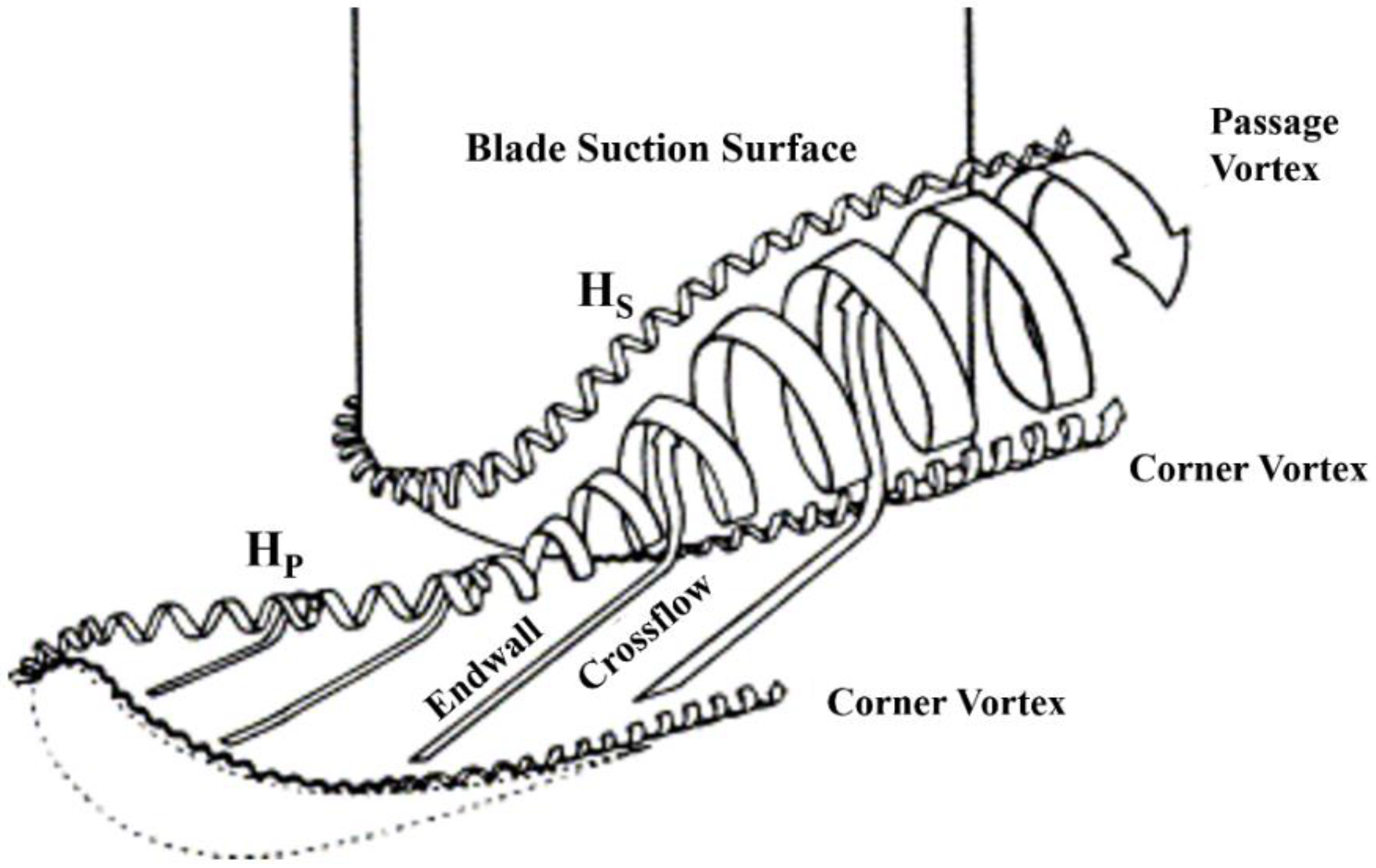
Figure 3.
Different geometric designs of cooling holes.

Figure 4.
Different arrangements of film cooling holes on the endwall [27]. (a) configuration No.1, (b) configuration No.2. Black ellipses indicate hole exit locations on the blade passage side of the endwall; exit angles are indicated too.
Figure 4.
Different arrangements of film cooling holes on the endwall [27]. (a) configuration No.1, (b) configuration No.2. Black ellipses indicate hole exit locations on the blade passage side of the endwall; exit angles are indicated too.
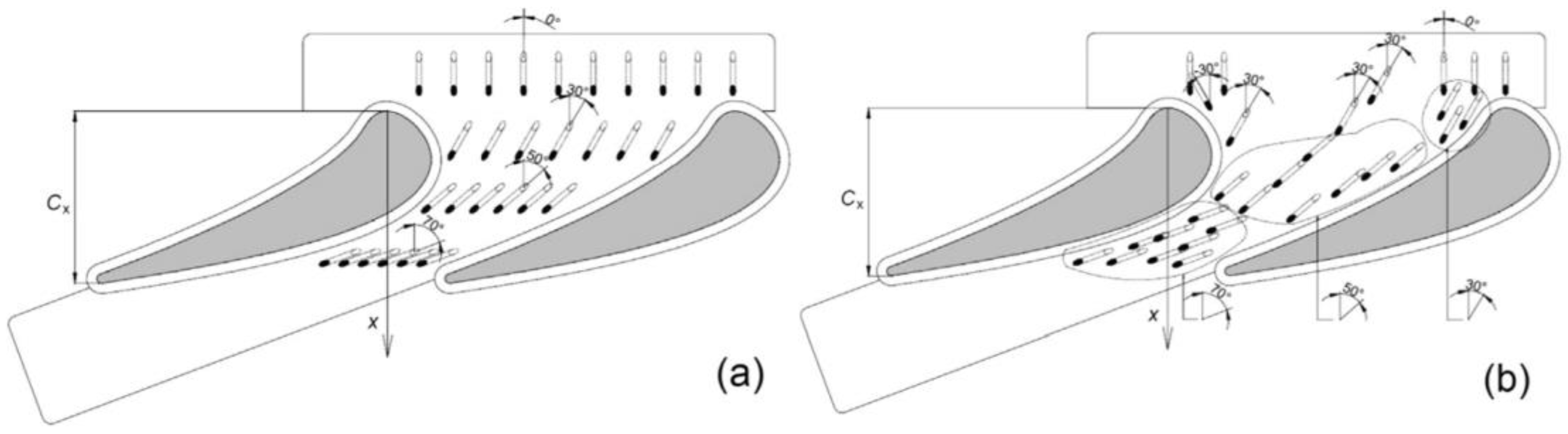
Figure 5.
Investigated upstream slot geometries [44].
Figure 5.
Investigated upstream slot geometries [44].
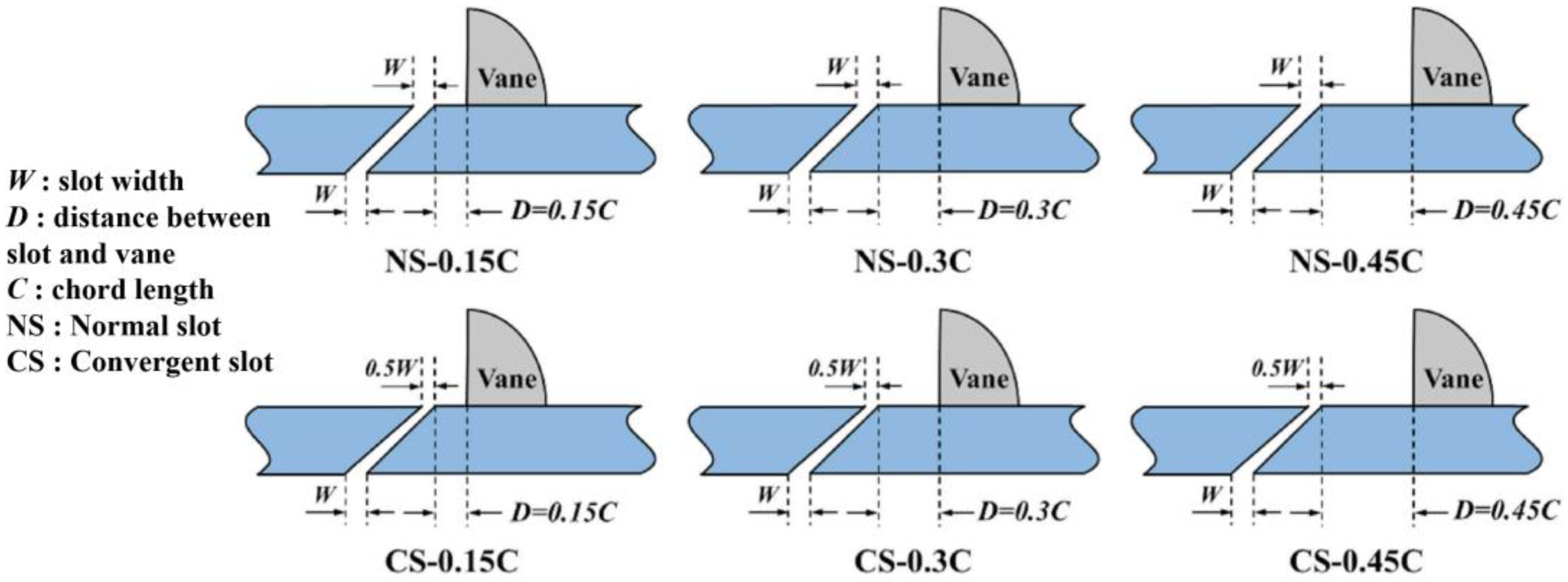
Figure 6.
Comparison of film cooling effectiveness contours [63].
Figure 6.
Comparison of film cooling effectiveness contours [63].
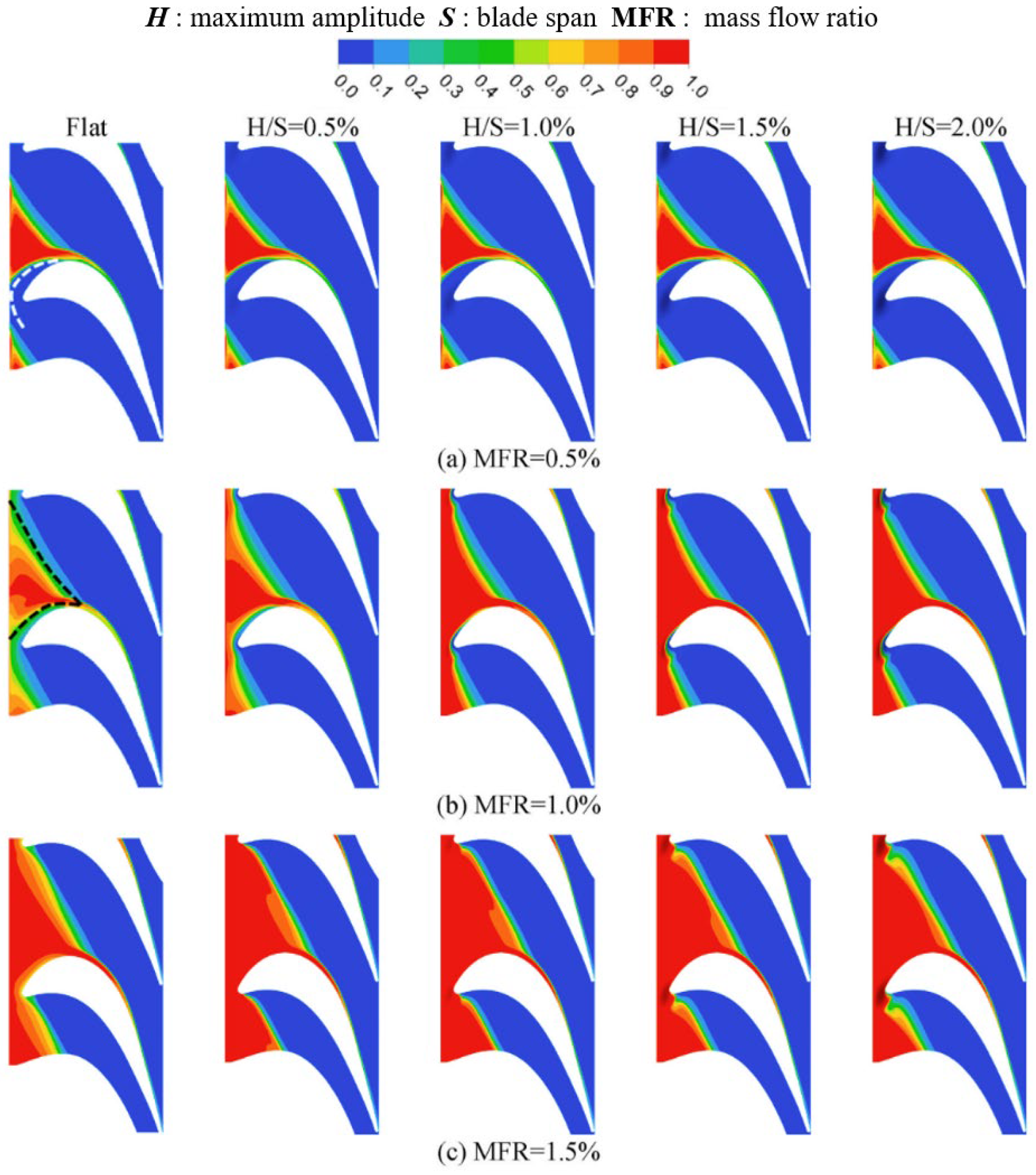
Figure 7.
Definition of the injection angle.
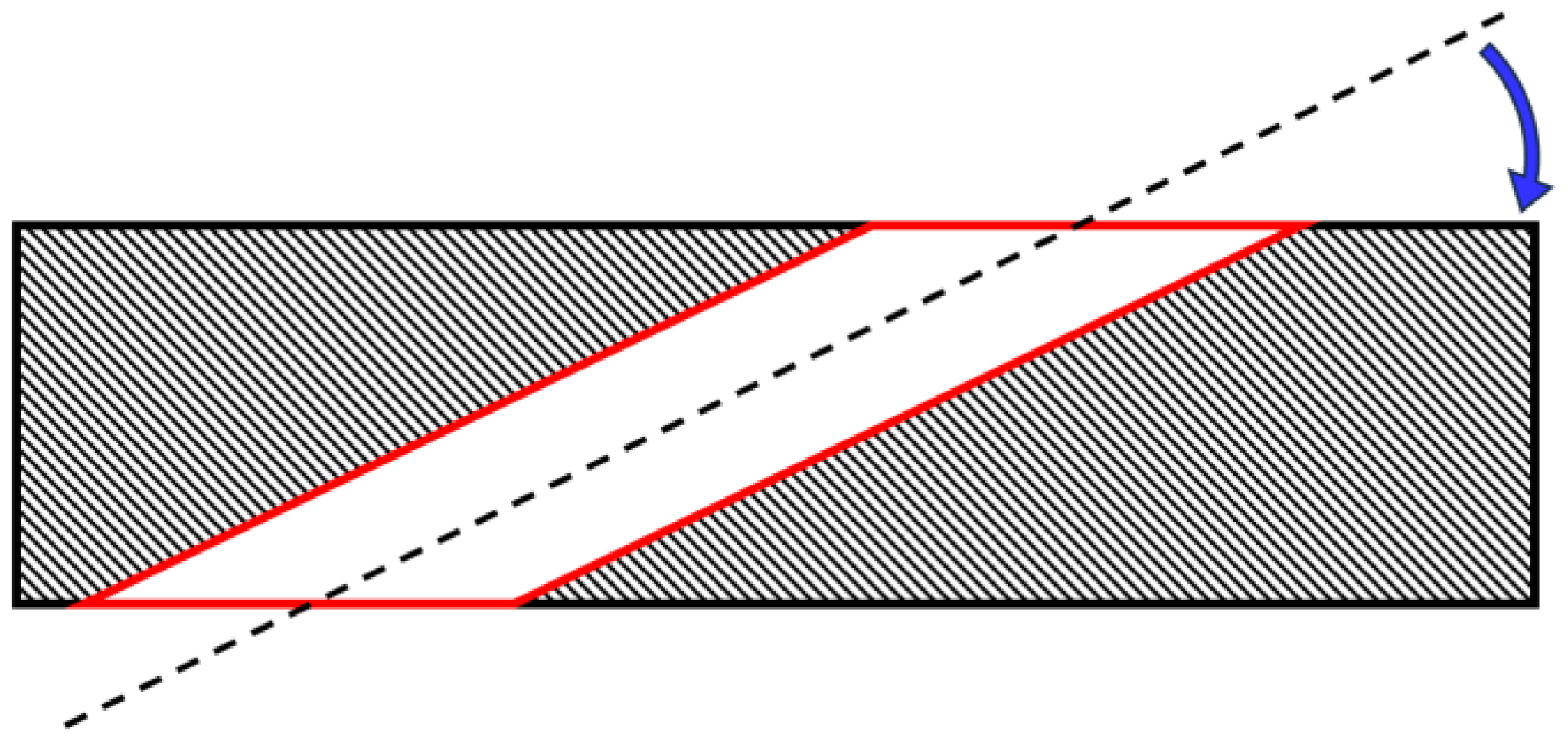
Figure 8.
Instantaneous and time-averaged PIV measurement results at the fixed blowing ratio of M = 1.70 with either air or CO2 as the coolant jet stream [82].
Figure 8.
Instantaneous and time-averaged PIV measurement results at the fixed blowing ratio of M = 1.70 with either air or CO2 as the coolant jet stream [82].
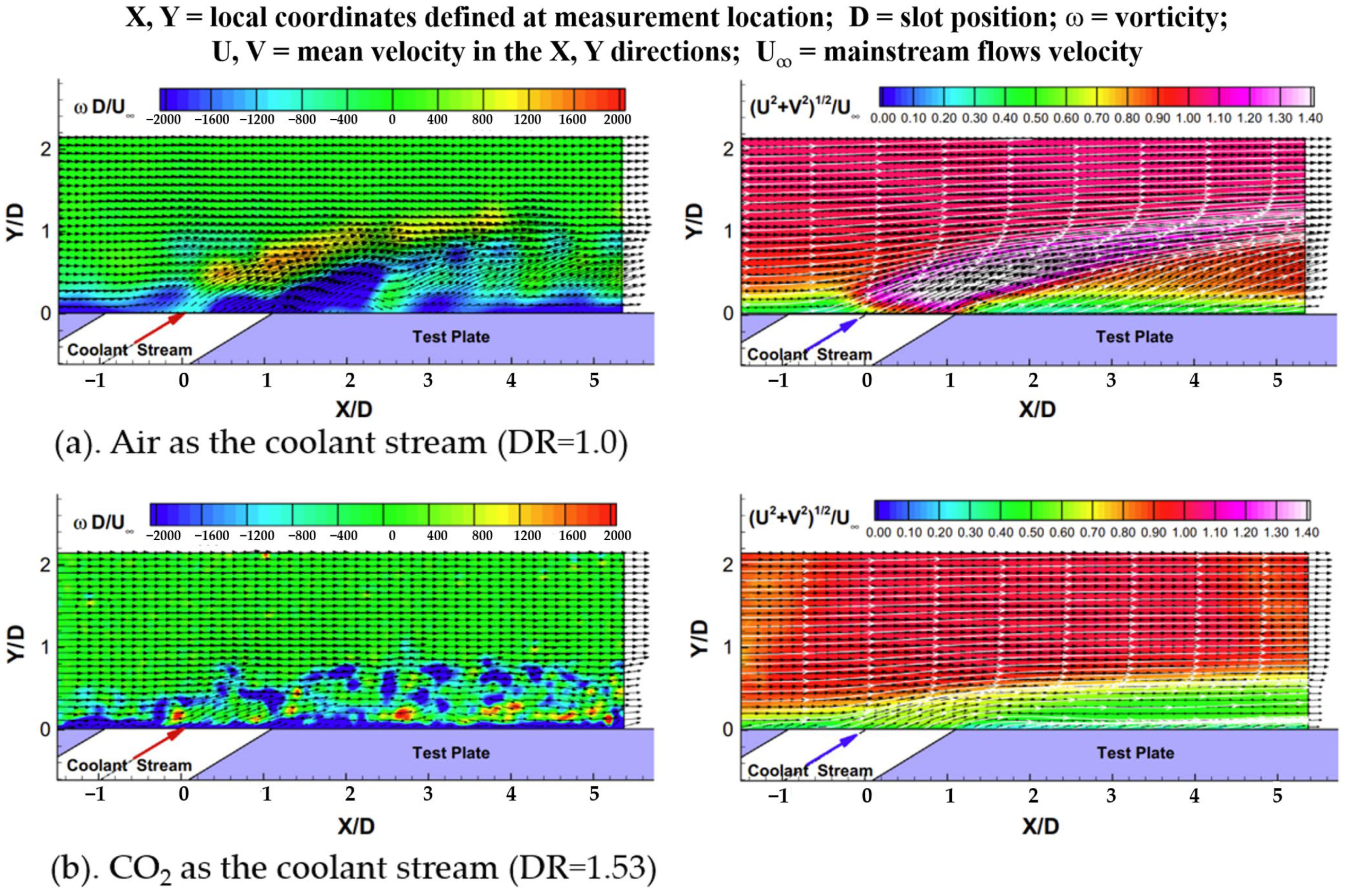
Figure 9.
Surface distribution of adiabatic film cooling effectiveness for different MFRs measured using PSP [83].
Figure 9.
Surface distribution of adiabatic film cooling effectiveness for different MFRs measured using PSP [83].
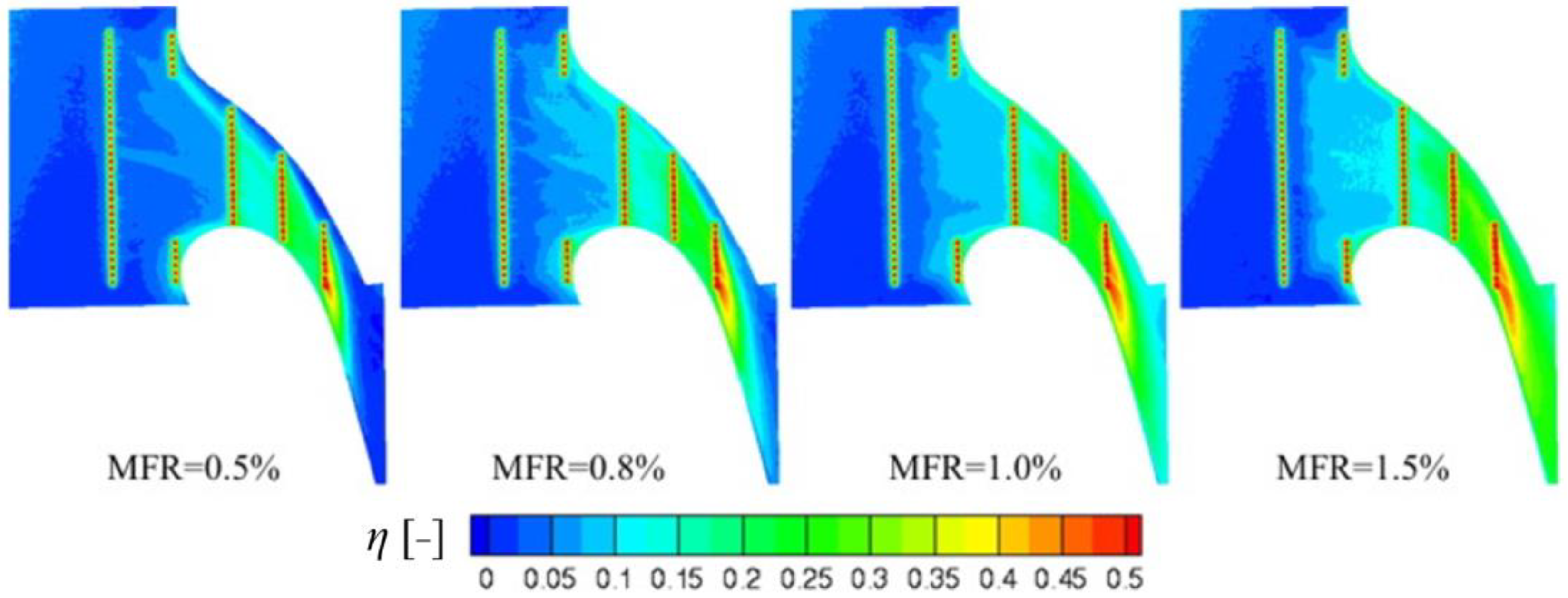
Figure 10.
Contour of the heat transfer coefficients obtained by the steady-state liquid crystal technique [111].
Figure 10.
Contour of the heat transfer coefficients obtained by the steady-state liquid crystal technique [111].


Table 1.
Literature on the study of different boundary conditions.
| Ref. | Numerical Method | Measurement Method | Related Parameter | |
|---|---|---|---|---|
| [69] | Turbulence intensity | / | Laser Doppler velocimeter | Re = 400,000~600,000 |
| [70] | / | Re = 115,000~230,000 | ||
| [71] | / | Steady-state liquid crystal technique | Re = 500,000~2,000,000; T = 37 °C | |
| [72] | / | Naphthalene sublimation technique | Re = 278,000; T = 26 °C | |
| [73] | SST | Hot-wire anemometer | Re = 100,000; T = 25 °C | |
| [74] | k-ε, SST | PSP | Blowing ratio (M) = 0.5~2.0; turbulence intensities (Tu) = 5~25% | |
| [75] | Mass flow ratio | / | PSP, TSP | Mass flow ratios (MFRs) = 0.5~0.8%; T = 313~350 K, density ratio (DR) = 1.1 |
| [76] | / | PSP | MFR = 0.75~1.25%; DR = 1.0~2.0; Ma = 0.7~0.9 | |
| [22] | Blow ratio | k-ε, SST | / | M = 0.6~1.4; T = 328 K; Tu = 3.47% |
| [29] | / | PSP | M = 0.2~1.3; V = 24.3 m/s; T = 276.5 K, 298 K, 308 K | |
| [77] | / | PSP | M = 1.0~2.0 | |
| [78] | RANS, k-ω, SST | / | M = 0.3~0.5; P = 35.6 kPa; T = 350 K | |
| [79] | RANS, k-ω, SST | / | M = 1.3~2.8; P = 179 kPa; T = 295 K; DR = 1.75; Re = 410,000 | |
| [80] | / | PSP | M = 0.5~3; Ma = 0.12 | |
| [81] | / | PSP | M = 0.7~1.3; T = 298~308 K; V = 35 m/s | |
| [12] | Density ratio | RANS | / | DR = 1.2~2.5; Re = 1.7 × 10⁶; Ma = 0.85; M = 2.5 |
| [76] | / | PSP | DR = 1.0~2.0; MFR = 0.75~1.25%; Ma = 0.7~0.9 | |
| [82] | / | PSP, PIV | DR = 0.97~1.53; Re = 2.2 × 10⁵; V = 30 m/s; T = 23~32.6 °C; M = 0.5 | |
| [83] | / | PSP | DR = 1.0~1.51; MFR = 0.5~1.5%; V = 23 m/s; Ma = 0.065; Re = 1.78 × 10⁵ | |
| [32] | Injection Angle | / | PSP | Injection angles = 30~50°; Ma = 0.5; Re = 380,000; DR = 1.5; MFR = 1.0% |
| [84] | Spalart–Allmaras | / | Injection angles = 15°–50°; MFR = 1.3%; | |
| [85] | / | PSP | Injection angles = 30°; Showerhead angles = 30~45°; MFR = 1.5~4% | |
| [86] | Side pressure gradient | LES, k-ω, SST | PSP | M = 1~3; Compound angles = −30~40° |
| [87] | / | PSP | M = 2; Tu = 5% | |
| [88] | Secondary flow | / | PSP | M = 0.8~2.4; Re = 8.6 × 10⁵ |
| [89] | / | Infrared camera system | Re = 6.6 × 10⁵; DR = 1.1; M = 0.05~0.15; MFR = 1.1~13.4% | |
| [90] | / | Thermochromic liquid crystal | Tu = 11%; Re = 3.93 × 10⁵; M = 1.95; MFR = 2%; Ma = 0.19 | |
| [91] | Mach number | RANS, k-ω | / | Ma = 0.012~0.9; Re = 1.2 × 10⁶ |
| [92] | / | Steady-state liquid crystal technique | Ma = 1.0~1.3; Re = 1.0 × 10⁶; Injection angles = 41.54~63.6° |
DR = Density ratio; M = Blowing ratio; Ma = Mach number; MFR = Mass flow ratio.
Disclaimer/Publisher’s Note: The statements, opinions and data contained in all publications are solely those of the individual author(s) and contributor(s) and not of MDPI and/or the editor(s). MDPI and/or the editor(s) disclaim responsibility for any injury to people or property resulting from any ideas, methods, instructions or products referred to in the content. |
© 2023 by the authors. Licensee MDPI, Basel, Switzerland. This article is an open access article distributed under the terms and conditions of the Creative Commons Attribution (CC BY) license (https://creativecommons.org/licenses/by/4.0/).
Share and Cite
MDPI and ACS Style
Zhang, R.; Liu, P.; Zhang, X.; Xi, W.; Liu, J. Recent Developments in the Aerodynamic Heat Transfer and Cooling Technology of Gas Turbines Endwalls. Aerospace 2023, 10, 702. https://doi.org/10.3390/aerospace10080702
AMA Style
Zhang R, Liu P, Zhang X, Xi W, Liu J. Recent Developments in the Aerodynamic Heat Transfer and Cooling Technology of Gas Turbines Endwalls. Aerospace. 2023; 10(8):702. https://doi.org/10.3390/aerospace10080702
Chicago/Turabian StyleZhang, Rongdi, Pengchao Liu, Xirui Zhang, Wenxiong Xi, and Jian Liu. 2023. "Recent Developments in the Aerodynamic Heat Transfer and Cooling Technology of Gas Turbines Endwalls" Aerospace 10, no. 8: 702. https://doi.org/10.3390/aerospace10080702
Note that from the first issue of 2016, this journal uses article numbers instead of page numbers. See further details here.