
Effect of Combustor Outlet Geometry on Operating Characteristics of Disk-Shaped Rotating Detonation Engine


School of Mechanical Engineering, Nanjing University of Science and Technology, Nanjing 210094, China
*
Authors to whom correspondence should be addressed.
Aerospace 2023, 10(8), 732; https://doi.org/10.3390/aerospace10080732
Submission received: 3 July 2023
/
Revised: 12 August 2023
/
Accepted: 14 August 2023
/
Published: 20 August 2023
(This article belongs to the Special Issue Advances in Detonative Propulsion)
Abstract
:A disk-shaped rotating detonation engine with H2/air mixture was tested to identify the impact of combustor outlet geometry on the engine’s operating characteristics. Three combustor outlet diameters and five outlet lengths are employed in the experiments. Results show that with the increase of combustor convergent ratio, the propagation stability of the rotating detonation wave decreases, and the propagation velocity and pressure peak decrease slightly. When the convergent ratio increases to a certain value (1.70 in this study), a “platform zone” with a lower pressure value appears before the sharp rise of the dynamic pressure curve. The propagation mode varies with the increase of mass flow rate at different convergent ratios. As the mass flow rate increases, the wave head number in the combustor increases. But the change rule of propagation mode with mass flow rate is greatly affected by convergent ratio. Increasing the convergent ratio is conducive to the formation of multi-wave modes, and the critical mass flow rate for mode transition drops sharply. When the convergent ratio increases to 1.70, the unstable asymmetric dual-wave mode is obtained. With the increase in the convergent ratio, the engine’s operating range and operating stability decrease significantly. Finally, changing the combustor outlet length has little influence on the engine’s operating characteristics and detonation-wave parameters.
1. Introduction
A Rotating Detonation Engine (RDE) is a new propulsion device based on detonation combustion, which has the advantages of fast energy release rate, high thermal cycle efficiency, self-pressurization, short reaction zone, etc. RDE has the advantages of simple construction, high operating frequency, and wide operation range, so it gets widespread attention recently. Moreover, RDE can be applied to all kinds of propulsive engines including rocket-based mode [1,2], ramjet-based mode [3,4], and RDE turbine combined-cycle engines [5,6]. The operation characteristics of Rotating Detonation Combustors (RDC) with different configurations have been researched [7,8,9].
Researchers have studied the influence of geometric parameters such as different combustor configurations [10,11], diameters, widths, and injection structures [12,13,14] on Rotating Detonation Wave (RDW) propagation characteristics and engine thrust performance [15] in annular RDE and obtained multiple circumferential rotating detonation modes and axial pulse detonation modes [16,17]. It was found that the RDW propagation mode is greatly affected by the injection structure [18]. Compression and expansion of the chamber’s outer and inner walls affect the RDW propagation [19]. With the increase of chamber width, the detonation wave between the two walls inclines. The RDW propagation stability decreases with the increase of the chamber’s outer diameter [20]. Increasing the chamber width, the variation of RDW flow field structure along the radial direction increases [21]. Hansmetzger et al. [7] studied the influence of inner wall geometry on RDW propagation in the annular combustor and found that the velocity and pressure of the detonation wave increased when the length of the center body was shortened or the center half angle was increased. Fan et al. [22] investigated the impact of combustor width on RDW fueled by ethylene and air and found that as the combustor width increased, the RDW propagated more steadily and faster, but the average thrust decreased. Zhu et al. [23] studied the RDW propagation characteristics and performance parameters influenced by nozzle configurations. Results showed that increasing the equivalence ratio or reducing the nozzle throat area were more likely to form unstable propagation modes. Wolański et al. [24] designed a special system of liquid fuel injection, which was based on injecting into the detonation chamber a preheated liquid fuel partially mixed with hot air. Two different liquid fuels, extraction gasoline, and Jet-A fuel were tested in the annular chamber. The research was carried out for different equivalence ratios, and in all tested conditions, detonation was achieved. Zhao et al. [25] investigated the effects of the exit convergent ratio on the RDW initiation processes and obtained that the RDW establishment time increased with the convergent ratio. Deng et al. [26] verified the feasibility of mode control in rotating detonation combustors and further studied the mode transition mechanism under different combustor lengths and outlet blockage ratios.
Tang et al. [27] proposed a hollow RDE without an inner wall and studied the influence of fuel injection area ratio on detonation wave propagation mode and engine propulsion performance [28]. Results showed that with the increase of fuel injection area ratio, the wave head number of detonation wave increased, and the specific impulse increased accordingly. Zhang et al. [29,30] verified the experimental feasibility of hollow RDE by reducing the length of the inner cylinder of the annular RDE and studied the RDW characteristics in the hollow combustor with a Laval nozzle. It was found that the detonation wave number increased with the increase in the nozzle contraction ratio. Liu et al. [31] realized the methane–air rotating detonation in hollow chambers with different diameters and found that the operating range enlarged with the increase of chamber diameter. Reduction in chamber diameter or increase in nozzle contraction ratio would lead to continuous rotating detonation deterioration. Rong et al. [32] studied the complex wave structure in a hollow combustor with a Laval nozzle and found that decreasing the nozzle convergence ratio can significantly weaken the counterrotating shock wave in a combustor and make the RDW propagate more stable. Sun et al. [33] found that a Laval nozzle is beneficial for a hollow RDE to achieve more steady operation and higher thrust output. The height of detonation waves decreases with a larger contraction ratio.
For disk-shaped RDE, Bykovskii [9,34,35,36] and Paxson [37] studied the operation characteristics of disk-shaped RDE under two injection methods that is radially inward flowing and radially outward flowing. Results showed that the inward-flowing RDE outperformed the outward-flowing variant. They also investigated the effect of combustor geometry on the RDW propagation characteristics and found that the wave head number of detonation wave increased with the increase of combustor size. McClearn [38] and Huff [39] et al. studied the influences of the throat area, channel area, and nozzle exit area of the engine on the operating mode and detonation parameters and obtained that decreasing nozzle area ratio was conducive to the formation of multi-wave modes. Watanabe et al. [40] studied the effect of stagnation pressure on RDW propagation patterns at different injection systems and obtained that with the increase of stagnation pressure, both the velocity and pressure increased significantly. Based on the research above, Ishiyama [41] and Huff [42] proposed the concept of a rotating detonation turbine engine, including a centrifugal compressor, a disk-shaped combustor, and a radial flow turbine. Several combustion modes in C2H4/O2 mixture were obtained, and the phenomena of detonation decoupling and re-initiation were observed in the combustor [43]. The RDW propagation processes under different combustor channel heights and injection conditions were also studied and obtained that increasing mass flux produced more power and more efficiency for turbine RDE [42]. Wolański et al. [44] developed disk-shaped detonation chambers working on liquid propellants with regenerative cooling. The specific impulse obtained from the disk-shaped engine was equal to 1600 m/s, about 80% of the theoretical value. For a con-shaped engine with regenerative cooling, the specific impulse increased to 2005 m/s. They also launched the first-in-the-world rocket powered by a disk-shaped detonation liquid rocket engine [45]. The rocket engine worked for 3.2 s, accelerating the rocket to a speed of 93 m/s, which allowed the rocket to reach an altitude of nearly 500 m. It was the world’s first attempt to use a rotating detonation engine powered by liquid propellants to propel a rocket.
In view of the special disk-shaped combustor, it is conducive to capturing the full wave system and flame development by visualization [46,47]. Furthermore, studies have shown that the disk-shaped RDE has good matching with centrifugal compressors and radial flow turbines [41,42,43], which has wide application prospects. Based on the analysis above, the research on the combustor configuration and geometric parameters is mainly focused on the annular RDE. There is research on the influence of the geometric parameters of disk-shaped combustors on RDW propagation characteristics. It is essential to study the RDE operation characteristics and its influencing factors in this configuration. Based on this, the primary aim of the current work is to study the influence of combustor outlet configuration on the operating characteristics of disk-shaped RDE. Employing high-frequency pressure and ion measurement methods by changing the combustor outlet diameter and length, the influence rules of combustor outlet geometry on the RDW propagation stability, propagation mode, detonation-wave parameter, and RDE operating range are studied in depth. Basic research of the RDW propagation in the disk-shaped RDE is not only essential to enrich the detonation physical mechanism but also for engineering applications of detonation propulsion.
2. Materials and Methods
The disk-shaped RDE experimental system includes a reactant supply system (2–8, 13, 15), disk-shaped RDEs (1), ignition system (9, 13, 15), measurement, and data acquisition system (10–12, 14, 16), as shown in Figure 1, Figure 2 and Figure 3 represent the air and H2 tanks, which are used to provide the oxidizer and fuel required for detonation. The reducing valve (4) and sonic nozzle (5) are used to control the flow rate of supply pipelines. During the test, the sonic nozzle reaches choking state. By regulating the exit pressure of the upstream reducing valves (4), the supply mass flow rates of fuel and oxidizer are adjusted in the tests. The mass flow rates of fuel and oxidizer are regulated using the flow choking formula for calculation. The uncertainties associated with mass flow rate and equivalence ratio are analyzed through linearized systematic error. The uncertainty in pressure and temperature upstream of the sonic nozzles is ±0.30 bar and ±5.0 K, respectively. For the case with air and hydrogen mass flow rates of 206 g/s and 9.5 g/s (equivalence ratio of 1.58, which will be employed in the following section), the uncertainties in air and hydrogen mass flow rates are ±5.32 g/s and ±0.31 g/s, respectively. This results in an error of ±0.066 in the equivalence ratio. The ball valve (6) is used to manually control the interruption of the supply pipeline. The electromagnetic valve (7) can achieve the on–off control of the supply pipeline through timing control, with a response time on the order of milliseconds. This ensures that the time error of the experimental sequence remains within an acceptable range. The flashback arrester (8) is installed on the fuel supply pipeline to prevent flame from returning and safety accidents. The disk-shaped RDE is ignited by spark plug (9). Ten, eleven, and twelve represent sensors. The ion probe (10) is used to measure the flame front signal in the combustor. The piezoelectric sensor (11) is used to measure the dynamic pressure signal of detonation waves. The piezoresistive sensors (12) are used to measure the average pressure in the combustor and the injection pressures in the air and H2 plenums. In brief, 13 and 14 represent the control system and data-acquisition system, respectively, and 15 and 16 are the computers for control and acquisition in the tests.
In this study, the disk-shaped structure is employed, and the engine schematic is shown in Figure 2. Different from the annular RDE, the disk-shaped combustor has a special structure. H2 and air are supplied from ports 1 and 5 into the plenums. The reactants are injected into the combustor radially inward from the annulus with a diameter of 120 mm (d1), and the injection surface (3) is shown in Figure 2. Using a non-premixed injection method, air as oxidizer is injected into the combustor through Laval-nozzle slit, whereas H2 as fuel is injected through 120 uniformly distributed orifices (not shown in Figure 2). The walls on both sides and the injection annulus form a rotating detonation combustion channel (7). The reactants are initiated by a low-energy spark plug (6), and one or more rotating detonation waves are rapidly formed in the combustor. The detonation wave rotates and propagates in the circumferential direction, and the combustion products expand in the radial direction, converge in the center, and discharge axially from outlet (11), as shown in Figure 2.
Three combustor outlet diameters (d2) are selected in this experiment, which is marked as engine M1, M2, and M3, respectively. In Figure 2a, l is the length of outlet straight section. Five groups of outlet length are selected for study. The impact of outlet length on RDW propagation characteristics is studied by replacing the outlet straight section of engine M2, which is marked as engine M2_1~M2_5. Table 1 lists the geometric parameters of combustor with different outlet diameters and lengths. The channel convergent ratio (CR) is defined as , where SInlet is the inlet area of the combustor, and Smin is the minimum channel area. The combustion products exhaust into the atmosphere directly, and the environmental pressure and temperature are 1.0 bar and 285 K, respectively.
The dynamic high-frequency pressure sensors are installed on the right side of combustor, as shown in Figure 2b. Two piezoelectric sensors (PCB113B24, 10, p1, p2) are arranged to capture the dynamic pressure signals in combustor, and circumferentially separated by 90°. The resonant frequency of the PCB pressure sensor is great than 500 kHz, and the rise time is less than 1.0 μs, with the measurement range of 6, 895 kPa. An ion probe (8, I1) is installed on the left side to monitor the flame signal in the combustor, with the same position as the dynamic pressure sensor (p1).
The operation principle of the ion probe is to detect the propagating reaction front, combustion mode, propagation velocity of the reaction front, and flame surface thickness by measuring the ion current in the reactive medium [48]. The ion probe used in this paper is designed by our own research team. A host of detonation tube ignition tests are carried out to test the rise time of the ion probe, and the rise time is obtained at less than 10 μs, which is sufficient to capture the RDW flame front. Figure 2c shows the schematic diagram of ion probe measurement system.
Three piezoresistive sensors (9) are employed to measure the average pressures in the reactant plenums and combustor. The accuracy grade of the piezoresistive sensors is 1%FS, and the response time is less than 1 ms. The above-mentioned sensors have been employed in previous research [26,49], which are sufficient to satisfy the RDE experimental requirements.
NI X series multifunction DAQ with data-acquisition card (USB-6366) is used to acquire the sensor signals. The maximum sampling frequency is 2 M/s per channel, and the input resolution is 16 bits. All instrumentations are sampled at an acquisition rate of 500 kHz in this study. Other details of the experimental system have been described in Ref. [50].
3. Results
In this paper, the disk-shaped rotating detonation combustor is used as the test object to study the influence of combustor outlet geometry on the RDW propagating characteristics. First of all, the operating process of the disk-shaped RDE is analyzed briefly [49].
The disk-shaped RDE adopts a separate injection method. The electromagnetic valves in the fuel and oxidizer supply pipelines open simultaneously, and H2 and air are injected through orifices and slots into the combustor, respectively. After 1 s of reactants supply, the ignition system is triggered. The spark plug discharges and ignites the reactants in the combustor. The flame develops and accelerates rapidly and undergoes the deflagration to detonation transition (DDT), and finally forms a stable and continuous propagating rotating detonation wave. The detailed studies on the RDW initiation process are shown in Ref. [51]. By capturing the dynamic pressure signals in the combustor and average pressures in the combustor and plenums, the RDW propagating mode and propagating stability are judged. After the engine operates for about 0.2 s, the electromagnetic valves shut off to stop the reactants supply. The remaining gases in the pipeline maintain the RDW propagating for a period of time. Finally, the engine shuts down due to the lack of reactants. The detailed studies on the RDW propagation mode and propagation stability are shown in Refs. [49,52].
In this study, by changing the combustor geometry, the effects of outlet diameter and outlet length on the RDW propagating process and operating mode are studied. Three kinds of combustor outlet diameters are selected, which are 56, 50, and 46 mm, respectively. Five kinds of combustor outlet lengths are selected, which are 20, 30, 46, 60, and 80 mm for experimental research. The detailed geometry sizes of the combustors are listed in Table 1. The typical experimental conditions are shown in Table 2, where the abbreviations of SW and SDW stand for Single-wave mode and Symmetric Dual-wave mode, respectively.
3.1. Effect of Convergent Ratio on RDW Propagating Process and Parameters
Table 1 lists the geometry parameters of the combustors with different outlet diameters. As shown, the outlet diameter decreases from 56 mm to 50 mm and finally to 46 mm, and the channel convergent ratio increases from 1.08 to 1.36 and then to 1.7. Taking operating conditions #1, #2, and #3 as examples, the influences of convergent ratio on the RDW propagating process and detonation-wave parameters are analyzed in detail. The injection conditions of the above three operating conditions are basically the same, only changing the channel convergent ratio. Figure 3, Figure 4 and Figure 5 show the dynamic pressure traces, Fast Fourier Transform results, and ion signals captured in the combustor at the above three operating conditions, respectively.
As shown in Figure 3, at the conditions of three convergent ratios, the RDE always operates in a single-wave mode. Figure 3a,c,e show the dynamic pressure traces captured in the RDC with different convergent ratios, where p1 and p2 are the dynamic pressure curves acquired at diameters 102 mm and 82 mm, respectively. As shown, when the convergent ratio is 1.08 or 1.36, the dynamic pressure traces fluctuate steadily. The pressure peaks in the stable operating stage fluctuate slightly over time, and the peak of the p2 curve is slightly less than that of p1. From the partially enlarged views, the dynamic pressure curve shows the fluctuation characteristics of “sharp rise and falling slowly” in one propagating period, which fits the characteristics of a typical detonation-wave pressure curve, as shown in Figure 3a,c.
Figure 3e shows the dynamic pressure traces in the combustor with a convergent ratio of 1.70. As shown, the dynamic pressure traces show unstable oscillation characteristics. The pressure peak changes periodically, accompanied by low-frequency instability. From the partially enlarged view in Figure 3e, the waveform of the dynamic pressure curve also shows a characteristic of “sharp rise and falling slowly”. But there is a “platform zone” with low peaks before the sharp rise of the pressure curve, as shown by the arrows in Figure 3e, which indicates that a weak shock wave passes through the PCB sensors before the incoming detonation wave.
In addition, this “platform zone” is only observed in the RDC with the convergent ratio of 1.70. From published literature, Deng et al. [53] also found this “platform” in the annular RDC and found that the platform would vanish with the increase of air mass flux. They thought that there were two key factors causing the platform. One reason was the average pressure in the chamber was lower than the backpressure, and then a shock wave was generated to balance the pressure between both. Another reason was that the secondary reaction caused by remnant mixtures intensified the shock and pushed its propagation back to the chamber. But in this study, the injection conditions of cases #1–#3 are consistent. The inducement of the platform zone is no longer the mass flow rate, but the increase in the channel convergence ratio of the RDC. For a combustor with a larger convergent ratio, the oblique shock wave induced by the rotating detonation wave reflects and forms a shock wave in the outlet convergent section. The reflected shock wave passes back to the combustor, sweeping through the dynamic pressure sensors, and generates a platform zone ahead of the detonation wave.
Figure 3b,d,f shows the Fast Fourier Transform results of dynamic pressure, p1, in cases #1, #2, and #3, respectively. As shown, under the aforementioned operating conditions, RDWs propagate in a single-wave mode, and spectral analysis reveals clear dominant frequencies, which correspond to the propagation dominant frequencies of RDWs. Specifically, in cases #1, #2, and #3, the propagation dominant frequencies of RDWs are 5.84 kHz, 5.78 kHz, and 5.62 kHz, respectively. As the channel convergence ratio increases, the propagation frequency of RDWs gradually decreases.
Overall, in the RDC with a small convergent ratio, RDW propagates steadily, and the detonation-wave pressure peak fluctuates slightly. However, at the same injection condition, increasing the channel convergent ratio, the RDE operating stability decreases, and the RDW propagation frequency decreases correspondingly. The fluctuation amplitude of the pressure peak increases correspondingly, and a platform structure with lower pressure appears in front of the detonation wave.
Figure 4 shows the comparison of the dynamic pressure signal and ion signal in the combustor in case #2. From Section 2, the PCB pressure sensor (p1) and the ion probe (I1) are installed at the same position, but on both sides. From Figure 4, the rising edges of the dynamic pressure signal and the ion signal are basically consistent, as well as the oscillation frequency. It is indicated that the shock wave front is well coupled with the flame front, which is in line with the characteristics of detonation waves. In the disk-shaped RDC, the rotating detonation wave is indeed initiated and propagates continuously.
From Figure 3e, when the channel convergent ratio increases to 1.70, in addition to the high-frequency pressure oscillations caused by RDW propagation, the pressure peak also shows a periodic oscillation, with an oscillation frequency of approximately 436 Hz. In case #3, the RDW propagation frequency is approximately 5.62 kHz. Compared with the RDW frequency, the periodic oscillation frequency of the pressure peak is reduced by one order of magnitude, which is called a low-frequency oscillation phenomenon.
Figure 5 shows the ion signal curve in the combustor at case #3. According to the partially enlarged image of the ion signal curve shown in Figure 5b, it can be observed that under the operating condition of case #3, the ion voltage signal exhibits periodic oscillations over time. However, the oscillation process is highly unstable, with significant fluctuations in the amplitude over time. In some periods, the troughs of the ion signal do not return to zero, as indicated by arrow (1) in Figure 5b. This may be attributed to the delayed expulsion of high-temperature detonation combustion products, leading to intensified deflagration at the contact surface, and thereby raising the ion concentration at the monitoring point. Furthermore, there are even interruptions in certain regions of the ion curve, as indicated by arrow (2) in Figure 5b. This indicates an unstable propagation process of RDWs under this operating condition. During some propagation cycles, the combustion reaction induced by the detonation wave is relatively weak. Moreover, further Fast Fourier Transform (FFT) is conducted on the ion signal, revealing a dominant frequency of 5.62 kHz, which is consistent with the dominant frequency of the dynamic pressure signal shown in Figure 3e.
Additionally, based on Figure 5a, the low-frequency oscillation phenomenon is also observed in the ion signal, that is, the amplitude of ion voltage varies periodically with time. This indicates that at this condition, the RDW propagation process is unstable, and the intensity of the detonation wave varies periodically in strong and weakness over time. Further research on the propagation characteristics of this low-frequency instability is presented in Ref. [54]. In this study, it is found that increasing the channel convergent ratio will reduce the RDW propagation stability and promote the formation of low-frequency oscillation instability.
In addition, from Figure 3 and Figure 5, the detonation-wave parameters are also greatly affected by the combustor convergent ratio, including pressure peak and propagation velocity. The detonation-wave pressure peak and propagation velocity at a diameter of 102 mm are shown in Figure 6. With the increase of convergent ratio, both the detonation-wave pressure peak and velocity decrease, and the decline rate gradually increases. Additionally, the standard deviation of detonation-wave parameters increases significantly with the increase of the convergent ratio, indicating that the RDW propagation stability decreases with the increase of the convergent ratio. Here are the reasons: On the one hand, as the convergent ratio increases, the average pressure in the combustor increases, which is conducive to the organization of detonation combustion and enhances the velocity and pressure of the detonation wave. On the other hand, an increase in the convergent ratio will hinder the discharge of high-pressure detonation products. The prolonged residence time of high-temperature products in the combustion chamber intensifies the deflagration process on the contact surface, resulting in a decrease in detonation combustion efficiency. Additionally, the excessively high chamber pressure obstructs the injection process of fresh reactants, leading to a lower reactant layer ahead of the detonation wave. As a result, the intensity of the detonation wave is significantly reduced due to the influence of lateral expansion waves, and the propagation process becomes more unstable. Considering the combustor outlet geometry used in our study, the negative impacts of increasing the convergence ratio outweigh the positive effects. Consequently, the velocity and pressure of the detonation wave decrease while the convergence ratio increases, with an increasing rate of decline.
Figure 7 shows the influences of combustor convergent ratio and equivalence ratio on detonation-wave propagation velocity. From Figure 7, the variation tendency of RDW propagation velocity on reactants equivalence ratio is consistent in the combustors with different convergent ratios, which shows that the propagation velocity gradually increases with the increase of equivalence ratio. In addition, from Figure 7, at the identic injection condition and propagation mode, the convergent ratio of the combustor has a small impact on the RDW propagation velocity. In the combustor with a small channel convergent ratio, the propagation velocity is slightly higher.
In summary, within the scope of operating conditions studied in this paper, increasing the convergent ratio of the disk-shaped RDC, the RDE stable operation range is reduced significantly. and the RDW propagation stability is also reduced. However, it has little impact on the detonation-wave parameters, and increasing the convergent ratio will slightly reduce the RDW propagation velocity and pressure peak. The reasons for the above changes have been explained, which is that increasing the convergent ratio will hinder the discharge of high-pressure detonation products. Fresh reactants cannot be injected timely. As a result, the reactants mixing efficiency and reactants layer height decrease, leading to the RDW propagation instability.
Furthermore, the error bars in Figure 7 show the standard deviations of the RDW propagation velocity, in order to characterize the dispersion degree of detonation-wave parameters in each condition. As shown, under one combustor structure, as the equivalence ratio increases, the standard deviation is roughly decreased. The standard deviation of symmetric dual-wave mode is lower than that of single-wave mode, but the standard deviation of asymmetric dual-wave mode is higher. At the same injecting conditions, the standard deviation of detonation-wave parameters decreases with the decrease of the combustor convergent ratio. In conclusion, by increasing the reactants equivalence ratio or decreasing the combustor convergent ratio, the standard deviation of RDW parameters decreases, indicating that the RDW propagation stability is improved. In addition, the propagation stability of stable multi-wave mode is higher than that of single-wave mode.
3.2. Effect of Convergent Ratio on RDW Propagation at Higher Mass Flow Rates
Changing reactants’ mass flow rates, it is obtained that at higher mass flow rates, the combustor convergent ratio will affect the RDW propagation mode. Taking cases #4, #5, and #6 as examples, the impact of convergent ratio on wave head number in the combustor is analyzed. The captured dynamic pressure curves are shown in Figure 8.
As shown in Figure 8, in case #4, RDW propagates steadily in a single-wave mode in the RDC with a convergent ratio of 1.08. The detonation-wave pressure peak and velocity fluctuate slightly with time. When the convergent ratio increases to 1.36, the RDW propagating mode in the RDC is still single-wave mode, as shown in Figure 8b. But, in each period, the secondary peak appears after the main peak of the dynamic pressure curves, which is consistent with the curves in Figure 3c. When the convergent ratio increases to 1.70, the RDW propagation mode is transformed into a stable co-rotating dual-wave mode at the same injection condition, as shown in Figure 8c. Compared with the single-wave mode under the same injection condition, the detonation-wave pressure peak in the dual-wave mode is significantly reduced. A secondary peak also appears behind the main peak of the pressure curve. To sum up, under the condition of a higher mass flow rate, increasing the convergent ratio can increase the number of wave heads in the combustor.
In addition, compared to the injection conditions of case #3, the mass flow rate of case #6 is larger and the equivalence ratio is closer to the stoichiometric ratio. The reactant height, mixing efficiency, and chemical reactivity of the reactants at case #6 increase, making it easier to promote the formation of dual-wave mode.
Figure 9 shows the mean values and standard deviations of the detonation-wave velocity and pressure peak at a diameter of 102 mm at 282 g/s. Similar to Figure 6, with the increase of convergent ratio, the mean values of the detonation-wave parameters decrease, and the standard deviations increase slightly. In addition, zone (1) in Figure 9 shows the detonation-wave parameters of the dual-wave mode. Compared with the single-wave mode, the detonation-wave propagation velocity and pressure peak are significantly reduced, but the standard deviation is also reduced. It is indicated that in the dual-wave mode, the intensity of a single detonation wave is significantly reduced, but the propagation stability is improved.
3.3. Effect of Convergent Ratio on RDE Operation Mode
This section mainly studies the impact of the combustor convergent ratio on the RDE operation mode. The reactants equivalence ratio is about 1.10. Figure 10 shows the variation of RDE operation mode and RDW propagation frequency with a mass flow rate in three combustors with different convergent ratios.
As shown in Figure 10, with the increase in mass flow rate, the operation mode of RDE with different convergent ratios varies. In the combustors with convergent ratios of 1.08 and 1.36, the changing rules of RDE operating mode with mass flow rate are consistent. Specifically, with the increase of mass flow rate, the operating mode is transformed from unstable propagation mode to stable single-wave mode and then transformed into symmetric dual-wave mode. A low-frequency instability (LFI) is obtained near the critical condition of modes switching, as shown in Figure 10a,b. As for the combustor with a convergent ratio of 1.70, with the increase of mass flow rate, the RDE operating mode changes from single-wave mode to unstable asymmetric dual-wave mode, and RDE operates in an unstable hybrid mode of asymmetric dual-wave mode and symmetric dual-wave mode (ADW/SDW hybrid mode) at some conditions. When the mass flow rate continues to increase, the RDE operation mode is transformed into symmetric dual-wave mode, as shown in Figure 10c. Moreover, when the mass flow rate is greater than 400 g/s, the RDE operation process tends to be unstable, and the standard deviation of RDW frequency increases significantly.
In addition, the critical mass flow rate of mode transformation varies with the combustor convergent ratio. When the convergent ratio increases from 1.08 to 1.36, the critical mass flow rate for the transition from SW mode to SDW mode decreases slightly, from 338 g/s to 323 g/s. But when the convergent ratio increases to 1.70, the critical mass flow rates for mode transformation are significantly reduced. The critical mass flow rate for the transformation from SW mode to ADW mode is 104 g/s, and the critical mass flow rate for the transformation from ADW mode to SDW mode is 270 g/s. Furthermore, when the convergent ratio increases to 1.70, the asymmetric dual-wave mode is obtained in the combustor, which indicates that increasing the channel convergent ratio promotes the formation of an unstable multi-wave mode.
According to the standard deviations shown in Figure 10a–c, when the convergent ratio is 1.08 or 1.36, the standard deviation of RDW frequency is relatively small, and the frequency fluctuation amplitude is less than 7.5%, including the unstable propagation mode. The frequency fluctuation amplitude in the stable propagation mode is mostly less than 2%. These indicate that the RDW propagation process is stable. When the convergent ratio increases to 1.70, the standard deviation of frequency increases significantly. For the stable propagation mode, the frequency fluctuation amplitude ranges from 1.5% to 10.8%. While for the unstable ADW mode, the frequency fluctuation amplitude is about 20%. It is further proved that the RDW propagation stability will be greatly reduced when the channel convergent ratio increases to a certain value (1.70 in this study). Moreover, Figure 10d compares the RDW frequencies in the combustor with different convergent ratios. It is obtained that at the same injecting conditions, the RDW propagation frequency is almost independent of the combustor convergent ratio.
In conclusion, with the increase of combustor convergent ratio, the critical mass flow rate of mode transformation decreases, which is conducive to the formation of multi-wave modes in the RDC. When the convergent ratio increases to a certain value, an unstable asymmetric dual-wave mode is obtained in the combustor. This is because with the increase of the combustor convergent ratio, the high-temperature detonative products are not easy to discharge, and the residence time in the combustor increases, leading to the enhancement of the deflagration intensity on the contact surface. The above process is conducive to the generation of local hot spots. In addition, the combustor convergent ratio increases, which is equivalent to installing a convergent nozzle at the outlet, and the oblique shock wave derived from RDW will reflect on the outlet convergent surface. The reflected shock wave propagates upstream to the reactants layer and then induces local hot spots. Therefore, increasing the convergent ratio is conducive to the generation of multi-wave operation modes in the combustor.
However, if the combustor convergent ratio is too large, the residence time of detonative products in the combustor is too long, which will seriously affect the injection process and injection stability of fresh reactants. The reactant height ahead of the detonation wave is unstable, which in turn leads to the decline of the RDW propagation stability. There will even be a periodic increase and decrease in detonation strength, that is, obtaining unstable asymmetric dual-wave mode [52]. Therefore, when the combustor convergent ratio increases to 1.70 in this study, the RDW propagation stability is dropped sharply, and an unstable ADW mode is obtained.
3.4. Effect of Convergent Ratio on RDE Operation Range
The influence of the combustor convergent ratio on the RDE operation range is further studied. Figure 11 shows the RDE operation mode and the scope of equivalence ratio for RDW propagation at different convergent ratios. Where F represents the operating conditions of failure initiation, that is, the combustion process was not successfully established in the disk-shaped combustor. The air mass flow rates at the experimental conditions used in this section are consistent, about 206 g/s.
As shown in Figure 11, at the condition of air mass flow rate of 206 g/s, in the combustor with the convergent ratio of 1.08 or 1.36, the RDE always operates in the single-wave mode within the detonable scope of equivalence ratio. However, in the combustor with the convergent ratio of 1.70, with the increase of equivalence ratio, the RDE operating mode changes from SW mode to ADW mode, and then is transformed into SDW mode. As the equivalence ratio continues to increase, the RDE operating mode is converted to ADW mode again, and eventually transformed into SW mode, which further proves that increasing the combustor convergent ratio is conducive to the formation of multi-wave mode.
From the error bars of the frequency shown in Figure 11, when the RDE operates in a SW mode, the standard deviation of frequency is small, indicating that the RDW propagation process is relatively stable. But in the combustor with a convergent ratio of 1.70, an unstable ADW mode is obtained, and the error bar increases significantly. It is further proved that the RDW propagation stability will be reduced significantly if the combustor convergent ratio is too large.
Moreover, from Figure 11, the RDE operation range also changes significantly with the variation of the combustor convergent ratio. In this study, when the convergent ratio is 1.08, the engine has the widest operating range of equivalence ratio, about from 0.52 to 1.95. With the increase of convergent ratio, the lower limit of engine operation increases slightly, but the upper limit decreases significantly. In this study, when the convergent ratio is 1.36 or 1.70, the lower limit of the RDE operating equivalence ratio is 0.80 and 0.73, respectively, and the upper limit is about 1.60. Compared with the combustor with the convergent ratio of 1.08, the RDE operating range is significantly reduced. But there is little difference in the operating range of engines with convergent ratios of 1.36 and 1.70. In conclusion, for the disk-shaped RDE studied in this paper, increasing the combustor convergent ratio is conducive to the formation of multi-wave modes, but the stable operating range of the engine is reduced, and the corresponding operating stability is also reduced.
3.5. Effect of Outlet Length on RDW Propagating Characteristic
In this section, the influences of different combustor outlet lengths on the RDW propagation process and detonation-wave parameters are studied by replacing the outlet straight section of engine M2 (CR = 1.36). Typical test conditions are listed in Table 2. Cases #7–#11 are selected for research. Five lengths of straight section outlets are used for experimental research, namely 20, 30, 46, 60, and 80 mm. At the same injecting condition (mass flow rate of 139.6 m/s, equivalence ratio of 1.18), the dynamic pressure curves in the combustor with different outlet lengths are obtained, as shown in Figure 12.
In addition, a secondary peak is discovered after the main wave peak caused by the detonation wave, and the second peak value is about half of the main peak. This is mainly due to the included angle between the detonation wave and the normal direction of the injecting surface. The reflected shock wave formed by the reflection of detonation wave on the injecting surface, which is consistent with the previous numerical simulation results [55].
In order to study the influence of combustor outlet length on RDW parameters, Figure 13 shows the influence of outlet length on RDW propagation velocity and pressure peak at different air mass flow rates. The data in the figure are the mean values and standard deviations of detonation-wave parameters at a diameter of 102 mm. Four groups of air mass flow rates (140 g/s, 206 g/s, 300 g/s, and 353 g/s, respectively) are selected for experiments, and the reactant equivalence ratio is about 1.2.
From Figure 13, at the same injecting condition, the RDW propagation velocity and pressure peak vary slightly with the change of combustor outlet length, and the RDW propagation mode has not changed. However, the RDW propagation velocity and pressure peak are greatly affected by mass flow rate. The variation trend of detonation-wave parameters with mass flow rate is consistent under different outlet lengths. As shown in Figure 13a, with the increase of mass flow rate, the RDW propagation velocity increases linearly, but when the mass flow rate increases to 353 g/s, the average velocity decreases significantly. This is because, at this mass flow rate, the RDW propagation mode is transformed from SW mode to SDW mode. The detonation-wave strength and parameters in SDW mode are lower than those in SW mode. Figure 13b shows the variation of RDW pressure peak with mass flow rate. Similar to the velocity, the pressure peak increases with the increase of mass flow rate. When the mass flow rate increases to 353 g/s, the RDW pressure peak in SDW mode is significantly lower than that in SW mode.
Furthermore, the standard deviations of detonation-wave parameters at different operating conditions are counted, as shown in the error bars in Figure 13. At the same injection condition, the standard deviations have little difference in the combustor with different outlet lengths, indicating that the outlet length has little influence on the fluctuation of detonation-wave parameters. With the increase of mass flow rate, the standard deviations of detonation-wave parameters increase gradually. The standard deviation in the SDW mode is lower than that in the SW mode. In addition, it is found that the standard deviations increase significantly at the mass flow rate of 300 g/s. This is because an unstable low-frequency oscillation phenomenon is observed at this operating condition, and the detonation-wave pressure peak performs a periodic sine oscillation over time [52]. This low-frequency instability leads to a significant increase in fluctuations of detonation-wave parameters, especially pressure peak. The above propagation characteristics are almost not affected by the combustor outlet length.
In conclusion, changing the combustor outlet length has little influence on the RDW propagation process, operation mode, and detonation-wave parameters.
4. Conclusions
In this paper, a series of experiments is performed to study the propagating characteristics of H2/air rotating detonation wave in different combustor outlet geometries in a disk-shaped rotating detonation engine. By changing the outlet diameter, outlet length, injecting mass flow rate of reactants, and equivalence ratio, the influence of engine configuration on the RDW propagation process, detonation-wave parameters, RDE operation mode, and operating range are studied. The results are as follows:
(1) At the same injecting condition, with the increase of combustor convergent ratio, the RDW propagation stability decreases, and the fluctuation amplitude of the detonation-wave pressure peak increases. When the convergent ratio increases to a certain value, a “platform zone” with a lower pressure value appears before the sharp rise of the pressure curve. The changing rules of RDW propagation velocity with equivalence ratio are consistent in the combustors with different convergent ratios. The velocity increases gradually with the increase of the equivalence ratio. The velocity and pressure peak decreases slightly with the increase of the combustor convergent ratio.
(2) The propagation mode of the rotating detonation wave varies with the increase in mass flow rate at different convergent ratios, but the change rule is greatly affected by the convergent ratio. When the convergent ratio is smaller (1.08 or 1.36 in this study), as the mass flow rate increases, the propagation mode is changed from unstable propagation mode to stable single-wave mode, and finally transformed into symmetric dual-wave mode. When the convergent ratio increases to a certain value (1.70 in this paper), with the increase of mass flow rate, the RDW propagation mode first changes from single-wave mode to unstable asymmetric dual-wave mode, and then transformed into co-rotating symmetric dual-wave mode.
(3) Increasing the combustor convergent ratio is conducive to the formation of multi-wave modes in the disk-shaped combustor, and the critical mass flow rate for mode transition decreases. When the combustor convergent ratio increases to a certain value (1.70 in this study), the unstable asymmetric dual-wave mode is obtained. When the combustor convergent ratio increases, the lower limit of equivalence ratio for RDE stable operation increases slightly, but the upper limit decreases significantly, and the stable operating range of the engine decreases significantly.
(4) Changing the combustor outlet length has little influence on the propagation characteristics of the rotating detonation wave, detonation-wave parameter, and engine operation mode.
Author Contributions
Conceptualization, Z.X. and H.M.; methodology, Z.X. and Y.H.; investigation, Z.X. and G.G.; writing—original draft preparation, Z.X., G.G. and H.M.; writing—review and editing, Y.H.; supervision, C.Z.; funding acquisition, H.M., C.Z., Z.X. and H.M. contributed equally to this paper. All authors have read and agreed to the published version of the manuscript.
Funding
This research was funded by the National Natural Science Foundation of China through Grant Nos. (52106161 and 12072163); the Advanced Aero Power Innovation Workstation Project (HKCX2020-02-007-002); the National Defense Science and Technology Key Laboratory Foundation (2023LB013003).
Data Availability Statement
Not applicable.
Conflicts of Interest
The authors declare no conflict of interest.
Nomenclature
| RDE | Rotating detonation engine |
| RDC | Rotating detonation combustor |
| RDW | Rotating detonation wave |
| DDT | Detonation to Detonation Transition |
| SW | Single-wave mode |
| SDW | Symmetric dual-wave mode |
| ADW | Asymmetric dual-wave mode |
| USW | Unstable single-wave mode |
| F | Failure initiation |
| SW/ADW | Single-wave and asymmetric dual-wave mode |
| ADW/SDW | Asymmetric dual-wave and symmetric dual-wave mode |
| LFI | Low frequency instability |
| CR | Convergent ratio |
| ER | Equivalence ratio |
| p1p | Pressure peak |
| v1 | Velocity |
References
- Ge, G.; Deng, L.; Ma, H.; Xia, Z.; Liu, X.; Zhou, C. Effect of high-pressure detonation products on fuel injection and propagation characteristics of detonation wave. Propuls. Power Res. 2022, 11, 58–73. [Google Scholar] [CrossRef]
- Goto, K.; Nishimura, J.; Kawasaki, A.; Matsuoka, K.; Kasahara, J.; Matsuo, A.; Funaki, I.; Nakata, D.; Uchiumi, M.; Higashino, K. Propulsive performance and heating environment of rotating detonation engine with various nozzles. J. Propuls. Power 2019, 35, 213–223. [Google Scholar] [CrossRef]
- Ivanov, V.S.; Frolov, S.M.; Zangiev, A.E.; Zvegintsev, V.I.; Shamshin, I.O. Hydrogen fueled detonation ramjet: Conceptual design and test fires at Mach 1.5 and 2.0. Aerosp. Sci. Technol. 2021, 109, 106459. [Google Scholar] [CrossRef]
- Frolov, S.M.; Zvegintsev, V.I.; Ivanov, V.S.; Aksenov, V.S.; Shamshin, I.O.; Vnuchkov, D.A.; Nalivaichenko, D.G.; Berlin, A.A.; Fomin, V.M.; Shiplyuk, A.N.; et al. Hydrogen-fueled detonation ramjet model: Wind tunnel tests at approach air stream Mach number 5.7 and stagnation temperature 1500 K. Int. J. Hydrogen Energy 2018, 43, 7515–7524. [Google Scholar] [CrossRef]
- Huff, R.T.; Boller, S.A.; Polanka, M.D.; Schauer, F.R.; Fotia, M.L.; Hoke, J.L. Radial rotating detonation engine driven bleed air turbine. J. Propuls. Power 2021, 37, 252–260. [Google Scholar] [CrossRef]
- Naples, A.; Hoke, J.; Battelle, R.; Schauer, F. T63 turbine response to rotating detonation combustor exhaust flow. J. Eng. Gas Turbines Power 2019, 141, 021029. [Google Scholar] [CrossRef]
- Hansmetzger, S.; Zitoun, R.; Vidal, P. A study of continuous rotation modes of detonation in an annular chamber with constant or increasing section. Shock Waves 2018, 28, 1065–1078. [Google Scholar] [CrossRef]
- Anand, V.; St. George, A.; Gutmark, E. Hollow Rotating Detonation Combustor. In Proceedings of the 54th AIAA Aerospace Sciences Meeting, San Diego, CA, USA, 4–8 January 2016. [Google Scholar] [CrossRef]
- Bykovskii, F.A.; Zhdan, S.A.; Vedernikov, E.F.; Samsonov, A.N.; Popov, E.L. Detonation of a hydrogen-oxygen gas mixture in a plane-radial combustor with exhaustion toward the periphery in the regime of oxygen ejection. J. Phys. Conf. Ser. 2018, 1128, 012075. [Google Scholar] [CrossRef]
- Kindracki, J.; Wolański, P.; Gut, Z. Experimental research on the rotating detonation in gaseous fuels–oxygen mixtures. Shock Waves 2011, 21, 75–84. [Google Scholar] [CrossRef]
- Kindracki, J. Experimental research on rotating detonation in liquid fuel–gaseous air mixtures. Aerosp. Sci. Technol. 2015, 43, 445–453. [Google Scholar] [CrossRef]
- Xu, G.; Wu, Y.; Xiao, Q.; Ding, C.; Xia, Y.; Li, Q.; Weng, C. Characterization of wave modes in a kerosene-fueled rotating detonation combustor with varied injection area ratios. Appl. Therm. Eng. 2022, 212, 118607. [Google Scholar] [CrossRef]
- Yan, C.; Teng, H.; Ng, H.D. Effects of slot injection on detonation wavelet characteristics in a rotating detonation engine. Acta Astronaut. 2021, 182, 274–285. [Google Scholar] [CrossRef]
- Bykovskii, F.A.; Zhdan, S.A.; Vedernikov, E.F. Continuous spin detonation of fuel–air mixtures. Combust. Explos. Shock. Waves 2006, 42, 463–471. [Google Scholar] [CrossRef]
- Kawasaki, A.; Inakawa, T.; Kasahara, J.; Goto, K.; Matsuoka, K.; Matsuo, A.; Funaki, I. Critical condition of inner cylinder radius for sustaining rotating detonation waves in rotating detonation engine thruster. Proc. Combust. Inst. 2019, 37, 3461–3469. [Google Scholar] [CrossRef]
- Bykovskii, F.A.; Zhdan, S.A.; Vedernikov, E.F. Continuous spin detonations. J. Propuls. Power 2006, 22, 1204–1216. [Google Scholar] [CrossRef]
- Bykovskii, F.A.; Zhdan, S.A.; Vedernikov, E.F. Continuous spin detonation of hydrogen-oxygen mixtures.1. annular cylindrical combustors. Combust. Explos. Shock 2008, 44, 150–162. [Google Scholar] [CrossRef]
- Lin, W.; Zhou, J.; Liu, S.; Lin, Z.; Zhuang, F. Experimental study on propagation mode of H2/air continuously rotating detonation wave. Int. J. Hydrogen Energy 2015, 40, 1980–1993. [Google Scholar] [CrossRef]
- Katta, V.R.; Cho, K.Y.; Hoke, J.L.; Codoni, J.R.; Schauer, F.R.; Roquemore, W.M. Effect of increasing channel width on the structure of rotating detonation wave. Proc. Combust. Inst. 2019, 37, 3575–3583. [Google Scholar] [CrossRef]
- Schwer, D.A.; Kailasanath, K. Numerical study of the effects of engine size on rotating detonation engines. In Proceedings of the 49th AIAA Aerospace Sciences Meeting including the New Horizons Forum and Aerospace Exposition, Orlando, FL, USA, 4–7 January 2011. [Google Scholar] [CrossRef]
- Zhou, R.; Wang, J.P. Numerical investigation of shock wave reflections near the head ends of rotating detonation engines. Shock Waves 2013, 23, 461–472. [Google Scholar] [CrossRef]
- Fan, W.-J.; Liu, W.-D.; Peng, H.-Y.; Liu, S.-J.; Sun, J. Numerical study on ethylene-air continuous rotating detonation in annular combustors with different widths. J. Zhejiang Univ. A 2022, 23, 388–405. [Google Scholar] [CrossRef]
- Zhu, Y.; Wang, K.; Zhao, M.; Wang, Z.; Fan, W. Experimental study on wave propagations in a rotating detonation chamber with different outlet configurations. Acta Astronaut. 2022, 200, 388–399. [Google Scholar] [CrossRef]
- Wolański, P.; Balicki, W.; Perkowski, W.; Bilar, A. Experimental research of liquid-fueled continuously rotating detonation chamber. Shock Waves 2021, 31, 807–812. [Google Scholar] [CrossRef]
- Zhao, M.; Wang, K.; Zhu, Y.; Wang, Z.; Yan, Y.; Wang, Y.; Fan, W. Effects of the exit convergent ratio on the propagation behavior of rotating detonations utilizing liquid kerosene. Acta Astronaut. 2022, 193, 35–43. [Google Scholar] [CrossRef]
- Deng, L.; Ma, H.; Xu, C.; Liu, X.; Zhou, C. The feasibility of mode control in rotating detonation engine. Appl. Therm. Eng. 2018, 129, 1538–1550. [Google Scholar] [CrossRef]
- Tang, X.; Wang, J.; Shao, Y. Three-dimensional numerical investigations of the rotating detonation engine with a hollow combustor. Combust. Flame 2015, 162, 997–1008. [Google Scholar] [CrossRef]
- Yao, S.; Tang, X.; Luan, M.; Wang, J. Numerical study of hollow rotating detonation engine with different fuel injection area ratios. Proc. Combust. Inst. 2017, 36, 2649–2655. [Google Scholar] [CrossRef]
- Zhang, H.; Liu, W.; Liu, S. Effects of inner cylinder length on H2/air rotating detonation. Int. J. Hydrogen Energy 2016, 41, 13281–13293. [Google Scholar] [CrossRef]
- Zhang, H.; Jiang, L.; Liu, W.; Liu, S. Characteristic of rotating detonation wave in the H2/Air hollow chamber with Laval nozzle. Int. J. Hydrogen Energy 2021, 46, 13389–13401. [Google Scholar] [CrossRef]
- Liu, S.-J.; Huang, S.-Y.; Peng, H.-Y.; Yuan, X.-Q. Characteristics of methane-air continuous rotating detonation wave in hollow chambers with different diameters. Acta Astronaut. 2021, 183, 1–10. [Google Scholar] [CrossRef]
- Rong, G.; Cheng, M.; Sheng, Z.; Liu, X.; Zhang, Y.; Wang, J. The behavior of the propagating velocity of rotating detonation waves and counter-rotating shock waves in a hollow combustor. Acta Astronaut. 2022, 200, 371–387. [Google Scholar] [CrossRef]
- Sun, J.; Zhou, J.; Liu, S.; Lin, Z.; Lin, W. Numerical investigation of a non-premixed hollow rotating detonation engine. Int. J. Hydrogen Energy 2019, 44, 17084–17094. [Google Scholar] [CrossRef]
- Bykovskiĭ, F.A.; Zhdan, S.A.; Vedernikov, E.F.; Zholobov, Y.A. Continuous and pulsed detonation of a coal-air mixture. Dokl. Phys. 2010, 55, 142–144. [Google Scholar] [CrossRef]
- Bykovskii, F.A.; Zhdan, S.A.; Vedernikov, E.F.; Zholobov, Y.A. Continuous spin detonation of a coal-air mixture in a flow-type plane-radial combustor. Combust. Explos. Shock. Waves 2013, 49, 705–711. [Google Scholar] [CrossRef]
- Bykovskii, F.A.; Zhdan, S.A.; Vedernikov, E.F.; Zholobov, Y.A. Detonation of a coal-air mixture with addition of hydrogen in plane-radial vortex chambers. Combust. Explos. Shock. Waves 2011, 47, 473–482. [Google Scholar] [CrossRef]
- Paxson, D.E. Preliminary computational assessment of disk rotating detonation engine configurations. In Proceedings of the AIAA Scitech 2020 Forum, Orlando, FL, USA, 6–10 January 2020. [Google Scholar] [CrossRef]
- McClearn, M.J.; Schauer, F.R.; Huff, R.; Polanka, M.D.; Hoke, J.L.; Fotia, M. A disk rotating detonation engine part 2: Operation. In Proceedings of the 2018 AIAA Aerospace Sciences Meeting, Kissimmee, FL, USA, 8–12 January 2018. [Google Scholar] [CrossRef]
- Huff, R.; Polanka, M.D.; McClearn, M.J.; Schauer, F.R.; Fotia, M.L.; Hoke, J.L. Design and operation of a radial rotating detonation engine. J. Propuls. Power 2019, 35, 1143–1150. [Google Scholar] [CrossRef]
- Watanabe, T.; Jourdaine, N.H.; Ozawa, K.; Tsuboi, N.; Kojima, T.; Hayashi, K.A. Numerical Simulation on Disk Rotating Detonation Engine: Influence of Internal Flow Field Structure on Performance. In Proceedings of the AIAA Scitech 2020 Forum, Orlando, FL, USA, 6–10 January 2020. [Google Scholar] [CrossRef]
- Ishiyama, C.; Miyazaki, K.; Nakagami, S.; Matsuoka, K.; Kasahara, J.; Matsuo, A.; Funaki, I. Experimental Study of Research of Centrifugal-Compressor-Radial-Turbine Type Rotating Detonation Engine. In Proceedings of the 52nd AIAA/SAE/ASEE Joint Propulsion Conference, Salt Lake City, UT, USA, 25–27 July 2016. [Google Scholar] [CrossRef]
- Huff, R. Design, Buildup, and Testing of a Radial Rotating Detonation Engine for a Compact Auxiliary Power Unit; Air University: Wright-Patterson Air Force Base, OH, USA, 2018. [Google Scholar]
- Higashi, J.; Ishiyama, C.; Nakagami, S.; Matsuoka, K.; Kasahara, J.; Matsuo, A.; Funaki, I.; Moriai, H. Experimental Study of the Disk-Shaped Rotating Detonation Turbine Engine. In Proceedings of the 55th AIAA Aerospace Sciences Meeting, Grapevine, TX, USA, 9–13 January 2017. [Google Scholar] [CrossRef]
- Kawalec, M.; Perkowski, W.; Łukasik, B.; Bilar, A.; Wolański, P. Applications of the continuously rotating detonation to combustion engines at the Łukasiewicz-Institute of Aviation. Combust. Engines 2022, 191, 51–57. [Google Scholar] [CrossRef]
- Kawalec, M.; Wolański, P. Development of Rocket Engine with Continuously Rotating Detonation supplied by Liquid Propellants. In Proceedings of the 9th European Conference for Aeronautics and Space Sciences (EUCASS), Lille, France, 27 June–1 July 2022. [Google Scholar] [CrossRef]
- Nakagami, S.; Matsuoka, K.; Kasahara, J.; Matsuo, A.; Funaki, I. Experimental study of the structure of forward-tilting rotating detonation waves and highly maintained combustion chamber pressure in a disk-shaped combustor. Proc. Combust. Inst. 2017, 36, 2673–2680. [Google Scholar] [CrossRef]
- Nakagami, S.; Matsuoka, K.; Kasahara, J.; Matsuo, A.; Funaki, I. Visualization of Rotating Detonation Waves in a Plane Combustor with a Cylindrical Wall Injector. In Proceedings of the 53rd AIAA Aerospace Sciences Meeting, Kissimmee, FL, USA, 5–9 January 2015. [Google Scholar] [CrossRef]
- Frolov, S.M.; Shamshin, I.O.; Aksenov, V.S.; Ivanov, V.S.; Vlasov, P.A. Ion sensors for pulsed and continuous detonation combustors. Chemosensors 2023, 11, 33. [Google Scholar] [CrossRef]
- Xia, Z.; Ma, H.; Ge, G.; Liu, S.; Zhou, C.; He, Y. Visual experimental investigation on stable operating process of the plane-radial rotating detonation engine. Aerosp. Sci. Technol. 2021, 109, 106430. [Google Scholar] [CrossRef]
- Xia, Z.; Ma, H.; Liu, C.; Zhuo, C.; Zhou, C. Experimental investigation on the propagation mode of rotating detonation wave in plane-radial combustor. Exp. Therm. Fluid Sci. 2019, 103, 364–376. [Google Scholar] [CrossRef]
- Xia, Z.; Ma, H.; Ge, G.; Zhou, C. Visual experimental investigation on initiation process of H2/air rotating detonation wave in plane-radial structure. Int. J. Hydrogen Energy 2020, 45, 29579–29593. [Google Scholar] [CrossRef]
- Xia, Z.; Ma, H.; He, Y.; Ge, G.; Zhou, C. Visual experimental research on the propagation instabilities in a plane-radial rotating detonation engine. Aerosp. Sci. Technol. 2022, 122, 107335. [Google Scholar] [CrossRef]
- Deng, L.; Ma, H.; Xu, C.; Zhou, C.; Liu, X. Investigation on the propagation process of rotating detonation wave. Acta Astronaut. 2017, 139, 278–287. [Google Scholar] [CrossRef]
- Xia, Z.; Ma, H.; He, Y.; Ge, G.; Zhou, C. Low frequency instability in a H2/air plane-radial rotating detonation engine. Int. J. Hydrogen Energy 2022, 47, 5663–5676. [Google Scholar] [CrossRef]
- Xia, Z.; Ma, H.; Zhuo, C.; Zhou, C. Propagation characteristics of rotating detonation wave in plane-radial structure with different pressure conditions. Proc. Inst. Mech. Eng. Part G J. Aerosp. Eng. 2019, 233, 2378–2392. [Google Scholar] [CrossRef]
Figure 1.
Schematic of disk-shaped RDE experimental system (1-disk-shaped RDE; 2-air tanks; 3-H2 tanks; 4-reducing valve; 5-sonic nozzle; 6-ball valve; 7-electromagnetic valve; 8-flashback arrester; 9-spark plug; 10-ion probe; 11-piezoelectric sensor; 12-piezoresistive sensor; 13-control system; 14-data-acquisition system; 15, 16-computer; the red dashed lines represent the data acquisition channels, while the blue dotted lines represent the control channels.).
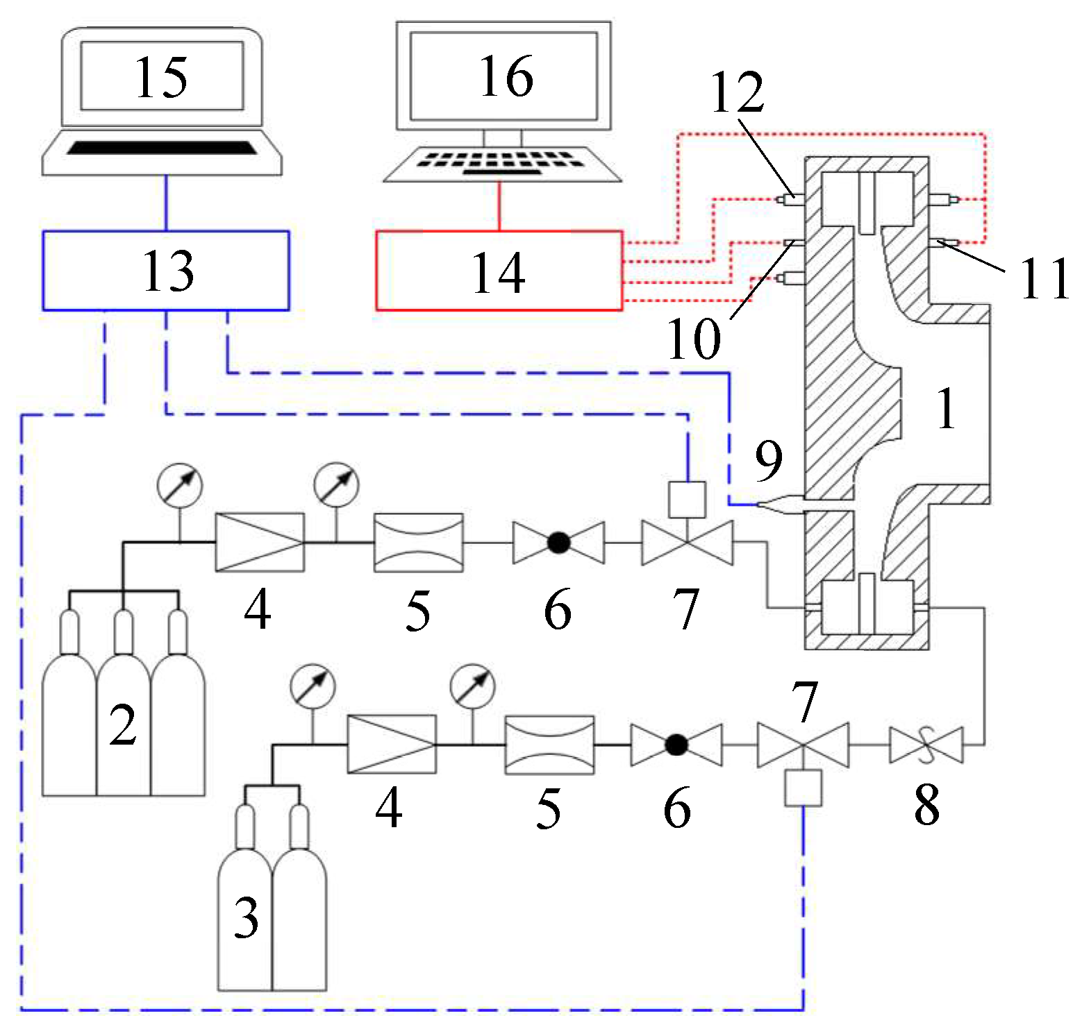
Figure 2.
Schematic of disk-shaped RDE (unit: mm, 1-H2 supply pipeline; 2-H2 plenum; 3-injection surface; 4-air plenum; 5-air supply pipeline; 6-spark plug; 7-combustor; 8-ion probe; 9-piezoresistive sensor; 10-piezoelectric sensor; 11-outlet): (a) schematic diagram of engine; (b) RDC instrumentation schematic; (c) schematic diagram of ion probe measurement system.
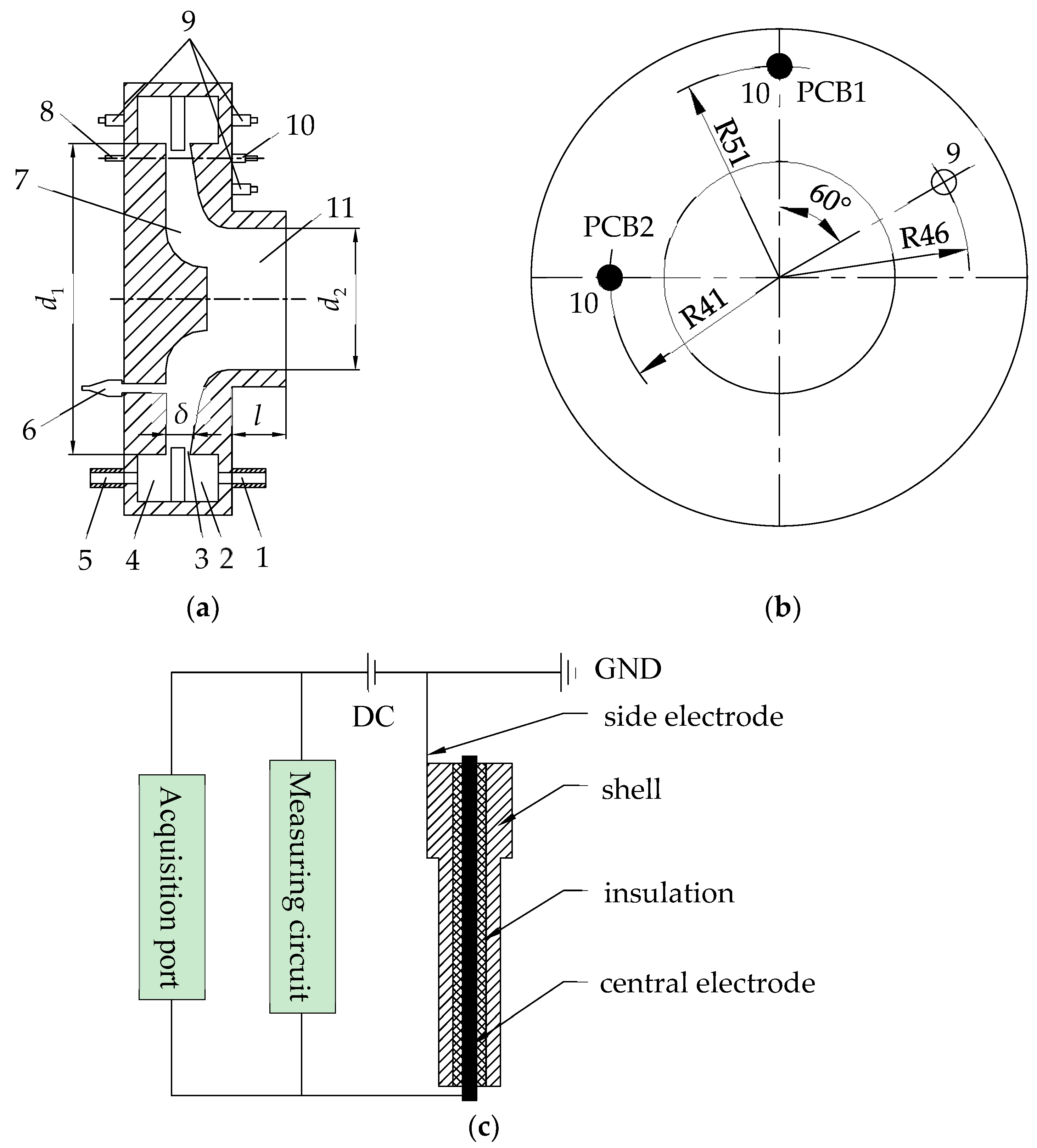
Figure 3.
Dynamic pressure traces in the combustor with different convergent ratios (206 g/s, ER = 1.58): (a) CR = 1.08, #1; (b) FFT result of p1, #1; (c) CR = 1.36, #2; (d) FFT result of p1, #2; (e) CR = 1.70, #3; (f) FFT result of p1, #3. In subfigure (a), the arrow (1) represents the pressure peak captured by PCB1; the arrow (2) represents the pressure peak captured by PCB2; the arrow (3) represents the secondary peak captured by PCB2. In subfigure (c), the arrows represent the platform zone.
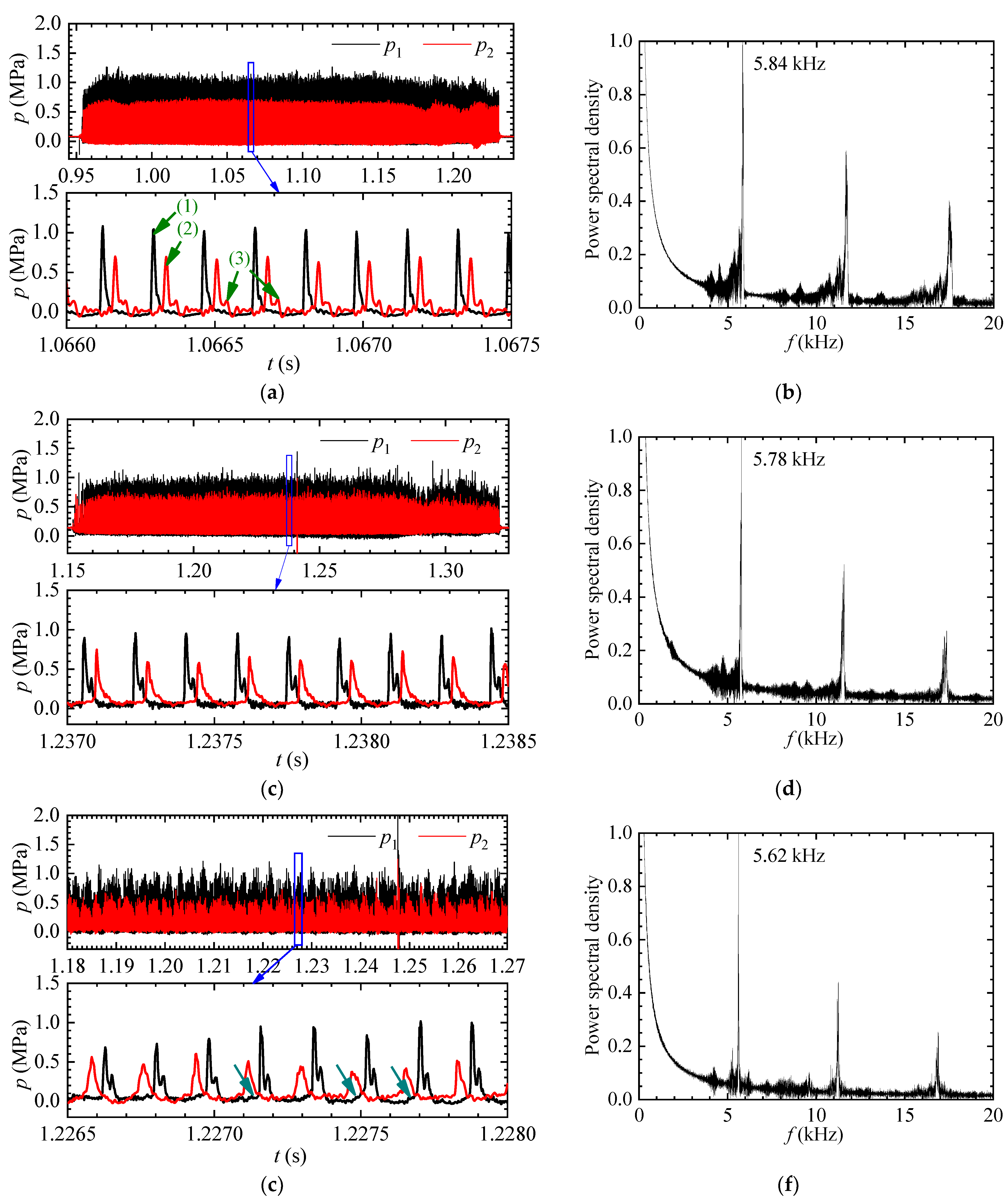
Figure 4.
Comparison of ion signal and dynamic pressure curves (#2).

Figure 5.
Ion signal curve in the combustor (#3): (a) ion signal trace; (b) partially enlarged view of ion curve within one low-frequency oscillation period; (c) FFT result of I1. The ion signal circled by the blue dashed box in subfigure (a) corresponds to the ion signal shown in subfigure (b). In subfigure (b), the arrow (1) represents the regions where the troughs of the ion signal do not return to zero; the arrow (2) indicates the regions where the peak of the ion voltage approaches zero.
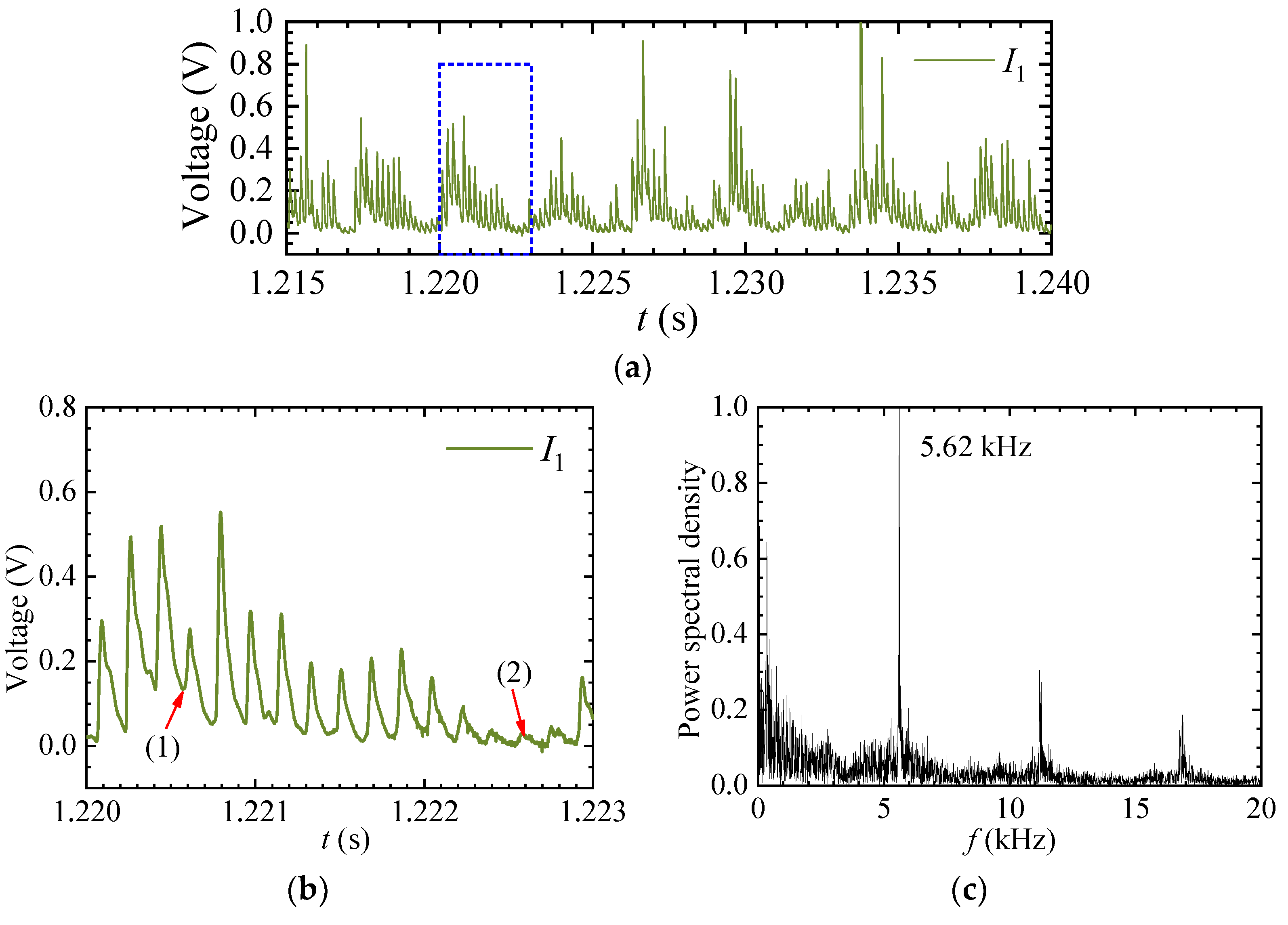
Figure 6.
Effect of convergent ratio on the detonation-wave parameters (206 g/s, monitoring point: 102 mm).
Figure 6.
Effect of convergent ratio on the detonation-wave parameters (206 g/s, monitoring point: 102 mm).
Figure 7.
Detonation-wave propagating velocity variation at different convergent ratios and equivalence ratios (206 g/s, monitoring point: 102 mm; SW: single-wave mode; SDW: symmetric dual-wave mode; ADW: asymmetric dual-wave mode).
Figure 7.
Detonation-wave propagating velocity variation at different convergent ratios and equivalence ratios (206 g/s, monitoring point: 102 mm; SW: single-wave mode; SDW: symmetric dual-wave mode; ADW: asymmetric dual-wave mode).

Figure 8.
Effect of convergent ratio on the RDW propagation mode (282 g/s, ER = 1.15): (a) CR = 1.08, #4; (b) CR = 1.36, #5; (c) CR = 1.70, #6.
Figure 8.
Effect of convergent ratio on the RDW propagation mode (282 g/s, ER = 1.15): (a) CR = 1.08, #4; (b) CR = 1.36, #5; (c) CR = 1.70, #6.
Figure 9.
Effect of convergent ratio on the detonation-wave parameters (282 g/s, monitoring point: 102 mm).
Figure 9.
Effect of convergent ratio on the detonation-wave parameters (282 g/s, monitoring point: 102 mm).
Figure 10.
Distribution of RDE operation modes with mass flow rate at different convergent ratios (USW: unstable single-wave mode; SW: single-wave mode; SDW: symmetric dual-wave mode; ADW: asymmetric dual-wave mode; ADW/SDW: asymmetric dual-wave and symmetric dual-wave mode; LFI: low frequency instability): (a) engine M1 (CR = 1.08); (b) engine M2_3 (CR = 1.36); (c) engine M3 (CR = 1.70); (d) comparison of frequency at different convergent ratios.
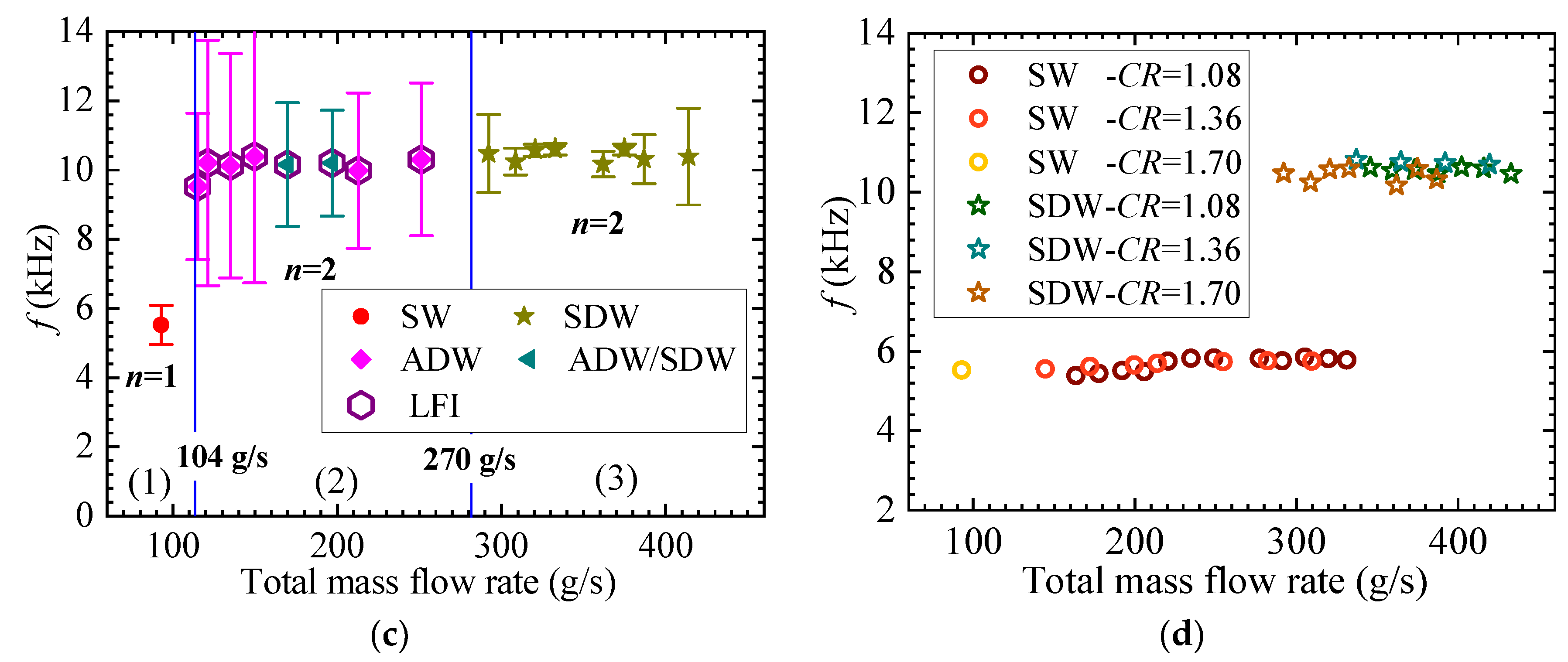
Figure 11.
RDE stable operation range of equivalence ratio at different convergent ratios (206 g/s, F: failure of initiation; SW: single-wave mode; SW/ADW: single-wave and asymmetric dual-wave mode; SDW: symmetric dual-wave mode; ADW: asymmetric dual-wave mode; LFI: low-frequency instability).
Figure 11.
RDE stable operation range of equivalence ratio at different convergent ratios (206 g/s, F: failure of initiation; SW: single-wave mode; SW/ADW: single-wave and asymmetric dual-wave mode; SDW: symmetric dual-wave mode; ADW: asymmetric dual-wave mode; LFI: low-frequency instability).

Figure 12.
Dynamic pressure traces in the RDC with different length outlets (140 g/s, ER = 1.18, CR = 1.36): (a) l = 20 mm, #7; (b) l = 30 mm, #8; (c) l = 46 mm, #9; (d) l = 60 mm, #10; (e) l = 80 mm, #11. In subfigures (c) and (e), the arrows (1) represent the secondary peak captured by PCB1.As shown in Figure 12, in case #7, RDW always propagates in a stable single-wave mode in the combustor with different outlet lengths. The waveforms of the dynamic pressure trace obtained in the combustors are basically consistent, and the curves show a characteristic of “sharp rise and falling slowly” in one cycle, which is in line with the pressure curve characteristics of detonation waves.
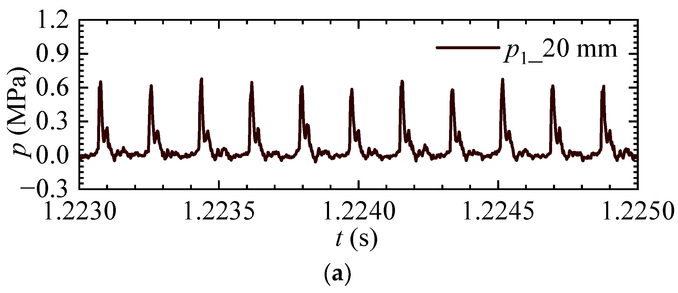
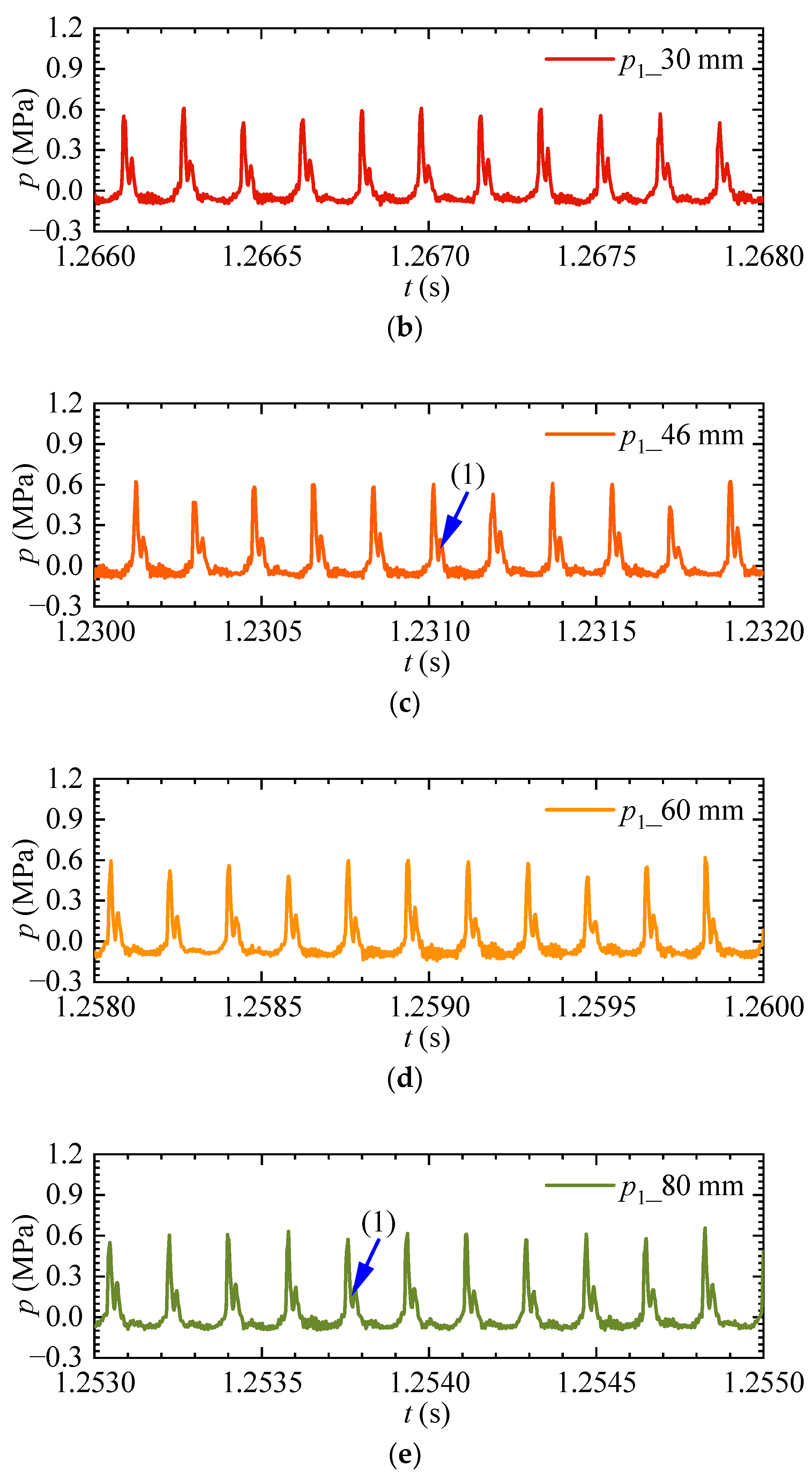
Figure 13.
Detonation-wave parameters variation at different convergent ratios and mass flow rates (ER = 1.20, monitoring point: 102 mm, SW: single-wave mode; SDW: symmetric dual-wave mode; ADW: asymmetric dual-wave mode): (a) velocity; (b) pressure peak.
Figure 13.
Detonation-wave parameters variation at different convergent ratios and mass flow rates (ER = 1.20, monitoring point: 102 mm, SW: single-wave mode; SDW: symmetric dual-wave mode; ADW: asymmetric dual-wave mode): (a) velocity; (b) pressure peak.

Table 1.
Geometric parameters of different engines.
| No. | d1/mm | d2/mm | l/mm | Inlet Area/mm2 | Minimum Area/mm2 | Convergent Ratio |
|---|---|---|---|---|---|---|
| M1 | 120 | 56 | 46 | 2450.44 | 2277.19 | 1.08 |
| M2_3 | 120 | 50 | 46 | 2450.44 | 1805.19 | 1.36 |
| M3 | 120 | 46 | 46 | 2450.44 | 1441.52 | 1.7 |
| M2_1 | 120 | 50 | 20 | 2450.44 | 1805.19 | 1.36 |
| M2_2 | 120 | 50 | 30 | 2450.44 | 1805.19 | 1.36 |
| M2_4 | 120 | 50 | 60 | 2450.44 | 1805.19 | 1.36 |
| M2_5 | 120 | 50 | 80 | 2450.44 | 1805.19 | 1.36 |
Table 2.
Experimental conditions.
| Case | Mass Flow Rate of H2 (g/s) | Mass Flow Rate of Air (g/s) | Equivalence Ratio (ER) | Convergent Ratio (CR) | Outlet Length (mm) | Mode |
|---|---|---|---|---|---|---|
| #1 | 9.5 | 206 | 1.58 | 1.08 | 46 | SW |
| #2 | 9.5 | 206 | 1.58 | 1.36 | 46 | SW |
| #3 | 9.5 | 206 | 1.58 | 1.70 | 46 | SW |
| #4 | 9.5 | 282 | 1.15 | 1.08 | 46 | SW |
| #5 | 9.5 | 282 | 1.15 | 1.36 | 46 | SW |
| #6 | 9.5 | 282 | 1.15 | 1.70 | 46 | SDW |
| #7 | 4.8 | 140 | 1.18 | 1.36 | 20 | SW |
| #8 | 4.8 | 140 | 1.18 | 1.36 | 30 | SW |
| #9 | 4.8 | 140 | 1.18 | 1.36 | 46 | SW |
| #10 | 4.8 | 140 | 1.18 | 1.36 | 60 | SW |
| #11 | 4.8 | 140 | 1.18 | 1.36 | 80 | SW |
Disclaimer/Publisher’s Note: The statements, opinions and data contained in all publications are solely those of the individual author(s) and contributor(s) and not of MDPI and/or the editor(s). MDPI and/or the editor(s) disclaim responsibility for any injury to people or property resulting from any ideas, methods, instructions or products referred to in the content. |
© 2023 by the authors. Licensee MDPI, Basel, Switzerland. This article is an open access article distributed under the terms and conditions of the Creative Commons Attribution (CC BY) license (https://creativecommons.org/licenses/by/4.0/).
Share and Cite
MDPI and ACS Style
Xia, Z.; Ma, H.; Ge, G.; He, Y.; Zhou, C. Effect of Combustor Outlet Geometry on Operating Characteristics of Disk-Shaped Rotating Detonation Engine. Aerospace 2023, 10, 732. https://doi.org/10.3390/aerospace10080732
AMA Style
Xia Z, Ma H, Ge G, He Y, Zhou C. Effect of Combustor Outlet Geometry on Operating Characteristics of Disk-Shaped Rotating Detonation Engine. Aerospace. 2023; 10(8):732. https://doi.org/10.3390/aerospace10080732
Chicago/Turabian StyleXia, Zhenjuan, Hu Ma, Gaoyang Ge, Yong He, and Changsheng Zhou. 2023. "Effect of Combustor Outlet Geometry on Operating Characteristics of Disk-Shaped Rotating Detonation Engine" Aerospace 10, no. 8: 732. https://doi.org/10.3390/aerospace10080732
Note that from the first issue of 2016, this journal uses article numbers instead of page numbers. See further details here.