Article

A Comparison of the Damage Tolerance of AA7075-T6, AA2024-T3, and Boeing Space, Intelligence, and Weapons Systems AM-Built LPBF Scalmalloy

1
ARC Industrial Transformation Training Centre on Surface Engineering for Advanced Materials, School of Engineering, Swinburne University of Technology, John Street, Hawthorn, Victoria 3122, Australia
2
Centre of Expertise for Structural Mechanics, Department of Mechanical and Aerospace Engineering, Monash University, Clayton, Victoria 3800, Australia
3
Boeing Space, Intelligence, and Weapons Systems, Arlington, VA 22202, USA
4
Structures Division, Naval Air Systems Command, Patuxent River, MD 20670, USA
*
Author to whom correspondence should be addressed.
Aerospace 2023, 10(8), 733; https://doi.org/10.3390/aerospace10080733
Submission received: 4 July 2023 / Revised: 13 August 2023 / Accepted: 19 August 2023 / Published: 20 August 2023
(This article belongs to the Section Aeronautics)

Abstract

:
This paper first presents the results of an experimental study into the damage tolerance of AA7075-T6, which is widely used in both fixed- and rotary-wing aircraft, space structures, and laser bed powder fusion (LBPF) Scalmalloy specimens built by Boeing Space, Intelligence, and Weapons Systems. To this end, four single edge notch AA7075-T6 specimens and four identical single edge notch LBPF Scalmalloy specimens were tested. The resultant crack growth curves reveal that Boeing Space, Intelligence, and Weapons Systems AM-built Scalmalloy is more damage tolerant than conventionally built AA7075-T6. This finding leads to the observation that the da/dN versus ΔK curves associated with Scalmalloy and conventionally manufactured AA2024-T3 are similar. These findings highlight the potential for Boeing Space, Intelligence, and Weapons Systems AM-built Scalmalloy to be used to extend the operational lives of military aircraft by the on-demand printing of limited-life Scalmalloy replacement parts.

1. Introduction

Scalmalloy®, a high-strength aluminium/magnesium/scandium (Al-Mg-Sc) alloy, was developed by Airbus for the additive manufacturing of aluminium alloy aerospace parts [1]. A US Navy study into additive manufactured (AM) aluminium alloys [2] found that, of the various AM aluminium alloys assessed, Scalmalloy® had superior tensile strength, Young’s modulus, yield strength, and elongation to failure. A subsequent paper by Jones et al. [3] revealed that Scalmalloy® had a tensile strength, Young’s modulus, yield strength, and an elongation to failure that were comparable to the commonly used aerospace-quality aluminium alloys, AA7050-T7451 and AA7075-T7351, and superior to the AM aluminium alloys Al7Si0.6Mg and Al10SiMg, which are now increasingly being used in space applications, and the AM aluminium alloy 7A77, see Table 1.
As noted in the United States Air Force (USAF) Structures Bulletin EZ-19-01 [7], the certification of an AM part requires a durability and damage tolerance (DADT) assessment that is consistent with the certification guidelines delineated in MIL-STD-1530D [8] and the United States (US) Joint Services Structural Guidelines JSSG2006 [9]. The requirements delineated in the National Aeronautics and Space Administration (NASA) Fracture Control Handbook [10] for space structures are similar to those outlined in [8,9]. In this context, the papers by Jones et al. [3,11] were the first to reveal that Scalmalloy has similar da/dN versus ΔK curves to those of the aluminium alloys AA7050-T7451, AA7075-T7351, AA6061-T6, and AA5754. As such, Scalmalloy® would appear to be an ideal candidate for use in both aircraft, drones, satellites, and space structures, as well as for limited life replacement parts for military aircraft, both rotary and fixed wing.
Consequently, noting that:
(i)
AA7075-T6 and AA7075-T7351 have similar da/dN versus ΔK curves and that both alloys are widely used in a range of rotary-wing aircraft (helicopters), viz., Blackhawk, Seahawk, Chinook, Apache, etc., as well as in military transport and maritime aircraft (C-130J, P3C Orion), weapon pylons (F-15), etc.;
(ii)
The USAF has been flying AM Ti-6Al-4V weapons pylons on F-15 aircraft as a replacement to a damaged AA7075-T6 part for almost twenty years [12];
(iii)
Boeing Defence and Space have flight demonstrator parts, built using the aluminium alloy 7A77, on US Army Chinook helicopters [13].
The objective of this preliminary study was to directly compare crack growth in identical AA7075-T6 and laser powder bed fusion (LPBF)-built Scalmalloy specimens tested in the same servo-hydraulic fatigue test facility under the same loads and by the same operators. (Here, it should be noted that laser powder bed fusion (LPBF) is currently one of the most widely used AM processes. In this process, a part is built layer upon layer, using a high-energy laser to selectively fuse the powder into a computer-controlled predetermined shape).
The result of this study reveal that Scalmalloy would appear to have a superior damage tolerance to that of the conventionally manufactured aluminium alloy AA7075-T6. This finding subsequently leads to the observation that the da/dN versus ΔK curves associated with Scalmalloy and conventionally manufactured AA2024-T3, which is used on Boeing 737, 747, 777, Airbus A320, the Boeing P8 Maritime patrol/reconnaissance aircraft, etc., are similar. As a result, Boeing Space, Intelligence, and Weapons Systems AM Scalmalloy would appear to be particularly attractive for use on a range of military aircraft and helicopters, as well as for space applications.

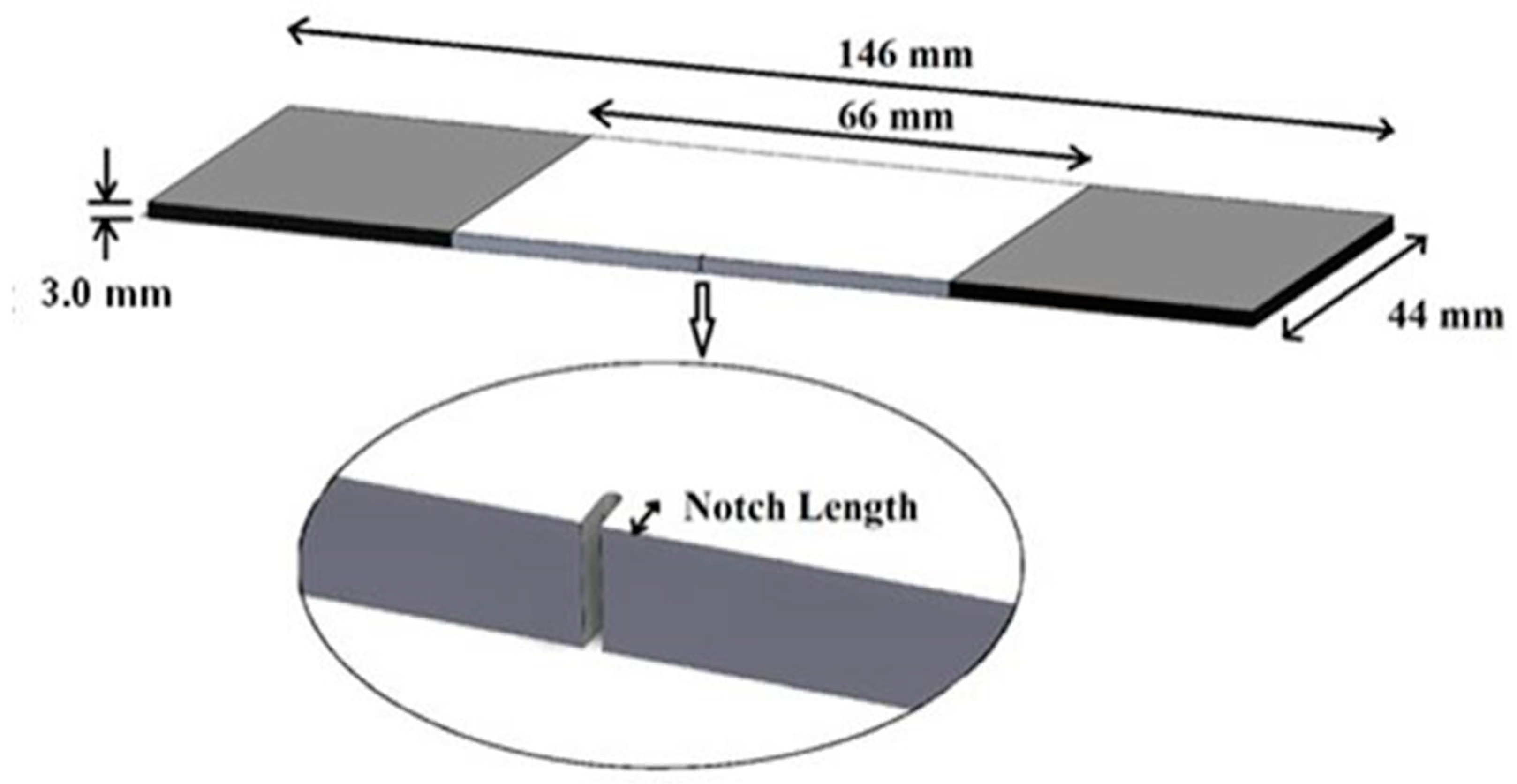
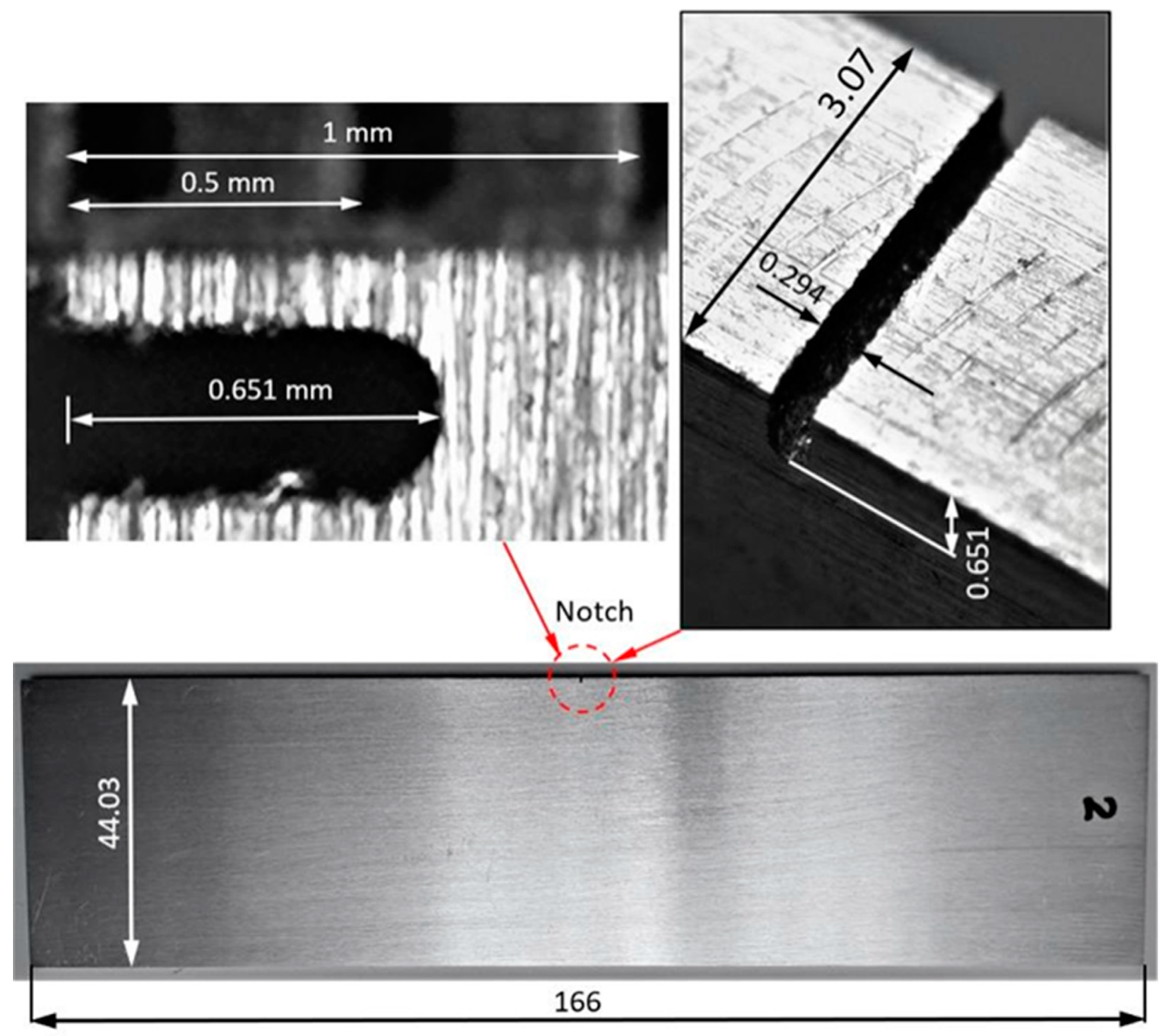
2. Materials and Methods
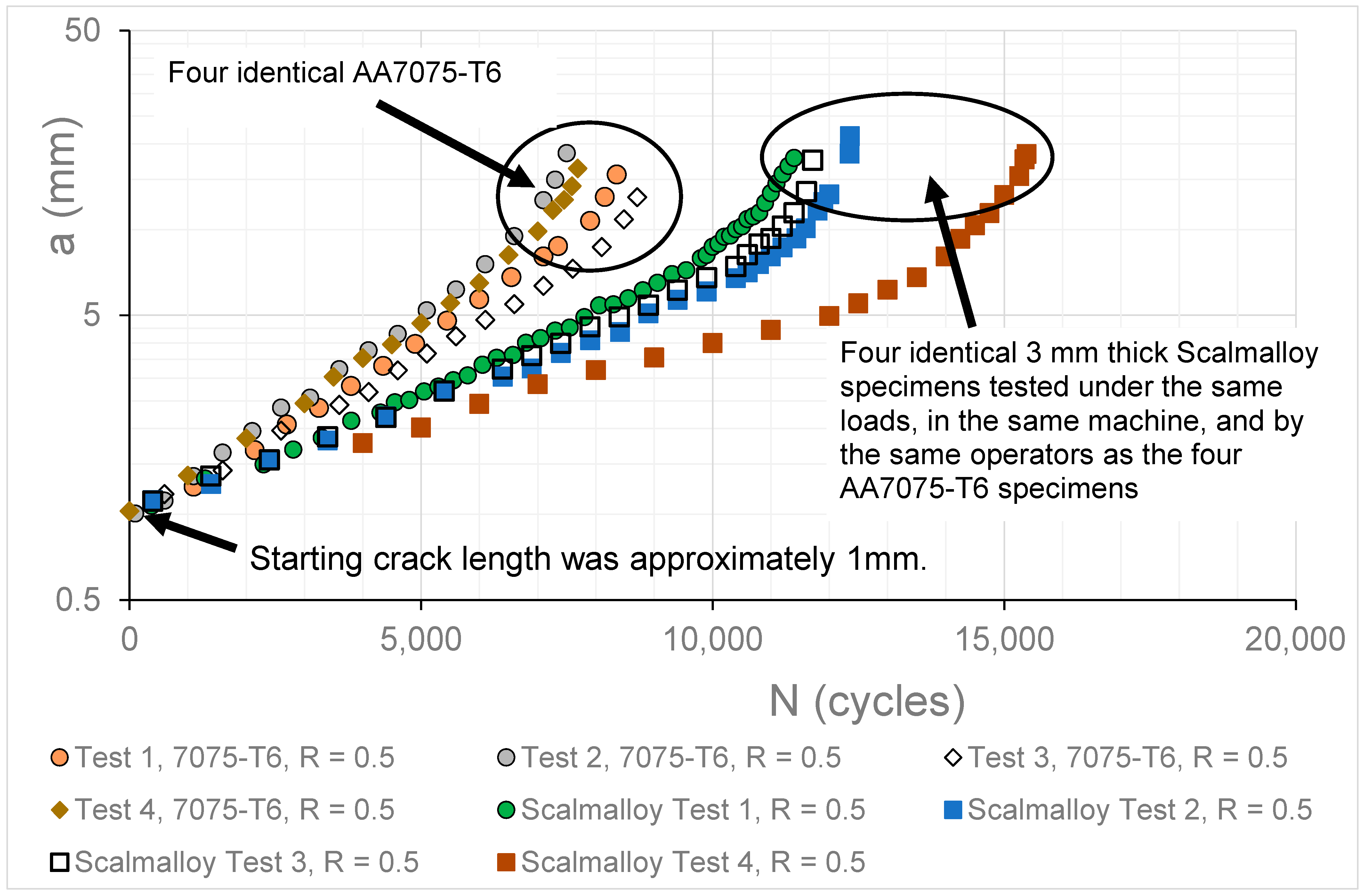
This paper addresses a research gap associated with the use of Scalmalloy to build limited life parts for legacy military aircraft, viz., a direct comparison between its damage tolerance and that of a widely used conventionally manufactured aluminium alloy that is extensively used in both fixed- and rotary-wing aircraft. In this instance, the comparison is between the aluminium alloy AA7075-T6, which is used in military transport, maritime patrol aircraft, combat aircraft, helicopters, and weapon pylons, and LPBF Scalmalloy.
As a result of material availability, it was decided to test four 3 mm thick AA7075-T6 aluminium alloy ASTM single edge notch tension (SENT) [14] specimens and four geometrically identical LPBF Scalmalloy specimens. The LPBF Scamalloy specimens were printed by Boeing Space, Intelligence, and Weapons Systems to a (Boeing) qualified and controlled production process. The AA7075-T6 and the Scalmalloy specimens were all subjected to the same remote stress, the same constant amplitude fatigue load spectrum, tested in the same servo-hydraulic MTS 100 kN fatigue test facility, and tested by the same operators.
The dimensions and geometry of the test specimens are shown in Figure 1. The specimens had a width of 44 mm; the total length of the specimens was 146 mm, and the length of the working sections was 66 mm. The specimens’ thickness was approximately 3.0 mm. All specimens contained an initial, nominally 0.3 mm wide “machined” starter notch, see Figure 2. The length of the starting notch in these tests was nominally 0.65 mm, see Figure 2. The tests were performed in an MTS 100 kN servo-hydraulic test facility using a stress ratio (R = σmin/σmax) of R = 0.5 and a maximum remote stress (σmax) of approximately 204.5 MPa. This stress was used because it represents 115% of the maximum design limit stress seen in the AA7075-T651 wing skin in operational P3C (Orion) aircraft [15]. The frequency used in the test was 10 Hz.
Crack growth was monitored using digital cameras located on either side of the specimen. One such digital image is shown in Figure 3. The resultant crack length versus cycles curves were then directly compared.

3. Test Results

The test specimens were first pre-cracked, under the constant amplitude load spectrum described above, to a length of 1 mm. This length includes the length (0.65 mm) of the initial starter notch. (The rational for this level of pre-cracking is discussed in the Appendix A.) The resultant crack length (a) versus cycles (N) curves associated with the various tests are shown in Figure 4, as well as in Figure 5, which focuses on the initial crack length versus cycles history. Here, it should be noted that, as mentioned above, we compared the crack growth histories starting after a length of 1 mm. This was conducted to ensure that the crack lengths associated with these tests were representative of that required in the USAF Damage Tolerant Design Handbook [16,17] for the damage tolerance assessment of an airframe, namely, 1.27 mm (0.05 inch).
Inspecting Figure 5, we can observe the following:
(a)
Except for the region close to the final failure, there was a near linear relationship between ln(a) and the number of cycles (N);
(b)
This relationship is similar to that seen in operational aircraft in service with the USAF [18], in the Royal Australian Air Force (RAAF)’s operational usage of the Boeing F/A-18 Classic Hornet [19], and in a range of full-scale fatigue tests [20];
(c)
The initial slope(s) of the ln(a) versus N curves associated with the tests on the Boeing Defence and Space AM Scalmalloy specimens were significantly lower than the slopes of the corresponding curves for the conventionally manufactured AA7075-T6 specimens. (This observation is discussed in more detail in Section 4);
(d)
The Scalmalloy specimens had longer lives than the AA7075-T6 specimens;
(e)
As such, the damage tolerance of the Boeing Space, Intelligence, and Weapons Systems AM Scalmalloy specimens would appear to be superior to that of conventionally manufactured AA7075-T6.

4. Comparing the Crack Growth Rates

It is instructive to compare the fastest growing cracks in both the AA7075-T6 and the Scalmalloy tests. This is provided in Figure 5. Here, we see that, as predicted in [21] and as also noted above, for this geometry the initial crack length versus cycles history (i.e., for crack lengths between approximately 1 and 8 mm) is approximately exponential. Indeed, as shown in Figure 5, in both cases the coefficient of discrimination (R2) is greater than 0.997. This means that for these tests, for crack lengths between (approximately) 1 and (approximately) 8 mm, the crack growth rate (da/dN) is essentially proportional to the crack length (a). It also follows that the ratio of the fastest crack growth rate in the Scalmalloy specimen tests to that of the fastest crack growth rate seen in the tests in the AA7075-T6 tests was approximately 0.62.
This finding suggests that Scalmalloy may have a da/dN versus ΔK curve that is closer to that of conventionally built aluminium alloy AA2024-T3, which as mentioned above is widely used in both fixed- and rotary-wing aircraft, than that of conventionally manufactured AA7075-T6. To investigate this hypothesis, Figure 6 presents the R = 0.1 and R = 0.7 da/dN versus ΔK curves presented in [3] for Scalmalloy and R = 0.1 and R = 0.75 da/dN versus ΔK curves taken from the Nasgro database. The Nasgro identifiers associated with these two tests are given in Figure 6.
Figure 6 reveals that, allowing for experimental error, the da/dN versus ΔK curves associated with these two different materials are indeed quite similar. However, as shown in Table 1, Scalmalloy has a yield stress (σy) and an ultimate strength (σy) that is markedly superior to that of AA2024-T3. The strain to failure associated with Scalmalloy is lower than that of AA2024-T3, see Table 1. Consequently, noting that the USAF Mil-STD-1530D [8] states that there must be no yield at a 100% design limit load (DLL), and the US Joint Service Structural Guidelines JSSG2006 [9] states that there must be no yield at a 115% design limit load (DLL), it would appear that, when compared to conventionally manufactured AA2024-T3, Scalmalloy has the advantage of having:
(i)
A similar da/dN versus ΔK curve;
(ii)
Whilst allowing for parts that could take higher loads without exceeding the no yield requirements inherent in MIL-STD-1530D and JSSG2006.
This further suggests that Scalmalloy is particularly attractive for both fixed- and rotary-wing military aircraft and space vehicles. (Design limit load is the maximum load that is seen in an operational aircraft).
At this stage, it should be noted that the USAF Structures Bulletin EZ-19-01 explains that the airworthiness certification of an additively manufactured part requires a durability analysis and that, as mandated in Section 5 of USAF MIL-HDBK-1530D, the role of testing is merely to validate/correct the analysis. As such, it is essential that tests to determine the small crack da/dN versus ΔK curves, which are needed to perform a valid durability assessment, be determined. This data set does not currently exist. That said, noting that the crack growth curves presented in Figure 6 for Scalmalloy and AA2024-T3 are similar, it is conjectured that their small crack growth curves should also be similar.

5. Conclusions

Noting that AA7075-T6 is widely used by both fixed- and rotary-wing military aircraft, as well as in space structures, the initial objective of this study was to directly compare crack growth in identical AA7075-T6 and Scalmalloy specimens tested in the same servo-hydraulic facility under the same stresses and by the same operators. The experimental data reveal that Boeing Space, Intelligence, and Weapons Systems AM-built Scalmalloy appears to be more damage tolerant than the conventionally built aluminium alloy AA7075-T6. As a result, Boeing Space, Intelligence, and Weapons Systems printed Scalmalloy would appear to be particularly attractive for use on a range of military aircraft, as well as for space applications. It also highlights the potential for Boeing Space, Intelligence, and Weapons Systems Scalmalloy to be used to extend the operational lives of military aircraft through the on-demand printing of limited life Scalmalloy replacement parts.
The results of this initial test program have led to the hypothesis that the da/dN versus ΔK curves associated with Scalmalloy and conventionally built AA2024-T3 should be similar. This hypothesis was, subsequently, validated by comparison to AA2024-T3 da/dN versus ΔK curves taken from the Nasgro database. This observation subsequently led to the conjecture that the small crack da/dN versus ΔK curves associated with Scalmalloy and AA2024-T3, which are needed for a durability analysis, should be similar. If this hypothesis can be confirmed, then given that:
(i)
Scalmalloy has a yield stress significantly greater than that of AA2024-T3;
(ii)
AA2024-T3 is widely used in both fixed- and rotary-wing aircraft;
(iii)
MIL-STD-1530D mandates that there must be no yield at 100% DLL and the US Joint Services Structural Guidelines JSSG2006 states that there should be no yield at 115% DLL, the use of Scalmalloy for both fixed- and rotary-wing aircraft, and drones would appear to be very attractive.
As such, the next stage in the study will involve the determination of valid upper bound da/dN versus ΔK curves for the growth of short cracks in AA2024-T3.

Author Contributions

Project overview in Australia—R.J.; Testing—D.P.; Funding and initial analysis—A.A.; Conceptualisation—R.W.A., N.D.P. and R.J.; Program funding and program overview at Boeing—R.W.A.; 1st Draft of the paper—R.J. and A.A.; Overview and evaluation of the final paper—R.W.A. and N.D.P.; Specimen manufacture—N.D.S. All authors have read and agreed to the published version of the manuscript.

Funding

Rhys Jones and Andrew Ang would like to acknowledge funding provided via Boeing Service Contract No. 2399071.

Data Availability Statement

The data are not yet publicly available due to the ongoing nature of this project. The data will be available on completion of the study.

Acknowledgments

The authors gratefully acknowledge the contributions of Nicole Jain of The Boeing Company to the process development and qualification of the Scalmalloy laser powder bed printing process.

Conflicts of Interest

The authors declare no conflict of interest.

Appendix A

Figure A1 presents a typical aluminium alloy ASTM standard compact tension test specimen. Inspecting Figure A1, we see that the minimum crack length associated with such tests is of the order of 10 of mm. This crack length differs significantly with the initial crack length of 1.27 mm (0.05 inch) required in the USAF Damage Tolerant Design Handbook [16] for a damage tolerance assessment. As such, to minimise any potential confusion when comparing crack growth in AA7075-T6 and LPBF Scalmalloy, it was decided to test specimens with initial crack lengths that were similar to the USAF Damage Tolerant Design Handbook [16] requirement. An added advantage of this test specimen geometry is that the resultant crack growth history is exponential and, as such, are representative of that seen in operational aircraft [18,19].
Figure A1. A typical ASTM standard aluminium alloy compact tension (CT) test specimen.
Aerospace 10 00733 g0a1

References

  1. Scalmalloy. Available online: https://www.apworks.de/scalmalloy (accessed on 18 August 2023).
  2. Muhammad, M.; Nezhadfar, P.D.; Thompson, S.; Saharan, A.; Phan, N.; Shamsaei, N. A comparative investigation on the microstructure and mechanical properties of additively manufactured aluminum alloys. Int. J. Fatigue 2021, 146, 106165. [Google Scholar] [CrossRef]
  3. Jones, R.; Cizek, J.; Kovarik, O.; Lang, J.; Ang, A.; Michopoulos, J.G. Describing crack growth in additively manufactured Scalmalloy®. Addit. Manuf. Lett. 2021, 1, 100020. [Google Scholar] [CrossRef]
  4. Begoc, S.; Montredon, F.; Pommatau, G.; Lege, G.; Gas, M.; Eyrignoux, S. Additive manufacturing of Scalmalloy® satellite parts. In Proceedings of the 8th European Conference for Aeronautics and Space Sciences (EUCASS), Madrid, Spain, 1–4 July 2019; Available online: https://www.eucass.eu/doi/EUCASS2019-0677.pdf (accessed on 15 May 2023).
  5. Aerospace Specification Metals Inc. Available online: http://asm.matweb.com/ (accessed on 15 May 2023).
  6. Martin, J.H.; Yahata, B.D.; Hundley, J.M.; Mayer, J.A.; Schaedler, T.A.; Pollock, T.M. 3D printing of high-strength aluminium alloys. Nature 2017, 245, 365–369. [Google Scholar] [CrossRef] [PubMed]
  7. Durability and Damage Tolerance Certification for Additive Manufacturing of Aircraft Structural Metallic Parts; Structures Bulletin EZ-19-01; Wright Patterson Air Force Base: Dayton, OH, USA, June 2019; Available online: https://daytonaero.com/usaf-structures-bulletins-library/ (accessed on 13 May 2023).
  8. MIL-STD-1530D; Department of Defense Standard Practice Aircraft Structural Integrity Program (ASIP). Military and Government Specs & Standards (Naval Publications and Form Center) (NPFC): Philadelphia, PA, USA, 13 October 2016. Available online: http://everyspec.com/MIL-STD/MIL-STD.../download.php?spec=MIL-STD-1530D (accessed on 13 May 2023).
  9. Department of Defense. Joint Service Specification Guide; Aircraft Structures, JSSG-2006; US Department of Defense: Washington, DC, USA, October 1998; Available online: http://everyspec.com/USAF/USAF-General/JSSG-2006_10206/ (accessed on 13 May 2023).
  10. NASA-HDBK-5010; Fracture Control Handbook for Payloads, Experiments, and Similar Hardware. NASA: Washington, DC, USA, May 2005; Revalidated 2012. Available online: https://standards.nasa.gov/standard/nasa/nasa-hdbk-5010 (accessed on 2 May 2023).
  11. Jones, R.; Cizek, J.; Kovarik, O.; Ang, A.; Champagne, V. Observations on comparable aluminium alloy crack growth curves: Additively manufactured Scalmalloy® as an alternative to AA5754 and AA6061-T6 alloys? Addit. Manuf. Lett. 2022, 2, 100026. [Google Scholar] [CrossRef]
  12. Kinsella, M.E. The Air Force Qualification Pathway and Its Challenges for AM, Summary Report: Joint Federal Aviation Administration–Air Force Workshop on Qualification/Certification of Additively Manufactured Parts; Goelick, M., Ed.; DOT/FAA/TC-16/15; Federal Aviation Administration: Washington, DC, USA, 55–62 June 2016. Available online: https://www.tc.faa.gov/its/worldpac/techrpt/tc16-15.pdf (accessed on 13 May 2023).
  13. Available online: https://www.metal-am.com/metal-3d-printed-components-for-chinook-helicopter-undergo-army-flight-tests/ (accessed on 13 May 2023).
  14. ASTM E647-13; Measurement of Fatigue Crack Growth Rates. ASTM: West Conshohocken, PA, USA, 2013.
  15. Iyyer, N.; Sarkar, S.; Merrill, R.; Phan, N. Aircraft life management using crack initiation and crack growth models—P-3C Aircraft experience. Int. J. Fatigue 2007, 29, 1584–1607. [Google Scholar] [CrossRef]
  16. Gallagher, J.P.; Giessler, F.J.; Berens, A.P.; Wood, H.A. USAF Damage Tolerant Design Handbook: Guidelines for the Analysis and Design of Damage Tolerant Aircraft Structures; AFWAL-TR-82-3073; Wright-Patterson Air Force Base: Dayton, OH, USA, 1984. [Google Scholar]
  17. Miedlar, P.C.; Berens, A.P.; Gunderson, A.; Gallagher, J.P. Analysis and Support Initiative for Structural Technology (ASIST), AFRL-VA-WP-TR-2003-3002. 2003. Available online: https://apps.dtic.mil/sti/pdfs/ADA411872.pdf (accessed on 18 August 2023).
  18. Berens, A.P.; Hovey, P.W.; Skinn, D.A. Risk Analysis for Aging Aircraft Fleets-Volume 1: Analysis; WL-TR-91-3066; Flight Dynamics Directorate; Wright Laboratory: New Haven, CT, USA; Air Force Systems Command, Wright-Patterson Air Force Base: Dayton, OH, USA, October 1991. [Google Scholar]
  19. Main, B.; Molent, L.; Singh, R.; Barter, S. Fatigue crack growth lessons from thirty-five years of the Royal Australian Air Force F/A-18 A/B hornet aircraft structural integrity program. Int. J. Fatigue 2020, 133, 105426. [Google Scholar] [CrossRef]
  20. Molent, L.; Barter, S.A. A comparison of crack growth behaviour in several full-scale airframe fatigue tests. Int. J. Fatigue 2007, 9, 1090–1099. [Google Scholar] [CrossRef]
  21. Jones, R.; Peng, D. A Building Block Approach to Sustainment and Durability Assessment: Experiment and Analysis. In Comprehensive Structural Integrity, 2nd ed.; Aliabadi, F.M.H., Soboyejo, W., Eds.; Elsevier: Oxford, UK, 2023; Volume 7, pp. 73–101. ISBN 978-0-12-822944-6. [Google Scholar]
Figure 1. Specimen geometry and dimensions.
Aerospace 10 00733 g001
Figure 2. Single edge notch tension specimen geometry.
Aerospace 10 00733 g002
Figure 3. Typical crack growth from a notch.
Aerospace 10 00733 g003
Figure 4. Comparison of the 3 mm thick AA7075-T6 and Scalmalloy crack growth histories.
Aerospace 10 00733 g004
Figure 5. Comparison of the fastest growing cracks in AA7075-T6 and Scalmalloy.
Aerospace 10 00733 g005
Figure 6. Comparison of the crack growth rate curves associated with Scalmalloy and AA2024-T3.
Aerospace 10 00733 g006
Table 1. Comparison of the values of σy, σult, and strain to failure.
σy (MPa)σult (MPa)Strain to Failure ( mm mm )
LPBF Scalmalloy®, heat treated at 325 °C for 4 h [2]5085300.16
A-l7Si-0.6Mg, heat treated [4]-3300.05
AA7050-T7451 [5]4325210.11
AA7075-T6 [5]5035750.11
AA7075-T7351 [5]4565180.15
Al-7Si-0.6Mg, heat treated [3]-3300.05
AM 7A77 [6]3754250.55
AA2024-T3 [5]3454830.18
Disclaimer/Publisher’s Note: The statements, opinions and data contained in all publications are solely those of the individual author(s) and contributor(s) and not of MDPI and/or the editor(s). MDPI and/or the editor(s) disclaim responsibility for any injury to people or property resulting from any ideas, methods, instructions or products referred to in the content.

