
Guidance and Control for Safe Contactless Plume Impingement Operations to Detumble an Uncooperative Spacecraft

Department of Aerospace Science and Technology, Politecnico di Milano, 34, Via La Masa, 20156 Milan, Italy
*
Author to whom correspondence should be addressed.
Aerospace 2024, 11(3), 224; https://doi.org/10.3390/aerospace11030224
Submission received: 30 January 2024
/
Revised: 5 March 2024
/
Accepted: 11 March 2024
/
Published: 13 March 2024
(This article belongs to the Section Astronautics & Space Science)
Abstract
:In recent years, the interest in proximity operations to uncooperative and non-collaborative objects has been growing and and demanding for specific technology advances to tackle these challenging cases of in-orbit servicing and removal missions. Indeed, these architectures hold a crucial role in guaranteeing future sustainable and efficient space operations. One of the main challenges of conducting robotic operations with a chaser in close proximity to an uncooperative object stems from its rotational motion. A tumbling motion of a large target object may require a costly and complex synchronisation of the servicer relative trajectory to the capture point and hinder the safety of operations due to rotating appendages. In this paper, the plume impingement strategy is employed to control the target’s tumbling motion in a contactless fashion, thus guaranteeing feasible approach and capture operations. Specifically, guidance and control strategies to be employed during this delicate and complex operation are devised, focusing on improving the safety of the trajectory while maximising the efficiency of the impingement effect during proximity flight. Simulations discuss the detumbling of a satellite of a large constellation, critically comparing delta-v cost, trajectory safety and overall time of operations.
1. Introduction
Ensuring the overall sustainability of the in-space environment is paramount for its future utilisation. It is seen that the increase of launches and number of satellites in orbit calls for immediate action. A fundamental change on the space sector is driven by mission architectures of In-Orbit Servicing (IOS) and Active Debris Removal (ADR). IOS focuses on extending mission lifespans, refuelling, and repairing in-orbit satellites to enhance platform revenues and services. Conversely, ADR aims to mitigate the growing space debris population. Servicing missions such as Mission Extension Vehicle 1 (MEV-1) have been successfully operated in orbit to extend the life of a geostationary satellite, with clear advantages in its prolonged service. The capability of refuelling and repairing with a servicer are also investigated, for example through the OSAM-1 mission, former Restore-L, which is being developed currently by NASA. At the same time, ADR mission and removal activities, although not demonstrated yet in orbit, are investigated to mitigate the proliferation of the debris population low Earth orbit [1]. The e.Deorbit study funded by ESA have been performed in the last decade to remove the large inactive ENVISAT from its orbital location, diminishing the threat of in-orbit collisions and fragmentations. Currently, the ClearSpace-1 mission, planned for launch in 2026, is being developed to capture and remove the VESPA payload adaptor and induce its controlled reentry [2].
These mission architectures imply a servicer that operates in proximity to a target object, which can be partially or entirely inactive. Several strategies and technologies have been studied within the space community to remove inactive objects, i.e., debris, from space. The solutions explored all share a common goal: bring the target object away from its current orbital region, inducing either a reentry to comply with the 25-year rule in LEO or moving it to a graveyard orbit. The strategies mainly fall into two main categories: (1) capture removal methods and (2) contactless removal methods. Contact capture methods exploit a system onboard the servicer, which is capable of creating a contact between the servicer and the target and ensure its capture. Following the capture, deorbiting operations of the stack are required to modify the debris orbital state and ensure a safe disposal. Examples of contact methods are robotic arms [3], net mechanisms and harpoon systems [4]. On the other hand, contactless methods studied in the literature feature ion beam strategies [5], laser ablation methods [6] and coulomb electrostatic forces [7]. These methods provide, in general, very low accelerations to the debris, and thus a long time to achieve the required deorbiting actions.
Complexities in approach, operations and capture of a failed object lie in its uncooperativeness and non-collaborativeness. An object is deemed uncooperative when no contact or link with the servicer can be established, hindering the navigation and operation of the formation. On the other hand, the non-collaborativeness is caused by the inability of the target to perform translational and rotational manoeuvres to facilitate the approach and its capture. In this work, the issue of the failed target’s lack of collaboration is addressed. The servicer is often required to perform some robotic operations, for example with one or multiple robotic arms. During these operations, the target state and conditions hold a crucial role. Complexities in the capture and operational safety may arise if the rotational rate of the target is large. In these situations, the servicer is often required to perform synchronisation to the target’s motion to reduce the relative motion between the servicer and the capture point on the target body. One explored strategy is to approach the target along the rotational angular momentum to reduce the relative attitude motion between the target’s surfaces and the servicer platform. This option can be feasible in the situation where the capture point is located along the current angular momentum direction in the target’s body frame. In general, a synchronisation forced motion is required to reduce the relative motion of the capture point to the robotic arm. These motion regimes required by the servicer will increase the operational complexity and the fuel cost and endanger the flight safety.
Furthermore, the rotational motion of uncooperative objects is extremely difficult to be observed and estimated prior to the proximity measurements with the servicer’s onboard sensors in orbit. Methods such as light curve observations [8], satellite laser ranging [9] or passive radar observations [10] from the ground can be employed. However, they often provide only partial information on the object’s rotational motion and with relevant uncertainties. This implies that at the mission design level, the servicer needs to be often over-designed in terms of GNC requirements to ensure the approach and capture success as well as avoid a situation in which it goes into space and then is not able to capture its target. A current strategy to cope with such difficulties is to foresee an additional, precursor, ADR mission to inspect and characterise the target’s status [11,12,13]. Indeed, this represents a costly option. Moreover, studies on a mission to target the removal of multiple targets have been studied [14,15], for which different conditions and rotational states of the target may impose different requirements and capture points, hence substantial complexities at the mission level.
To enable a successful final approach and capture of a target in an IOS and ADR mission, studies on the possibility of influencing and controlling the state of the target to facilitate operations have received increasing attention. In particular, the uncontrolled tumbling motion of the target is seen as a major problem in safe approach and capture. Although these methods have not yet been demonstrated in orbit, the space community is actively working on solutions to ensure the servicer’s ability to modify the target’s rotational state to its desire. Strategies by using contact with the target surfaces to damp its tumbling rate with brush [16] and rods [17,18] have been studied. However, the complexities and safety of these methods hold a risk in the operations. More attractive from the operational feasibility point of view are contactless methods, where a detumbling action is achieved from distance. Among these methods, the plume impingement strategy has been studied: it uses the differential pressure forces exerted by the servicer thruster’s plume onto the target surfaces to obtain a detumbling torque. Peters et al. [19,20] developed a detumbling algorithm which employs an analytic model of the plume to estimate the control torque to apply on the target and the firing directions. Nakajima et al. [21,22] used a database approach where the plume forces are modelled through look-up tables obtained with high-fidelity simulations of Navier–Stokes Direct Simulation Monte Carlo techniques. Borelli et al. [23] extended the plume impingement strategy from the mere detumbling of the target’s angular momentum to also control the satellite’s spin and directions. The works of Bennet et al. [24,25,26] used an electrostatic force exerted by the servicer to generate torques on the target due to its differential charge. Ref. [27] exploited the eddy current phenomenon induced on the target’s surfaces by a magnetic field generated by the servicer. The exploitation of the laser ablation phenomenon experienced from surfaces in space impingement by a laser is explored in Kumar et al. [28] and Vetrisano et al. [29]. A viable and low-cost method for detumbling of debris is described in Benoit et al. [30], where short-circuited magnetorquers onboard failed satellites are exploited. The latter method can only be seen as mitigation for a fast tumbling rate in future failed satellites. Among the explored methods, the use of electrostatic, magnetic and laser-based forces all require substantial mass and power for the systems to be embarked on the servicer. On the other hand, the plume impingement holds the advantage of exploiting thruster systems which are usually already included in the servicer satellite for other operations.
This paper advances the studies towards the utilisation of the plume impingement technique by considering the guidance and control strategies of the servicer in such operations in proximity to an uncontrolled satellite. In the literature, mostly the problem of chaser pointing control and impingement firing logic was tackled, relying on different plume models [19,21]. However, the proximity trajectory envisioned was kept as a V-bar hold for simplicity. However, this relative condition does not provide a high level of safety. As the unstable mode of the relative dynamics is the along-track direction, in case of failures and contingencies, the uncontrolled formation will mostly evolve along said direction introducing a high risk of collision. In this work, a novel guidance and control architecture is proposed for the servicer performing plume impingement operations. Specifically, enhancements to the safety of currently adopted strategies are developed, introducing the concept of passive safety during these operations. Furthermore, the chaser attitude guidance and control are developed to ensure the pointing of the impingement thruster to the target surfaces while flying the passively safe trajectories. The peculiar geometries of safe flight introduced inefficient conditions for plume impingement, which have been addressed by devising an adaptive trajectory guidance solution. The latter guidance is coupled with impingement pointing and firing to ensure its effectiveness. The whole guidance and control system is tested in a simulation environment to show the benefits of the developed techniques.
After this introduction, the following section presents the plume impingement analytic model employed in this work. Section 3 outlines the impingement control algorithm developed for the chaser to induce the detumbling torque on the target. In Section 4, the guidance and control strategies for the translational and rotational problems of the chaser are illustrated, highlighting the safety and efficiency peculiarities for impingement proximity operations. The results are presented in Section 5, where the newly developed strategies are tested by means of Monte Carlo simulations for a detumbling scenario of a failed spacecraft with typical layout of elements of a large constellation. Lastly, conclusions and future prospects of this research are identified and discussed.
2. Plume Impingement Model
The strategy used in this work to control the tumbling motion of the target object exploits the interaction between the chaser thrusters’ plume and the target’s surfaces. A control torque is induced by differential pressure forces due to impinging plume gasses on the target’s object body. The definition of the control firing logic and pointing of the chaser platform to reduce the target’s residual angular motion requires a model of the plume effects. The choice in the plume modelling is dictated by its computational efficiency to allow a light implementation within the impingement control algorithm. Accurate modelling of the rarefied gases through stochastic models, i.e., Direct simulation Monte Carlo (DSMC), within the impingement control loop is not considered in this work. Previous works have considered an interpolation grid of the plume properties precomputed with high-fidelity models of the plume of the thruster [21]. On the other hand, this work uses an analytical model of the plume properties and interaction with the target surfaces which grants suitability for onboard implementation and fast simulation speed for preliminary analyses.
The model employed was developed first by Simons in [31,32]. In the study performed by Peters et al. [19] on the impingement effects, the good agreement of the model with DSMC data for a mono-propellant 1-N hydrazine thruster is shown. The Simons model assumes that the plume gas density evolves in the region around the exit area of the nozzle according to two different laws, governing, respectively, the isentropic core of the plume and the regions influenced by the nozzle boundary layer. Thus, the density evolution in the plume can be expressed as:
where is the angle between the point in space and the thruster’s centre line, r is the distance from the nozzle’s exit, is the throat’s radius, and finally is the gas density at the throat. The constant quantity can be expressed as follows using continuity considerations according to references [31,32]:
where represents the ratio of specific heats and is the limiting turning angle obtained from the Prandtl–Meyer relationship at the nozzle exit. The function of Equation (1) is expressed as:
The isentropic core evolution refers to value below the value, while the evolution in the boundary layer region above . The constant and the transition angle are computed with the following relationships:
where is the boundary layer thickness and the exit radius. The factor 1.5 is obtained with an assumption on the limiting velocity of the flow from [19].
The interaction of the plume with the target’s surfaces is modelled as a hyper-thermal flow in a free-molecular regime [19], assuming the surface to be in the far field from the thruster exit. According to [33], the force exerted by the plume onto a surface element in the hyper-thermal regime can be expressed as follows:
where the coefficient and are the normal and tangential accommodation coefficients, and and are, respectively, the direction of the surface normal and of the line of sight of the thruster’s plume centre line. The quantities and are, respectively, the flow-limiting velocity and the wall-limiting velocity.
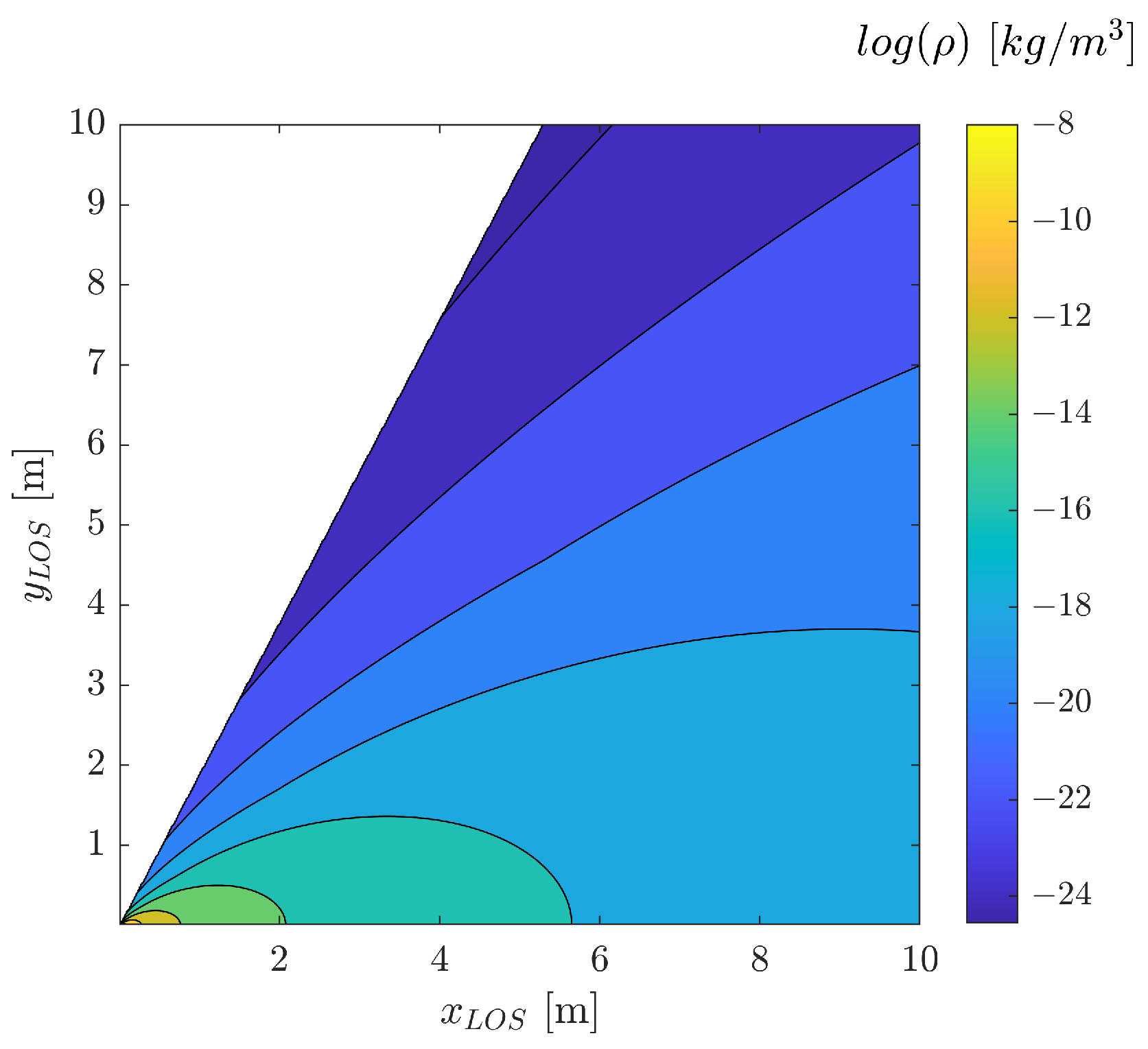
In the present work, the normal and tangential accommodation coefficients are considered, respectively, 1 and 0.97, as explained in [19], which assumes full thermal accommodation () and 97% of ambient gas molecules diffusely reflected by the surface (). Assuming a surface wall temperature of 300 K, the speed ratio results in 0.252. The list of parameters that define the thruster and the plume properties are reported in Table 1. Figure 1 shows the density field of the plume in the region in front of the nozzle for the parameters of Table 1.
The computation of the effects of the plume on the target is performed by defining a mesh of surfaces to represent the 3D shape of the target and evaluating the density field and surface force for each element at its centre. To this aim, the analytical description of the plume properties is particularly suited for the several model evaluations required to find plume total effect on the three dimensional body. The density field experienced by a example of a spacecraft shape from a 5 N hydrazine thruster is shown in Figure 2.
3. Plume Impingement Control Algorithm
The firing of the chaser’s thruster towards the target surfaces shall be defined to induce a momentum damping of the rotational motion of the target. The strategy here developed relies on the analytical model of the plume introduced in the previous section. Specifically, the algorithm is inspired by previous work in the literature, namely, references [19,21,23], where the thruster pointing towards the target and firing logic are determined by exploiting an onboard estimation of the plume torque on the target body. Assuming the target shape to be known, the surface locations can be obtained in function of the target’s pose estimation solution available and, thus, the effects of a specific pointing of the thruster can be analytically computed with the model of Equations (1) and (6). In this model, the occultation effects of the panels to the target’s body surfaces have been neglected for the sake of simplicity of the onboard computations of the plume torque. Moreover, as it can be noted from Figure 2, these occultation effects are mostly occurring when the thruster is pointing along the y-direction, which in any case will produce small surfaces torques in all the target’s body frame axes. The algorithm for contactless detumbling is structured in two layers addressing: (1) the pointing guidance of the chaser towards the target surfaces, and (2) the logic for thruster firing to induce the desired torque through the generated pressure field. Both pointing strategy and firing logic are dependent on the desired resulting torque that is required on the target body to induce a detumbling. This desired torque, referred here as guidance impingement torque, is defined in the Radial Transversal Normal (RTN) frame with a proportional law opposite to the target rotational angular momentum vector as follows:
where the superscript “L” stands for a torque vector expressed in the RTN frame, while the subscript “g” refers to the desired guidance torque. The vector is the target’s rotational angular momentum expressed in the RTN frame, and is a gain matrix that for our purposes is considered diagonal. The magnitude of the diagonal elements of the gain matrix are tuned according to the attainable torques with the considered plume at the operational distances. This guidance law will progressively reduce the magnitude of the rotational angular momentum vector, provided that the plume induced control is capable of achieving the guidance torques required.
In formulating the first layer of the algorithm, e.g., the chaser’s pointing strategy, some simplifications of the problem are necessary. Firstly, the plume is considered concentrated solely along the thrust centre line and the surface reflection is assumed to be only diffuse with a surface wall temperature of zero. This assumption results in a force interaction with the target surfaces that is directed only along the thruster Line of Sight (LOS) direction, again expressed in the RTN frame. According to the parameters and selected for the plume model and explained in Equation (6), the direction of force only slightly diverges from the thruster’s LOS, and thus this is considered an acceptable assumption for the purpose of algorithm definition. To define the pointing direction of the thruster LOS, here denoted as , a plane is considered orthogonal to the chaser–target vector direction and containing the target’s CoM. Within said plane, a firing line is identified which is orthogonal to the projection of the guidance torque on , denoted as in Figure 3.
where the represents the unit vector directed as the projection of the guidance torque vector on plane . Assuming that the force due to impingement is acting only in the direction of the thruster’s LOS, selecting a point on the firing line will induce a torque on the target aligned with the direction of . The specific point of firing is then selected by introducing a constant distance from the target Centre of Mass (COM), which is a scalar dependent on the specific target shape. Considering the target at a sufficiently large distance and the maximum pointing offset from the target COM is small, the angle between the computed attitude guidance direction and the chaser position vector results to be small. The pointing direction towards the target is obtained as follows:
The achievable torque with this pointing guidance is computed using the analytic plume model of Section 2 and compared with the guidance torque . The thruster is commanded ON if the torque stays within specified tolerances of direction and magnitude with respect to the desired guidance torque. An additional threshold is defined on the impingement torque absolute magnitude obtained with the onboard model, which helps to avoid unnecessary firing when the torque effects and commands are small. This logic allows for pointing guidance to be dictated solely by the position vector in RTN and the angular momentum vector of the target. The latter has a slow motion in the RTN frame, of frequency n, which allows for a reduced chattering with respect to a strategy that adaptively points to specific rotating surfaces. The orthogonality conditions between the chaser–target position vectors and the target’s rotational angular momentum are key for the efficiency of the impingement effects in the detumbling actions. The relations and design strategies of relative trajectories to ensure efficient detumbling operations will be detailed in the subsequent section. Moreover, the fixed predefined offset based on considerations on the target shape is useful to further reduce the sudden change of pointing to target-specific surface point along the firing line as performed in reference [19]. The algorithm proposed is similar to the one defined in [19], with the differences of smoothing pointing guidance provided by the constant computation of the pointing direction solely depending on the target angular momentum and chaser position not on the impingement effects (i.e., angles). A similar approach was also explored in the paper [21], where the command pointing is obtained assuming an equivalent resultant force to compute the hit point in the function of the desired torque, considering a V-bar approach. A different approach is taken in [23], where guidance and pointing are computed evaluating the impingement effect along different pointing candidates. In this way, the chaser is capable of adjusting its pointing within the control sample time to obtain the near-optimal pointing from the impingement efficiency point of view, without any prior assumption on the impingement force and using solely the impingement model. However, this operation is affected by a higher computational burden represented by the prediction of the tumbling state of the target at the next time and the evaluation of multiple impingement pointing torques. Moreover, the chaser attitude guidance will be less smooth than the option adopted in this work, so it will be more demanding to the chaser Attitude Determination and Control System (ADCS).
Figure 5 displays the block diagram of the impingement control algorithm. Apart from the algorithm setting for the impingement model and the impingement logic parameters, the following quantities are considered as inputs of the algorithm: (1) the target’s attitude state in terms of attitude matrix expressed with respect to inertial frame and the angular velocity vector in the body frame , (2) relative translational navigation in terms of relative position and relative velocity vectors expressed in the RTN frame. The unit vector expressed with refers to the real pointing direction in RTN of the impingement thruster, after the attitude control applied and described in Section 4.3. In the following section, the guidance and control strategies devised for the impingement operations are outlined. In this work, the modelling of the relative navigation solution is assumed as an input to the GC routines, affected by the noise and errors from a vision-based solution of pose estimation [34], reported in Section 5, where the simulation results are presented.
4. Chaser Guidance and Control Strategies
Impingement operations constitute a quite demanding phase for the chaser proximity GNC capabilities. The thruster used to induce the detumbling actions on the target surfaces is required to provide relatively frequent firings during operations, resulting in a large perturbation to the chaser’s relative motion. Therefore, careful formation keeping must be performed in conjunction with impingement firing to maintain the servicer close to the uncontrolled target. The design of the plume impingement scenario presents two main conflicting requirements, namely: safety of operations and impingement efficiency. In fact, to achieve a larger impingement actions and, thus, more effective detumbling of the target, the chaser is desired to be as close as possible, as evident from the inverse square dependence of plume density with distance in Equation (1). On the other hand, the safety of the relative motion during impingement firings will require maintaining a safe separation from the target to guarantee collision avoidance.
In this section, the design of the relative trajectory and attitude Guidance and Control (GC) strategies for impingement operations is presented, considering the coupling between the efficiency of impingement operations, trajectory safety and robustness.
4.1. Chaser Translational Guidance
In past studies performed by [19,21,23] a V-bar hovering strategy is employed to maintain the chaser in a stable relative position with respect to the target and perform perform impingement firings. Despite its simplicity, the latter approach lacks of key safety requirements due to the highly perturbed relative trajectory controlled during impingement operations. Particularly, passive abort safety during the V-bar approach is not granted given the absence one-orbit RN separation.
Let us consider the relative dynamics of the chaser and uncooperative target on a near-circular orbit expressed through the Relative Orbital Elements (ROE) parametrisation [35,36]:
where and are, respectively, the plant and input control matrix of relative motion considering Keplerian motion. The acceleration vector represents the total actions affecting on the relative motion in the RTN frame, while the u is the scalar mean argument of latitude of the target. The peculiarity of impingement operations lies in the variety of the contributions to the total acceleration vector acting on the formation.
The contribution represents the disturbance acceleration acting on the chaser resulting from the impingement firings towards the target. The quantity denotes instead the disturbance accelerations due to the plume effect on the target surfaces. Both contributions will affect the relative motion of the two objects, despite one acting directly on the chaser or on the target. The accelerations denoted as represent the control actions applied to the chaser platform to maintain the desired relative motion around the target. The contribution is typically known from the chaser firing time and impingement thrust line of sight (LOS) direction, except for firing control errors. On the other hand, the contribution on the target, , is affected by significant uncertainties. The models used for plume gas properties and surface interactions in space are simplified to an analytic model for the ease of impingement control algorithm development and implementation, but they entail large uncertainties compared to real effects in space. Consequently, the control response to achieve formation keeping, , is also influenced by these uncertainties, particularly in the trajectory evolution during failure scenarios.
Considerations on the effects of the plume actions uncertainties are therefore deemed crucial in the trajectory and operations design. Safe relative trajectory operations are often managed by carefully planning the trajectory to stay outside a Keep-Out-Zone (KOZ) and planning collision avoidance policies that force the chaser to move away from the target in case of any contingency. Another option is, the use of the passive abort safety, which is highly desired thanks to its capability to guarantee collision avoidance for a certain amount of time even in the cases of complete loss of control of the chaser platform [35,37]. Passive Relative Orbits (PRO) characterised by E/I vector separation can grant passive abort safety imposing a relative orbit geometry with minimum separation in the RN plane of the relative eccentricity and inclination vectors. Specifically, anti-parallel and parallel configurations of relative eccentricity and inclination vector result in an analytic solution for a non-vanishing minimum one-orbit separation between chaser and target in the RN plane.
A study on the improved safety of such trajectories with respect to failures is hereafter presented. Let us consider a failure scenario, where the safety is evaluated considering an initial error due to the uncertainties arising from the unmodelled impingement effects. The covariance change due to impingement related uncertainties is modelled considering an error source that behaves like an impulsive perturbation to the system, both in terms of magnitude and direction errors, according to the Gates model [38]:
where and are the instant before and after the impulsive impingement burn. The and are, respectively, the magnitude and pointing variance of the impingement action on the target, while the is the vector of impulsive impingement effect direction. The covariance evolution in a failure scenario, which models the propagation of the impingement model errors, is presented for two main test cases, namely: the V-bar hovering and a PSO orbit with E/I separation. The parameters of the errors propagation in the aforementioned test cases are reported in Table 2. In the values of thrust magnitude and direction errors, both are contributions of the perturbing acceleration during impingement on the target (due to the surface pressure) and on the servicer (due to control errors). Conservative values were chosen for the preliminary analysis in this section to encompass the various uncertain phenomenon involved in the impingement operations acting on the relative motion as impulsive effects.
Figure 6 and Figure 7 show the evolution of the covariance ellipse in RTN in the V-bar hovering case and in the PSO case, respectively. The KOZ in both cases is considered spherical with a radius of 8 m and centred on the target centre of mass. The magnitude and pointing uncertainties on the initial impulsive perturbation due to impingement are modelled as Gaussian distributions with 1, respectively, of 20% of the delta-v perturbation and 20 degrees of pointing direction error. A magnitude of delta-v perturbation of 1 mm/s was used in this analysis. The dynamics considered in the covariance propagation with the state transition matrix were limited to the Keplerian acceleration effects on the relative motion. The latter assumption was introduced in this preliminary analysis due to the limited propagation time evaluated, as well as the relatively high contribution of control-related action with respect to environmental disturbances. The future covariance ellipses represent the dispersion of the chaser position after a specific time in the presence of impingement effects uncertainties and uncontrolled flight. It is clear from Figure 6 how uncertainties in the impingement firing towards the target in the V-bar hovering case results in a quick violation of a target KOZ due to the majority of the impingement effects in the along-track direction. On the other hand, in the PSO case, a minimum separation in the RN plane is guaranteed thanks to the majority of effects of the covariance evolution under Keplerian dynamics in the along-track direction.
Both trajectory guidance options studied are almost bounded, hence stable, orbits in the assumption of relative Keplerian dynamics, hence not introducing additional unnecessary station keeping actions during operations. Nonetheless, based on the greater passive safety guaranteed the PSO option will be considered. A further assessment for the definition of the guidance orbits and trajectory guidance is the coupling of the impingement control algorithm with the relative position of the chaser and target.
According to the algorithm explained in Section 3, the chaser pointing and firing logic depends on two main factors: (1) the relative geometry and orientation of the chaser position vector concerning the target rotational angular momentum vector, and (2) the relative distance between the firing thruster and target’s surfaces. Assuming the target and chaser flying on a near-circular orbit, the inertially fixed rotational angular momentum vector of the target can be modelled in RTN with a precession motion of constant precession rate, which is equal to n orbital mean motion. An example of the characteristic precession motion of the vector in the RTN frame for a specific initial orientation is displayed in Figure 8. Considering the V-bar hovering case, the relative angle between the chaser position vector and vector depends mainly on the initial angle of the latter with respect to the normal direction and in time. Instead, in the PSO case the relative angle between the position vector and depends both on the chaser motion along the PSO orbit and on the angular momentum precession motion. Specifically, for any initial constant angle that the angular momentum vector has with the normal direction, namely, , a synchronised PSO is designed to maximise the orthogonality condition of the position vector and angular momentum vector in the region of closer flight to the target. At the first iteration, the trajectories with null relative semi-major axis and null relative mean argument of longitude are selected to ensure simultaneously null drift and same average inter-satellite distance during the path on the relative orbit. The geometry of the trajectory in RTN is then defined by the magnitude of relative eccentricity and inclination vectors and their phase. The magnitude of the vectors fixes the size of the elliptic motion of the chaser around the target. In this regard, is desirable for impingement operations the exploitation of smaller and closer relative orbits. The key aspect analysed in this work is the analysis of the phase of the relative eccentricity and inclination vectors. If we consider the E/I separation condition to ensure passive abort safety, only one of the two vector phases shall be defined, since the other will be derived from the (anti-)parallel condition. The choice of the relative phasing of relative eccentricity (or inclination vectors) is performed in this work considering the relative phasing with the precession motion of the rotational angular momentum of the target. Specifically for a particular motion of the target rotational angular momentum with phase , the desired phase of the relative eccentricity vector is defined as:
where is defined as the angle of the projection of the rotational angular momentum of the target on the RT plane with respect to the R axis at initial time. The “g” subscript stands for the guidance relative eccentricity vector phase. In this way, the relative eccentricity vector, defined as follows:
which guarantees two regions along the PSO where the rotational angular momentum and the relative position vector between the chaser and target are orthogonal. In the specific choice of relative phasing through the angle, , the regions where the rotational angular momentum vector and the chaser–target position vector are close to the orthogonality conditions is when the latter is mostly along the positive and negative radial direction R. This feature is beneficial to the operations since impingement disturbances acceleration due to impingement will be distributed mostly along the radial direction, which is half more effective in changing the relative trajectory with respect to the transversal effects. Moreover, this will benefit also the flight safety by inducing actions that create instantaneous separation in the along-track direction.
By designing such synchronised PSO to detumble the target, the efficiency of the firing in the thrusting regions is enhanced. It is therefore sufficient to estimate the rotational angular momentum vector initial motion with the initial pose determination algorithm to retrieve the operational relative PSO to be used as guidance for impingement operations. However, once the impingement operations begin, the plume effects will induce a change of the rotational angular momentum vector of the target in both magnitude and phase . This is due to how the impingement guidance is constructed to generate a torque in the P plane, and to both plume modelling and control errors, the latter related to the thresholds employed to rule the ON/OFF behaviour of the thruster (see Section 3). As a result, the phase of the rotational angular momentum will slightly change over the impingement firings. To cope with these situations where the orthogonality condition of the guidance orbit is degraded, a dynamic synchronisation strategy is implemented in this work. The concept of the strategy relies on the knowledge of the instantaneous phase of the vector from the servicer pose estimation and it implements a correction sequence when the said phase difference with the relative eccentricity vector exceeds a threshold value. The correction sequence will act on the phase of the relative eccentricity vector and bring it to the desired relative phasing of 90 degrees with respect to the current target angular momentum vector. The logic of the PSO synchronised adaptive guidance is depicted in the flow diagram of Figure 9. According to previous considerations, a guidance ROE state is defined considering null relative semi-major axis and relative mean longitude, magnitude of relative eccentricity and inclination vectors considering to the size of the relative orbit compliant with the distances required for effective impingement. The phase of relative eccentricity and inclination vectors are taken both equal to .
The synchronisation sequence that brings the servicer from the condition to the next guidance ROE is performed through impulsive burns. Specifically, a modification of the analytic manoeuvre definition method of reference [39] is employed. From the latter reference, the delta-v optimal in-plane and out-of-plane manoeuvres are placed at the the mean argument of latitude computed from the desired changes of the relative eccentricity and inclination vectors.
The minimum number of optimal manoeuvres for the in-plane to achieve a complete reconfiguration of the full ROE state is three. For the out-of-plane problem, it is one. The delta-v magnitudes are obtained considering the and and solving the following linear system:
In our specific case, the phase of the relative eccentricity and inclination vectors at the start/end of the transfer are equal thanks to the E/I separation conditions. Therefore, the optimal location of the in-plane and out-of-plane corrections coincide. Accordingly, it is convenient to split the out-of-plane burn into three manoeuvres, to occur simultaneously to the in-plane ones. Hence, a (anti-)parallel phasing of the relative eccentricity/inclination vectors is kept throughout the whole reconfiguration. A similar strategy is discussed in the design of transfers between inspection spiral trajectories in Borelli et al. [15]. The reconfiguration strategy adopted is thus performed with impulsive burns planned over a time span of two periods in this work. It is noteworthy that to retain the condition of optimality of in-plane re-configuration with three impulsive manoeuvres, the control time interval needs to be at least 1.5 periods [39]. The obtained manoeuvres are delta-v optimal, in the sense that they provide the minimum impulsive burn to reach a in-plane and out-of-plane reconfiguration provided that the total transfer time can be greater than 1.5 period, which is imposed in this work.
4.2. Chaser Translational Control
A feedback controller shall be defined to track the guidance trajectory in the PSO defined by to counteract external disturbances and unmodelled effects. Specifically for the impingement operation where the plume effects and frequent firing introduce a substantial perturbation, the controller shall be able to guarantee the required tracking of the guidance of the formation. Starting from the impingement control algorithm which defines the thruster firing, the control action on the chaser platform to counteract the disturbances on the formation is described by Equation (12). The perturbation resulting from the thruster firing on the chaser is cancelled out with an equal and opposite action with another thruster. Then the tracking of the guidance PSO will be achieved by cancelling the perturbation on the target and the model errors in thruster applications and pointing.
The controller defined to control this system is an Active Disturbance Rejection Controller (ADRC), which is designed to generate a stabilising system by using an Extended State Observer (ESO) to estimate the total disturbance. The concepts of ADRC are hereafter briefly described. Let us consider the relative motion dynamics expressed as second order system in function of Cartesian coordinates in the RTN frame:
where and are position and velocity vectors, respectively, and are the lower matrices of the CW dynamics, and indicates the errors and uncertainties in the system. Let us now consider the dynamics as an unknown function, forced also by the uncertainties and error term:
The key idea that lies behind the synthesis of a ADRC controller is to deal with the poor knowledge of the dynamics function through a variable augmentation of the system as follows:
where the term —referred to as total disturbance—is the contribution to be overcome with the controller, without the need to be expressively known. From Equation (20), an Extended State Observer (ESO) is constructed for the system as follows:
where the parameters are diagonal matrices which have in general different scalar values for the elements of the diagonal. For simplicity in this work the vector function is simply taken as linear function of , resulting in a substitution of in the dynamics of the ESO for both and . For the nonlinear definitions of the functions the reader is referred to reference [40]. Selecting the nonlinear functions as and will synthesise different controllers, which will exhibit particular behaviours. For example properties like overshoot or set-back time will change in relation to the nonlinear function selected and systems on which are applied. The proposed ESO will be used to estimate the augmented plant states with the variables .
The controller to track the reference , obtained with defined by the guidance scheme of Section 4.1, can then be defined considering a stabilising feedback as follows:
where and are constant diagonal gain matrices. It is noteworthy that this definition relies on linear control functions, but the ADRC methods can exploit different nonlinear functions in the definition of , providing controller with different behaviours. The proposed control law of Equation (22), coupled with the ESO, is in the form , which reduces Equation (19) to a cascade integral form [40]. Therefore, the control can be trivially defined as a function of the error and derivative of the error of the state with respect to the reference in order to stabilise the system. This formulation of ADRC is used in this work to track the PSO guidance during impingement operations. The parameters used in the controller synthesised for this purpose are reported in Table 3.
4.3. Attitude Guidance and Control
The attitude control system of the chaser is in charge of acquiring the pointing guidance retrieved from the impingement control algorithm logic. Specifically, a tracking guidance is defined imposing the pointing of the thruster LOS along vector in the RTN frame retrieved from the impingement control function. The attitude matrix expressed with respect to the RTN frame used as guidance command to the ADCS is reported as follows:
where the unit vector is defined in function of the trajectory guidance used. For the PSO fly-around guidance, is taken as , where and are the relative position and velocity unit vectors in the RTN frame. For the V-bar hovering case the unit vector is taken simply as the normal direction of the RTN frame. Note that the present definition of the attitude matrix depends on the vector, defined in Equation (10), and on the variation of position and velocity vectors along the relative trajectory. In the passively safe relative orbit defined, the variation of this pointing direction is with frequency of the mean motion n, which ensures a smooth attitude guidance to follow and avoids chattering behaviour. A quaternion feedback law is defined to track the desired attitude during impingement operations:
where and are, respectively, the vector component and the scalar component of the error quaternion, the vector is the angular velocity error computed from the commanded rates, and and are constant gain values.
In the control implementation, reaction wheels are used. The actuators’ dynamics are implemented considering only a maximum torque attainable of 0.4 Nm. The inclusion of desaturation phases is neglected in this work and is only checked as a posteriori checks in the actuator response.
5. Simulation Results
The impingement strategy developed within this work and described in the previous section is validated through a simulation campaign. The simulation tool is implemented in a MATLAB/Simulink environment. The attitude dynamics of the chaser and target are simulated, together with the relative motion dynamics. The test case selected is the detumbling with plume impingement of a large constellation satellite that failed in orbit and experiencing large tumbling rates. In this example, the platform geometry of a OneWeb satellite is taken [15]. The orbital parameters of the large constellation satellite are shown in Table 4. Perturbations to the relative motion, i.e., Earth oblateness and differential drag, are not included in the simulation due to the orbital region of the test case. However, the strategy described in the previous section is applicable to a scenario where also perturbations to the relative motion become relevant, thanks to the logic of counteracting the total disturbances in the translational control outlined in the previous section. The perturbation effects will only reflect on the station keeping costs required during impingement operations. The physical properties of the servicer and the target are reported in Table 5. The thruster employed for plume impingement is a 5 N thruster with the properties outlined in Table 1.
Table 6 shows the parameters that define the behaviour of the impingement control algorithm described in Section 3 and used in the test case simulations. The parameters for guidance and control of translational and rotational dynamics of the chaser are listed in Table 6. In addition to the parameters described in the previous section, to tune the behaviour of the impingement control logic, additional parameters have been introduced. A detumbling limit is set to stop the simulation if the target’s angular rate magnitude falls below that threshold thus the object is considered as detumbled. A maximum distance is set to avoid firing from far away, while a threshold on the pointing acquired by the servicer is set in order to turn off the impingement firing when it is performing large slews and the current attitude is far from the commanded one. Table 7 reports additional parameters considered in the simulations, comprehending the errors arising from the pose estimation onboard and from the real effect of the plume with respect to the modelled one. Both error sources are defined considering an additive noise on the real values with a Gaussian distribution.
Clearly, the performance of the impingement control algorithm and of the overall servicer’s operations strongly depend on the initial conditions. In fact, different attitude states and the initial orientation of the rotational angular momentum vector of the target will lead to very different achievable effects with the pressure field from the thruster. A simulation campaign was performed for the three initial angular rates reported in Table 8, each simulating 50 different initial conditions of attitude orientation. Moreover, every test case was simulated in three different conditions of GC approach: (1) V-bar hovering of the servicer, (2) PSO approach with no adaptive synchronisation guidance, and (3) PSO with adaptive synchronisation guidance. The comprehensive results of the simulations campaign are reported in Table 8. The results are shown in terms of mean and standard deviation of the total delta-v required for impingement operations, and the number of simulations where the servicer has not been able to detumble the spacecraft in the maximum simulation time, e.g., 30 orbital periods. The first clear behaviour is the large difference in total delta-v cost of operations between the cases with different initial angular rates expressed in the target body frame. This was expected and it is the manifestation of the different torques achievable along different target body frame directions due to its shape and symmetry and to the use of pressure forces on its surfaces. An initial angular rate along the y-axis of the target’s body frame results in the hardest one to detumble, as the symmetry of the target is not advantageous to obtain torques in that direction with the impingement plume; see Figure 2.

Table 5.
Servicer and target parameters for the test case simulated.
| Chaser Spacecraft | ||
|---|---|---|
| Mass | 600 kg | |
| Inertia | diag([200, 100, 200]) | |
| Initial angular rate | [0, 0, 0] deg/s | |
| Target spacecraft | ||
| Mass | 150 kg | |
| Inertia | diag([45, 25, 50]) | |
| Initial angular rate | See Table 8 | |
| Shape (see Figure 2) | - | Box m Panels m |
Table 6.
Impingement control parameters and guidance and control functions parameters for the simulated test case.
Table 6.
Impingement control parameters and guidance and control functions parameters for the simulated test case.
| Impingement Control | ||
|---|---|---|
| Impingement offset | 1.25 m or 0.3 m | |
| Angle tolerance | 45 deg | |
| Magnitude tolerance | Nm | |
| Gain of guidance torque | ||
| Detumbling limit | 0.05 deg/s | |
| Limit pointing chaser | 5.7 deg | |
| Distance limit firing | 16 m | |
| Translational guidance | ||
| Phase angle limit | 15 deg | |
| Synch switch limit | 0.5 deg/s | |
| KOZ radius | 8 m | |
| V-bar initial condition | [0, 14, 0, 0, 0, 0]T m | |
| PSO initial condition | [0, 0, 0, 12, 0, 12]T m | |
| Translational control | ||
| ADRC ESO parameter 1 | 5 | |
| ADRC ESO parameter 1 | 200 | |
| ADRC ESO parameter 1 | 0.1 | |
| ADRC controller gain 1 | 0.01 | |
| ADRC controller gain 2 | 1 | |
| ADRC controller parameter | 1 | |
| PD controller gain 1 | 0.12 | |
| PD controller gain 2 | 1.2 | |
| Rotational control | ||
| Attitude controller gain 1 | 1 | |
| Attitude controller gain 2 | 10 | |
| Maximum torque RWs | 0.4 Nm | |
Table 7.
Additional simulation parameters considered in the impingement test case.
| Numerical propagator | Fixed step Runge–Kutta 4th order |
| Simulation step | 0.2 s |
| Max simulation time | 30 periods |
| Absolute attitude errors | 2 deg (1) |
| Angular velocity errors | 0.05 deg/s (1) |
| Magnitude error impingement torque | 50% (1) |
| Pointing error impingement torque | 20 deg (1) |
Table 8.
Simulation results.
| 0,tgt = [8, 1, 1] [deg/s] | |||
|---|---|---|---|
| [m/s] | [m/s] | ||
| V-bar hovering | 17.04 | 1.82 | 0 |
| ROE no sync | 13.17 | 1.35 | 32 |
| ROE sync | 13.48 | 1.31 | 0 |
| 0,tgt = [1, 8, 1] [deg/s] | |||
| [m/s] | [m/s] | ||
| V-bar hovering | 39.07 | 0.89 | 0 |
| ROE no sync | 32.75 | 0.76 | 6 |
| ROE sync | 32.59 | 0.76 | 0 |
| 0,tgt = [1, 1, 8] [deg/s] | |||
| [m/s] | [m/s] | ||
| V-bar hovering | 9.94 | 1.16 | 0 |
| ROE no sync | 9.76 | 1.07 | 29 |
| ROE sync | 9.67 | 0.94 | 0 |
Simulations of the V-bar hovering operations, a method usually exploited in the literature, show satisfactory results in detumbling the target in all three cases of initial angular rate. However, the cost of delta-v was observed to be larger than the ones using the PSO guidance for operations. This behaviour is generally due to the fact that in PSO cases, there are some conditions where the servicer is closer to the target with respect to the V-bar defined distance. Moreover, the V-bar hovering option does not guarantee a satisfactory level of safety in terms of collision avoidance in failure scenarios. It is noteworthy that in the V-bar hovering case, detumbling happens in a shorter time frame. This behaviour can be noted from Figure 10, Figure 11 and Figure 12, where the time evolution of the angular rate magnitude of all simulation cases is displayed, together with the distribution of total delta-v spent for operations. The latter figures show the 50 simulations performed for the initial angular rate condition of deg/s.
The simulations on PSO trajectories show a peculiar behaviour. The runs of the PSO case without synchronisation show the servicer incapable of detumbling the target within the limit of 30 periods, clearly visible from Figure 11.
This happens when the target rotational angular momentum is driven to a direction where the conditions to apply the impingement control logic are no longer satisfied. To ensure that the impingement control is effective, the servicer along its relative trajectory around the target shall guarantee situations where the thruster LOS is orthogonal to the target’s angular momentum vector . If this happens, the attainable control torque to achieve the angular momentum decrease with the impingement surface effects is maximised. Due to the motion of the target’s angular momentum vector , shown in Figure 8, coupled with the relative trajectory motion, the system may reach conditions that do not allow these peculiar orthogonality conditions between the relative position vector and the vector along the PSO, according to the threshold of set in the impingement firing logic. If so, the impingement control does not command a firing towards the target due to the poor effects achievable, and the detumbling operations are not successful and reach a stationary limit. This behaviour is successfully resolved in the simulations where the adaptive synchronisation along the PSO orbit is performed by the servicer. Here, when the misalignment between the PSO and the motions reaches a certain threshold, the guidance block takes care of stopping the impingement operations and autonomously plans a correction sequence to reach the desired condition. The benefits of the adaptive translational guidance logic are supported by the results displayed in Table 8, where the “ROE sync” rows present no cases that failed the detumbling (i.e., ).
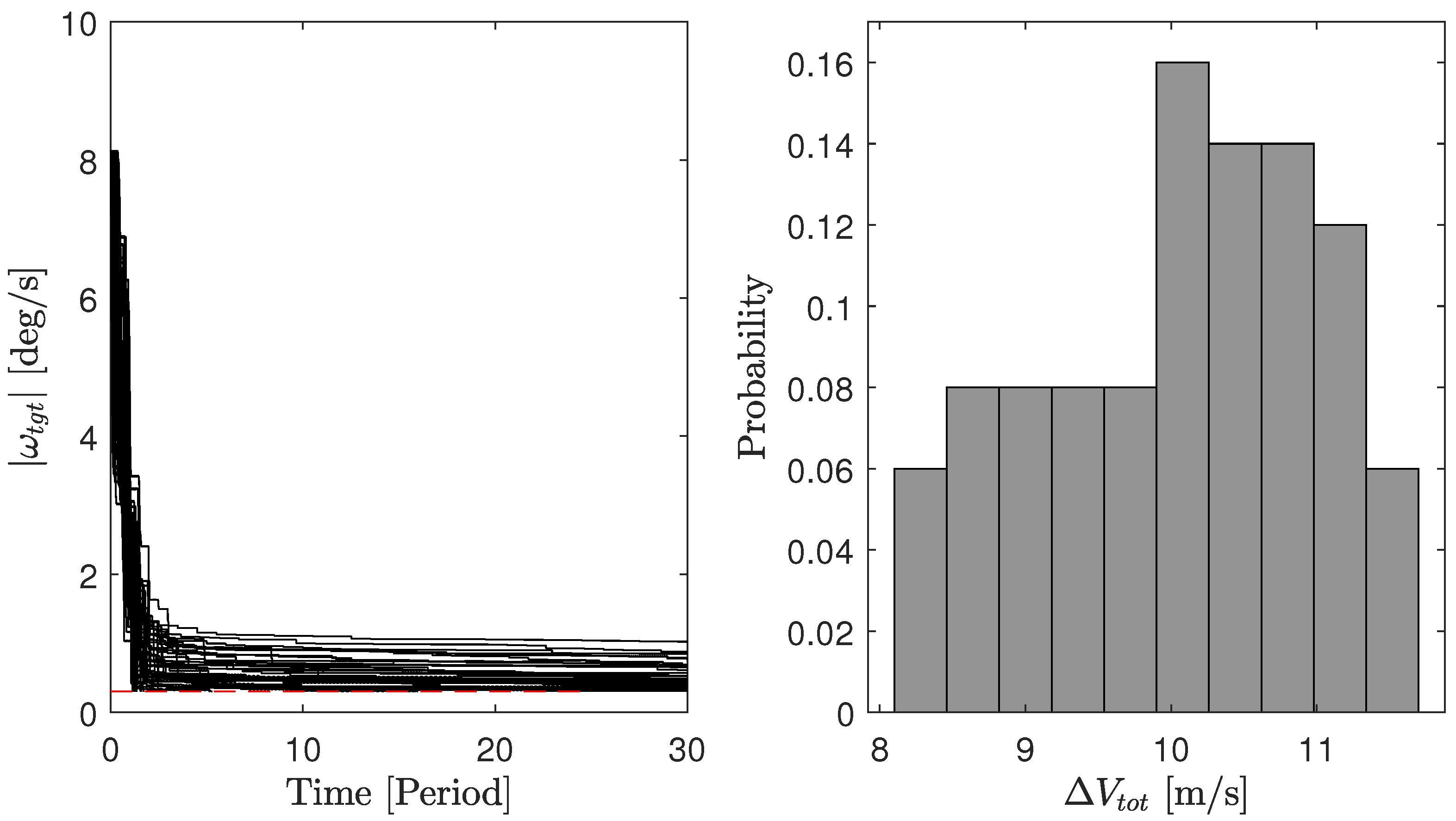
The cases with the adaptive synchronisation PSO guidance essentially reach the same level of successful detumbling using an approximately equal amount of delta-v concerning the V-bar hovering cases, but ensure a higher level of safety of operations. It is worth remarking that the delta-v reported in Table 8 and in Figure 12 refer to the delta-v spent for the impingement operations, without accounting for the synchronisation burns cost performed over the two periods and triggered by the adaptive synchronisation guidance. Nonetheless, the cost for compensation of a difference in phase between two consecutive guidance ROE states of 15 degrees, considered as threshold for the triggering of the synchronisation sequence as reported in Table 6, results in only 7 mm/s. Considering that on average two synchronisation sequences are triggered in the simulation performed, their delta-v contribution is neglected. The crucial improvements in terms of operational safety come at the cost of a longer duration of the detumbling phase. Nevertheless, the detumbling time stays within 30 orbital periods, i.e., around 2 days, which is operationally feasible for proximity operations within an IOS and ADR mission. It can be noted that only one simulation in Figure 12 reached the detumbled state with angular rate below 0.05 deg/s in a time greater than 30 orbital periods.
Figure 13 shows the trajectories used during the operations employing the adaptive synchronisation PSO guidance for an example simulation. In black, the reference impingement PSO is shown, where clearly the geometry remains unchanged since only the phase is adaptively controlled by the guidance block. In blue, the trajectories used for the synchronisation correction sequence are displayed, while green markers show the firing points of impingement towards the target. The evolution of the angular velocity vector components is displayed in Figure 14, where grey regions represent the synchronisation sequence intervals of time. An example of a transfer sequence is represented in Figure 15, where on the right the path in the ROE space of the relative eccentricity and inclination vectors are shown and on the left the projection of the passively safe trajectory in the RN plane. Thanks to the designed optimal impulsive manoeuvres scheme, the relative eccentricity and relative inclination vectors are controlled simultaneously and remain equal during the transfer, as it can be noted from Figure 15. This ensures the E/I separation concept to be satisfied during the whole transfer sequence, and thus ensuring passive safety during the transfer [35]. In the plot in the right-hand portion of Figure 15, the one-orbit minimum distance in the RN plane arising from the E/I separation condition is displayed.
A comparison of the tracking controller for the chaser translational control problem is performed, where the performances of ADRC and PD control are simulated with the parameters reported in Table 6. Note that this comparison is performed accounting for the first impingement operation part of the simulation shown in Figure 14, before the synchronisation correction sequence. As seen in Figure 16, both controllers successfully tracked the PSO trajectory defined by the guidance block. Nonetheless, the delta-v spent with the ADRC controller is slightly less, as displayed in Figure 17. An example of the total disturbance registered in the ADRC controller along the example simulation, based on Equation (20), is shown in Figure 18.
6. Conclusions
Capabilities to control rotational motion are crucial for the robustness, safety and success of proximity operations to uncooperative and non-collaborative targets during servicing and removal missions. This paper presented the development and design of a plume impingement strategy that leverages the onboard thrusters of the servicer to induce a detumbling torque on a fast-rotating target to ease the final approach and capture operations. Indeed, this strategy holds the advantage of not requiring any contact with the target and the use of the onboard thrusters already available in the servicer platform. This paper presented a novel approach to designing the guidance and control of the operations where the passive abort safety conditions are guaranteed to cope with complex and demanding failure scenarios. At the same time, an adaptive trajectory guidance scheme is implemented to maintain the impingement control efficiency throughout the passively safe trajectory. The methods proved to be as efficient as a V-bar hovering, previously employed in the literature, but with evident and considerable improvement in the safety of operations. Monte Carlo simulation results demonstrated the efficiency of detumbling a small-class two-panel spacecraft with tumbling rates up to 11 deg/s distributed in any body axes.
Future endeavours will focus on addressing the limitations of the proposed strategy and the presented results. Specifically, the simulations performed model the relative navigation solution indirectly, introducing errors in the required state estimate. An improved study on the effectiveness of the strategy in a real-time scenario will be conducted, modelling the pose estimation and navigation routines for both the chaser and the uncooperative target. Furthermore, the present paper is limited to studying the effectiveness of plume impingement on a small-class spacecraft with two panels. A more comprehensive evaluation of the behaviour with targets of different shapes and sizes is therefore envisioned to showcase the robustness of this approach to any in-orbit debris objects.
Author Contributions
Conceptualization, G.B., G.G. and C.C.; methodology, G.B.; software, G.B.; validation, G.B. and G.G.; formal analysis, G.B.; investigation, G.B; resources, G.G. and C.C.; writing—original draft preparation, G.B.; writing—review and editing, G.B., G.G. and C.C.; visualization, G.B; supervision, G.G. and C.C.; project administration, G.G. and C.C.; funding acquisition, G.G. and C.C.; All authors have read and agreed to the published version of the manuscript.
Funding
The research leading to these results has received funding from the European Research Council (ERC) under the European Union’s Horizon 2020 research and innovation programme as part of project COMPASS (Grant agreement No 679086), https://www.compass.polimi.it/ (accessed on 12/03/2024). The contribution of Dr. Gabriella Gaias is funded by the European Union’s Horizon 2020 research and innovation programme under the Marie-Sklodowoska Curie grant ReMoVE (grant agreement nr 793361).
Data Availability Statement
The raw data supporting the conclusions of this article will be made available by the authors on request.
Conflicts of Interest
The authors declare no conflicts of interest.
References
- Liou, J.C.; Johnson, N.L. A sensitivity study of the effectiveness of active debris removal in LEO. Acta Astronaut. 2009, 64, 236–243. [Google Scholar] [CrossRef]
- Biesbroek, R.; Aziz, S.; Wolahan, A.; Cipolla, S.F.; Richard-Noca, M.; Piguet, L. The clearspace-1 mission: ESA and clearspace team up to remove debris. In Proceedings of the 8th European Conference on Space Debris, Darmstadt, Germany, 20–23 April 2021. [Google Scholar]
- Jaekel, S.; Lampariello, R.; Rackl, W.; De Stefano, M.; Oumer, N.; Giordano, A.M.; Porges, O.; Pietras, M.; Brunner, B.; Ratti, J.; et al. Design and Operational Elements of the Robotic Subsystem for the e.deorbit Debris Removal Mission. Front. Robot. AI 2018, 5, 100. [Google Scholar] [CrossRef]
- Forshaw, J.L.; Aglietti, G.S.; Navarathinam, N.; Kadhem, H.; Salmon, T.; Pisseloup, A.; Joffre, E.; Chabot, T.; Retat, I.; Axthelm, R.; et al. RemoveDEBRIS: An in-orbit active debris removal demonstration mission. Acta Astronaut. 2016, 127, 448–463. [Google Scholar] [CrossRef]
- Bombardelli, C.; Pelaez, J. Ion Beam Shepherd for Contactless Space Debris Removal. J. Guid. Control. Dyn. 2011, 34, 916–920. [Google Scholar] [CrossRef]
- Tsuno, K.; Wada, S.; Ogawa, T.; Saito, N.; Fukushima, T.; Ebisuzaki, T.; Nakamura, Y.; Sasoh, A. Laser ablation induced impulse study for removal of space debris mission using small satellite. Appl. Phys. A 2022, 128, 932. [Google Scholar] [CrossRef]
- Schaub, H.; Sternosvky, Z. Active Space Debris Charging for Contactless Electrostatic Disposal Maneuvers. In Proceedings of the 6th European Conference on Space Debris, Darmstadt, Germany, 22–25 April 2013. [Google Scholar]
- Silha, J.; Pittet, J.N.; Hamara, M.; Schildknecht, T. Apparent rotation properties of space debris extracted from photometric measurements. Adv. Space Res. 2018, 61, 844–861. [Google Scholar] [CrossRef]
- Kucharski, D.; Kirchner, G.; Koidl, F.; Fan, C.; Carman, R.; Moore, C.; Dmytrotsa, A.; Ploner, M.; Bianco, G.; Medvedskij, M.; et al. Attitude and spin period of space debris envisat measured by satellite laser ranging. IEEE Trans. Geosci. Remote Sens. 2014, 52, 7651–7657. [Google Scholar] [CrossRef]
- Lemmens, S.; Krag, H.; Rosebrock, J.; Carnelli, I. Radar mappings for attitude analysis of objects in orbit. In Proceedings of the 6th European Conference on Space Debris, Darmstadt, Germany, 22–25 April 2013; pp. 20–24. [Google Scholar]
- Yamamoto, T.; Matsumoto, J.; Okamoto, H.; Yoshida, R.; Hoshino, C.; Yamanaka, K. Pave the way for active debris removal realization: Jaxa commercial removal of debris demonstration (crd2). In Proceedings of the 8th European Conference on Space Debris, Darmstadt, Germany, 20–23 April 2021; p. 200. [Google Scholar]
- Team, E.C. e. Inspector CDF Study Report—Assessment of an ENVISAT Imaging Mission as a Precursor to a Potential ENVISAT Deorbit; Technical Report; European Space Agency (ESA): Paris, Frence, 2017. [Google Scholar]
- Silvestrini, S.; Prinetto, J.; Zanotti, G.; Lavagna, M. Design of robust passively safe relative trajectories for uncooperative debris imaging in preparation to removal. In Proceedings of the 2020 AAS/AIAA Astrodynamics Specialist Conference, South Lake Tahoe, CA, USA, 9–13 August 2020; Volume 175, pp. 4205–4222. [Google Scholar]
- Colombo, C.; Huang, S.; Borelli, G.; Cavenago, F.; Nugnes, M.; Gonzalo Gòmez, J.; Gaias, G.; Massari, M.; Vallini, L.; Petit, M.; et al. Mission analysis and design for an active debris removal service for large constellations. In Proceedings of the 8th European Conference on Space Debris, ESA/ESOC, Darmstadt, Germany, 20–23 April 2021. [Google Scholar]
- Borelli, G.; Gaias, G.; Colombo, C. Rendezvous and proximity operations design of an active debris removal service to a large constellation fleet. Acta Astronaut. 2023, 205, 33–46. [Google Scholar] [CrossRef]
- Cheng, W.; Li, Z.; He, Y. Strategy and Control for Robotic Detumbling of Space Debris by Using Flexible Brush. In Proceedings of the 2019 3rd International Conference on Robotics and Automation Sciences (ICRAS), Wuhan, China, 1–3 June 2019; pp. 41–47. [Google Scholar]
- Liu, Y.Q.; Yu, Z.W.; Liu, X.F.; Cai, G.P. Active detumbling technology for high dynamic non-cooperative space targets. Multibody Syst. Dyn. 2019, 47, 21–41. [Google Scholar] [CrossRef]
- Wang, X.; Zhou, Z.; Chen, Y.; Chen, S. Optimal contact control for space debris detumbling and nutation damping. Adv. Space Res. 2020, 66, 951–962. [Google Scholar] [CrossRef]
- Peters, T.V.; Escorial Olmos, D. COBRA contactless detumbling. CEAS Space J. 2016, 8, 143–165. [Google Scholar] [CrossRef]
- Ferrari, F.; Benvenuto, R.; Lavagna, M. Gas plume impingement technique for space debris de-tumbling. In Proceedings of the 9th International ESA Conference on Guidance, Navigation and Control Systems, Porto, Portugal, 2–6 June 2014. [Google Scholar]
- Nakajima, Y.; Tani, H.; Yamamoto, T.; Murakami, N.; Mitani, S.; Yamanaka, K. Contactless Space Debris Detumbling: A Database Approach Based on Computational Fluid Dynamics. J. Guid. Control. Dyn. 2018, 41, 1906–1918. [Google Scholar] [CrossRef]
- Nakajima, Y.; Mitani, S.; Tani, H.; Murakami, N.; Yamamoto, T.; Yamanaka, K. Detumbling Space Debris via Thruster Plume Impingement. In Proceedings of the AIAA/AAS Astrodynamics Specialist Conference, Long Beach, CA, USA, 13–16 September 2016. [Google Scholar] [CrossRef]
- Borelli, G.; Gaias, G.; Colombo, C. Rotational Control with Plume Impingement to Aid the Rigid Capture of an Uncooperative Failed Satellite. Adv. Astronaut. Sci. 2021, 175, 4085–4104. [Google Scholar]
- Bennett, T.; Stevenson, D.; Hogan, E.; Schaub, H. Prospects and challenges of touchless electrostatic detumbling of small bodies. Adv. Space Res. 2015, 56, 557–568. [Google Scholar] [CrossRef]
- Bennett, T.; Schaub, H. Contactless electrostatic detumbling of axi-symmetric GEO objects with nominal pushing or pulling. Adv. Space Res. 2018, 62, 2977–2987. [Google Scholar] [CrossRef]
- Bennet, T.; Schaub, H. Touchless Electrostatic DEtumble of a Representative Box-and-Panel Spacecraft Configuration. In Proceedings of the 7th European Conference on Space Debris, Darmstadt, Germany, 18–21 April 2017. [Google Scholar]
- Ortiz, N.; Walker, S.; Jankovic, M.; Romero Martin, J.M.; Kirchner, F.; Vasile, M. Control analysis for a contactless de-tumbling method based on eddy currents: Problem definition and approximate proposed solutions. In Proceedings of the AIAA Guidance, Navigation, and Control Conference, Boston, MA, USA, 6–8 July 2016. [Google Scholar] [CrossRef]
- Kumar, R.; Sedwick, R.J. Despinning Orbital Debris Before Docking Using Laser Ablation. J. Spacecr. Rocket. 2015, 52, 1129–1134. [Google Scholar] [CrossRef]
- Vetrisano, M.; Thiry, N.; Vasile, M. Detumbling large space debris via laser ablation. In Proceedings of the IEEE Aerospace Conference Proceedings, Big Sky, MT, USA, 7–14 March 2015; Volume 2015. [Google Scholar] [CrossRef]
- Benoit, A.; Ribeiro, A.; Soares, T.; Van den Broeck, M. Passive magnetic detumbling to enable Active Debris Removal of non-operational satellites in Low Earth Orbit. CEAS Space J. 2021, 13, 599–636. [Google Scholar] [CrossRef]
- Simons, G.A. Effect of nozzle boundary layers on rocket exhaust plumes. AIAA J. 1972, 10, 1534–1535. [Google Scholar] [CrossRef]
- Boyd, I.D. Modelling of Satellite Control Thruster Plumes. Ph.D. Thesis, University of Southampton, Southampton, UK, 1988. [Google Scholar]
- Moe, K.; Moe, M.M. Gas–surface interactions and satellite drag coefficients. Planet. Space Sci. 2005, 53, 793–801. [Google Scholar] [CrossRef]
- Gaias, G.; Lovera, M. Extended Kalman filters for close-range navigation to noncooperative targets. Adv. Space Res. 2023, in press. [CrossRef]
- D’Amico, S.; Montenbruck, O. Proximity Operations of Formation-Flying Spacecraft Using an Eccentricity/Inclination Vector Separation. J. Guid. Control. Dyn. 2006, 29, 554–563. [Google Scholar] [CrossRef]
- Gaias, G.; Lovera, M. Trajectory Design for Proximity Operations: The Relative Orbital Elements’ Perspective. J. Guid. Control. Dyn. 2021, 44, 2294–2302. [Google Scholar] [CrossRef]
- Gaias, G.; Ardaens, J.S. Flight Demonstration of Autonomous Noncooperative Rendezvous in Low Earth Orbit. J. Guid. Control. Dyn. 2018, 41, 1337–1354. [Google Scholar] [CrossRef]
- Gates, C.R. A Simplified Model of Midcourse Maneuver Execution Errors; Technical Report; NASA: Greenbelt, MD, USA, 1963. [Google Scholar]
- Gaias, G.; D’Amico, S. Impulsive Maneuvers for Formation Reconfiguration Using Relative Orbital Elements. J. Guid. Control. Dyn. 2015, 38, 1036–1049. [Google Scholar] [CrossRef]
- Han, J. From PID to Active Disturbance Rejection Control. IEEE Trans. Ind. Electron. 2009, 56, 900–906. [Google Scholar] [CrossRef]
Figure 1.
Density field of the plume obtained with the Simons model with the parameters of hydrazine shown in Table 1. The reference frame adopted features along the centre line of the thruster.
Figure 1.
Density field of the plume obtained with the Simons model with the parameters of hydrazine shown in Table 1. The reference frame adopted features along the centre line of the thruster.

Figure 2.
Density field on an example target represented by meshed surfaces. In magenta the thruster centre line pointing is displayed. A 5 N hydrazine thruster is considered.
Figure 2.
Density field on an example target represented by meshed surfaces. In magenta the thruster centre line pointing is displayed. A 5 N hydrazine thruster is considered.

Figure 3.
Plume impingement problem geometry exploited in the pointing algorithm definition. All vector quantities are expressed in the RTN frame, a color-code (orange) is used to highlight quantities belonging to the plane .
Figure 3.
Plume impingement problem geometry exploited in the pointing algorithm definition. All vector quantities are expressed in the RTN frame, a color-code (orange) is used to highlight quantities belonging to the plane .

Figure 4.
Plume impingement problem guidance torques, achieved torque with the plume analytic model and threshold included in the algorithm.
Figure 4.
Plume impingement problem guidance torques, achieved torque with the plume analytic model and threshold included in the algorithm.

Figure 5.
Flowchart of the impingement control algorithm.

Figure 6.
Representation of the covariance 1 ellipsoids evolution at three different fractions of the orbital period T after the error propagation in the V-bar hovering case, with the parameters detailed in Table 2.
Figure 6.
Representation of the covariance 1 ellipsoids evolution at three different fractions of the orbital period T after the error propagation in the V-bar hovering case, with the parameters detailed in Table 2.

Figure 7.
Representation of the covariance ellipsoid evolution at three different fractions of the orbital period T after the error propagation in the PSO case, with the parameters detailed in Table 2. (a) 3D view in RTN, (b) view in the RN plane.
Figure 7.
Representation of the covariance ellipsoid evolution at three different fractions of the orbital period T after the error propagation in the PSO case, with the parameters detailed in Table 2. (a) 3D view in RTN, (b) view in the RN plane.

Figure 8.
Example of target rotation angular momentum vector direction motion in RTN for one orbital period.
Figure 8.
Example of target rotation angular momentum vector direction motion in RTN for one orbital period.

Figure 9.
PSO synchronised adaptive guidance block diagram.

Figure 10.
Simulations results of the V-bar hovering case for impingement operations considering the initial angular rate of deg/s and 50 different initial attitude states. On the left, the time history of the target’s angular rate magnitude is shown for all runs. The right side shows the distribution of the total delta-v spent for the impingement operations in the simulations displayed.

Figure 11.
Simulation results of the PSO guidance case for impingement operations considering the initial angular rate of deg/s and 50 different initial attitude. On the left, the time history of the target’s angular rate magnitude is shown for all runs. The right side shows the distribution of the total delta-v spent for the impingement operations in the simulations displayed.

Figure 12.
Results of the adaptive synchronisation PSO guidance solution considering the initial angular rate of deg/s and 50 different initial attitude. On the left, the time history of the target’s angular rate magnitude is shown for all runs. The right side shows the distribution of the total delta-v spent for the impingement operations in the simulations displayed.

Figure 13.
Example trajectories of impingement operations during the adaptive synchronisation PSO guidance cases.
Figure 13.
Example trajectories of impingement operations during the adaptive synchronisation PSO guidance cases.

Figure 14.
Evolution of the target angular velocity components in the body frame during the impingement operations with adaptive synchronisation PSO guidance and initial conditions of deg/s.
Figure 14.
Evolution of the target angular velocity components in the body frame during the impingement operations with adaptive synchronisation PSO guidance and initial conditions of deg/s.

Figure 15.
(Left) Representation of the relative eccentricity and relative inclination vector during transfers due to impulsive manoeuvres. (Right) Projection in the RN plane of the failure trajectories during transfer, showing an effective E/I separation to ensure passive safety [35]. The red dashed line represents the KOZ limit considered.

Figure 16.
Evolution of ROEs during the impingement operations with adaptive synchronisation PSO guidance and initial conditions of deg/s. Simulations obtained with the ADRC and PD controller are shown.
Figure 16.
Evolution of ROEs during the impingement operations with adaptive synchronisation PSO guidance and initial conditions of deg/s. Simulations obtained with the ADRC and PD controller are shown.

Figure 17.
Evolution of delta-v spent over time during the impingement operations (top) and percentage of saving of ADRC vs PD (bottom) with adaptive synchronisation PSO guidance and initial conditions of deg/s. Simulations obtained with the ADRC and PD controller are shown.
Figure 17.
Evolution of delta-v spent over time during the impingement operations (top) and percentage of saving of ADRC vs PD (bottom) with adaptive synchronisation PSO guidance and initial conditions of deg/s. Simulations obtained with the ADRC and PD controller are shown.

Figure 18.
Evolution of the integral of the total disturbance vector components along RTN frame used in the ADRC controller to track the guidance trajectory.
Figure 18.
Evolution of the integral of the total disturbance vector components along RTN frame used in the ADRC controller to track the guidance trajectory.

Table 1.
Thruster and flow parameters for the 5 N Hydrazine thruster considered in this study.
| Parameter | Symbol | Value |
|---|---|---|
| Thrust | F | 5 N |
| Specific Impulse | 220 s | |
| Expansion ratio (area) | 80 | |
| Chamber temperature | 1000 K | |
| Chamber pressure | 1.1 MPa | |
| Specific heat ratio | 1.37 | |
| Specific gas constant | 791.85 | |
| Boundary layer ratio | 0.01 | |
| Nozzle aperture angle | 15 deg | |
| Normal accommodation coeff. | 1 | |
| Tangential accommodation coeff. | 0.97 | |
| Limiting wall temperature | 300 K |
Table 2.
Conditions and parameters for the error propagation analysis of a failure scenario during impingement operations.
Table 2.
Conditions and parameters for the error propagation analysis of a failure scenario during impingement operations.
| Initial condition V-bar | m |
| Initial condition PSO | m |
| KOZ radius | m |
| Impulsive disturbance | = 3 mm/s |
| Magnitude error | = 20% () of |
| Direction error | = 20 deg () |
| Initial position error | = 50 cm () |
| Initial velocity error | = 1 mm/s () |
Table 3.
Parameters used in this work to synthesise the ADRC controller.
| diag([5, 5, 5]) | |
| diag([200, 200, 200]) | |
| diag([0.1, 0.1, 0.1]) | |
| diag([0.01, 0.01, 0.01]) | |
| diag([1, 1, 1]) |
Table 4.
Target absolute orbit parameters.
| Semi-major axis | a = 7578 km |
| Eccentricity | e = 0 |
| Inclination | i = 87.9 deg |
Disclaimer/Publisher’s Note: The statements, opinions and data contained in all publications are solely those of the individual author(s) and contributor(s) and not of MDPI and/or the editor(s). MDPI and/or the editor(s) disclaim responsibility for any injury to people or property resulting from any ideas, methods, instructions or products referred to in the content. |
© 2024 by the authors. Licensee MDPI, Basel, Switzerland. This article is an open access article distributed under the terms and conditions of the Creative Commons Attribution (CC BY) license (https://creativecommons.org/licenses/by/4.0/).
Share and Cite
MDPI and ACS Style
Borelli, G.; Gaias, G.; Colombo, C. Guidance and Control for Safe Contactless Plume Impingement Operations to Detumble an Uncooperative Spacecraft. Aerospace 2024, 11, 224. https://doi.org/10.3390/aerospace11030224
AMA Style
Borelli G, Gaias G, Colombo C. Guidance and Control for Safe Contactless Plume Impingement Operations to Detumble an Uncooperative Spacecraft. Aerospace. 2024; 11(3):224. https://doi.org/10.3390/aerospace11030224
Chicago/Turabian StyleBorelli, Giacomo, Gabriella Gaias, and Camilla Colombo. 2024. "Guidance and Control for Safe Contactless Plume Impingement Operations to Detumble an Uncooperative Spacecraft" Aerospace 11, no. 3: 224. https://doi.org/10.3390/aerospace11030224
Note that from the first issue of 2016, this journal uses article numbers instead of page numbers. See further details here.