1. Introduction
Free-Space Optical (FSO) communication links from Low-Earth Orbit (LEO) to the ground, as well as inter-satellite links (LEO to LEO) or LEO to Geostationary Earth Orbit (GEO), have been globally developed by major space agencies. LEO satellites, known for their decreased latency and capacity for improved bandwidth, present a promising option for delivering global internet access, especially in remote and underserved areas when compared to GEO satellites. This has resulted in increased interest from academia and industry [
1]. However, implementing FSO links within LEO satellite constellations poses unique challenges not encountered by their counterparts.
The challenges of implementing FSO links within LEO satellite constellations stem from their unique orbit characteristics. LEO satellites, moving at faster speeds (7–11 km/s) than GEO satellites, face shorter communication windows, necessitating frequent handovers and increasing the risk of disruptions. Unlike GEO satellites, LEO satellites experience drag from the Earth’s atmosphere, requiring frequent orbital adjustments that can disrupt communication links and add complexity.
Pointing, Acquisition, and Tracking (PAT) are critical aspects of FSO systems, ensuring the precise targeting of the optical signal from the transmitter to the receiver. PAT systems usually include a steering and tracking capability [
2] to establish and maintain the link, as well as to compensate for the satellite’s motion, atmospheric turbulence, vibration, and jitters.
Recent flight demonstrations have primarily focused on LEO-to-ground communication. There is an increasing demand for higher data rates for near real-time downloading of earth observation data. The first successful reported demonstration occurred in 2010 with a pioneer LEO-to-ground bidirectional link between the NFIRE satellite and a commercial laser communication terminal jointly developed by the US and Germany [
3]. Subsequent achievements include the Small Optical TrAnsponder (SOTA) onboard the SOCRATES satellite in 2014 [
4], showcasing stable links over an extended period. In both NFIRE and SOTA cases, the optical head was mounted on a gimbal with four transmitter channels and a single receiver.
A significant step toward miniaturization was demonstrated with the OC4 instrument on board the PIXL-1 satellite in 2021 [
5]. This compact system successfully demonstrated a downlink, incorporating a laser communication terminal with a Fine Pointing Assembly (FPA) consisting of a 4-Quadrant Diode and a Fast Steering Mirror (FSM) to compensate for satellite pointing variation. NASA’s AeroCube7B and 7C [
6], both part of the CubeSat Optical Communications and Sensors Demonstration (OCSD) program [
7], followed by the Laser Infrared CrosslinK Mission Click-A system [
8] in 2017 and 2022, have also achieved LEO-to-ground links. While the AeroCube7 optical head did not include any beam steering capability or gimbal mechanism, relying on a high-performance star tracker for attitude control, and larger beam divergence for link stability, the more recent Click-A incorporated an FPA similar to the OC4 instrument for closed-loop control of the pointing system.
Another notable miniaturized system for LEO-to-ground communication is CubeCAT, featuring the optical head developed by TNO [
9]. CubeCAT also incorporates an FPA similar to both CLICK-A and OC4.
Most of these groups are also developing Inter-Satellite Link (ISL) terminals for CubeSats. While for LEO-to-ground links, the telescope’s aperture on the ground can be as large as needed (typically ranging from 100 mm to 600 mm) to maximize signal to noise for restricted laser power onboard the satellite, ISL telescope apertures are limited by the satellite platform dimensions. DLR is working on CubeISL, an ISL version of the OC4 [
5]. With Click-B and -C, NASA plans to establish bidirectional ISL between two 6U CubeSats in the same orbit [
10]. Finally, TNO is also working on an ISL version called LEOcat [
11], with a size of 190 × 190 × 250 mm beyond the CubeSat platforms.
Steering mirrors are critical technologies for ensuring stability in pointing and tracking.
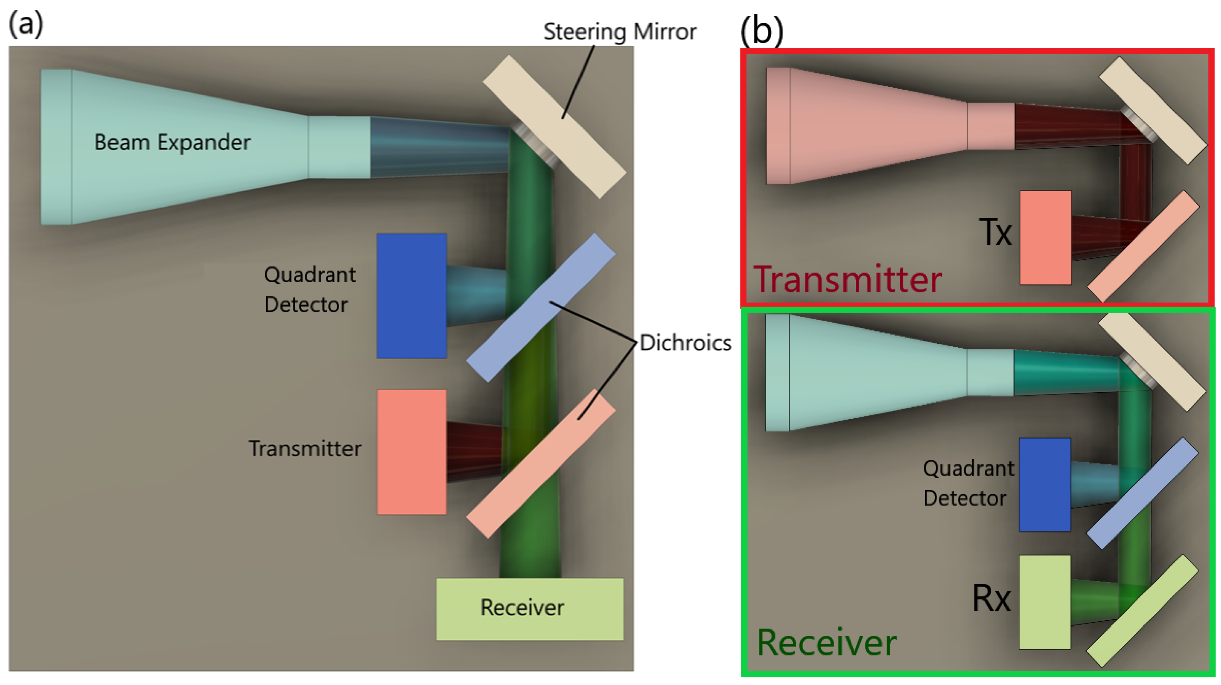
Figure 1 illustrates the optical architectures of terminal technologies incorporating steering mirrors. When the same steering mirror is employed for both the transmitter and receiver, the steering functionality must compromise between speed (to correct for satellite jitter), size (to decrease the natural divergence induced by diffraction for the transmitter beam or maximize the beam collection capability on the receiver channel), and stroke amplitude (linked to the Field of Regard (FoR)).
In a duplex co-located PAT system, as depicted in
Figure 1a, a single mirror is used to steer both the transmitted and received optical signal. While this configuration offers the advantage of a simpler design [
9,
10], it typically requires a separate beacon channel, along with the use of dichroic beamsplitters to separate the send and receive beams. These beam splitters necessitate the use of different data wavelengths on opposing terminals.
Alternatively, a duplex bistatic configuration, shown in
Figure 1b, features separate transmitter and receiver optical systems. This approach provides greater versatility in decoupling the channels, allowing customization of the FoV and divergence for each path to meet the specific requirements of both the transmitter and receiver.
This paper describes a steering mirror design which can be used on the receiver side of the ISL. It incorporates a two-axis mirror to increase the angular FoR of the receiver satellite, enabling the use of a small and fast Avalanche Photodiode Detector (APD). Smaller APDs have a higher cutoff frequency, and current commercial technology achieves up to 4 GHz on a 40-micron photosensitive area. Commercial off-the-shelf (COTS) actuators and optical encoders are used, offering a simple and compact solution for future CubeSat laser communication terminals.
2. Steering Mirror Design and Trade-Offs
With the growing applications of steering mirrors, the market has seen the introduction of a diverse range of commercial products [
12]. These solutions are available in a selection of actuator categories, including from electrostatic MEMS actuators, magnetic voice coils and piezo-stack micro-displacement amplifiers [
13,
14,
15]. Each technology comes with its own advantages and trade-offs. MEMS mirrors, for instance, are light weight and have low power consumption. However, their lower actuating forces require the use of lower mass mirrors, thereby restricting aperture and optical power handling [
16]. Voice coil actuators offer the advantage of higher actuation forces, enabling the use of larger mirrors with enhanced power handling and travel range. This comes at the expense of increased power consumption, heat generation, and limited resolution. Steering mirrors employing opposing pairs of piezo-stacks, which drive micro-displacement amplifiers, can move a larger-diameter mirror with high pointing resolution, at the expense of lower deflection angles. It is important to note that all of these actuator types require some power to maintain a fixed pointing angle, with the mirror returning to an uncontrolled position when powered off. A qualitative comparison of these primary actuator categories is shown in
Table 1.
For the receiving channel, a large mirror aperture is desirable to improve the signal-to-noise ratio in high-speed communications. Given the successful demonstration of body pointing for the coarse steering of CubeSat laser communications in previous missions [
6,
17], there is flexibility in relaxing the requirement for high steering speeds on the receiving channel. This allows for a strategic trade-off, sacrificing speed for increased precision or larger scan angle.
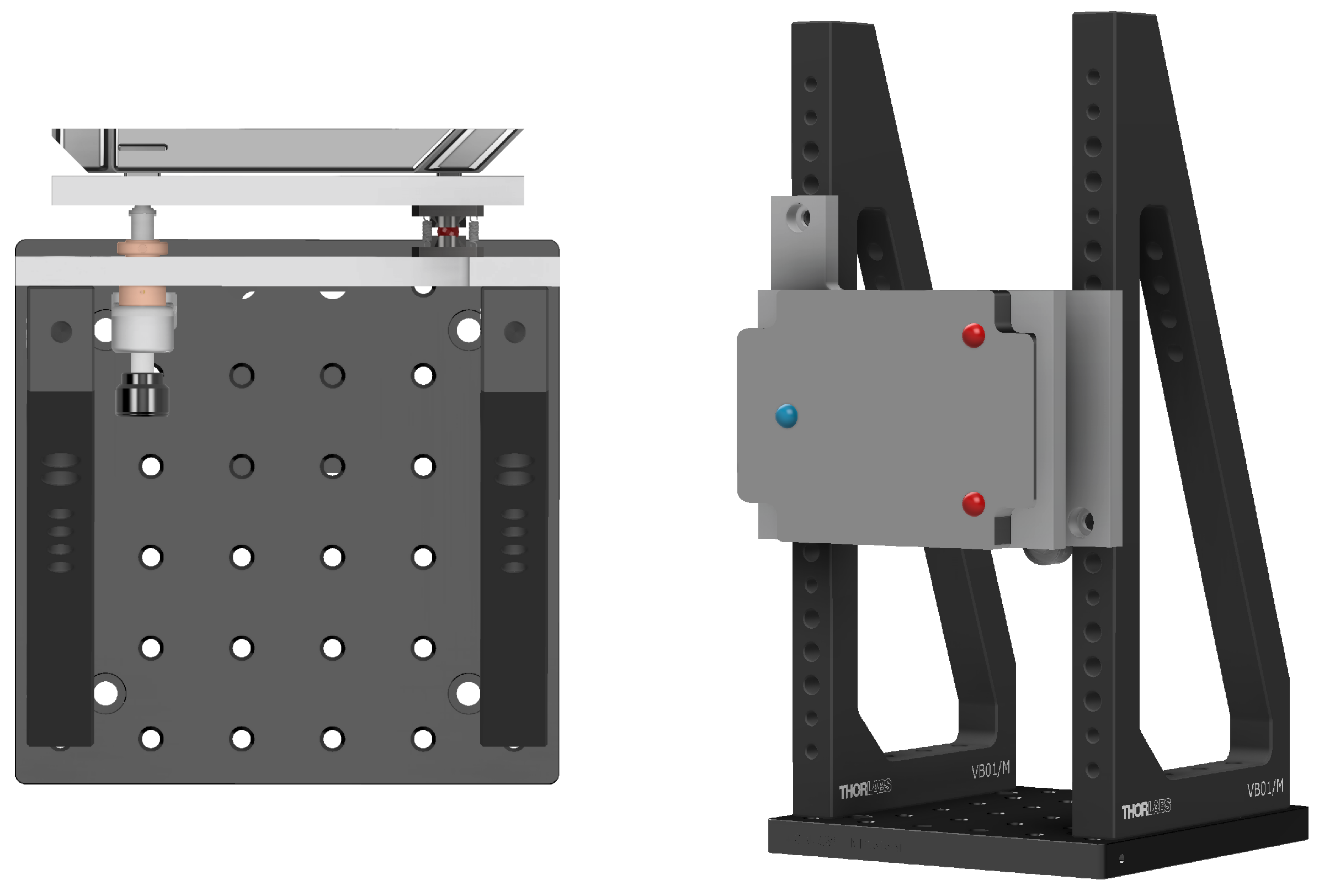
The increased size of the mirror assembly allows for a broader exploration of actuator technologies and mechanical designs. Here, a simple kinematic mount was developed, featuring a spherical ball joint to facilitate tip and tilt movement. This movement is controlled by two piezoelectric inertia stick slip actuators (PIA13VF, Thorlabs, Ely, UK). The mirror itself has a broadly rectangular aperture, measuring 130 × 90 mm. A rendering of the mirror and mount is illustrated in
Figure 2, with the positions of the spherical joint and actuator tips marked in blue and red, respectively. The placement of the actuators with respect to the pivot point results in the actuators being coupled for steering the mirror about the horizontal and vertical axes, as depicted in
Figure 2. To pivot around a vertical axis, both actuators must be driven in the same direction. Conversely, to pivot the mirror around its horizontal axis, the actuators must be driven differentially. The distance of the actuator from the pivot axis can be adjusted to optimize the pointing performance, mirror stroke and angular steering speed. Positioning the actuators closer to the pivot axis will increase the slew rate and angular range of the mirror, with a trade-off of reduced pointing resolution.
Inertia stick slip actuators work by using a piezo stack to turn a lead screw. These actuators provide an extended travel range of 13 mm, coupled with a fine step size of 20 nm, making them well suited for precisely steering a mirror over a long working range. A significant advantage of these actuators is that they are self-locking when at rest, eliminating the need for constant power to maintain a set pointing angle. This characteristic is valuable in applications with tight power budgets, such as in CubeSats. The limitations of these actuators are the relatively slow travel speeds of around 3.5 mm/min, and the piezo hysteresis requiring external feedback for precise positioning.
3. Control Feedback
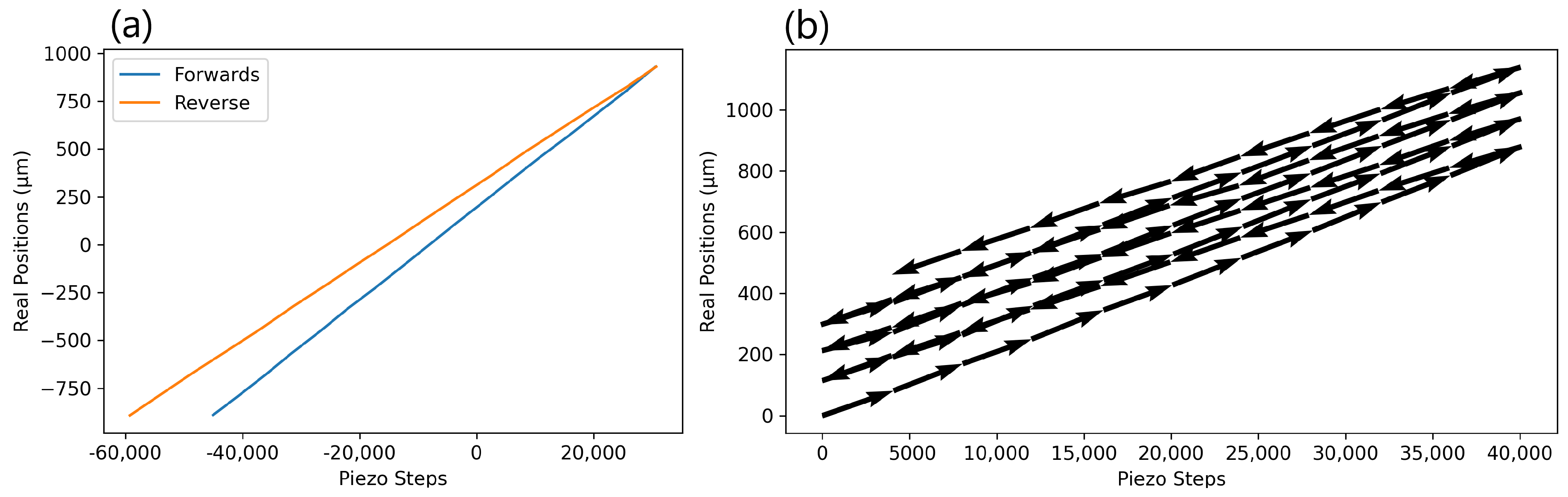
The stick slip piezo actuators used in this design exhibit significant hysteresis, with the size of the forward and reverse steps differing by approximately 16%, as illustrated in
Figure 3a. With the actuator unloaded, the mean forward step size was measured as 24.1 nm, and the mean reverse step size as 20.3 nm. Consequently, counting the number of commanded steps does not provide an accurate measure of actuator position, as the 16% positioning error will accumulate with multiple changes in direction. An example of this is shown in
Figure 3b, which depicts the position of the actuator tip over a series of forwards and backward movements, highlighting the forward drift of the 0 step position with each successive pass.
For accurate positioning of the actuators, a form of closed-loop control is essential. One option would be to use a mechanically coupled feedback sensor such as a linear variable differential transformer, with the pushrod attached to the back of the mirror. The downside of these feedback sensors is that a malfunction or jamming could mechanically lock the actuator in place. A more robust method employs non-contact sensors, such as optical encoders. The sensor receives the light directed onto a coded reflective pattern to track movement. Single-channel encoders can monitor movement speed, while quadrature encoders can be used to also track the direction of motion.
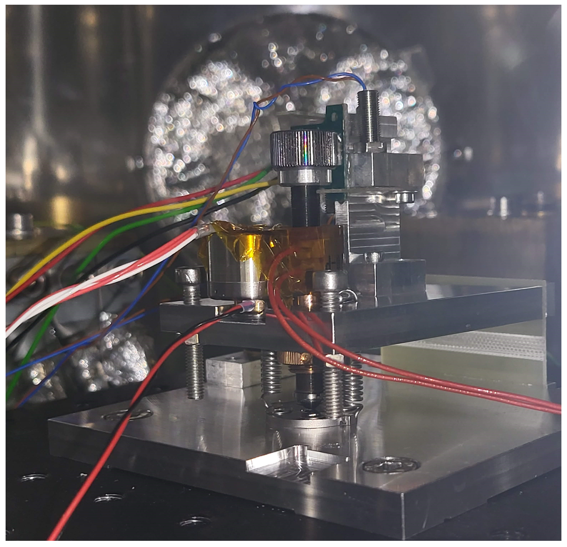
While some commercial products come with built-in optical encoders, they are generally much bulkier and heavier, weighing 200 g compared to the 55 g PIA13VFs. This increased size and weight makes these actuators less practical for use in CubeSats. Therefore, an in-house solution was developed, integrating optical encoder feedback into the COTS Thorlabs actuators. The chosen optical encoder for this setup is the AEDR-8300-1K2 quadrature encoder (Broadcom, Palo Alto, CA, USA). A critical specification for these encoders is the reflectance of the coded pattern. Rather than requiring a simple black-and-white barcode-style pattern, the brighter areas of the pattern must have a specular reflectance of over 60%. To achieve this, a fine straight knurled knob was diamond-turned, providing a highly reflective surface on the raised portions of the knurling. An image of the encoder wheel is displayed in
Figure 4a. The knob features 72 grooves, corresponding to 288 pulses per revolution with the quadrature encoder. Along with the 1/4″ × 80 fine thread lead screw on the actuators, the encoder should provide a resolution of 1.1 µm. Since these inertial actuators require a mass on the screw thread, the only additional weight for this system is the encoder PCB, adding just 6 g to the actuator’s mass.
Figure 4b displays a plot of the actuator tip position against the encoder counts for 20 successive movements, using the encoder feedback for position control. This can be compared to
Figure 3b, where the commanded piezo steps are used for feedback. The 12
m spread on the actuator position originates partially from the backlash of the measurement probe, and partially from the delay in communication between the prototype encoder electronics and the motor controller.
4. Optical Test
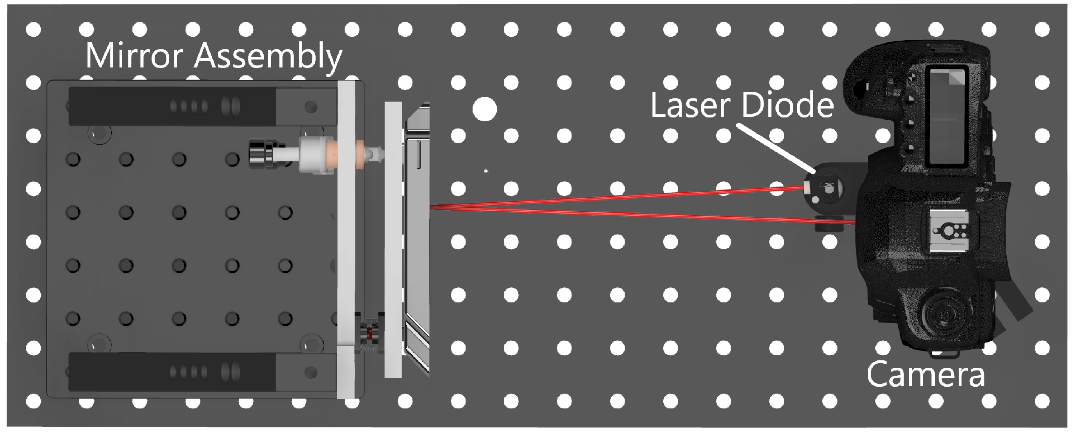
To create a realistic test environment for the closed-loop actuator, a prototype slow steering mirror was constructed, with a rendering of the set-up shown in
Figure 5. The mirror is flat and was machined using single-point diamond turning. A custom kinematic mount was designed to steer the mirror, employing a pair of these stick-slip actuators and a spherical ball joint to facilitate movement. The actuators are positioned 82 mm horizontally from the pivot point, and 30 mm vertically on either side of the horizontal pivot plane. The mirror is tensioned against each actuator by two extension springs.
For optical measurements of the mirror’s movement, a simple set-up using a 658 nm laser diode and a DSLR camera was devised. The laser diode was positioned as close to the bore axis of the camera sensor as possible, to prevent off-axis effects. The camera was set up perpendicular to the nominal position of the mirror, and the laser was directed to land on the center of the camera sensor after reflecting off of the mirror.
The camera sensor was positioned at a distance of 280 mm from the surface of the steering mirror. The sensor has a pixel pitch of 6.41 m, corresponding to a resolution of 11 rad of mechanical angular movement of the mirror.
The camera and both encoders were connected to two Arduino Uno R4s (Arduino, Turin, Italy) and linked to the ThorLabs motor controller using Python (Ver 3.10.9). The mirror was then commanded to repeatedly move through a range of positions, addressing four extreme positions and a central one, with an image recorded at each point. The centroids of the laser spot were calculated for each image using a center-of-mass method and is plotted in
Figure 6 [
18]. Taking the mean of the five positions, the maximum spread of the spots on the camera sensor was found to be 4.2 pixels, with a standard deviation of 1.1 pixels. This corresponds to a maximum spread of 45
rad, or 3.9
m at the actuator tip. The standard deviation of the actuator position was calculated to be 1.0
m. The horizontal angular slew rate of the mirror was measured as to be 1.05 mrad/s, with a vertical slew rate of 1.92 mrad/s.
The repeatability along the long axis of the mirror is limited by the delay in synchronizing both motors and actuators. Although the encoder steps are counted using hardware interrupts on the two Arduinos (one for each actuator), the step counts are read by the controlling computer via polling of the serial connection, which can result in a one-step delay at high motor speeds. The Arduinos act as converters of the raw quadrature signal into a count number read by the laptop, where the decision is taken to continue the counting or to stop the motor if the number of the desired count has been achieved. This delay could be reduced by communicating to the motor controller from the Arduinos directly.
The overall precision of the mirror mount can also be adjusted by optimizing the positions of the actuators. Moving the actuators further from the pivot point will increase angular resolution at the expense of decreasing the angular speed.
5. Active Stabilisation Testing
Perturbations in the CubeSat’s pointing direction are induced by various disturbance torques, including aerodynamic drag, solar radiation pressure, thermal radiation, Earth’s gravity gradient, residual magnetism in the satellite structure, and variations in Earth’s magnetic field [
19]. To mitigate these disturbances during operation, the attitude determination and control system (ADCS), typically operating magneto-torquers or reaction wheels in CubeSats, dynamically adjusts the pointing direction at regular intervals. Despite the precision attainable with a star tracker for attitude measurement, the robustness of a link is ultimately contingent on the satellite’s ability and accuracy in adjusting its attitude to the intended direction for laser beam transmission.
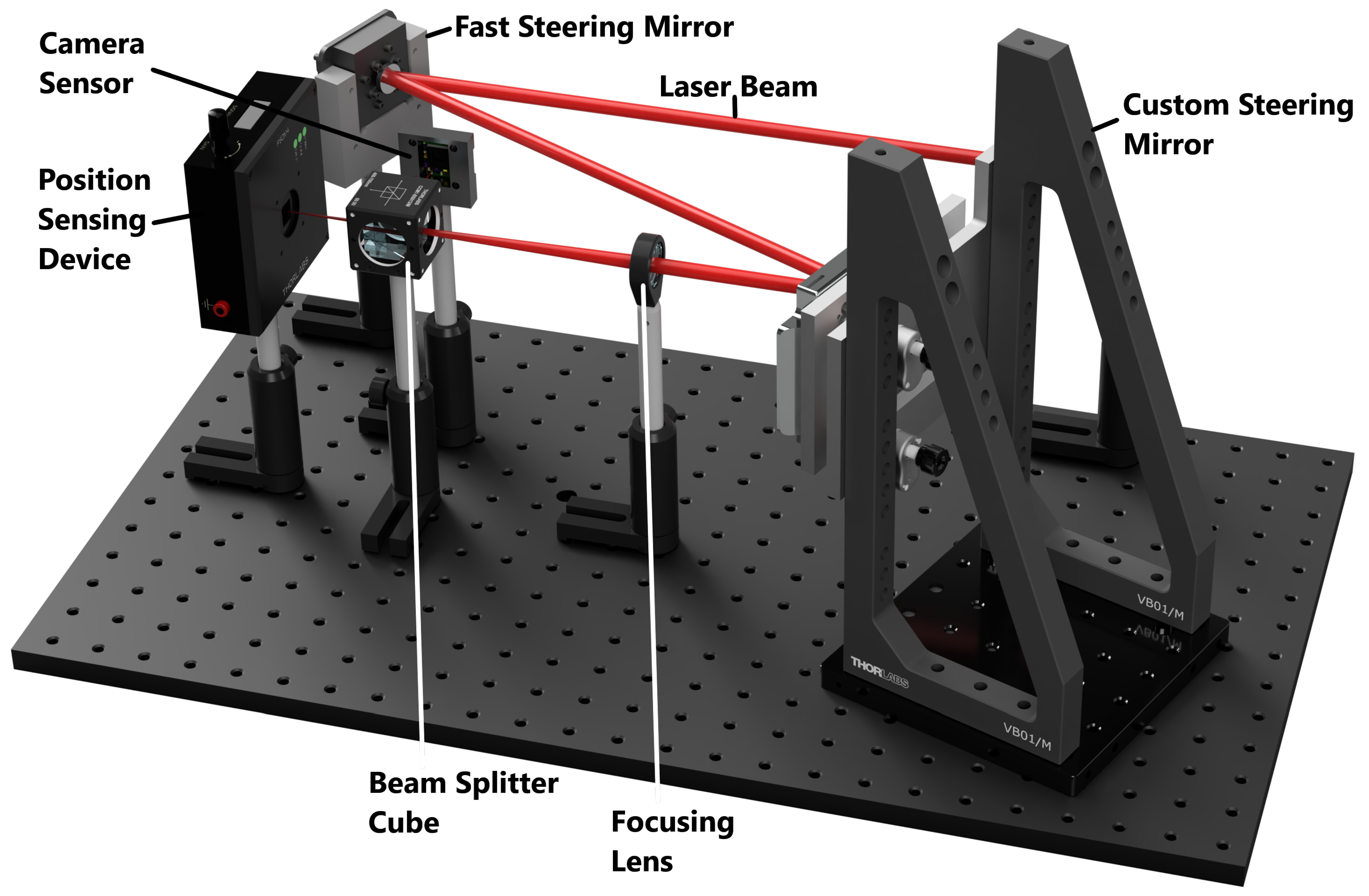
One of the key applications of a steering mirror in a communications satellite is to correct for this platform jitter, keeping the incoming beam continuously centered on the receiving detector. To simulate this scenario on an optical bench, a set-up using two steering mirrors was devised, illustrated in
Figure 7. A collimated 633 nm laser beam was first directed onto a small, piezo-stack-driven fast steering mirror (silver coated P-FSM150S, Cedrat Technologies, Meylan, France), which then directed the beam onto the custom mirror under test conditions. The beam was then focused onto both a high-resolution camera sensor and a Thorlabs PSDM4 position-sensing device (PSD) using a beam-splitting cube.
The camera sensor was used to record the exact position of the beam spot with a high spatial resolution. Using a center-of-mass method, the centroid of the laser spot was calculated and stored in real time in order to reduce storage space needed for longer experiments.
The PSD was read out using a high-resolution data logger, with the position measurement fed into the Python control code, providing real-time feedback. The control algorithm used was a simple proportional–integral–derivative (PID) loop, taking the distance from the center position as the input. The proportional control ramps the actuator speed up as the spot moves further from the center of the sensor. The integral control acts to minimize positioning error when the spot is close to the center of the sensor, while the derivative control is optimized to reduce overshoots and control loop-induced oscillations. PID outputs are calculated separately for the X and Y displacements measured by the PSD, and summed to give the final actuator commands.
The piezo-stack-driven mirror was instructed to replicate a simulated jitter profile with a 1 Hz sampling rate, exhibiting an angular variation of ±3.5 mrad amplitude in two Euler angles (yaw and pitch, corresponding to the x-axis and y-axis, respectively) at a maximum speed of 7 mrad/s. The simulated profile is designed to model attitude changes during the link, representing instances when the control system dynamics rectify the pointing direction to counteract disturbances. Throughout this process, the steering mirror is tasked with maintaining the laser beam centered onto a small-sized APD via the closed loop within an FPA to ensure uninterrupted communication.
The pointing angles in pitch and yaw are depicted in
Figure 8a—top. The profile has been generated randomly using the available Python code (refer to Data Availability Statement). It comprises a random time series that underwent smoothing through cumulative sum and a rolling average over 60 s. To eliminate low-frequency angular drift that might exceed the FSM maximum range of
, the time series is further filtered with a high-pass filter, removing frequencies lower than
Hz. When the jitter profile is applied onto the FSM in the experimental setup, the mirror’s movement induces a ‘wandering’ of the beam spot around the detector plane, represented by the blue line in
Figure 8b. When active corrections are enabled on the actuated steering mirror through the closed-loop system reading from the PSD, the beam spot’s position becomes significantly more focused on the camera sensor. The pointing error becomes strongly attenuated (
Figure 8a—bottom) when the active mirror is engaged, and the track remains within an angular extent of 600
rad. This signifies a more than 5-fold improvement in concentration compared to the uncorrected case, where the point track spreads over an angular extent of approximately 3400
rad.
The outlying peaks in the actively corrected data are due to the sharp motions in the jitter profile, which correlate with satellite platform maneuvering by the ADCS. Due to the limited 8 Hz readout rate of the PSD, fast changes in the direction of the satellite platform are under sampled, resulting in a time lag before the control algorithm updates. This results in jumps of the angular displacement of the spot, seen as small tails in the orange track in
Figure 8. This effect could be minimized by using faster readout electronics for the PSD, or including communication between the ADCS and mirror controllers to predict sharp movements of the ADCS. Also notable is the elliptical shape of the spot track during active corrections. This is caused by the asymmetric mounting of the actuators about the pivot plane, meaning the mirror is able to rotate more quickly about its horizontal axis than its vertical axis. This could be solved by placing the actuators equidistantly in vertical and horizontal position relative to the pivot point.
6. Thermal Tests
While the PIA13VF actuators are rated for vacuum conditions, the AEDR8300 spec sheet does not provide information on vacuum operating conditions. Additionally, neither of the AEDR or PIA13VF is rated for operation below −20 °C. A test rig consisting of an actuator, an encoder and datum switches was created, depicted in
Figure 9.
The chamber was pumped down to a vacuum of 3 × 10⁻⁶ mbar, and the actuator was cooled to a temperature of 234 K (−39 °C). While the actuator moved between the two end-limit switches, the encoder pulses were recorded by an oscilloscope. The pulse train appears identical to the measurements made under room temperature and pressure. These results indicate that the system functions correctly under these extreme conditions.
7. Conclusions
In summary, a novel method of adding closed-loop control to a consumer-off-the-shelf piezo actuator is described. Using low-cost electronics, the actuator can be positioned in a closed loop with a feedback error repeatability of 1.0 m at 1 and an accuracy in line with the angular resolution of the encoder, defined by the period of the lines on the screw knob.
Two actuators were combined into a custom kinematic mount, producing a large-aperture steering mirror with repeatable angular positioning of less than 45 rad. Due to the self locking nature of the actuators, the mirror does not require power to maintain a pointing direction, making it ideal for low-power applications. Using the mirror to actively center an incoming beam following a random jitter pattern, the mirror provided over a 5-fold concentration of angular extent on the detector. The actuator assembly has also been successfully tested at low temperatures under vacuum, potentially enabling the assembly to be used in space applications.
Author Contributions
Conceptualization, C.G., D.B., O.Y., A.R., R.B., E.S., R.T.W. and C.B.; methodology, C.G., D.B. and C.B.; software, C.G.; validation, C.G., D.B. and C.B.; formal analysis, C.G. and C.B.; investigation, C.G., D.B. and C.B.; resources, C.B.; data curation, C.G. and C.B.; writing—original draft preparation, C.G.; writing—review and editing, all; visualization, C.G. and C.B.; supervision, C.B.; project administration: E.S., R.T.W., R.B. and C.B.; funding acquisition, E.S., R.T.W., R.B. and C.B. All authors have read and agreed to the published version of the manuscript.
Funding
This research was funded by the UK Space Agency grant number UKSAG22_0042.
Data Availability Statement
Acknowledgments
The authors would like to thank e2E Services Ltd./Telespazio-UK, SMS Electronics Ltd. and Smart Sentry Ltd., partners in the NSIP Phase 3 Project “ALIGN Laser Optical Communications for CubeSats”, for their input and support.
Conflicts of Interest
The authors declare no conflicts of interest.
References
- Su, Y.; Liu, Y.; Zhou, Y.; Yuan, J.; Cao, H.; Shi, J. Broadband LEO Satellite Communications: Architectures and Key Technologies. IEEE Wirel. Commun. 2019, 26, 55–61. [Google Scholar] [CrossRef]
- Kaymak, Y.; Rojas-Cessa, R.; Feng, J.; Ansari, N.; Zhou, M.; Zhang, T. A Survey on Acquisition, Tracking, and Pointing Mechanisms for Mobile Free-Space Optical Communications. IEEE Commun. Surv. Tutor. 2018, 20, 1104–1123. [Google Scholar] [CrossRef]
- Fields, R.; Kozlowski, D.; Yura, H.; Wong, R.; Wicker, J.; Lunde, C.; Gregory, M.; Wandernoth, B.; Heine, F. 5.625 Gbps bidirectional laser communications measurements between the NFIRE satellite and an Optical Ground Station. In Proceedings of the 2011 International Conference on Space Optical Systems and Applications (ICSOS’11), Santa Monica, CA, USA, 11–13 May 2011; pp. 44–53. [Google Scholar] [CrossRef]
- Kolev, D.; Takenaka, H.; Munemasa, Y.; Akioka, M.; Iwakiri, N.; Koyama, Y.; Kunimori, H.; Toyoshima, M.; Artaud, G.; Issler, J.L.; et al. Overview of international experiment campaign with small optical transponder (SOTA). In Proceedings of the 2015 IEEE International Conference on Space Optical Systems and Applications (ICSOS), New Orleans, LA, USA, 26–28 October 2015; pp. 1–6. [Google Scholar] [CrossRef]
- Schmidt, C.; Rödiger, B.; Rosano, J.; Papadopoulos, C.; Hahn, M.T.; Moll, F.; Fuchs, C. DLR’s Optical Communication Terminals for CubeSats. In Proceedings of the 2022 IEEE International Conference on Space Optical Systems and Applications (ICSOS), Virtual, 29–31 March 2022; pp. 175–180. [Google Scholar] [CrossRef]
- Rose, T.S.; Rowen, D.W.; LaLumondiere, S.D.; Werner, N.I.; Linares, R.; Faler, A.C.; Wicker, J.M.; Coffman, C.M.; Maul, G.A.; Chien, D.H.; et al. Optical communications downlink from a low-earth orbiting 15U CubeSat. Opt. Express 2019, 27, 24382. [Google Scholar] [CrossRef] [PubMed]
- Rose, T.S.; Rowen, D.W.; LaLumondiere, S.; Werner, N.I.; Linares, R.; Faler, A.; Wicker, J.; Coffman, C.M.; Maul, G.A.; Chien, D.H.; et al. Optical communications downlink from a 1.5U Cubesat: OCSD program. In Proceedings of the International Conference on Space Optics ICSO 2018, Chania, Greece, 9–12 October 2018; p. 111800J. [Google Scholar] [CrossRef]
- Cahoy, K.; Grenfell, P.; Crews, A.; Long, M.; Serra, P.; Nguyen, A.; Fitzgerald, R.; Haughwout, C.; Diez, R.; Aguilar, A.; et al. The CubeSat Laser Infrared CrosslinK Mission (CLICK). In Proceedings of the International Conference on Space Optics ICSO 2018, Chania, Greece, 9–12 October 2018; p. 111800Y. [Google Scholar] [CrossRef]
- Dresscher, M.; Human, J.D.; Witvoet, G.; Van Der Heiden, N.; Den Breeje, R.; Kuiper, S.; Fritz, E.C.; Korevaar, C.W.; Van Der Valk, N.C.; De Lange, T.J.; et al. Key Challenges and Results in the Design of Cubesat Laser Terminals, Optical Heads and Coarse Pointing Assemblies. In Proceedings of the 2019 IEEE International Conference on Space Optical Systems and Applications (ICSOS 2019), Portland, OR, USA, 14–16 October 2019. [Google Scholar] [CrossRef]
- Tomio, H.; Grenfell, P.; Kammerer, W.; Serra, P.; Čierny, O.; Lindsay, C.; Garcia, M.; Cahoy, K.; Clark, M.; Coogan, D.; et al. Development and Testing of the Laser Transmitter and Pointing, Acquisition, and Tracking System for the CubeSat Laser Infrared CrosslinK (CLICK) B/C Mission. In Proceedings of the 2022 IEEE International Conference on Space Optical Systems and Applications (ICSOS 2022), Kyoto City, Japan, 28–31 March 2022; pp. 224–231. [Google Scholar] [CrossRef]
- Saathof, R.; Crowcombe, W.; Kuiper, S.; van der Valk, N.; Pettazzi, F.; de Lange, D.; Kerkhof, P.; van Riel, M.; de Man, H.; Truyens, N.; et al. Optical satellite communication space terminal technology at TNO. In Proceedings of the International Conference on Space Optics ICSO 2018, Chania, Greece, 9–12 October 2018; p. 111800K. [Google Scholar] [CrossRef]
- Milaševičius, M.; Mačiulis, L. A Review of Mechanical Fine-Pointing Actuators for Free-Space Optical Communication. Aerospace 2023, 11, 5. [Google Scholar] [CrossRef]
- Yoo, B.W.; Park, J.H.; Park, I.H.; Lee, J.; Kim, M.; Jin, J.Y.; Jeon, J.A.; Kim, S.W.; Kim, Y.K. MEMS micromirror characterization in space environments. Opt. Express 2009, 17, 3370. [Google Scholar] [CrossRef] [PubMed]
- Langenbach, H.; Schmid, M. Fast steering mirror for laser communication. In Proceedings of the 11th European Space Mechanisms and Tribology Symposium, ESMATS 2005, Lucerne, Switzerland, 21–23 September 2005; Volume 591, pp. 27–33. [Google Scholar]
- Zheng, H.; Lu, S.; Zhai, Q.; Huang, B.; Long, Y.; Zhao, Y.; Qi, J. Simulation and experiment of a diamond-type micro-displacement amplifier driven by piezoelectric actuator. J. Eng. 2020, 2020, 141–147. [Google Scholar] [CrossRef]
- do Vale Pereira, P.; Hunwardsen, M.T.; Cahoy, K. Characterization of laser thermal loading on microelectromechanical systems-based fast steering mirror in vacuum. Opt. Eng. 2020, 59, 1. [Google Scholar] [CrossRef]
- Schieler, C.; Robinson, B.S.; Guldner, O.; Bilyeu, B.; Garg, A.S.; Riesing, K.M.; Chang, J.T.; Hakimi, F. NASA’s Terabyte Infrared Delivery (TBIRD) Program: Large-Volume Data Transfer from LEO. In Proceedings of the Small Satellite Conference (SSC19-VI-02), Logan, UT, USA, 5–8 August 2019. [Google Scholar]
- Fosu, C.; Hein, G.; Eissfeller, B. Determination of centroid of CCD star images. Int. Arch. Photogram. Remote Sens. Spat. Inform. Sci 2004, 35, 612–617. [Google Scholar]
- Rawashdeh, S.A.; Straub, J. Attitude Analysis of Small Satellites Using Model-Based Simulation. Int. J. Aerosp. Eng. 2019, 2019, 11. [Google Scholar] [CrossRef]
| Disclaimer/Publisher’s Note: The statements, opinions and data contained in all publications are solely those of the individual author(s) and contributor(s) and not of MDPI and/or the editor(s). MDPI and/or the editor(s) disclaim responsibility for any injury to people or property resulting from any ideas, methods, instructions or products referred to in the content. |
© 2024 by the authors. Licensee MDPI, Basel, Switzerland. This article is an open access article distributed under the terms and conditions of the Creative Commons Attribution (CC BY) license (https://creativecommons.org/licenses/by/4.0/).

 ,
, 


