
Computational Mechanics for Turbofan Engine Blade Containment Testing: Fan Case Design and Blade Impact Dynamics by Finite Element Simulations

1
Department of Mechanical Engineering, Universidad de La Frontera, Temuco 4811230, Chile
2
Master Program in Engineering Sciences, Universidad de La Frontera, Temuco 4811230, Chile
3
Department ArGEnCo-MSM, University of Liège, 4000 Liège, Belgium
*
Author to whom correspondence should be addressed.
Aerospace 2024, 11(5), 333; https://doi.org/10.3390/aerospace11050333
Submission received: 2 February 2024
/
Revised: 12 April 2024
/
Accepted: 17 April 2024
/
Published: 24 April 2024
Abstract
:The harsh environment during airplane take-off and flights with complex operating conditions require a high dynamic and impact resistance capability of airplane engines. The design, development, and performance evaluation of new turbofan engines are generally performed through numerical simulations before a full-scale model or prototype experiment for certification. Simulations of fan blade containment tests can reduce trial–error testing and are currently the most convenient and inexpensive alternative for design; however, certification failure is always a risk if the calibration of material models is not correctly applied. This work presents a three-dimensional computational model of a turbofan for designing new engines that meet the certification requirements under the blade containment test. Two calibrated Johnson–Cook plasticity and damage laws for Ti64 are assessed in a simulation of a turbofan blade containment test, demonstrating the ability of the models to be used in the safe design of aircraft engine components subjected to dynamic impact loads with large deformations and adequate damage tolerance.
1. Introduction
To ensure the integrity of the aircraft and passengers, aero engines are designed to contain the detachment of a blade from both the fan and turbines without perforation of the casing. This failure is one of the most difficult challenges in the design process of an engine due to the large amount of energy, high speeds, and number of components involved, such as detached blades, remaining fan blades, casing, and bearing supports, among others. In addition, low cost must be maintained in designing and manufacturing new aircraft engine models. These efforts to improve engine integrity were the result of failure-related incidents in aircraft engine containment events [1].
The aerospace industry has experienced numerous aircraft accidents due to engine containment failures. In August 2008, the National Transportation Safety Board of the United States investigated an accident involving a Pratt & Whitney engine, where three consecutive high-pressure turbine blades fractured. Similarly, in February 2021, a Boeing 777-222 registered a Pratt & Whitney PW4077 number 2 engine failure during a flight from Denver to Honolulu. The investigation revealed that a titanium fan blade number 11 fractured due to low cycle fatigue. A total of 315 non-contained rotor failures were reported in commercial, general, and helicopter aviation between 1976 and 1984, and a further study by the US Federal Aviation Administration (FAA) showed that 676 non-contained engine failures occurred in fixed-wing aviation between 1969 and 1997 [2]. The large number of records of failed containment in aircraft engines has led both the FAA and researchers to study and analyze the impact generated by the detachment of a blade by obtaining information through different methods, both experimental and numerical [3].
Aircraft engine containment studies must consider the Federal Aviation Regulations (FAR Part 33—Airworthiness Standards: Aircraft Engines). Section 33.19 states that the design and manufacturing of compressor and turbine rotor casings must prevent damage from rotor blade failure. Energy levels and trajectories of fragments resulting from rotor blade breakage outside the compressor and turbine rotor casings must be defined. In addition to the design and manufacturing requirements, each applicant must demonstrate the engine blade containment test based on the specific Section 33.94, which describes the test conditions and results the engine must meet for certification. This test is performed on a real prototype of the new engine model, and its objective is to verify whether the aircraft engine can withstand the impact produced by a blade detaching during service. Therefore, the turbofan casing plays a fundamental role in the new engine design, as it must absorb the energy produced during this impact. The impact absorption capacity of the casing depends significantly on its shape, thickness, material, and manufacture technology.
Increasing the thickness of casings is not always a cost-effective solution for the aerospace industry because of the consequent increase in engine weight, higher fuel consumption, and higher carbon footprint for aircraft operations. For this reason, in recent decades, the focus of research has been to increase the strength of the engine casing without increasing its weight and even reduce the engine weight without losing strength. Different materials have been studied to achieve this objective, and they present a good weight–resistance ratio, where composite materials, aluminum, and titanium alloys can be found. The latter are of great interest to engineers and researchers since they have a good weight-to-strength ratio and high specific ductility at low and moderate temperatures.
Material deformation and damage processes depend heavily on operating factors, such as the speed and magnitude of mechanical loads, stress and deformation states, or temperatures. In extreme conditions such as high load and high-speed loading or elevated temperatures, these factors can lead to failure of a mechanical component or even catastrophic structural failure, causing damage of different magnitudes, including the loss of human lives. For this reason, engineering calculations and analyses are performed to predict the useful life and ensure the resistance of the components and structure. Constitutive models are mathematical representations used to predict the complex physical phenomena that occur during material deformation under loading [4,5,6,7,8,9,10,11]. The mechanical properties and behavior of the materials of interest are obtained through different experiments, depending on the types of loads and conditions of their application, such as temperature and strain rate [12,13,14,15]. Analytical models for predicting material behavior, based on physics and empirical models, are required to improve component design and increase aircraft efficiency. These models contain material-dependent constants obtained by analyzing experimental results and applying direct or inverse calibrations.
After several decades of research, numerical finite element simulations based on material models are emerging mainly in the aerospace industry [16]. Current results of the technique demonstrate its good approximation to reality, which has prompted its use for modeling complex tests such as the blade containment test [17,18,19] or the impact of an external object on the fan [20]. Therefore, accurate simulations with proper discretization and definition of real test boundary conditions can reduce the time and cost of producing a new aircraft engine model compared to destructive trial-and-error testing.
The Johnson–Cook plasticity model is used to model von Mises flow stress behavior as a function of equivalent plastic strain, equivalent plastic strain rate, and temperature [21]. Other constitutive models applied to predict the impact behavior of metals and alloys include the Zirilli–Armstrong (Z–A) model [22], the Bodner–Partom (B–P) model [23], the mechanical threshold plasticity model (MTS) [24], the Nemat-Nasser–Guo model (NN–G) [25], and the Khan–Huang–Liang model (K–H–L) [26]. However, the Johnson–Cook (J–C) constitutive model is the most widely used. Depending on the state and level of stresses and strains, damage may occur in the cavities and shear bands of the material subjected to dynamic loading. This process can be modeled using the Johnson–Cook progressive damage model, which considers both a damage initiation criterion and damage evolution [27].
This paper presents an innovative three-dimensional computational model of a turbofan to be applied to design new engines that meet the certification requirements under the blade containment test. Among the main objectives of this study is to evaluate a calibrated Johnson–Cook plasticity and damage law for Ti64 in a simulation of a turbofan blade containment test, demonstrating the ability of the model to be used in the safe design of an aircraft engine component subjected to dynamic impact loads with large deformations and adequate damage tolerance. In particular, this work contributes to aerospace and structural integrity required for a safe design of Ti64 parts, allowing the reduction in both trial and error and production costs of new aircraft engine prototypes and damage tolerant aerospace components.
2. Materials and Methods
2.1. Characteristic Properties of the Ti64 Titanium Alloy
Titanium alloys are attractive engineering materials for the aerospace, biomedical, and military industries primarily due to their high specific strength and ductility at low and moderate temperatures. In particular, Ti64 (Ti-6Al-4V) is the most widely used titanium alloy, despite its high cost, due to a good balance of processing properties such as good formability, plastic workability, heat treatability, and weldability [28]. Furthermore, the alloy is a very biocompatible substance that is lightweight, ductile, highly load-resistant, and corrosion-resistant [28,29,30]. It also exhibits anisotropic deformation behavior throughout the elastoplastic range, along with an asymmetric Young’s modulus, initial flow stress, and strain hardening rate [31]. Microstructural observations show primary α-grains, and hexagonal close-packed (hcp) structures embedded in a biphasic matrix (alternating lamellae of a primary α-phase and body-centered cubic β-phase) [28]. The chemical composition, determined directly by energy-dispersive X-ray spectroscopy (EDS), is shown in Table 1.
Split Hopkinson bar experiments are frequently used to characterize the high strain rate mechanical behavior of metals. These experiments yield the specimen’s strength and elongation history, reflecting its material and structural behavior. Calculating the actual material behavior from this overall response is not straightforward. The deformed specimen is very heterogeneous for materials such as Ti64 with low strain hardening. However, for fundamental materials research and modeling of constitutive materials, knowledge of the true effective stress versus plastic strain, strain rate, and temperature is essential [32]. The mechanical response of Ti64 alloy at different strain rates and temperatures reported in the literature is shown in Figure 1.
2.2. Johnson–Cook Plasticity and Damage Prediction Model for Ti64
The plasticity and damage model proposed by Johnson and Cook is an empirical constitutive model that arises from the need to calculate intense, impulsive loads due to high-velocity impacts and explosive detonations. This model includes, unlike other models, the strain rate dependence for both deformation and failure of the material [21,27].
2.2.1. Johnson–Cook Plasticity Model
The Johnson–Cook model of plasticity describes the equivalent stress () (Equation (1)) of the material as a function of the equivalent plastic strain (), the equivalent plastic strain rate (), and the homologous temperature ().
The term corresponds to the elastic limit at a reference temperature and reference strain rate . The strain hardening coefficient and exponent describe the reference stress–strain curve, while identifies the material’s strain rate sensitivity. The thermal softening is described by the exponent.
The homologous temperature (Equation (2)) expresses the ratio between the absolute deformation temperature of the material to its melting point [39,40,41].
Deformation occurring at high speed is modeled under adiabatic conditions, and an arbitrary percentage of the plastic work occurring during deformation is transformed into heat. For many materials, between 90 and 100% of the plastic work is dissipated as heat.
2.2.2. Johnson–Cook Damage Model
Depending on the state and level of stress and deformation, damage may occur close to cavities and shear bands of the material subjected to dynamic loads. This process can be modeled macroscopically and continuously using the Johnson–Cook progressive damage model. This model supports the specification of the damage initiation criterion, as well as the evolution of damage [27,42].
The Johnson–Cook damage model (Equation (3)) determines the fracture deformation as a function of stress triaxiality , strain rate , and temperature .
where is the triaxiality of the stress state defined as the ratio of the hydrostatic pressure over the equivalent von Mises stress [27,43].
The parameters with are damage-related material constants.
Fracture occurs when the damage parameter in Equation (4) increases with the cumulative plastic strain reaching a value of 1 [43].
To model the behavior of the alloy during a blade containment test necessary for the design of the turbofan engine, two sets of parameters of the Johnson–Cook law of plasticity and damage for the same batch of Ti64 are used: the reported model constants by Tuninetti et al. [35] and the constants given in P. Verleysen and J. Peirs [43].
In the previous work [35], an hybrid calibration technique for the Johnson–Cook model of Ti64 was applied by combining direct and inverse strategies. The direct calibration strategy included the linear regression method, and the generalized reduced gradient technique, while the inverse calibration strategy was performed by finite element simulations and the Levenberg–Marquardt approach. To determine and , the direct calibration method of the Johnson–Cook plasticity law was applied using the strain–stress curves of Figure 1. The Johnson–Cook damage parameters , and were calibrated at reference conditions of strain rate and temperature with the direct method by adjusting the experimental evolution of the computed average fracture strain with the average stress triaxiality using the generalized reduced gradient technique. These damage parameters were assessed and validated with the numerical predictions from an accurate micromechanical damage model of Ti64. Furthermore, strain rate- and temperature-dependent damage constants, and , were obtained through the inverse calibration method using the large strain simulations of uniaxial tensile tests. The inverse method computed the average strain and the necking profile at fracture required to calculate the stress triaxiality by the Bridgman criterion, and the damage model calibration was completed by linear regression. In contrast, the Johnson–Cook damage and plasticity model of P. Verleysen and J. Peirs [43] followed an iterative scheme of optimization [32]. Initial Johnson–Cook model constants from the literature [44] were optimized using shear, plane strain, and tensile experiments.
The results of the simulations obtained from the two models are compared and evaluated, determining their respective errors, and investigating the origins of the possible differences produced. The same engine model, edge conditions, and blade containment test conditions are used. The material parameters are shown in Table 2.
2.3. Finite Element Simulation of Containment Test
The turbofan casing must be properly designed to protect the aircraft from any impact from external objects or detachment of internal engine parts, avoiding damage to the fuselage and fuel tank and loss of life [45,46,47]. To certify the structural integrity of aircraft engines, the blade containment tests is applied at the fan operating speed [48]. The Federal Aviation Regulation (FAA) Part 33.94 contains technical requirements for engine containment, such as designs to prevent damage from rotor blade failure. These failures must occur in the outermost retention groove or integral blade rotor discs, with at least 80% of the blade being affected [49].
The Ansys computational design tool through explicit finite element dynamics with large deformation is employed for the turbofan containment testing. The Johnson–Cook model from Tuninetti et al. is used first to correlate the qualitative and observable behavior of the impact dynamics in real containment test conditions. Furthermore, a Johnson–Cook model reported in the literature for the Ti64 is considered to assess the numerical predictions of this study.
2.3.1. Turbofan Model and Boundary Conditions
A casing and fan geometry based on the turbofan Trent 1000 from the Rolls-Royce company [50] is used to simulate the blade containment test. The model and the boundary conditions are shown in Figure 2. A fixed support condition was imposed in the bolted connections of the casing with the brackets from pilot or struts of the aircraft wings (Figure 2b). This type of union restricts the 6 degrees of freedom (displacement and rotation in the different coordinate axes). For the fan, the constrained condition imposed allows only axial rotation as shown in Figure 2c. A constant angular speed of 1440 rad/s was set for the fan (rotor and blades) and as initial speed for the blade detached during service (Figure 2d). This speed is 10% higher than the maximum operating speed of the turbofan (12,000 rpm), a critical condition considered in this design to ensure engine safety. The simulation time for the impact is 0.002 s. It should be noted that previous studies [17] suggested using a pre-stress and induced deformation of the ejected blade; however, this is not considered at this research stage due to the insignificant variation in the results reported [19].
2.3.2. Meshing of the Turbofan Model
For the blade containment test model, hexahedral and tetrahedral elements were used. While tetrahedral elements offer flexibility and adaptability for the discretized model, hexahedral elements are known as more efficient and stable for large deformations and damage. The linear structural hexahedral elements were chosen for the fan blades and the detached blade with an element size of 35 mm (Figure 3a and Figure 3b, respectively). Tetrahedral elements with an element size of 80 mm were used for the rotor as shown in Figure 3c. The turbofan casing is divided into 6 axial zones, with mesh refining in the blades’ impact zones. The hexahedral elements in the casing shown in Figure 3d, from left to right refining zones, have sizes of 35 mm, 25 mm, 25 mm, 25 mm, and 35 mm. The resulting mesh consists of a total of 361,035 elements.
2.3.3. Structural Integrity Assessment and Casing Design Adaptation
To ensure the structural integrity of the turbofan and evaluate the capacity of the innovative development and work presented in this study for aerospace engineering design, different models with increased thickness variation are investigated. The thickness of the casing is directly correlated to its ability to absorb deformation energy during impact. The proposed casing model should aim to confine the explosion by undergoing plastic deformation, while enabling destruction of the blades. The accumulated plastic strain energy and material damage parameter will be evaluated as design decision criteria, while the stress distribution and plastic strain are also compared with the available experimental material data.
3. Results and Discussion
3.1. Qualitative Model Assessment with Real Containment Test Impact Dynamics
To ensure the reliability of the proposed finite element model of the turbofan containment test, with the selected boundary and initial conditions, material model constants, and software capabilities, the impact dynamics characteristics observed in real testing conditions are first contrasted with the obtained numerical simulations (Figure 4). The simulation predictions of the dynamics of impact achieved a good qualitative correlation with the experimental blade containment test (Figure 4). Three stages are selected. The moment when the detached fan blade initiated the impact contact with the casing (Figure 4a,b), when the blade located at the back of the detached blade was impacted and deformed (Figure 4c,d), and the last stage is the instant when the two blades impacted the case and fractured (Figure 4e,f). The numerical results using the proposed material and fan model predicts, in a direct correlation, the impact dynamics observed during the fan explosion. Similar phenomena have been reported by another study [51]. Note that this is a qualitative validation that partially demonstrates the capability of the generated model, which allows us to model the interaction between the blades and case using an adapted model of Ti64 alloy.
Once the simulation was completed, the maximum values of von Mises equivalent stress, equivalent plastic deformation, and damage parameters were obtained for the different components of the turbofan (Table 3). It should be noted that the maximum damage parameter for the elements is 1, indicating the failure or rupture of the analyzed component. Concerning the maximum values obtained during the analysis for the equivalent stress, it is observed that they are consistent with the ranges contained in the test specimens reported in Figure 1.
Figure 5 shows the last instant of the impact obtained by the complete simulation of the turbofan, where the deformed components, fracture zones, and von Mises equivalent stress distribution can clearly be seen (Figure 5a). Fragments ejected (Figure 5b) out of the casing due to its fracture (Figure 5c) indicate a failure in the preliminary design of the turbofan.
The components suffer great deformations, stresses, and even damage in the parts where the impact is generated due to the large amount of energy and the low plastic work absorption capacity of the components, mainly the turbofan casing. The blade presents great deformations and stresses that almost completely destroy it. The casing deforms greatly in the impact zone of the blade until it fractures. The stress levels achieved in most of the components exceed the resistance capacity observed in dynamic tests (Figure 1), which is consistent with the achieved deformation rates of the order of and elevated levels of hardening due to large deformations.
3.2. Comparison of Simulation Results with Two Sets of Parameters of the Johnson–Cook Law of Plasticity and Damage
Two simulations of the blade containment test were conducted using the same geometry, mesh, boundary, and initial conditions, except for the material parameters. The parameters identified by P. Verleysen and J. Peirs, [43] were used in one simulation while for the other simulation, those published by Tuninetti et al. [35] were used. The results obtained for the equivalent von Mises stress, equivalent plastic strain, and damage parameter are shown in Table 4. It should be noted that the results shown are the maximum values obtained during the simulation up to a time of 0.001 s.
The manner in which the test data were post-processed for model adjustment is primarily responsible for the visible discrepancy in results. As reported by P. Verleysen and J. Peirs, 2017 [43], the parameters of the Johnson–Cook plasticity and damage law obtained from cylindrical bars from the same batch were adjusted with engineering stress–strain curves, while in the work of Tuninetti et al. in 2024 [35], the stress–strain curves in real definition were used. These significant differences are found due to using different stress–strain definitions, where the definition of true stress–strain is generally applied to calibrate models that describe large levels of plastic deformation [52]. In addition to this effect on the load response prediction, significant differences can be encountered if the curves are obtained for local or average stress values, where higher local stress levels (post-necking) used in the identification allow for more precise adjustment of the strain hardening [31,53] and damage [54].
3.3. Turbofan Casing Redesign
The thickness of the casing initially studied is modified to evaluate the capacity of the turbofan to absorb the impact better without fracturing. In the first variation, the thickness was increased by approximately 23%, which was insufficient to contain the impact well, resulting in considerable damage within the structure as in the initial casing (Figure 5). In a second iteration of the design, the thickness is increased by a greater percentage of approximately 73%. In this case, the turbofan response in the blade containment test is satisfactory, resulting in a casing with only plastic deformation without fracture and good shock absorption during the test.
The new case designs for the turbofan model were created using the SolidWorks software Student Edition 2020. The initial casing volume of 6.74 m3 was adjusted by increasing its thickness. The first increase of 23% resulted in a casing volume of 8.28 m3, and the second increase of 73% yielded a volume of 11.63 m3. Figure 6 displays drawings of the three casings used, with dimensions shown in meters.
The results obtained in the containment test of the turbofan model with the increased casings are shown in Table 5, where they are directly compared with the results obtained in the first simulation with the initial model. For the simulation with the casing at a 25% thickness increase, a time of 0.0025 s was used to achieve casing damage. For the simulation with the second increase in thickness, a time of 0.001 s was used, corresponding to the first impact of the detached blade with the casing. The less abrupt transfer of impact energy to plastic deformation work of the blade occurs because the casing is not penetrated, generating a lower maximum local damage in the casing, close to 65%, than fracture (100%) (Figure 7). In Figure 7a, the deformation behavior of the investigated casings at the last computed impact time is shown in addition to the stress field.
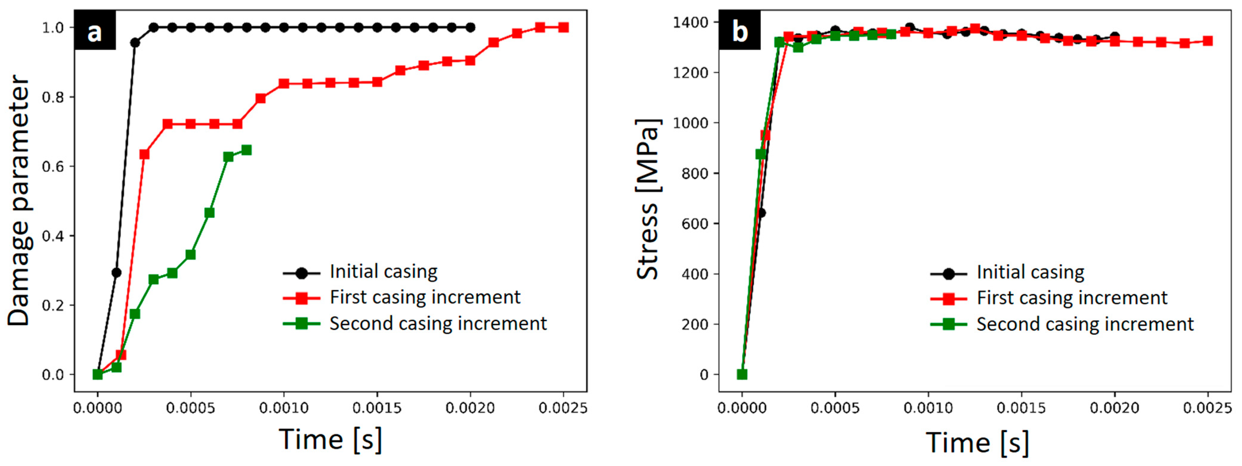
Figure 8 shows the evolution of the damage parameter during the simulation of the initial casing; the casing increased by 23%, and the casing with the second increase in thickness. From the images, it can be seen that by increasing the thickness of the casing, the damage to the casing is delayed during impact. These results are expected since a component can absorb more energy through plastic deformation prior to fracture when it has more mass or substance present. The blade, for its part, takes longer to show damage when compared to the model with the initial or thinner casing. This is because the thinner casing deforms more quickly, fracturing and allowing the blade to impact locally, decreasing its kinetic energy by absorbing plastic work until failure. This restriction in the movement of the blade increases the damage rate and localizes its distribution, producing premature rupture or separation of the alloy. Finally, this design process and the validated computational tool are proposed to optimize the casing thickness and evaluate impact interaction for new safe and lightweight turbofan designs.
3.4. Limitations and Future Research Directions
This developed innovative tool for the preliminary structural engineering design of turbofan engine demonstrates that a more accurate model than those existing in the literature has been achieved. The originality and contribution of the new identified Ti64 model reported by Tuninetti et al. in 2024 [35] and the current study of the turbofan FE model include all the aspects suggested by previous research regarding recommendations for improvements in modeling a fan blade out (FBO) event in terms of structural integrity of casing material [55]. Other aspects, such as the specific vibration-based analysis [56], which are not covered in the present study could provide more insights to determine dynamic loads transferred to the engine mount and aircraft wing structure. Severe loads induced by FBO due to the sudden imbalance are recommended for a complete structural design [46]. Another important focus is the effect of the turbofan explosion on the low- and high-pressure compressors [57,58], which can generate other types of engine damage or collateral damage that risk the integrity of the aircraft, as well as induced failures due to vibrations and blade fatigue [59] that would modify the simulated impact dynamics. However, these design approaches are beyond the scope and objectives of this reported study.
It should be noted that the deformation behavior of the blades obtained by the model presented here is not exact due to alloy characteristics and processing technology. Anisotropy or the asymmetric tension–compression [31,54] response are factors that could slightly affect the impact resistance of the case. These phenomena and differences between the alloy responses not considered in this study and material model must be estimated and included by design engineering when establishing the safety factor of the components.
In particular, this work contributes to aerospace design and structural integrity. In order to meet the structural conditions of certification required for a safe design based on containment testing, the numerical tool generated and presented for the turbofan, based on the Johnson–Cook damage–plasticity material model of Ti64, enables the reduction in both trial and error and production costs of new aircraft engine prototypes in the preliminary design stage.
In order to advance the design and optimization of aerospace components, it is necessary to highlight the implications of the proposed computational mechanics approach for the safe design of aircraft engine components subjected to impact loading. This also includes the optimization of manufacturing processes associated with the Ti64 alloy parts or other strain rate sensitive materials and applications [12,60] subjected to impact loading or critical components at risk of failure. Accurate prediction of local damage and programmable plastic deformation are essential to determine appropriate design safety factors for critical components not only for engine parts such as the case and fan blade, but also fasteners, brackets, compressor blades, disks, springs, and hydraulic system elements. Plastic deformations vary with strain rate and temperature; these effects considered in the proposed approach can accurately predict dynamic loads and deformations within calibration ranges [34,54]. The computational mechanics and the implemented finite-element-based numerical simulations can enable efficient optimization through virtual testing and custom design, while reducing trial-and-error testing.
4. Conclusions
The three-dimensional computational model of a turbofan has been successfully validated for designing new engines that meet certification requirements under the blade containment test. The simulation of the turbofan based on Johnson–Cook plasticity and damage displayed realistic impact dynamics observed in real conditions. This qualitative validation supports the use of the current reported model for designing new aircraft engines meeting certification requirements for safe, damage-tolerant designs.
Regarding the comparison of results provided by the two Johnson–Cook plasticity and damage models available in the literature for the same Ti64 material, the following statements can be obtained:
- A significant difference was found between the equivalent stress and equivalent plastic strain results obtained through simulation with the parameters identified in this work and the parameters reported by P. Verleysen and J. Peirs, 2017 [43].
- The results demonstrate that there is no single set of parameters for the same material. They will depend on the reference strain rate and the range of strain rates and/or temperatures used in the identification. However, the validity of the parameters is mainly based on the ability of the fitted model to predict the initial yield stress at high speeds. In the case of the Ti64 alloy studied, it is above 1200 MPa, which is correctly modeled by the results provided in the simulations with the data identified in the work of Tuninetti et al. in 2024 [35].
Regarding the simulation of the blade containment test:
- The model developed for the simulation is realistic since it presents the same impact dynamics observed in a real blade containment test. This qualitatively validates the model generated for the design purpose of a new aircraft engine that meets the structural conditions required for a safe, damage-tolerant design.
- The simulations with thickness variation and consequent adaptation of the casing topology allowed us to find a damage-tolerant turbofan model, absorbing the kinetic energy of the blade during the impact and transforming it into plastic deformation work energy without fracture. The proposed design process allows the thickness of the turbofan casing to be optimized until a lightweight and safe structural design is achieved.
Current research focuses on the rotordynamics analysis and modeling of the full turbofan engine including low-pressure and high-pressure compressors under containment test conditions.
Author Contributions
Conceptualization, V.T.; methodology, V.T.; software, H.S.; validation, H.S. and V.T.; formal analysis, V.T. and H.S.; investigation, V.T. and H.S.; resources, V.T.; data curation, H.S.; writing—original draft preparation, V.T. and H.S.; writing—review and editing, V.T.; supervision, V.T.; project administration, V.T. All authors have read and agreed to the published version of the manuscript.
Funding
This research received no external funding.
Data Availability Statement
Dataset available on request from the authors.
Conflicts of Interest
The authors declare no conflicts of interest.
References
- Nasr, M.; Moffat, T. A Design Methodology for Fan Blade-off Based on Structural Failure. In Proceedings of the 19 Conference ISABE, Montreal, QC, Canada, 11–13 November 2009; pp. 1–6. [Google Scholar]
- Yang, B. Blade containment evaluation of civil aircraft engines. Chin. J. Aeronaut. 2013, 26, 9–16. [Google Scholar] [CrossRef]
- He, Z.; Xuan, H.; Bai, C.; Song, M.; Zhu, Z. Containment of soft wall casing wrapped with Kevlar fabric. Chin. J. Aeronaut. 2019, 32, 954–966. [Google Scholar] [CrossRef]
- Valenzuela, M.; Leiva, J.; Salas, A.; Ciudad, G.; Cárdenas, J.P.; Oñate, A.; Hunter, R.; Attia, S.; Tuninetti, V. CEBs with GRC: Fabrication, characterization, modeling, and correlation with microstructural fracture features. Mater. Today Commun. 2023, 37, 107028. [Google Scholar] [CrossRef]
- Rojas-Ulloa, C.; Morch, H.; Tuninetti, V.; Duchêne, L.; Habraken, A.M. Implementation of a modified Graham-Walles viscosity function within a Chaboche viscoplastic constitutive model. Comput. Math. Appl. 2024, 155, 165–175. [Google Scholar] [CrossRef]
- Valdivia, I.; Canales, C.; Tuninetti, V.; Flores, P.; Medina, C. Numerical Prediction of Failure in Unidirectional Fiber Reinforced Composite. Int. J. Appl. Mech. 2021, 13, 2150073. [Google Scholar] [CrossRef]
- Bustos, F.; Hinojosa, J.; Tuninetti, V. Computational Comparison of Performance of Different Steel Plate Shear Yielding Dampers. Buildings 2023, 13, 793. [Google Scholar] [CrossRef]
- Tuninetti, V.; Habraken, A. Impact of anisotropy and viscosity to model the mechanical behavior of Ti–6Al–4V alloy. Mater. Sci. Eng. A 2014, 605, 39–50. [Google Scholar] [CrossRef]
- Saavedra Flores, E.I.; Murugan, M.S.; Friswell, M.; De Souza Neto, E.A. Multi-scale constitutive model for a wood-inspired composite. Procedia Eng. 2011, 10, 3616–3621. [Google Scholar] [CrossRef]
- Guzmán, C.F.; Saavedra Flores, E.I.; Habraken, A.M. Damage characterization in a ferritic steel sheet: Experimental tests, parameter identification and numerical modeling. Int. J. Solids Struct. 2018, 155, 109–122. [Google Scholar] [CrossRef]
- Ahmad, D.; Kumar, D.; Ajaj, R.M. Multiaxial Deformations of Elastomeric Skins for Morphing Wing Applications: Theoretical Modeling and Experimental Investigations. Polymers 2022, 14, 4891. [Google Scholar] [CrossRef]
- Ahmad, D.; Ajaj, R.M. A Multiaxial Fracture of Ecoflex Skin with Different Shore Hardness for Morphing Wing Application. Polymers 2023, 15, 1526. [Google Scholar] [CrossRef] [PubMed]
- Castillo, J.I.; Celentano, D.J.; Cruchaga, M.A.; García-Herrera, C.M. Characterization of strain rate effects in sheet laser forming. Comptes Rendus Mec. 2018, 346, 794–805. [Google Scholar] [CrossRef]
- Morch, H.; Duchêne, L.; Harzallah, R.; Tuninetti, V.; Habraken, A.M. Efficient temperature dependence of parameters for thermo-mechanical finite element modeling of alloy 230. Eur. J. Mech.—A/Solids 2021, 85, 104116. [Google Scholar] [CrossRef]
- Valenzuela, M.; Ciudad, G.; Cárdenas, J.P.; Medina, C.; Salas, A.; Oñate, A.; Pincheira, G.; Attia, S.; Tuninetti, V. Towards the development of performance-efficient compressed earth blocks from industrial and agro-industrial by-products. Renew. Sustain. Energy Rev. 2024, 194, 114323. [Google Scholar] [CrossRef]
- Beltrán, F. Teoría General del Método de los Elementos Finitos; Universidad Politécnica de Madrid: Madrid, Spain, 1998; Available online: https://www.researchgate.net/publication/263926691 (accessed on 15 April 2024).
- Sinha, S.K.; Dorbala, S. Dynamic Loads in the Fan Containment Structure of a Turbofan Engine. J. Aerosp. Eng. 2008, 323, 1–14. [Google Scholar] [CrossRef]
- Sinha, S.K. Rotordynamic analysis of asymmetric turbofan rotor due to fan blade-loss event with contact-impact rub loads. J. Sound Vib. 2013, 332, 2253–2283. [Google Scholar] [CrossRef]
- He, Q.; Xuan, H.; Liu, L.; Hong, W.; Wu, R. Perforation of aero-engine fan casing by a single rotating blade. Aerosp. Sci. Technol. 2013, 25, 234–241. [Google Scholar] [CrossRef]
- Man, M.H.C.; Liu, H.; Low, K.H. Severity assessment of aircraft engine fan blades under airborne collision of unmanned aerial vehicles comparable to bird strike certification standards. Proc. Inst. Mech. Eng. Part G J. Aerosp. Eng. 2022, 236, 1817–1835. [Google Scholar] [CrossRef]
- Johnson, G.R.; Cook, W.H. A constitutive model and data for metals subjected to large strains, high strain rates and high temperatures. In Proceedings of the 7th International Symposium on Ballistics, The Hague, The Netherlands, 19–21 April 1983; pp. 541–547. [Google Scholar]
- Mirzaie, T.; Mirzadeh, H.; Cabrera, J.-M. A simple Zerilli–Armstrong constitutive equation for modeling and prediction of hot deformation flow stress of steels. Mech. Mater. 2016, 94, 38–45. [Google Scholar] [CrossRef]
- Huang, S.; Khan, A. Modeling the mechanical behaviour of 1100-0 aluminum at different strain rates by the bodner-partom model. Int. J. Plast. 1992, 8, 501–517. [Google Scholar] [CrossRef]
- Fameso, F.; Desai, D.; Kok, S.; Newby, M.; Glaser, D. Simulation of laser shock peening on X12Cr steel using an alternate computational mechanical threshold stress plasticity model. Int. J. Adv. Manuf. Technol. 2020, 111, 1–11. [Google Scholar] [CrossRef]
- Nemat-Nasser, S.; Guo, W.-G. Thermomechanical response of HSLA-65 steel plates: Experiments and modeling. Mech. Mater. 2005, 37, 379–405. [Google Scholar] [CrossRef]
- Kotkunde, N.; Deole, A.D.; Gupta, A.K.; Singh, S.K. Comparative study of constitutive modeling for Ti–6Al–4V alloy at low strain rates and elevated temperatures. Mater. Des. 2014, 55, 999–1005. [Google Scholar] [CrossRef]
- Wang, X.; Shi, J. Validation of Johnson-Cook plasticity and damage model using impact experiment. Int. J. Impact Eng. 2013, 60, 67–75. [Google Scholar] [CrossRef]
- Tuninetti, V.; Jaramillo, A.F.; Riu, G.; Rojas-Ulloa, C.; Znaidi, A.; Medina, C.; Mateo, A.M.; Roa, J.J. Experimental Correlation of Mechanical Properties of the Ti-6Al-4V Alloy at Different Length Scales. Metals 2021, 11, 104. [Google Scholar] [CrossRef]
- Rojas-Ulloa, C.; Bouffioux, C.; Jaramillo, A.F.; García-Herrera, C.M.; Hussain, T.; Duchêne, L.; Riu, G.; Roa, J.J.; Flores, P.; Habraken, A.M.; et al. Nanomechanical Characterization of the Deformation Response of Orthotropic Ti–6Al–4V. Adv. Eng. Mater. 2021, 23, 2001341. [Google Scholar] [CrossRef]
- Sima, M.; Özel, T. Modified material constitutive models for serrated chip formation simulations and experimental validation in machining of titanium alloy Ti–6Al–4V. Int. J. Mach. Tools Manuf. 2010, 50, 943–960. [Google Scholar] [CrossRef]
- Tuninetti, V.; Gilles, G.; Flores, P.; Pincheira, G.; Duchêne, L.; Habraken, A.-M. Impact of distortional hardening and the strength differential effect on the prediction of large deformation behavior of the Ti6Al4V alloy. Meccanica 2019, 54, 1823–1840. [Google Scholar] [CrossRef]
- Peirs, J.; Verleysen, P.; Van Paepegem, W.; Degrieck, J. Determining the stress–strain behaviour at large strains from high strain rate tensile and shear experiments. Int. J. Impact Eng. 2011, 38, 406–415. [Google Scholar] [CrossRef]
- Tuninetti, V.; Flores, P.; Valenzuela, M.; Pincheira, G.; Medina, C.; Duchêne, L.; Habraken, A.-M. Experimental characterization of the compressive mechanical behaviour of Ti6Al4V alloy at constant strain rates over the full elastoplastic range. Int. J. Mater. Form. 2020, 13, 709–724. [Google Scholar] [CrossRef]
- Tuninetti, V.; Forcael, D.; Valenzuela, M.; Martínez, A.; Ávila, A.; Medina, C.; Pincheira, G.; Salas, A.; Oñate, A.; Duchêne, L. Assessing Feed-Forward Backpropagation Artificial Neural Networks for Strain-Rate-Sensitive Mechanical Modeling. Materials 2024, 17, 317. [Google Scholar] [CrossRef] [PubMed]
- Tuninetti, V.; Sepúlveda, H.; Beecher, C.; Rojas-Ulloa, C.; Oñate, A.; Medina, C.; Valenzuela, M. A Combined Experimental and Numerical Calibration Approach for Modeling the Performance of Aerospace-Grade Titanium Alloy Products. Aerospace 2024, 11, 285. [Google Scholar] [CrossRef]
- Tuninetti, V. Experimental and Numerical Study of the Quasi-Static Behavior of Ti–6Al–4v. Ph.D. Thesis, Univertisé de Liège, Liège, Belgium, 2014. [Google Scholar]
- Peirs, J. Experimental Charcterisation and Modelling of the Dynamic Behaviour of the Titanium Alloy Ti6Al4V. Ph.D. Thesis, Ghent University, Ghent, Belgium, 2012. [Google Scholar]
- Lecarme, L. Viscoplasticity, Damage, and Fracture of Ti-6Al-4V. Ph.D. Thesis, Université catholique de Louvain, Ottignies-Louvain-la-Neuve, Belgium, 2013. [Google Scholar]
- Tao, Z.-J.; Fan, X.-G.; Yang, H.; Ma, J.; Li, H. A modified Johnson–Cook model for NC warm bending of large diameter thin-walled Ti–6Al–4V tube in wide ranges of strain rates and temperatures. Trans. Nonferrous Met. Soc. China 2018, 28, 298–308. [Google Scholar] [CrossRef]
- Gao, S.; Sang, Y.; Li, Q.; Sun, Y.; Wu, Y.; Wang, H. Constitutive modeling and microstructure research on the deformation mechanism of Ti-6Al-4V alloy under hot forming condition. J. Alloys Compd. 2022, 892, 162128. [Google Scholar] [CrossRef]
- Farahani, H.K.; Ketabchi, M.; Zangeneh, S. Determination of Johnson–Cook Plasticity Model Parameters for Inconel718. J. Mater. Eng. Perform. 2017, 26, 5284–5293. [Google Scholar] [CrossRef]
- Johnson, G.R.; Cook, W.H. Fracture characteristics of three metals subjected to various strains, strain rates, temperatures and pressures. Eng. Fract. Mech. 1985, 21, 31–48. [Google Scholar] [CrossRef]
- Verleysen, P.; Peirs, J. Quasi-static and high strain rate fracture behaviour of Ti6Al4V. Int. J. Impact Eng. 2017, 108, 370–388. [Google Scholar] [CrossRef]
- Kay, G.J. Failure Modelling of Titanium 6Al-4V and Aluminum 2024-T3 with the Johnson-Cook Material Model, US Natl. Tech. Inf. Serv. Springfield, Virginia 22161. DOT/FAA/AR (2003) 1–24. Available online: https://www.tc.faa.gov/its/worldpac/techrpt/ar03-57.pdf (accessed on 15 April 2024).
- Zhang, T.; Chen, W.; Guan, Y.; Gao, D. Study on Titanium Alloy TC4 Ballistic Penetration Resistance Part I: Ballistic Impact Tests. Chin. J. Aeronaut. 2012, 25, 388–395. [Google Scholar] [CrossRef]
- Wang, C.; Zhang, D.; Ma, Y.; Liang, Z.; Hong, J. Dynamic behavior of aero-engine rotor with fusing design suffering blade off. Chin. J. Aeronaut. 2017, 30, 918–931. [Google Scholar] [CrossRef]
- Sepúlveda, H.; Valle, R.; Pincheira, G.; Prasad, C.S.; Salas, A.; Medina, C.; Tuninetti, V. Dynamic numerical prediction of plasticity and damage in a turbofan blade containment test. Proc. Inst. Mech. Eng. Part L J. Mater. Des. Appl. 2022, 237, 2551–2560. [Google Scholar] [CrossRef]
- He, Z.; Guo, X.; Xuan, H.; Shan, X.; Fan, X.; Chen, C.; Hong, W. Characteristics and mechanisms of turboshaft engine axial compressor casing containment. Chin. J. Aeronaut. 2021, 34, 171–180. [Google Scholar] [CrossRef]
- FAA (Federal Aviation Administration). 14-Aeronautics and Space, Code Fed. Regul. Annual Ed. 2016. Available online: https://www.govinfo.gov/content/pkg/CFR-2016-title14-vol1/pdf/CFR-2016-title14-vol1-chapI.pdf (accessed on 15 April 2024).
- Wojtyczka, C.; Marshall, A. Fan Case Forturbofan Engine. 2010. Available online: https://patents.google.com/patent/US20100111675 (accessed on 15 April 2024).
- He, Q.; Xie, Z.; Xuan, H.; Liu, L.; Hong, W. Multi-blade effects on aero-engine blade containment. Aerosp. Sci. Technol. 2016, 49, 101–111. [Google Scholar] [CrossRef]
- Tuninetti, V.; Yuan, S.; Gilles, G.; Guzmán, C.F.; Habraken, A.M.; Duchêne, L. Modeling the ductile fracture and the plastic anisotropy of DC01 steel at room temperature and low strain rates. In Journal of Physics: Conference Series; IOP Publishing: Bristol, UK, 2016; Volume 734. [Google Scholar] [CrossRef]
- Guzmán, C.F.; Tuninetti, V.; Gilles, G.; Habraken, A.M. Assessment of Damage and Anisotropic Plasticity Models to Predict Ti-6Al-4V Behavior. Key Eng. Mater. 2015, 651–653, 575–580. [Google Scholar] [CrossRef]
- Tuninetti, V.; Oñate, A.; Valenzuela, M.; Sepúlveda, H.; Pincheira, G.; Medina, C.; García-Herrera, C.; Duchêne, L.; Habraken, A. Characterization approaches affect asymmetric load predictions of hexagonal close-packed alloy. J. Mater. Res. Technol. 2023, 26, 5028–5036. [Google Scholar] [CrossRef]
- Zhang, L.; Li, J.; Kou, Y. Research Status of Aero-Engine Blade Fly-off. J. Physics Conf. Ser. 2021, 1744, 022124. [Google Scholar] [CrossRef]
- Ma, H.; Yin, F.; Tai, X.; Wang, D.; Wen, B. Vibration response analysis caused by rubbing between rotating blade and casing. J. Mech. Sci. Technol. 2016, 30, 1983–1995. [Google Scholar] [CrossRef]
- Sudhir Sastry, Y.B.; Kiros, B.G.; Hailu, F.; Budarapu, P.R. Impact analysis of compressor rotor blades of an aircraft engine. Front. Struct. Civ. Eng. 2019, 13, 505–514. [Google Scholar] [CrossRef]
- Fox, M.R.; Rossey, W.R.; Raguet, M. Fan Blade Fatigue Fractures in CFM56-7B Engines. J. Fail. Anal. Prev. 2023, 23, 1438–1451. [Google Scholar] [CrossRef]
- Bowyer, E.; Krylov, V. Damping of flexural vibrations in turbofan blades using the acoustic black hole effect. Appl. Acoust. 2014, 76, 359–365. [Google Scholar] [CrossRef]
- Gour, S.; Ahmad, D.; Kumar, D.; Ajaj, R.M.; Zweiri, Y. Investigating the Tear Fracture of Elastomeric Skins in Morphing Wings: An Experimental and Computational Study. Int. J. Appl. Mech. 2023, 15, 2350096. [Google Scholar] [CrossRef]
Figure 1.
Mechanical strength of Ti64: (a) strain rate hardening behavior and (b) thermal softening [33,34,35,36,37,38].

Figure 2.
Model of the turbofan used for the simulation of the blade containment test: (a) complete model, (b) embedment in the joint by bolts, (c) displacement condition in the joint of the rotor and shaft, (d) speed condition of the fan that allows rotation, and (e) angular velocity imposed on the fan and the blade that is released.
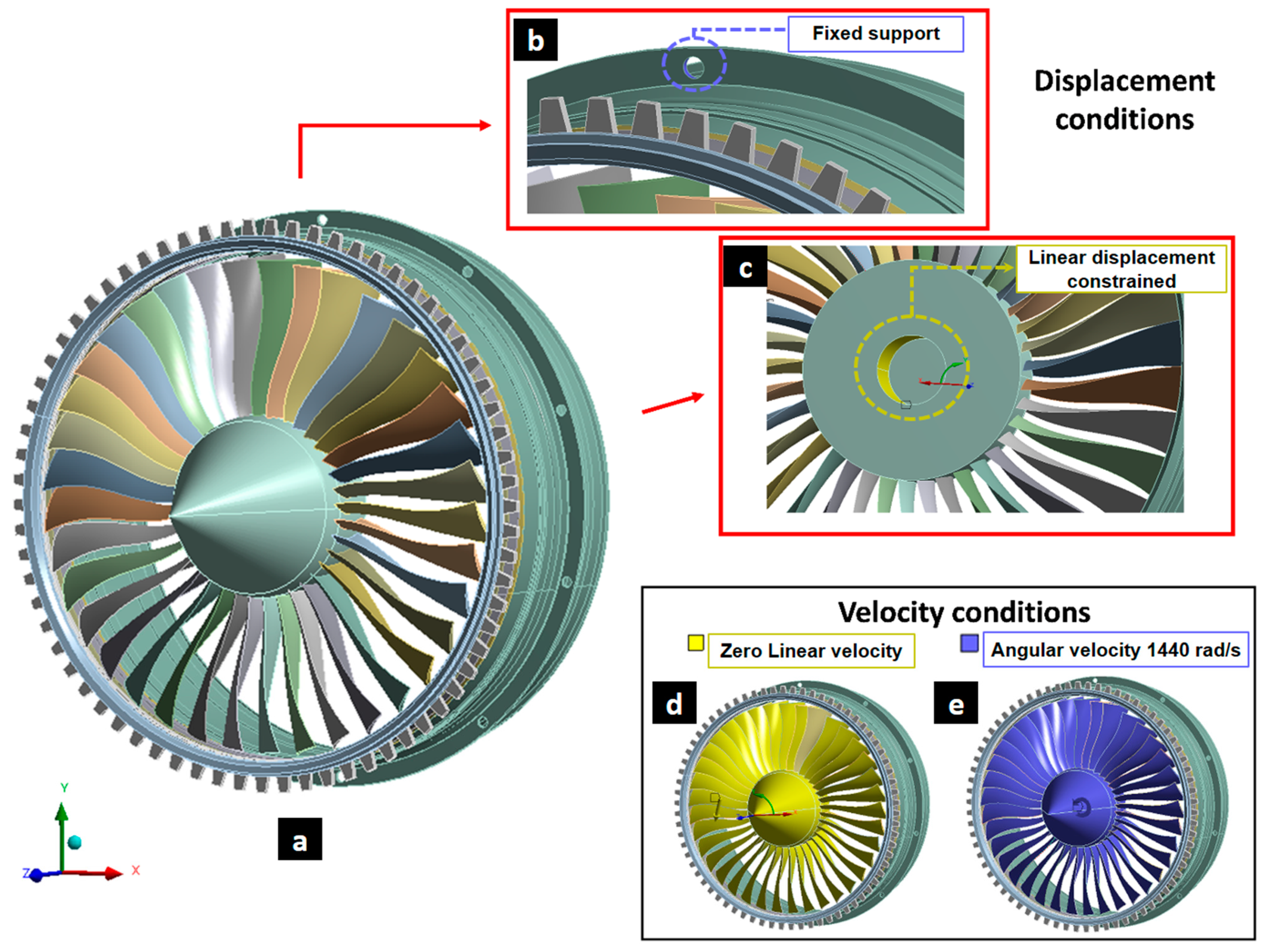
Figure 3.
Meshing of the turbofan engine model for the simulation of the blade containment test: (a) turbofan blades, (b) detached blade, (c) spinner, and (d) casing.
Figure 3.
Meshing of the turbofan engine model for the simulation of the blade containment test: (a) turbofan blades, (b) detached blade, (c) spinner, and (d) casing.
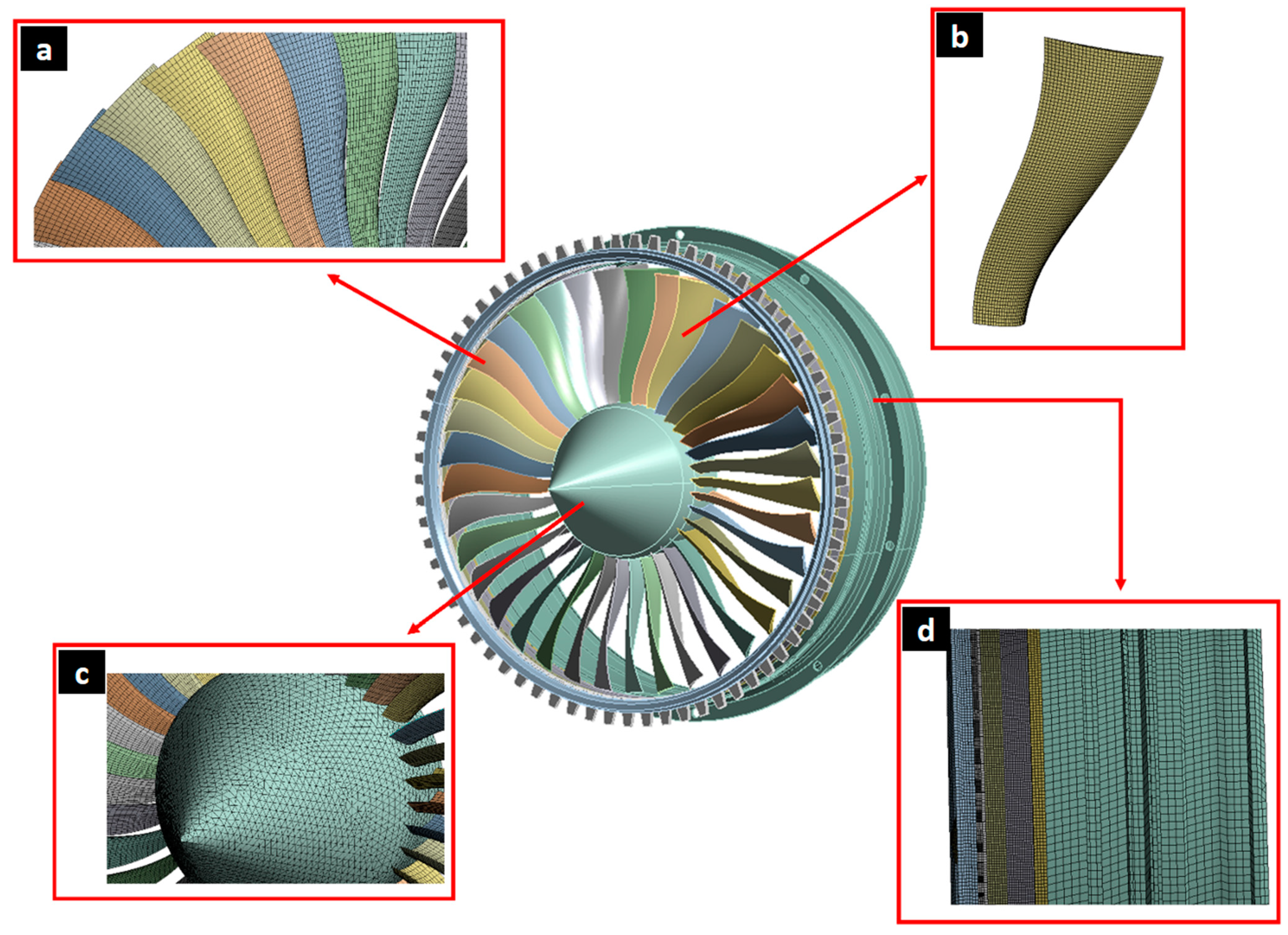
Figure 4.
Comparison between the experimental (a,c,e) and simulated (b,d,f) dynamics of impact during the turbofan blade containment test. (a,b) The detached blade impacts the casing. (c,d) The detached blade impacts the blade rotating behind. (e,f) The detached blade completely impacts both the casing and the blade behind.
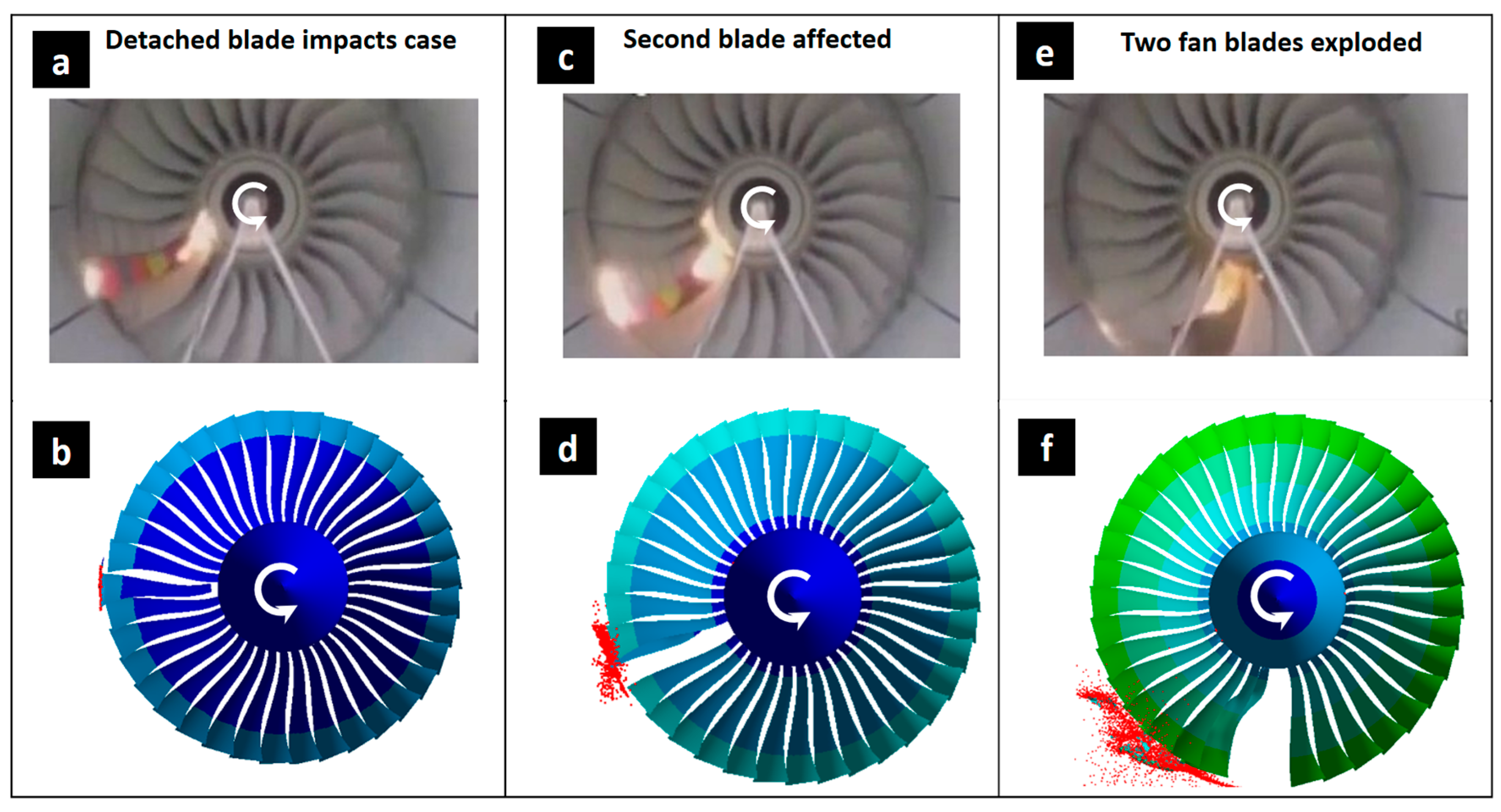
Figure 5.
Results for the distribution of the equivalent stress in all turbofan components obtained through computer simulation: (a) turbofan, (b) blade fragments ejected out of the casing, (c) deformed and fractured casing, and (d) remaining damaged fan.
Figure 5.
Results for the distribution of the equivalent stress in all turbofan components obtained through computer simulation: (a) turbofan, (b) blade fragments ejected out of the casing, (c) deformed and fractured casing, and (d) remaining damaged fan.
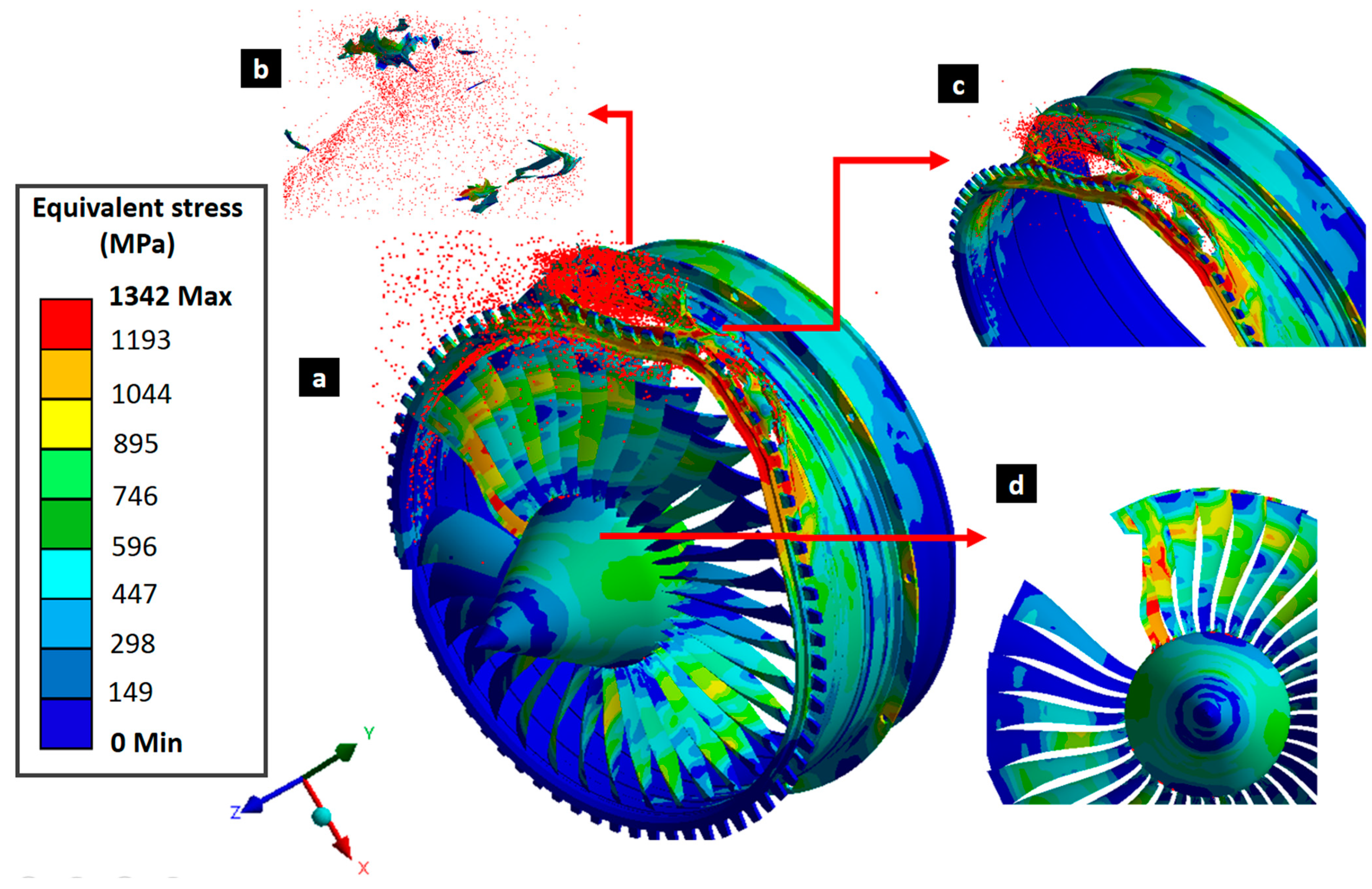
Figure 6.
Drawings of investigated casings: (a) Initial thickness, (b) first variation in increased thicknesses (1st thickness increase), and (c) second variation in casing with increased thicknesses (2nd thickness increase).
Figure 6.
Drawings of investigated casings: (a) Initial thickness, (b) first variation in increased thicknesses (1st thickness increase), and (c) second variation in casing with increased thicknesses (2nd thickness increase).
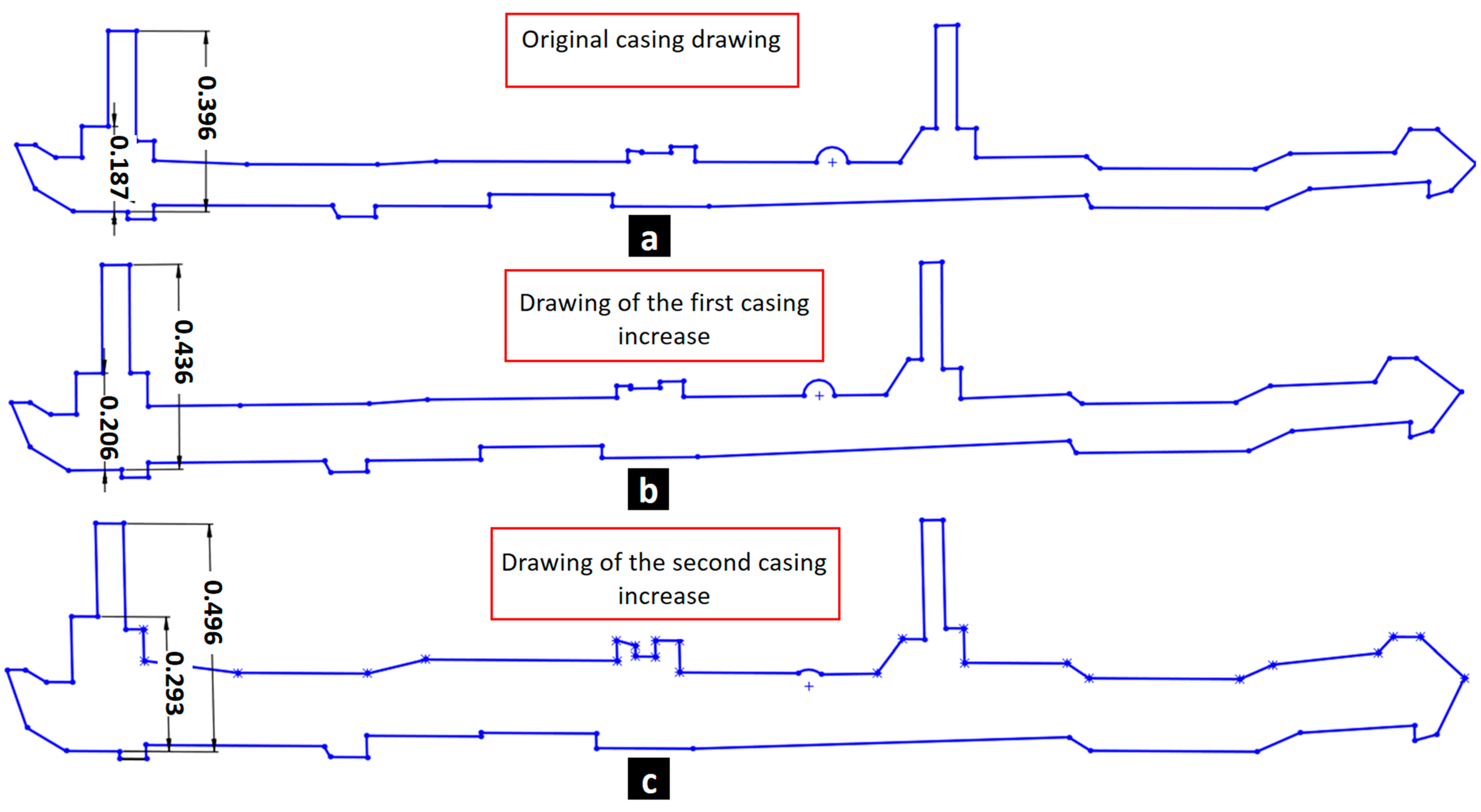
Figure 7.
Von Mises equivalent stress field in (a) initial casing, (b) casing with first thickness increase, and (c) thickest damage tolerant casing.
Figure 7.
Von Mises equivalent stress field in (a) initial casing, (b) casing with first thickness increase, and (c) thickest damage tolerant casing.
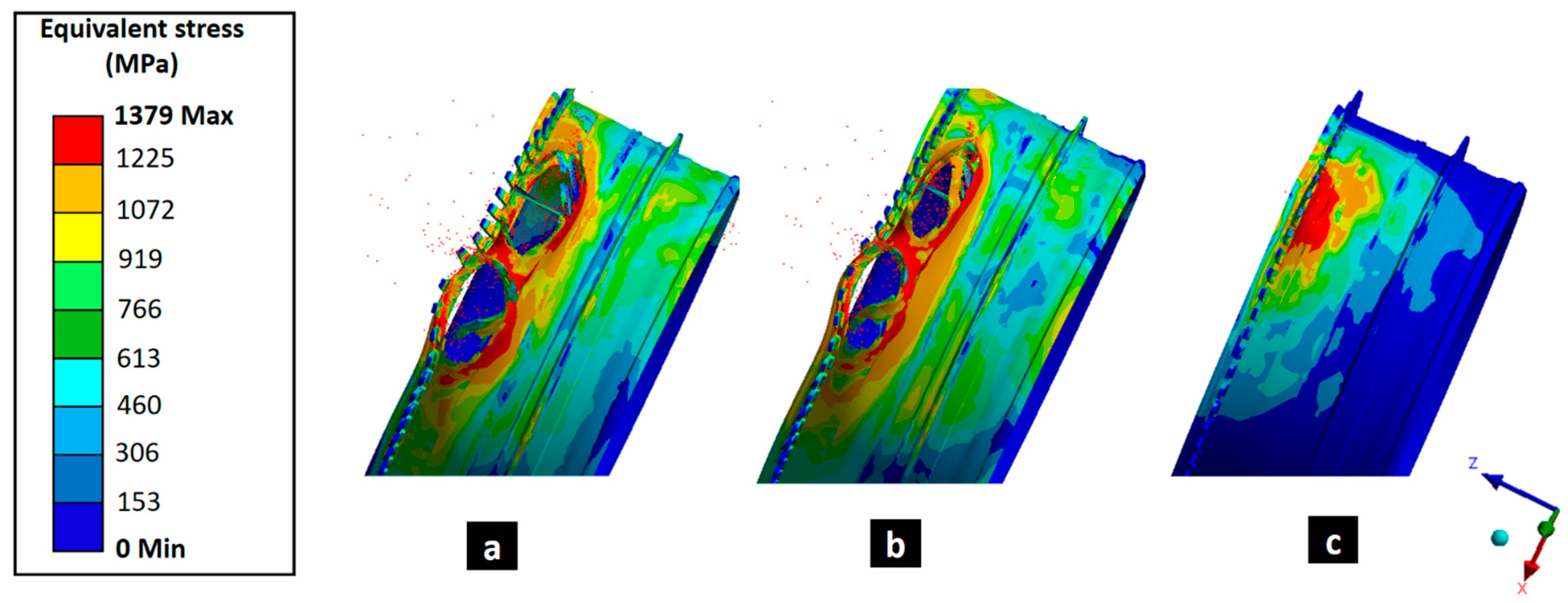
Figure 8.
Evolution of (a) damage and (b) stress during the simulation of the original casing, casing with the first increase in thickness of 23%, and casing with the second increase in thickness containing the explosion.
Figure 8.
Evolution of (a) damage and (b) stress during the simulation of the original casing, casing with the first increase in thickness of 23%, and casing with the second increase in thickness containing the explosion.

Table 1.
Chemical composition of the investigated Ti-6Al-4V (Ti64) alloy [28] in accordance with ISO 5832-3 (4.7 < Al < 7 and 3 < V < 5).
Table 1.
Chemical composition of the investigated Ti-6Al-4V (Ti64) alloy [28] in accordance with ISO 5832-3 (4.7 < Al < 7 and 3 < V < 5).
| Al | V | Fe | N | O | C | Ti |
|---|---|---|---|---|---|---|
| 6.1 | 4.0 | 0.3 | 0.05 | 0.2 | 0.08 | Bal. |
Table 2.
Parameters of the plasticity law and Johnson–Cook damage law obtained by two different studies for Ti64.
Table 2.
Parameters of the plasticity law and Johnson–Cook damage law obtained by two different studies for Ti64.
| Parameters | P. Verleysen and J. Peirs (2017) [43] | Tuninetti, Sepúlveda, Beecher et al. (2024) [35] | |
|---|---|---|---|
| Plasticity | A (MPa) | 895 | 927 |
| B (MPa) | 477 | 877.96 | |
| C | 0.011 | 0.0137 | |
| m | 0.86 | 0.594 | |
| n | 0.38 | 0.795 | |
| Damage | −0.078 | 0.246 | |
| 0.282 | 186.0 | ||
| 0.479 | −15.7 | ||
| 0.029 | 0.2582 | ||
| 3.87 | 1.2059 |
Table 3.
Results obtained for equivalent stress, equivalent plastic deformation, and damage parameter through simulation of the blade containment test.
Table 3.
Results obtained for equivalent stress, equivalent plastic deformation, and damage parameter through simulation of the blade containment test.
| Stress (MPa) | Plastic Strain (mm/mm) | Damage Parameter | |
|---|---|---|---|
| Blade | 1369 | 2.324 | 1 |
| Case | 1379 | 1.680 | 1 |
| Fan | 1351 | 0.946 | 0.6035 |
Table 4.
Simulation results of the blade containment test obtained for equivalent stress, equivalent plastic deformation, and damage parameter by with the material model parameters obtained by P. Verleysen and J. Peirs, 2017 [43] and by Tuninetti et al. in 2024 [35].
| Stress (MPa) | Plastic Strain (mm/mm) | Damage Parameter | ||||
|---|---|---|---|---|---|---|
| Tuninetti et al. 2024 [35] | Verleysen and Peirs 2017 [43] | Tuninetti et al. 2024 [35] | Verleysen and Peirs 2017 [43] | Tuninetti et al. 2024 [35] | Verleysen and Peirs 2017 [43] | |
| Blade | 1369 | 967 | 2.32 | 3.44 | 1 | 1 |
| Case | 1379 | 968 | 1.68 | 3.70 | 1 | 1 |
| Fan | 1351 | 962 | 0.95 | 0.37 | 0.603 | 1 |
Table 5.
Equivalent stress, equivalent plastic deformation, and damage parameter obtained through simulation of the blade containment test for the design with initial casing, and two casings with increased thickness (1st and 2nd increase).
Table 5.
Equivalent stress, equivalent plastic deformation, and damage parameter obtained through simulation of the blade containment test for the design with initial casing, and two casings with increased thickness (1st and 2nd increase).
| Stress (MPa) | Plastic Strain (mm/mm) | Damage Parameter | |||||||
|---|---|---|---|---|---|---|---|---|---|
| Initial Thickness | 1st Thickness Increase | 2nd Thickness Increase | Initial Thickness | 1st Thickness Increase | 2nd Thickness Increase | Initial Thickness | 1st Thickness Increase | 2nd Thickness Increase | |
| Blade | 1369 | 1358 | 1350 | 2.324 | 2.204 | 1.554 | 1 | 1 | 0.808 |
| Case | 1379 | 1375 | 1351 | 1.680 | 1.5 | 1.500 | 1 | 1 | 0.647 |
| Fan | 1351 | 1347 | 1342 | 0.946 | 1.467 | 0.570 | 0.604 | 1 | 0.418 |
Disclaimer/Publisher’s Note: The statements, opinions and data contained in all publications are solely those of the individual author(s) and contributor(s) and not of MDPI and/or the editor(s). MDPI and/or the editor(s) disclaim responsibility for any injury to people or property resulting from any ideas, methods, instructions or products referred to in the content. |
© 2024 by the authors. Licensee MDPI, Basel, Switzerland. This article is an open access article distributed under the terms and conditions of the Creative Commons Attribution (CC BY) license (https://creativecommons.org/licenses/by/4.0/).
Share and Cite
MDPI and ACS Style
Tuninetti, V.; Sepúlveda, H. Computational Mechanics for Turbofan Engine Blade Containment Testing: Fan Case Design and Blade Impact Dynamics by Finite Element Simulations. Aerospace 2024, 11, 333. https://doi.org/10.3390/aerospace11050333
AMA Style
Tuninetti V, Sepúlveda H. Computational Mechanics for Turbofan Engine Blade Containment Testing: Fan Case Design and Blade Impact Dynamics by Finite Element Simulations. Aerospace. 2024; 11(5):333. https://doi.org/10.3390/aerospace11050333
Chicago/Turabian StyleTuninetti, Víctor, and Héctor Sepúlveda. 2024. "Computational Mechanics for Turbofan Engine Blade Containment Testing: Fan Case Design and Blade Impact Dynamics by Finite Element Simulations" Aerospace 11, no. 5: 333. https://doi.org/10.3390/aerospace11050333
Note that from the first issue of 2016, this journal uses article numbers instead of page numbers. See further details here.