The Impact of In-Flight Acceleration Environments on the Performance of a Phase-Change Heat Exchanger Unit with Layered Porous Media


1
College of Energy and Power Engineering, Nanjing University of Aeronautics and Astronautics, Nanjing 210016, China
2
College of Astronautics, Nanjing University of Aeronautics and Astronautics, Nanjing 210016, China
*
Author to whom correspondence should be addressed.
Aerospace 2024, 11(5), 335; https://doi.org/10.3390/aerospace11050335
Submission received: 22 January 2024
/
Revised: 17 April 2024
/
Accepted: 19 April 2024
/
Published: 24 April 2024
Abstract
:The Phase-Change Heat Exchanger Unit in Layered Porous Media (PCEU-LPM) is obtained through frozen pouring processing, and exhibits characteristics such as high thermal conductivity, high latent heat, and high permeability, making it suitable for dissipating heat in airborne electronic devices. This study numerically investigates the impact of aircraft speed acceleration conditions, which lead to weightlessness or overload, on the performance of the PCHEU-LPM, with a particular focus on the influence of natural convection in the liquid-phase region. Initially, a microscale thermal analysis model is established based on the Navier–Stokes equation scanning electron micrograph to calculate the effective thermal conductivity and permeability of the PCHEU-LPM under different porosities. Subsequently, these parameters are incorporated into a macroscale thermal analysis model based on Darcy’s law, employing an average parameter approach. Using the macroscale thermal analysis model, temperature and velocity fields are computed under various porosities, acceleration magnitudes, and directions. The calculation results indicate that as the acceleration increases from α = 0 to α = 10 g, the interface temperature of the PCHTU-LPM decreases by approximately 5.2 K, and the temperature fluctuation decreases by 2.4 K. If the porosity of the PCHTU-LPM is increased from ε = 70% to ε = 85%, the influence of acceleration change on natural convection will be further amplified, resulting in a decrease in the interface temperature of the PCHTU-LPM by approximately 10.2 K and a decrease in temperature fluctuation by 5.8 K. When the acceleration direction is +z, the interface temperature of the PCHTU-LPM is at its lowest, while it is highest when the acceleration direction is −z, with a maximum difference of 15.4 K between the two. When the acceleration direction is ±x and ±y, the interface temperature lies between the former two cases, with the interface temperature slightly higher for ±y compared to ±x, with a maximum difference of 3.9 K between them.
1. Introduction
Phase-change materials, characterized by their cleanliness, environmental friendliness, and recyclability, are well suited for controlling temperature fluctuations in electronic devices due to their high latent heat. Among various phase-change forms, solid–liquid phase change is particularly advantageous owing to its low phase-change temperature and minimal volume change, making it suitable for encapsulation as a temperature control element. This application has found widespread use in the thermal management of electronic devices [1]. Historically, the majority of solid–liquid PCM exhibited extremely low thermal conductivity (0.1–0.7 W/m·K), limiting their transient thermal management capabilities as only a small fraction of PCM could undergo melting. In response, researchers have proposed numerous methods to enhance the heat transfer performance of phase-change materials, including the incorporation of metal fins [2], expanded graphite [3], phase-change microencapsulation [4] nanofluid phase-change materials [5], and topologically optimized metal structures [6]. Notably, the effective combination of phase-change materials with porous media with high thermal conductivity has emerged as a compelling approach to augmenting PCM thermal performance [7]. The metal-based substrate of porous media exhibits high thermal conductivity, and its characteristics of small pore size and large porosity causes it to enlarge the heat transfer area significantly. This, in turn, enhances the energy storage density of the composite material. Moreover, the uniform distribution of porous media contributes to the uniformity of the temperature field.
Beckermann et al. [8] conducted experimental and numerical investigations on phase-change heat transfer within porous media, revealing that the process is influenced by natural convection in the melting zone and solid-phase heat conduction, with the impact of natural convection being non-negligible. However, Tian et al. [9] observed in their study that natural convection in the liquid region of the composite material is inhibited by porous media. This inhibition is attributed to the high viscosity and low thermal expansion ratio of phase-change materials, as well as the significant flow resistance of metal foam, resulting in weak buoyancy-driven velocities insufficient to generate convection. Mesalhy et al. [10] conducted numerical studies on the melting of PCM-porous matrix composite materials, emphasizing the substantial impact of porous matrix material selection on heat transfer rates. Li et al. [11] investigated natural convection melting of paraffin in metal foam through experiments and numerical analyses, providing a visualization of the phase field. Xu et al. [12], employing theoretical analysis and numerical simulation methods, compared the influence of the presence or absence of porous media on the heat transfer performance of the composite material. They assessed the impact of design parameters such as pore size, porosity, and matrix thermal conductivity on heat transfer rates. Yao et al. [13] conducted simulation comparisons of two methods for constructing thermal models involving porous media and phase-change composites. The results indicated that, compared to the average parameter method, the variation trends of natural convection in the heat transfer process were better characterized by the enthalpy-porosity method.
Due to the intricate internal structure of porous media and the diminutive size of pore structures, visualizing changes in the phase field through experimental means becomes challenging. Consequently, numerous studies, motivated by these challenges, opt for numerical methods, and this research aligns with this practice. However, the prevailing literature on phase-change heat transfer in porous media often assumes a uniformly random distribution of porous structures resembling a sponge-like morphology. Yet, according to the findings of Gómez-Martín et al. [14], the heat transfer performance of porous media is directly correlated with the parameter of curvature, where smaller curvature results in enhanced permeability and thermal conductivity. In light of this, the freeze casting method [15] can yield a layered porous media morphology with minimal curvature, favoring both heat conduction and natural convection. Despite the potential benefits with the good heat transfer performance of this new composite material, research in this domain is notably scarce. To address this gap, this study primarily investigates the impact of aircraft acceleration variations on the performance of PCHEU-LPM. This research not only offers valuable insights into understanding phase-change thermal management systems in airborne acceleration environments but also holds potential implications for the design and optimization of heat exchange units in the aerospace engineering context.
This study begins by establishing a simplified microscopic-scale geometric model based on scanning electron microscope (SEM) images of the PCHEU-LPM. This model incorporates independently structured porous media skeletons and void structures filled with phase-change material. Employing steady-state calculations, the permeability and effective thermal conductivity of the PCHEU-LPM are determined for porosities of 70% and 85%. Subsequently, these obtained permeability and effective thermal conductivity values are incorporated into a macroscale heat transfer model based on the average parameter method. This study investigates the temperature fields and phase fields under complex boundary conditions in different gravity airborne acceleration environments. Finally, by comparing the heating interface temperature curves of the PCHEU-LPM, the thermal control performance is assessed under various acceleration conditions. This study aims to provide insights into the potential applications and scope of this novel composite material combining layered porous media with phase-change materials, while also evaluating the natural convection characteristics of this new material under acceleration environments.
2. Theoretical Models and Numerical Solution Methods
This study addresses issues related to the composite modeling of porous media and phase-change materials, coupled heat transfer processes involving phase change and heat exchange, as well as the modeling of both microscopic and macroscopic scales. Two distinct thermal models are developed to tackle these challenges. Given the highly nonlinear nature of the phase-change process in phase-change materials, where thermal flow encounters discontinuities at the phase interfaces, and the complexity is further heightened by the simultaneous occurrence of heat absorption and release during the heat exchange process, numerical solutions are imperative for analysis. On the other hand, the layered porous media obtained through the freeze casting method exerts a microscale influence on the heat transfer and flow characteristics of phase-change materials.
In order to understand the heat transfer characteristics and flow behavior of the PCHEU-LPM at the microscale, it is necessary to model the heat transfer between the metal porous medium and PCM filler and the flow of the liquid PCM based on its local microscopic morphology using the enthalpy-porosity model. From the macroscopic perspective, the actual volume of the PCHEU-LPM far exceeds the microscale (by over 5000 times). For a specific research task, it is impractical to fully obtain and simulate the microscopic morphology characteristics at every location inside the material. Therefore, the effective thermal conductivity and permeability obtained from the microscopic model need to be used as key parameters and input into the macroscopic model as average parameters, which are then employed to construct a three-dimensional macroscopic model using Darcy’s law. Finally, the consistency of the microscopic and macroscopic numerical models is verified through the calculation results of the temperature and flow fields.
2.1. Heat Transfer Process
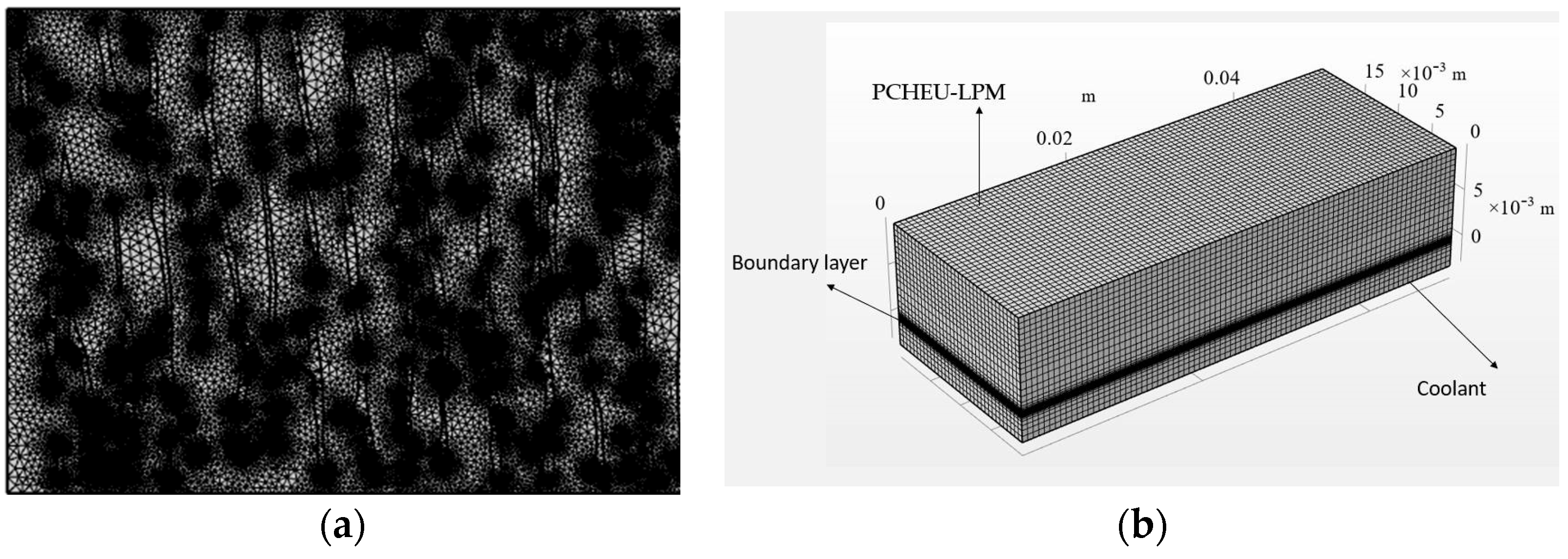
The composite material, consisting of porous media and phase-change materials, is regarded as a whole, serving as the base material for the heat exchange unit embedded in the thermal management system. The skeleton of the porous medium consists of copper powder, while the PCM is paraffin. The PCHEU-LPM is a rectangular prism measuring 40 mm × 12 mm × 7 mm, as shown in Figure 1a. Its initial temperature is 320 K. A pulsed heat flux is uniformly applied to its top surface, with a pulse oscillation period of 50 s, a duty cycle of 50%, and an amplitude of 80,000 W/m2. The bottom surface of the PCHEU-LPM acts as a heat dissipation surface, exchanging heat with a cold fluid. The cold fluid is water, with a constant temperature of 293 K. The convective heat transfer coefficient h between the PCHEU-LPM and water is 1500 W/m2·K, and the convective heat transfer coefficient is uniformly distributed on the surface. Except for the top and bottom surfaces, the remaining four surfaces of the PCHEU-LPM are adiabatic. Assuming the PCHEU-LPM is precisely in the phase-change process, it transitions from the liquid-phase region at the top to the solid-phase region at the bottom, passing through the two-phase region. The heat transfer process of the two-dimensional cross-section along the heat transfer direction is illustrated in Figure 1b, where represents the phase-change temperature, and the dashed line indicates the phase interface.
2.2. Microscopic Scale Heat and Mass Transfer Model
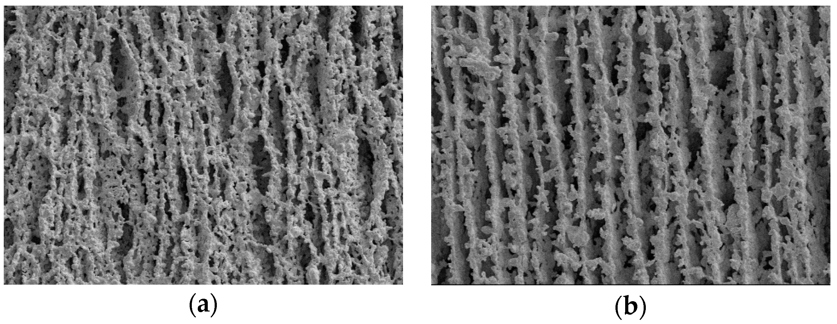
Based on the captured SEM images serving as local morphology features, the PCHEU-LPMs with porosities of 70% and 85% were investigated separately. The dimensions of these microscopic images are 1.8 mm × 1.24 mm, as depicted in Figure 2. The two-dimensional contour features of the microscopic images were extracted using the medical modeling software Mimics 21. Based on these two-dimensional contour features, further simplification was conducted using BricsCad V22 to reduce the complexity of contour curves while ensuring consistency with the actual object’s porosity. The final geometric model imported into finite element software is illustrated in Figure 3.
2.2.1. Governing Equations for Metal Porous Medium
The governing equation for heat transfer in a porous medium framework involves several assumptions that need to be considered before constructing the model. These assumptions are as follows:
- (1)
- The skeletal material is copper with a thermal conductivity of 385 W/m·K.
- (2)
- The porous medium is isotropic in all directions.
- (3)
- The pore density is uniform, and the porosity remains constant.
The heat transfer within the copper framework is expressed through the energy balance equation, as illustrated by Equation (1):
2.2.2. Governing Equations for PCM
Prior to constructing the thermal and mass transfer model for phase-change materials, the following assumptions are made:
- (1)
- The phase-change material is paraffin, a pure substance, with a thermal conductivity of 0.558 W/m·K and a latent heat of 230 kJ/kg.
- (2)
- The internal structure of the phase-change material is isotropic.
- (3)
- After melting, the phase-change material exhibits laminar flow, is incompressible, and features a mushy zone during the phase-change process.
- (4)
- The material properties of paraffin remain constant in the solid and liquid phases, independent of temperature, while exhibiting linear variations in the mushy zone.
- (5)
- Post-melting, paraffin adheres to the Boussinesq assumption, wherein density changes affect only the volume force term in the momentum equation.
- (6)
- The influence of surface tension is neglected.
In accordance with these assumptions, continuous equations, momentum equations, and energy equations are established to elucidate the thermal and mass transfer processes of the phase-change material. The continuity equation is given by:
The momentum equation is given by:
In the above expression, the buoyancy force influenced by gravity only varies in the y direction. Here, represents the dynamic viscosity of the PCM, is the phase-change temperature of the PCM, and , respectively, denote the body force terms in the momentum equation. Their definitions are as follows:
The adjustment of parameter B is aimed at maintaining the significance of the definition when the PCM is in the solid phase. Typically, this value is set to a very small number, such as . represents the damping parameter, serving the purpose of ensuring the continuity and momentum equations across the two-phase region. As the liquid phase fraction ε varies from 0 to 1, the value of uniformly changes from .
The energy equation is given by:
2.3. Macroscopic-Scale Heat and Mass Transfer Model
In contrast to the microscopic scale, where separate models are developed for the metal framework and phase-change material and their connection is established through the local non-thermal equilibrium of the energy equation, at the macroscopic level, this study considers the metal framework and phase-change material as an integrated entity. The description employs the volume fraction θ to represent the proportions of the framework and phase-change material individually. The following assumptions are made:
- (1)
- The material properties of the metal framework and phase-change material are isotropic.
- (2)
- The pore density is uniform, and the porosity remains constant.
- (3)
- The phase-change material, post-melting, exhibits laminar flow, is incompressible, and complies with Darcy’s law.
Based on these assumptions, continuity equations, momentum equations, and energy equations are established. The continuity equation is given by:
The momentum equation is given by:
γ is the linear expansion coefficient, which represents the coefficient of change in density of the composite material with temperature variation. F is the coefficient of inertia resistance.
The energy equation is given by:
2.4. Meshing Method
The grid configurations for the microscopic and macroscopic models are illustrated in Figure 4a and Figure 4b, respectively. In Figure 4a, with geometric dimensions of 1.8 mm × 1.24 mm, a free triangular mesh is employed. Grid refinement is applied at the fluid–solid coupling interface, the minimum thickness of the boundary layer is 0.311 μm, resulting in a total of 113,981 grids. The average grid quality is 0.758, and the minimum unit area is 0.223 mm2. In Figure 4b, featuring dimensions of 40 mm × 7 mm, a structured tetrahedral mesh is utilized, comprising 59,210 grids with a grid quality of 1.
The maximum grid size for both the microscale and macroscale models is assessed based on the calculated average liquefaction rate of the PCHEU-LPM to evaluate grid independence. The results are, respectively, illustrated in Figure 5a,b. From Figure 5a, it can be observed that the average liquidation rate ceases to vary when the maximum grid length is ≤0.3 m, thus this value is selected as the maximum size for the grid model. As depicted in Figure 5b, the liquidation rate ceases to change when the maximum grid length is ≤2.5 mm, thus this value is chosen as the maximum size for the grid model.
2.5. Model Verification
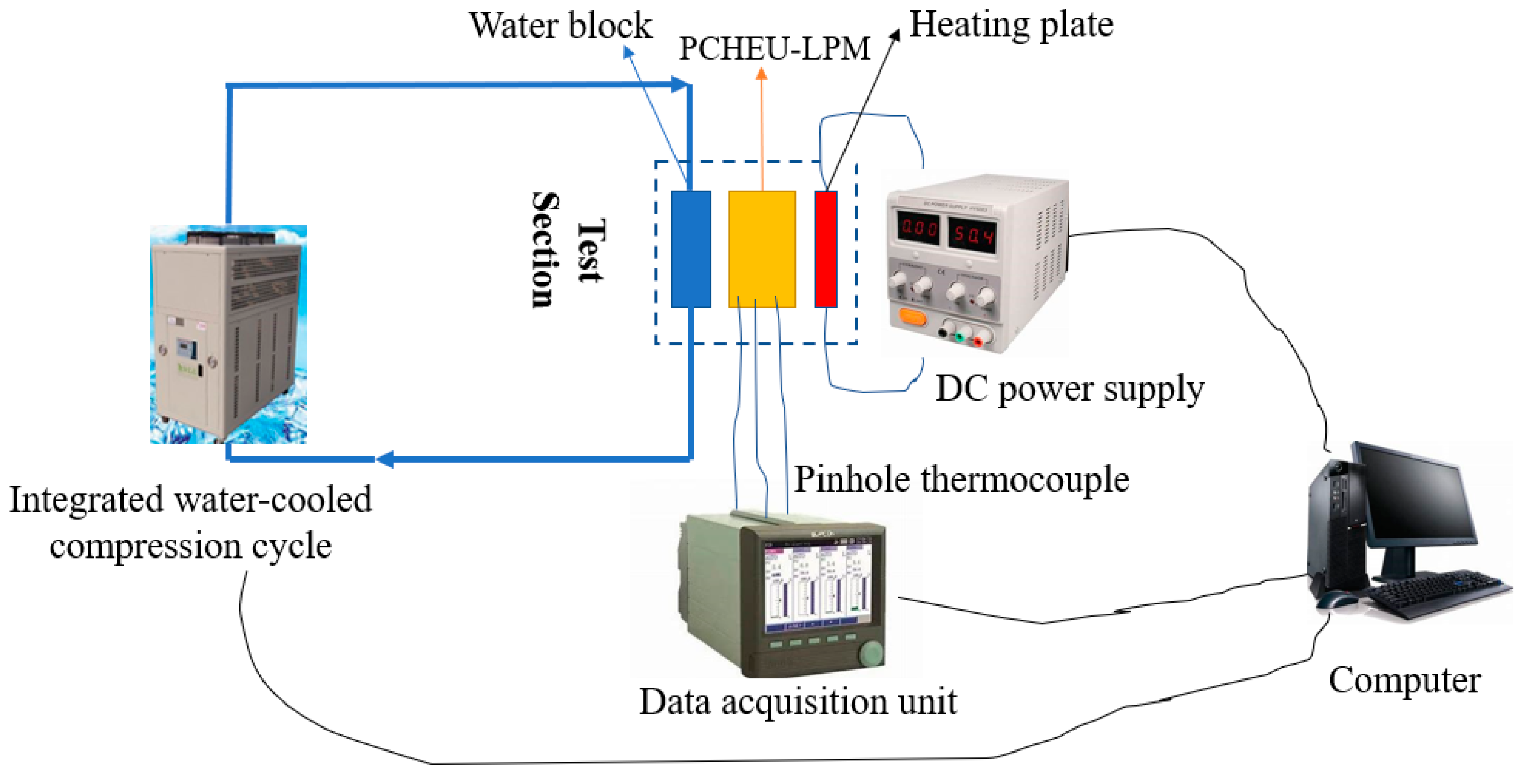
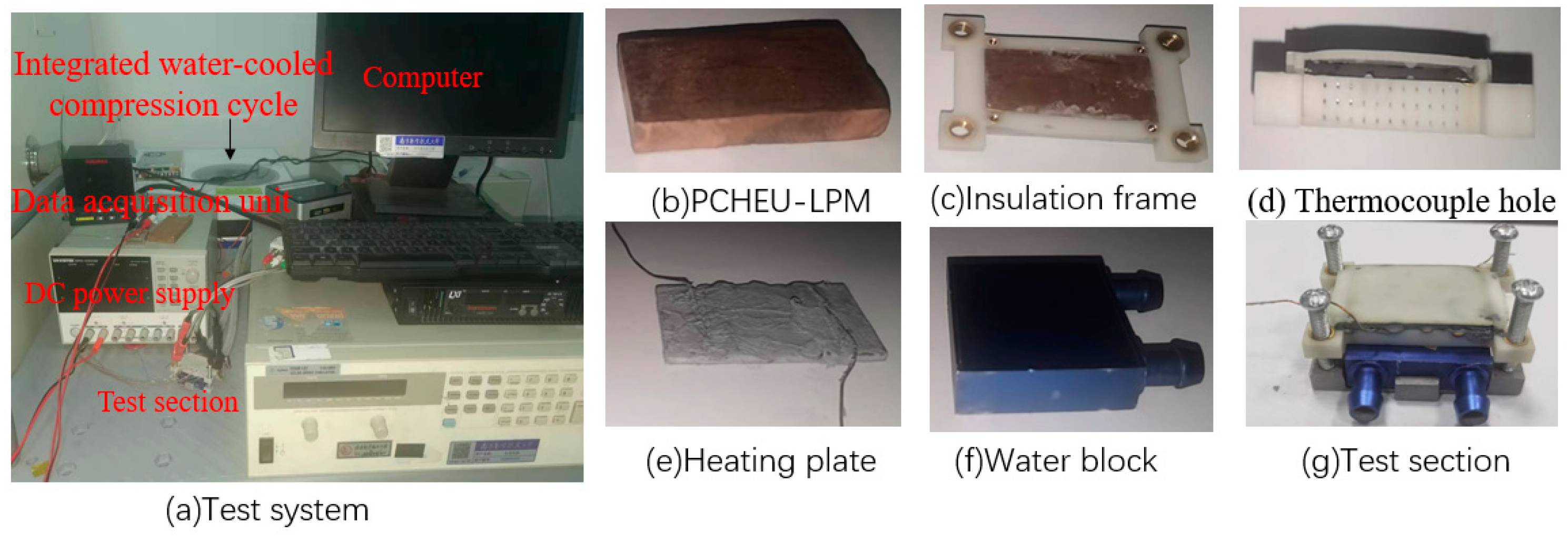
The experimental setup is utilized to validate the aforementioned PCHEU-LPM simulation model illustrated in Figure 6 and Figure 7. In Figure 6, the PCHEU-LPM (depicted in Figure 7b) is thermally interfaced within a water-cooled compression cycle system (depicted in Figure 7a). At the top of the PCHEU-LPM, an aluminum alloy plate, partially embedded with copper wires, serves as the heating plate (depicted in Figure 7e) to simulate a 12 W heat source. This heating plate is connected to a direct current power supply. Surrounding the PCHEU-LPM is a 3D-printed framework (depicted in Figure 7c) designed for insulation, composed of cured silicone rubber material. The framework features 1 mm apertures on one side, allowing for the insertion of nine K-type thermocouples (depicted in Figure 7d). The bottom of the framework is hollowed out and directly connected to a copper water-cooling head through screws (depicted in Figure 7f).
The experiment is set as two heating modes: constant heat flux heating and pulsed heat flux heating. In the constant heat flux heating mode, the heating power is set at 3.22 W, and the heating duration is 600 s. In the pulsed heat flux heating mode, the peak heating power is 6.15 W, the valley heating power is 0 W, the heating duration is 30 s, and the cooling duration is 110 s. The inlet temperature of the water-cooling system is set at 12 °C with an inlet flow velocity of 0.3 m/s. Three temperature measurement points are arranged along the y-direction in the center of the PCHEU-LPM surface, corresponding to y = 0 mm, y = 3.5 mm, and y = 7 mm, respectively. The experimentally measured temperatures are compared with the numerical results, and the comparative results are depicted in Figure 8a,b. As shown in Figure 8, the temperature difference between the experiment and simulation is less than 5%. The temperature discrepancy is minimal on the top heating surface and maximal on the bottom cooling surface, attributed to the instability introduced by the cooling capacity of the water-cooling system being controlled by the compressor speed.
3. Simulation Results and Discussion
3.1. Determination of Equivalent Thermal Conductivity and Permeability
Initially, the PCHEU-LPM samples with pore fractions of 70% and 85% were processed, with a copper porous media and paraffin as the filling PCM. Subsequently, SEM images of dimensions 1.8 mm × 1.24 mm were captured using an electron microscope, as depicted in Figure 2a,b. The simplified geometric models are presented in Figure 3a,b, where blue parts represent the metal porous media, and gray parts signify the pores. Due to the differing transverse and longitudinal configurations in the layered porous structure, the composite thermal conductivity of the framework and PCM varies in each direction. Consequently, a heat flux boundary and an isothermal boundary were applied to the upper and lower, left and right sides of the geometric model, aiming to solve for the equivalent thermal conductivity in different directions.
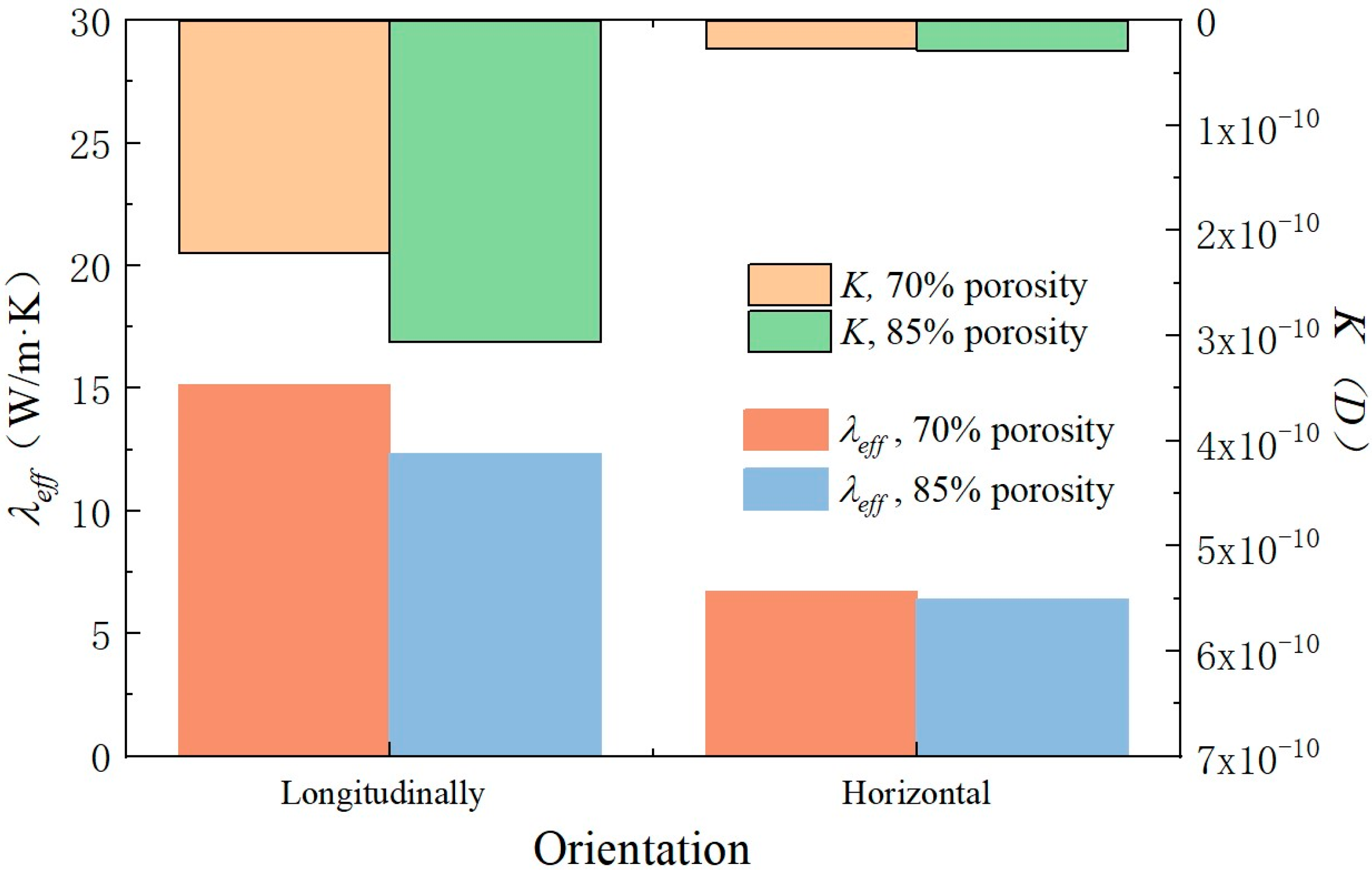
Simulation results yielded corresponding heat fluxes, from which the equivalent thermal conductivity was obtained using Equation (14). The summarized results are presented in Figure 9. It is observed that as the pore fraction increases from 70% to 85%, the longitudinal decreases from 15.2(W/m·K) to 12.3 (W/m·K), while the horizontal remains nearly unchanged. This behavior can be attributed to the layered structure, where longitudinally, the porous media and PCM can be approximated as a parallel circuit, with the total thermal resistance mainly dependent on the proportion of the metal framework. Horizontally, an approximation as a series circuit is suitable, with the total thermal resistance determined by the thermal resistance of the paraffin section.
Subsequently, a pressure boundary with an inlet pressure of 5 Pa was sequentially applied to the upper and left sides of the PCHEU-LPM to determine the outlet velocity gradient and inlet–outlet pressure drop. Using Equation (15), permeabilities in both directions were calculated, and the results are also summarized in Figure 9. It is illustrated in the picture that as the pore fraction increases from 70% to 85%, the longitudinal increases from 2.21 × 10⁻¹⁰ (D) to 3.06 × 10⁻¹⁰ (D), while the horizontal increases from 2.641 × 10⁻¹⁰ (D) to 2.88 × 10⁻¹⁰ (D). Notably, the longitudinal permeability is an order of magnitude greater than the horizontal permeability, and the change in pore fraction has a more significant impact on the longitudinal permeability. This is because the primary flow pathway in the vertically layered porous morphology is from top to bottom, and the variation in pore fraction directly affects the cross-sectional area of the upward and downward channels, thereby influencing the magnitude of permeability.
The above results indicate that the layered morphology structure of the PCHEU-LPM results in significant disparities between the equivalent thermal conductivity, which characterizing heat transfer capability, and the permeability, which representing fluid flow capability, in the longitudinal and transverse directions. Furthermore, altering the pore fraction affects the longitudinal equivalent thermal conductivity and permeability more noticeably, while inducing relatively minor changes in the transverse direction.
3.2. Influence of Acceleration Magnitude on Thermal Performance
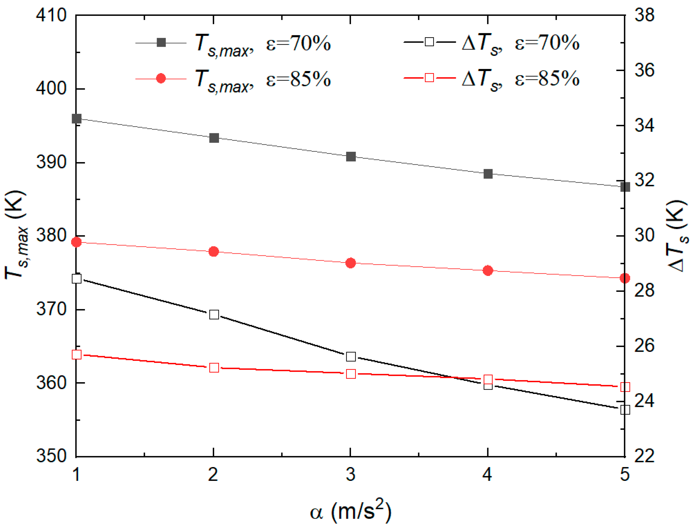
The computed and from Section 3.1 are employed in transient calculations using the macroscopic model. This model is constructed based on the method of average parameters. In the thermal model, the acceleration direction is uniformly assigned as −y, indicating a vertical downward orientation. A pulse heat flux with an amplitude of 8 × 10⁵ W/m2, a pulse period of 100 s, and a duty cycle of 0.5 is applied to the upper side of the thermal model. A constant temperature boundary at 293 K is imposed on the lower side. The initial temperature is set at 320 K, and the total simulation duration is 500 s. To assess the thermal regulation effectiveness of the PCHEU-LPM, the interface temperature at the contact surface with the heating element is captured. The values of for different pore fractions ε and various acceleration magnitudes α are plotted in Figure 10, while the maximum temperature and temperature fluctuation values are illustrated in Figure 11.
From Figure 10 and Figure 11, it can be observed that higher accelerations result in lower interface temperatures of the PCHTU-LPM, indicating better heat dissipation, with a more pronounced trend observed with increasing porosity. As the acceleration α increases from 0 g to 10 g, the highest interface temperature of the PCHTU-LPM with 70% porosity decreases from 381.5 K to 378.9 K, a change of 2.6 K. Similarly, for the PCHTU-LPM with 85% porosity, the highest interface temperature decreases from 399.2 K to 393.7 K, a change of 5.5 K. Moreover, higher accelerations correspond to smaller temperature fluctuations, and the change in temperature fluctuation is more significant with higher porosity. This relationship arises because the acceleration magnitude is positively correlated with the intensity of natural convection. With greater acceleration, the natural convection in the PCM liquid-phase region intensifies, leading to improved internal heat transfer. This causes more PCM to undergo phase change, resulting in increased heat absorption through latent heat, thereby reducing both temperature levels and temperature fluctuations. Additionally, it can be observed from Figure 11 that at the beginning of the PCHTU-LPM heat transfer process, the differences in temperature levels and temperature fluctuations due to acceleration are not significant. However, as the heat transfer process continues, the PCHTU-LPM accumulates more absorbed heat, making the differences in temperature levels and temperature fluctuations due to acceleration more pronounced. This is because a larger porosity implies a higher proportion of PCM, leading to a larger volume ratio of paraffin undergoing natural convection to the metal framework . Therefore, the impact of acceleration changes on the overall internal thermal resistance becomes more significant.
Temperature field contour plots are presented in Figure 12, and velocity field contour plots are depicted in Figure 13. As observed from Figure 12, as the acceleration increases, the heat transfer efficiency of the PCHTU-LPM increases, resulting in lower temperatures. For the PCHTU-LPM with ε = 70%, as α increases from 2 g to 10 g, the temperature at the heated surface at the top decreases by approximately 5.8 K, with the temperature distribution remaining uniformly varied along the direction of heat flow. This indicates that temperature uniformity is insensitive to changes in acceleration magnitude when porosity is lower. For the PCHTU-LPM with ε = 85%, when α increases from 2 g to 10 g, the temperature at the heated surface at the top decreases by approximately 10.2 K, which is higher than that for ε = 70%. This is mainly because a higher proportion of phase-change materials are involved in heat transfer, where the impact of natural convection on heat transfer is more significant, ultimately resulting in higher overall temperatures and a less uniform temperature distribution for the PCHTU-LPM.
As shown in Figure 13, the greater the α is, the faster the flow velocity in the liquid-phase region will appear. For ε = 70%, regardless of how α changes, the velocity field is symmetric along the x and y axes, and large vortices are not formed in the liquid-phase region due to temperature and density differences, but are hindered by the pores, resulting in fragmented vortices at the pore scale, which is particularly evident at α = 10 g. Therefore, uniformly fragmented small vortices only change the intensity of natural convection heat transfer at different accelerations, but hardly alter the spatial temperature distribution. When ε is increased to 85%, the velocity field in the liquid-phase region increases by an order of magnitude, from 10−5 m/s to 10−4 m/s. This indicates that at high porosity, the higher proportion of PCM causes a decrease in the effective thermal conductivity, resulting in higher temperatures, which will lead to more melted PCM, and more vigorous natural convection in the liquid-phase region. Additionally, the heat transfer and flow characteristics of the higher-porosity porous phase-change material are closer to pure substance phase-change materials, and the velocity field distribution is no longer a fragmented vortices at the pore scale, but rather a vortex flow at the macro scale, which becomes more pronounced with increasing acceleration.
The computational results above indicate that the intensification of gravitational acceleration amplifies natural convection heat transfer in the PCHTU-LPM. This effect results in a decrease in interface temperature and temperature fluctuations. Additionally, a higher porosity corresponds to a more pronounced reduction in these parameters. However, within the structured, layered porous medium of the PCHEU-LPM, the PCM is filled into individual small pores, causing the disruption of the velocity vortices into smaller elongated structures. This disruption effectively suppresses temperature non-uniformity induced by natural convection, ensuring that the temperature field in the PCHEU-LPM uniformly varies along the direction of heat flow, irrespective of changes in acceleration magnitude. Considering thermal control aspects, a lower porosity is recommended. One reason is that the PCHEU-LPM with lower porosity exhibits a significantly enhanced heat dissipation effect due to the increased effective thermal conductivity of the composite structure during the heat exchange process. Additionally, the lower-porosity PCHTU-LPM is less influenced by acceleration magnitude, emphasizing its suitability from a thermal management perspective.
3.3. Influence of Acceleration Direction on Thermal Performance
To investigate the impact of varying acceleration directions on the temperature and phase fields of the PCHEU-LPM under identical acceleration magnitudes , the acceleration direction was decomposed into −y, +y, −x, and +x, according to the Cartesian coordinate system, and the interface temperature for different acceleration directions was plotted in Figure 14. It can be observed from the figure that changes in acceleration direction significantly affect the response of the interface temperature. When the acceleration direction is +z, the interface temperature of the PCHTU-LPM is the lowest, while it is the highest when the acceleration direction is −z, with a maximum difference of 15.4 K between the two. When the acceleration direction is ±x and ±y, the interface temperature falls between the former two, slightly higher for ±y compared to ±x, with a maximum difference of 3.9 K between them.
Figure 15 depicts the temperature distribution of PCHTU-LPM at 425 s under different acceleration directions. It can be observed from the figure that changing the acceleration direction will lead to the changes of the distribution of temperature fields along that direction, thereby creating gradients. For instance, when the acceleration direction is +x, the temperature distribution along the x-z plane of the PCHTU-LPM changes from high to low along the +x direction. Conversely, when the acceleration direction is −x, the temperature distribution on the x-z plane is opposite to that of +x. However, the temperature distributions on the y-z plane, which are independent of the x direction, remain almost consistent between the two cases. When the acceleration direction is ±y, the differences in temperature fields are primarily manifested in the y-z plane. Due to the longer length of the PCHTU-LPM structure in the x direction, the larger variation space results in a greater temperature gradient along the x direction when the acceleration direction is ±x compared to when it is ±y.
Figure 16 depicts the velocity distribution of the PCHTU-LPM under different acceleration directions at 425 s and 450 s pulse peak moments. Comparing Figure 15 and Figure 16, it can be observed that the changes in acceleration direction correspond to the changes in velocity field, similar to the changes in temperature distribution. When the acceleration direction is +x, the velocity field changes from high to low along the +x direction. Higher flow velocity leads to greater natural convection heat transfer intensity and lower local temperatures, resulting in a temperature distribution from low to high. This trend is similar for other acceleration directions. With the heat flow direction consistently from top to bottom, when the acceleration direction is opposite to the heat transfer direction (+z), the density difference between the lower and upper temperature regions prompts the upward movement of the lower-temperature fluid and the downward movement of the higher-temperature fluid. However, with the acceleration direction being +z, the buoyant force direction is downward, and the downward buoyant force on the higher-temperature region exceeds that on the lower-temperature region, resulting in a counterforce against fluid movement, ultimately reducing the natural convection heat transfer intensity. The buoyant force is influenced by both the acceleration direction and the density difference caused by temperature variation. When the acceleration direction aligns with the heat transfer direction (−z direction), the buoyant force aligns with the density difference direction, creating a positive circulation, leading to the strongest natural convection heat transfer. When the acceleration direction becomes horizontal (±x, ±y), the density difference caused by the temperature difference between the top and bottom results in a tendency for fluid to flow upward from bottom to top. However, horizontal acceleration generates horizontal buoyant forces, resulting in a secondary flow in the horizontal direction, thus placing the natural convection intensity between +z and −z.
The aforementioned findings indicate a pronounced influence of the acceleration direction on the temperature distribution of the PCHEU-LPM. Specifically, when the acceleration direction is −z, the interface temperature exhibits uniform distribution, resulting in optimal heat dissipation. Conversely, with the acceleration direction being +z, the interface temperature distribution is uniform, but the heat dissipation is least effective. In the case of ±x acceleration directions, there exists an 11.2 K temperature difference between the two ends of the heated surface, and the overall heat dissipation falls between the ranges observed for ±y directions. This finding is crucial for thermal designers when applying PCHEU-LPMs in high Mach number aircraft, where significant interface temperature differences may occur.
4. Conclusions
This paper begins by establishing a simplified microscopic-scale geometric model based on SEM images of the PCHEU-LPM. The model comprises independently characterized structures for the porous medium framework and the pores filled with phase-change material. Employing steady-state calculations, the transverse and longitudinal effective thermal conductivities, along with permeabilities, for PCHEU-LPMs with 70% and 85% porosities are determined. Subsequently, these obtained permeabilities and effective thermal conductivities are incorporated into a macroscopic heat transfer model based on the average parameter method. The study investigates the temperature and phase fields under coupled conditions of pulsed heat boundaries and constant temperature dissipation boundaries, considering various gravitational environments. Finally, by comparing the temperature curves of the heated interface of the PCHEU-LPM, the thermal control performance under different aircraft acceleration conditions is evaluated. Conclusions drawn from microscale and macroscale simulations include the following:
- (1)
- For porous medium morphological structures, layered structures exhibit smaller tortuosity and higher thermal conductivity.
- (2)
- Changes in porosity lead to variations in the equivalent thermal conductivity representing heat exchange capacity and permeability characterizing flow capacity. For layered porous media, porosity primarily alters the longitudinal equivalent thermal conductivity and permeability.
- (3)
- Increasing acceleration magnifies the volume force term in the momentum equation, intensifying the natural convection of the phase-change material.
- (4)
- Higher porosity results in more significant changes in the temperature and phase fields with varying acceleration.
- (5)
- The porous medium structure, impeding natural convection through the framework, breaks down vortices induced by natural convection into smaller vortices, effectively suppressing temperature non-uniformity. This suppression effect improves with increasing gravity.
- (6)
- Heat dissipation is most effective when the acceleration direction aligns with the heat flow direction, is least effective when they oppose each other, and falls between the two in perpendicular alignment.
Author Contributions
Writing-original draft, R.Z.; Writing-review & editing, J.Z. (Jingyang Zhang); Project administration, J.Z. (Jingzhou Zhang). All authors have read and agreed to the published version of the manuscript.
Funding
The authors gratefully acknowledge the financial supports from the National Natural Science Foundation of China (Nos. 51776097 and 52206091), the Aeronautical Science Foundation of China (No. 201928052008), the Natural Science Foundation of Jiangsu Province, China (No. BK20210303), Advanced Jet Propulsion Innovation (Grant No.: HKCX2022-01-001).
Data Availability Statement
The raw data supporting the conclusions of this article will be made available by the authors on request.
Conflicts of Interest
The authors declare no conflict of interest.
Nomenclature
| Parameter name | ||
| Specific heat capacity | J/kg·K | |
| F | Coefficient of inertia resistance | |
| Convective heat transfer coefficient | W/m2·K | |
| Thermal conductivity | W/m·K | |
| K | Permeability | md |
| L | Latent heat of phase change | KJ/kg |
| P | Pressure | Pa |
| Heat flow | W/m2 | |
| Q | Permeation flow rate per unit time | m3/s |
| s | Phase interface location | m |
| Body-force | N/m3 | |
| Temperature | K | |
| X-direction speed | m/s | |
| v | Velocity | m/s |
| Y-direction speed | m/s | |
| Z-direction speed | m/s | |
| ds | Interface distance | mm |
| Greek alphabet | ||
| Acceleration | m/s2 | |
| γ | Linear expansion coefficient | |
| δ | Thickness | m |
| Porosity or liquid phase ratio | ||
| Proportion | ||
| Thermal conductivity | W/m·K | |
| Sport viscosity | Pa-s | |
| Density | Kg/m3 | |
| Time | s | |
| ψ | heat quantity | W |
| Subscript | ||
| 0 | Initial state | |
| c | Cold fluids | |
| eff | equivalent | |
| g | Metal porous medium | |
| l | Liquid phase | |
| m | Phase-change state | |
| Directional vector at the phase interface | ||
| p | PCM | |
| Solid phase | ||
| w | External thermal excitation | |
| Abbreviations | ||
| PCEU-LPM | Phase-Change Heat Exchanger Unit in Layered Porous Media | |
| SEM | Scanning Electron Micrograph | |
| PCM | Phase-change materials |
References
- Butt, N.J.; Wolff, M.; Roberts, R.A.; Thomas, S. A Cryogenic Palletized High Energy Pulse System. In Proceedings of the 2018 International Energy Conversion Engineering Conference, Cincinnati, OH, USA, 9 July 2018; American Institute of Aeronautics and Astronautics: Cincinnati, Ohio, 2018. [Google Scholar]
- Yang, X.; Lu, Z.; Bai, Q.; Zhang, Q.; Jin, L.; Yan, J. Thermal Performance of a Shell-and-Tube Latent Heat Thermal Energy Storage Unit: Role of Annular Fins. Appl. Energy 2017, 202, 558–570. [Google Scholar] [CrossRef]
- Lachheb, M.; Adili, A.; Albouchi, F.; Mzali, F.; Ben Nasrallah, S. Carbon Fiber. Appl. Therm. Eng. 2016, 102, 922–931. [Google Scholar] [CrossRef]
- Alimohammadi, M.; Aghli, Y.; Alavi, E.S.; Sardarabadi, M.; Passandideh-Fard, M. Experimental Investigation of the Effects of Using Nano/Phase Change Materials (NPCM) as Coolant of Electronic Chipsets, under Free and Forced Convection. Appl. Therm. Eng. 2017, 111, 271–279. [Google Scholar] [CrossRef]
- Poplaski, L.M.; Benn, S.P.; Faghri, A. Thermal Performance of Heat Pipes Using Nanofluids. Int. J. Heat Mass Transf. 2017, 107, 358–371. [Google Scholar] [CrossRef]
- Pizzolato, A.; Sharma, A.; Maute, K.; Sciacovelli, A.; Verda, V. Topology Optimization for Heat Transfer Enhancement in Latent Heat Thermal Energy Storage. Int. J. Heat Mass Transf. 2017, 113, 875–888. [Google Scholar] [CrossRef]
- Chen, J.; Yang, D.; Jiang, J.; Ma, A.; Song, D. Research Progress of Phase Change Materials (PCMs) Embedded with Metal Foam (a Review). Procedia Mater. Sci. 2014, 4, 389–394. [Google Scholar] [CrossRef]
- Beckermann, C.; Viskanta, R. Natural Convection Solid/Liquid Phase Change in Porous Media. Int. J. Heat Mass Transf. 1988, 31, 35–46. [Google Scholar] [CrossRef]
- Yun, H.; Fangfang, M.A.; Guo, X.; Chen, B. Mesoscopic Pore-Scale Simulations of Natural Convection of Porous Media in Closed Square Cavity by Using LBM. Procedia Eng. 2017, 205, 4009–4016. [Google Scholar] [CrossRef]
- Mesalhy, O.; Lafdi, K.; Elgafy, A.; Bowman, K. Numerical Study for Enhancing the Thermal Conductivity of Phase Change Material (PCM) Storage Using High Thermal Conductivity Porous Matrix. Energy Convers. Manag. 2005, 46, 847–867. [Google Scholar] [CrossRef]
- Li, W.Q.; Qu, Z.G.; He, Y.L.; Tao, W.Q. Experimental and Numerical Studies on Melting Phase Change Heat Transfer in Open-Cell Metallic Foams Filled with Paraffin. Appl. Therm. Eng. 2012, 37, 1–9. [Google Scholar] [CrossRef]
- Xu, H.; Wang, Y.; Han, X. Analytical Considerations of Thermal Storage and Interface Evolution of a PCM with/without Porous Media. HFF 2019, 30, 373–400. [Google Scholar] [CrossRef]
- Yao, Y.; Wu, H. Numerical Simulation of Melting in Metal Foam/Paraffin Composite Phase Change Material Using a Physically More Reasonable Macroscale Model. In Proceedings of the ASME 2019 Heat Transfer Summer Conference, American Society of Mechanical Engineers, Bellevue, WA, USA, 14 July 2019; p. V001T02A007. [Google Scholar]
- Gómez-Martín, A.; Orihuela, M.P.; Becerra, J.A.; Martínez-Fernández, J.; Ramírez-Rico, J. Permeability and Mechanical Integrity of Porous Biomorphic SiC Ceramics for Application as Hot-Gas Filters. Mater. Des. 2016, 107, 450–460. [Google Scholar] [CrossRef]
- Scotti, K.L.; Dunand, D.C. Freeze Casting—A Review of Processing, Microstructure and Properties via the Open Data Repository, FreezeCasting.Net. Prog. Mater. Sci. 2018, 94, 243–305. [Google Scholar] [CrossRef]
Figure 1.
Schematic diagram of two-dimensional phase-change heat transfer process. (a) Physical model. (b) Cross-sectional heat transfer process.
Figure 1.
Schematic diagram of two-dimensional phase-change heat transfer process. (a) Physical model. (b) Cross-sectional heat transfer process.

Figure 2.
SEM images of PCHEU-LPM with different porosities. Image (a) shows 70% porosity. Image (b) shows 85% porosity.
Figure 2.
SEM images of PCHEU-LPM with different porosities. Image (a) shows 70% porosity. Image (b) shows 85% porosity.

Figure 3.
Two-dimensional simplified geometric model of PCHEU-LPM with different porosities. Image (a) shows 70% porosity. Image (b) shows 85% porosity.
Figure 3.
Two-dimensional simplified geometric model of PCHEU-LPM with different porosities. Image (a) shows 70% porosity. Image (b) shows 85% porosity.

Figure 4.
Schematic diagram of grid division. (a) Microscopic grid model. (b) Macroscopic grid model.
Figure 4.
Schematic diagram of grid division. (a) Microscopic grid model. (b) Macroscopic grid model.

Figure 5.
Grid independence test. (a) Microscopic model. (b) Macroscopic model.

Figure 6.
Experimental setup for the validation of PCHEU-LPM model effectiveness.

Figure 7.
Photographs of components inside the test section.

Figure 8.
Comparison between experimental temperature results and numerical results. (a) Constant heating mode. (b) Pulse heating mode.
Figure 8.
Comparison between experimental temperature results and numerical results. (a) Constant heating mode. (b) Pulse heating mode.

Figure 9.
The equivalent thermal conductivity and permeability of PCHEU-LPM with different porosities.
Figure 9.
The equivalent thermal conductivity and permeability of PCHEU-LPM with different porosities.

Figure 10.
Variation of interface temperature with different acceleration magnitude.

Figure 11.
Variation of maximum temperature and temperature fluctuation values with different acceleration magnitude.
Figure 11.
Variation of maximum temperature and temperature fluctuation values with different acceleration magnitude.

Figure 12.
Contour plots of the temperature field corresponding to different acceleration magnitude. (a) . (b) .
Figure 12.
Contour plots of the temperature field corresponding to different acceleration magnitude. (a) . (b) .

Figure 13.
Schematic diagram of velocity field with different acceleration magnitude. (a) . (b) .

Figure 14.
Variation of interface temperature with different acceleration direction.

Figure 15.
The schematic diagram of temperature field with different acceleration direction.

Figure 16.
The schematic diagram of velocity field with different acceleration direction.

Disclaimer/Publisher’s Note: The statements, opinions and data contained in all publications are solely those of the individual author(s) and contributor(s) and not of MDPI and/or the editor(s). MDPI and/or the editor(s) disclaim responsibility for any injury to people or property resulting from any ideas, methods, instructions or products referred to in the content. |
© 2024 by the authors. Licensee MDPI, Basel, Switzerland. This article is an open access article distributed under the terms and conditions of the Creative Commons Attribution (CC BY) license (https://creativecommons.org/licenses/by/4.0/).
Share and Cite
MDPI and ACS Style
Zhang, R.; Zhang, J.; Zhang, J. The Impact of In-Flight Acceleration Environments on the Performance of a Phase-Change Heat Exchanger Unit with Layered Porous Media. Aerospace 2024, 11, 335. https://doi.org/10.3390/aerospace11050335
AMA Style
Zhang R, Zhang J, Zhang J. The Impact of In-Flight Acceleration Environments on the Performance of a Phase-Change Heat Exchanger Unit with Layered Porous Media. Aerospace. 2024; 11(5):335. https://doi.org/10.3390/aerospace11050335
Chicago/Turabian StyleZhang, Ruoji, Jingyang Zhang, and Jingzhou Zhang. 2024. "The Impact of In-Flight Acceleration Environments on the Performance of a Phase-Change Heat Exchanger Unit with Layered Porous Media" Aerospace 11, no. 5: 335. https://doi.org/10.3390/aerospace11050335
Note that from the first issue of 2016, this journal uses article numbers instead of page numbers. See further details here.