Article

The Development of Rocketry Capability in New Zealand—World Record Rocket and First of Its Kind Rocketry Course

1
Department of Electrical and Computer Engineering, University of Canterbury, Private Bag 4800, Christchurch 8140, New Zealand
2
Rocket Lab Ltd., 3A Airpark Drive, Auckland 2022, New Zealand
3
Department of Mechanical Engineering, University of Canterbury, Private Bag 4800, Christchurch 8140, New Zealand
*
Author to whom correspondence should be addressed.
Aerospace 2015, 2(1), 91-117; https://doi.org/10.3390/aerospace2010091
Submission received: 24 December 2014 / Accepted: 12 February 2015 / Published: 25 February 2015
(This article belongs to the Special Issue Driving Forward Aerospace Innovation)

Abstract

:
The University of Canterbury has developed a rocket research group, UC Rocketry, which recently broke the world altitude record for an I-class motor (impulse of 320–640 Ns) and has run a rocketry course for the first time in New Zealand. This paper discusses the development and results of the world record rocket “Milly” and details all the fundamental elements of the rocketry final year engineering course, including the manufacturing processes, wind tunnel testing, avionics, control and the final rocket launch of “Smokey”. The rockets Milly and Smokey are an example of the design, implementation and testing methodologies that have significantly contributed to research and graduates for New Zealand’s space program.

Graphical Abstract

1. Introduction

There is an emerging demand by the aerospace industry for smaller vehicles to deliver smaller discrete satellites into Low Earth Orbit (LEO). NASA no longer provides LEO launch services; therefore, the private sector is taking up the load and requiring low cost, versatile satellite launch systems to give them a competitive edge.
A University of Canterbury Rocketry Research Group [1] has been developing control systems for small subsonic sounding rockets since 2010. This research is a joint project with Rocket Lab NZ [2] to develop highly flexible control systems that can quickly adapt to new payloads and launch configurations with very minimal testing. Recent work has looked to extend the subsonic rocket systems to transonic and supersonic flight and to further improve the electronics hardware and software on the subsonic rocket to simplify the manufacturing of multiple rockets so that new students can be trained up into the NZ space industry. This paper summarizes two major achievements of UC rocketry in 2014—the development of a small low cost supersonic rocket “Milly” that broke a world altitude record and the successful running of New Zealand’s first rocketry course.
The world record breaking rocket Milly tested a number of new systems including optimized rocket motor designs, tracking and parachute recovery and the use of 3D printing in both canard manufacturing and for testing out the stability of the rocket with smaller motors. The previous world record was set by John Wilke from the US and is one of many classes of records kept by the US amateur rocketry association. John Wilke’s record was for an I-class, single motor that reached a verified altitude of 14,188 ft or 4.32 km on 4 October 2010. These records have helped inspire and motivate students in UC Rocketry to develop better designs and tracking and recovery systems and so is a very useful challenge for new students entering the rocketry field.
UC Rocketry has several former postgraduate students permanently employed in Rocket Lab working on the Electron orbital vehicle [2] and they have been assisting in the development of NZ’s first rocketry course. From 2010 to 2014, UC Rocketry has developed and proven in several launches, accurate 3DOF attitude control via a canard actuation mechanism. This work was part of two Callaghan Innovation Ph.D.’s with Rocket Lab as the industry partner. A detailed history of the development, current state-of-the-art and future work is detailed in [1]. The hardware for this 1.52 m rocket was highly customized, so to allow a more flexible design that could allow more straightforward manufacturing of multiple avionics systems, a new hardware system was developed. Students from this rocketry course helped with the design, implementation and testing of this new system with supervision from UC rocketry [1].
The course started in the second semester of July 2014 and eight students from Mechatronics and Electrical and Computer Engineering were carefully selected. In this course the students have to manufacture and assemble all parts of the rocket, including machining the airframe, motor mounts, parachute and control actuation systems as well as assembling and testing the electronics hardware and software in the vertical wind tunnel. They also get some experience in using 6DOF software and have a lab on designing a 3-stage rocket into orbit using Astos solutions [3], who provided eight academic licenses for this course.
In addition to improving UC rocketry hardware, a further motivation for the course, was to use rocketry as the basis for teaching general skills in instrumentation and sensors, machining and control systems. A major advantage of a rocketry course is that many aspects of engineering are covered all at once, and importantly, the student’s designs must work in an actual launch. This practical outcome requirement greatly motivates students’ and teaches them skills that they wouldn’t normally learn in a typical University course, which is usually focused on theory with practical elements in a lab environment only. Hence, this course is an excellent way of selecting students suitable for carrying on work in the rocketry field with the possibility of entering the NZ space industry in the future. The canard control actuation is a unique feature of this rocketry course and to the authors’ knowledge is the only course available where rocketry is taught with a control focus.
There are a number of examples of university courses and student clubs that are based around or involve an element of rocket development [4,5,6,7,8,9]. However, none involve the design, build and testing of canard-controlled rockets, with the exception of the DARE project team from the Netherlands. DARE has recently begun an advanced canard control project but with no controlled launches as yet and only stable rockets have been considered [9]. Most existing programs are typically small, uncontrolled rockets with an altimeter to validate simple trajectory rocket models [6] or a study into simulation methods with no experimental work [7]. Propulsion systems and aerodynamics are also often the driving force behind university courses and student projects that involve the design and construction of rockets [10,11,12,13]. However, they usually involve theoretical work and are only investigating a specific part of rocketry. Rockets are well recognized as being a fundamental part of teaching science and engineering, yet most courses are taught in a theoretical setting and any laboratories that are run typically involve technicians setting up all the equipment and students only engaging in a limited part of the system. Furthermore, often only the basics are covered with very small off-the-shelf type hobby rockets [14,15,16,17] or water rockets [18].
One quite good example of a program that offers the potential for practical building of rockets is the program STERN run by the German Aerospace Centre [19]. One issue with this program is that nearly all participating teams focus on complex rocket motor developments (mainly hybrid rocket engines) since this is a key research demand for rocketry in Germany. Thus, although the students gain experience with complex propulsion design and project management there is less focus on regular launching of their rockets due to their high complexity [19,20,21,22]. Most of the launches of the STERN program are planned for 2015 in Kiruna (Sweden).
The research in [22] involved one of the authors of this paper (Hans Philipp Sültrop) who was a participant in the STERN project with the team from Braunschweig, but has now come to New Zealand to study under UC Rocketry, due to the limited opportunities to conduct academic research in controlled sounding rockets in Germany and worldwide. Similar to the STERN project there are other projects in Europe like the Polish small sounding rocket program [23]. In France, CNES has a very large budget program and supports for example the project ARES within the PERSEUS project in France [24], which recently successfully launched an uncontrolled supersonic rocket (SERA-1) in Kiruna [25]. However, rocket design and launches in this CNES program are done with significant help of non-students. In the United Kingdom there is the Cambridge Rocketry group CUSF which has had successful rocket flights [26] and in the United States there are a few programs, such as CALVEIN [27,28], but all these projects focus on uncontrolled, highly complex, aerodynamically ballistic rockets with the aim to reach high altitudes.
There is a significant amount of research in the literature that investigates controlled rockets in simulation including supersonic flight [29,30] but there is very little reported on actual rocket flight validation. The approach of UC Rocketry is to use off-the-shelf high-power solid propellant rocket motors and to manufacture simpler robust rocket vehicle designs that have the capability of testing instrumentation, sensors and control algorithms. This philosophy includes minimal modeling of the major rocket dynamics where complexity is only added if it results in a significant improvement to the rocket response and an increased understanding of the major mechanisms involved [31].

2. Methodology

This section outlines the design and manufacture processes of two rockets—“Milly” the world record breaking rocket and “Smokey” the student built rocket launched as part of a final year engineering rocketry course. Both of these rockets are part of the UC rocketry research and teaching program, which aims to train up postgraduates into the NZ space industry and to contribute to NZ’s overall rocketry capability.

2.1. Aims, Design and Manufacturing—Milly

The aim of this rocket was to maximize the altitude for the largest I-class motor I600R available from Aerotech. The 3-finned rocket named “Milly” was the next generation from an earlier 4-finned rocket “Melissa” which unofficially broke the New Zealand record but the tracking systems failed so the record was never verified [1]. The Melissa launch was from Kaitorete Spit, which has a 2.9 km maximum altitude before controlled airspace. The initial aim was to create a low cost rocket that could break the sound barrier but remain under the altitude limit, thus providing an excellent vehicle for future supersonic rocket research. After the tracking failure of Melissa it was decided to upgrade the vehicle to “Milly” which has an improved mechanical design and electronic tracking and recovery systems. In addition, a launch area in Tekapo was found that had an upper limit of 8 km maximum altitude. There is also a large area of empty farmland with very few trees improving the chances of recovery. Shortly into the design process of Milly, it was found that this rocket had the potential for breaking the world altitude record. This record provided a great incentive and motivation for the postgraduate students involved.

2.1.1. Airframe, Fins and Nose Cone—Milly

The rocket airframe, fins and nose cone for Milly were designed using Open Rocket [32]. Note that this software does not typically give very reliable quantitative results for flights with Mach >1, but was useful qualitatively. The results were also compared with RASAero [33] and UC rocketry 6DOF software with drag calculated from Aerolab [34]. The stability margin was set to be 1.2 calibers, which increased during flight as the higher speeds push the center of pressure back and the burning of the fuel pushes the center of mass forward. The center of pressure can start moving forward again at the higher supersonic speeds around Mach 2, but this rocket only very briefly hits Mach 1.9 and calculations in both RASAero and Aerolab showed stability margins more than 2 calibers during these regions. The design was iterated to reduce drag as well as maintain an acceptable level of stability. The nose cone used was a Von Karman ogive which has been shown to have the lowest drag for a given diameter and length. The nose cone geometry was optimized for Mach 1.2. The width of the nosecone was defined by the width of the rocket motor, which formed the bulk of the airframe, and its length was increased to a point where the parachute would fit inside it. The front edge of the fins was swept back at an angle such that shockwaves forming on the fins at speeds up to Mach 2 would be oblique in nature so as to avoid the increased wave drag associated with normal shocks. The trailing edge of the fins was swept back so as it maintain the rigidity of the shape and provide a gentle area decrease past the fins. The fins were then adjusted in Open Rocket until a desirable stability margin was obtained.
The next step in the design was to optimize the mass of the rocket to obtain the greatest height. A rocket that is too light accelerates very fast but when the motor burns out the drag quickly decelerates it due to its lesser momentum, while a heavy rocket won’t accelerate fast enough to reach a high altitude. Thus, there lies an optimum mass in between these two points, which were found using open rocket’s simulator and in order to achieve this mass, a small mass was added to the rocket. This mass was placed at the nose of the rocket to increase the rocket’s stability margin. The final rocket was 593 mm long, 38 mm in diameter and weighed 1050 g. As a comparison, the less optimum Melissa rocket used previously was 521 mm long, 41 mm in diameter and weighed 890 g.
The manufacturing of the fins provided the biggest challenge as they needed to be easy to attach to the rocket but had to be as light, rigid and thin as possible. Carbon fiber was selected as the primary material for the fins as it fulfilled all the criteria, particularly since it could be easily attached to the airframe with resin. The initial concept was to use a pre made carbon fiber plate and then cut it into the shape of the fins and then glue it to the airframe with another layer of carbon over the top, however a reliable method for consistently creating the sharp leading and trailing edges could not be devised. Instead, the fins were molded out of resin and carbon fiber in 3D printed molds, which gave much greater flexibility and reliability and allowed the shape of the fins to be fine-tuned to get the best result. These fins were mounted on the airframe with epoxy resin and they were all coated with an additional layer of carbon to maximize their strength and rigidity.

2.1.2. Body and Motor Optimization—Milly

One of the biggest issues with obtaining high altitudes with these rockets is the amount of drag produced by the aft end of the rocket after the motor has burned out. This effect can be minimized by tapering the rocket down at the back. Ideally it would reduce down to a point as in the Sears-Haack body, but an allowance needs to be made for the rocket motor exhaust. Specifically, the rocket nozzle is a conical expansion so this cone was removed from the inside of the aerodynamic tail cone so as not to interfere with the exhaust or create shocks within it. The final shape was machined from graphite to provide good temperature resistance whilst remaining easy to produce the required geometry and it was added to the bottom of the rocket as shown in Figure 1. In addition, a high performance graphite expander was added which increased the cross-sectional area of the nozzle where it exits to the atmosphere to improve efficiency of the motor. The expander also provided a smooth reduction in exterior area to reduce bluff body drag. A detailed drawing of the expander is shown in Figure 2.
Figure 1. Milly—Tail fins and tapered tail cone containing graphite expander.
Aerospace 02 00091 g001
Figure 2. Milly—Graphite insert to improve motor performance.
Aerospace 02 00091 g002

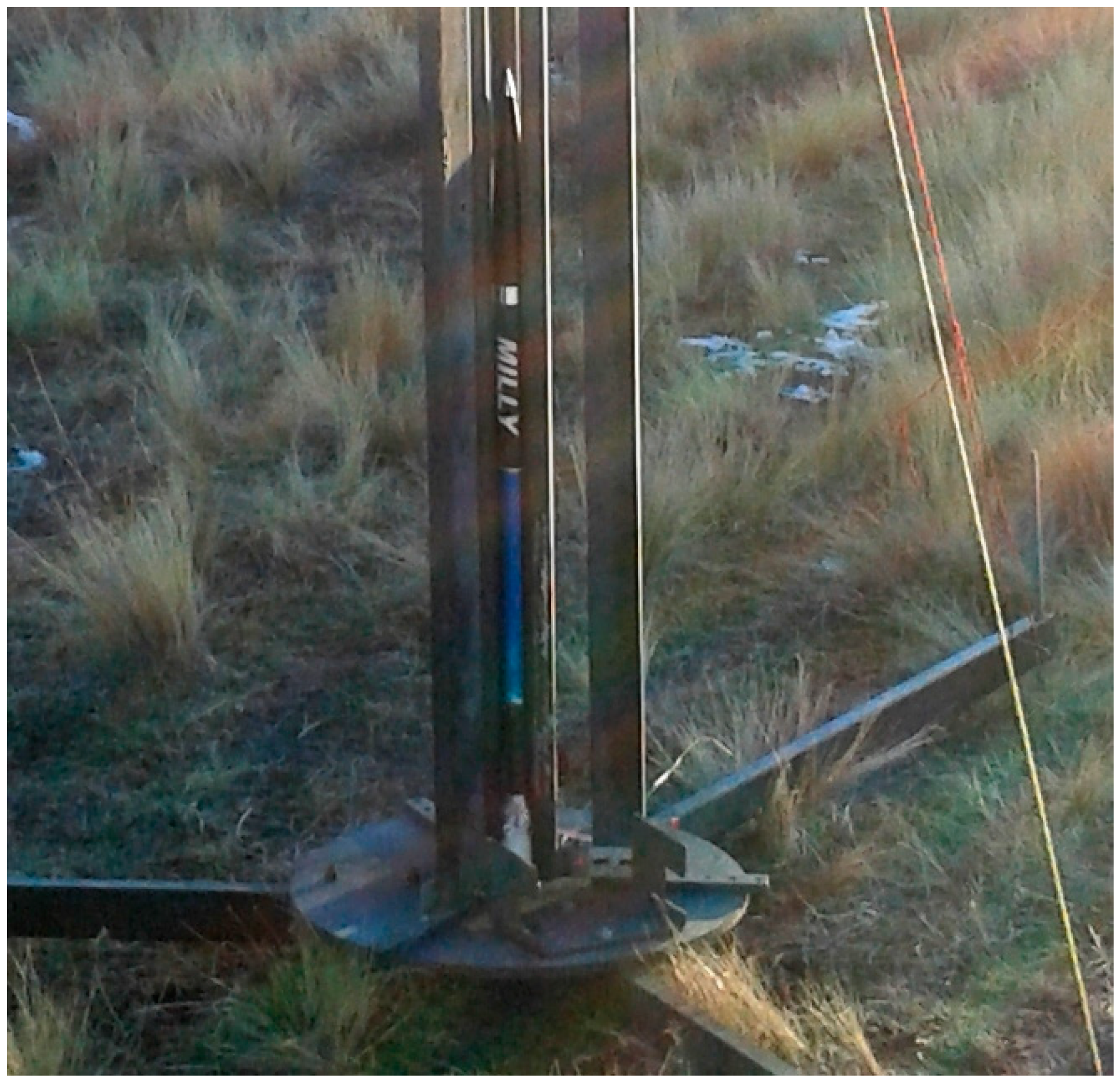
2.1.3. Rocket Recovery and Tracking Systems—Milly

The rocket Milly was recovered using a small nylon parachute to slow its descent; it measured 15 inches in diameter and was produced in-house. The parachute was deployed using a Telemetrum V2 altimeter, which is a commercially available device designed specifically for the task. The Telemetrum measures the altitude of the rocket using a combination of accelerometers, a barometer and GPS and will fire ejection charges at a variety of user selectable points. For Milly the parachute was set to eject at apogee to minimize the strain on the parachute and increase the chances of the rocket being retrieved in one piece.
The primary tracking method was GPS. However a 4.31 MHz beacon was also placed in the rocket and tracked with a standard Yagi antenna. This method provided a back-up to the GPS.

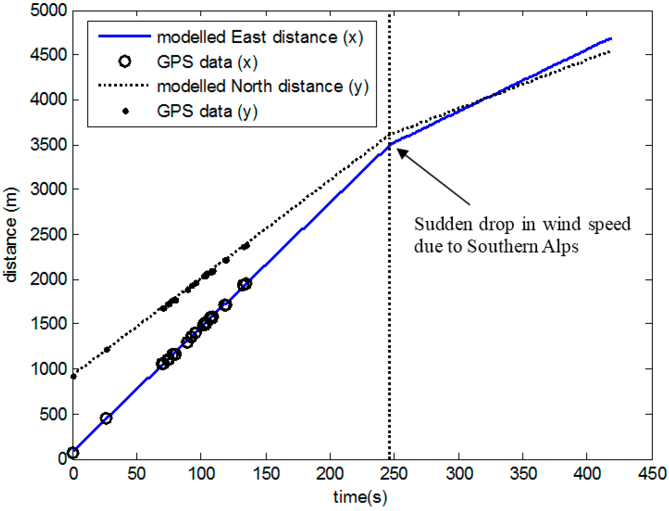
2.2. Parachute Descent 3DOF Modelling—Milly

Since only descent data was recovered during the flight due to a loss of GPS signal with the high accelerations, the initial time for modelling was taken from apogee and set to t = 0. To predict the maximum altitude and approximate landing site of the world record rocket, a 3DOF model was developed. This model uses the standard dynamic pressure formulation for drag (e.g., [35]) and is defined by:
( v ˙ x v ˙ y v ˙ z ) = 1 M ( F d V ˰ c m , R M g ( 0 0 1 ) )
( x ˙ y ˙ z ˙ ) = ( v x v y v z )
V ˰ c m , R = 1 ( v x , R 2 + v y , R 2 + v z , R 2 ) ( v x , R v y , R v z , R ) , F d = 1 2 C d , p ρ ( v x , R 2 + v y , R 2 + v z , R 2 ) A p
g = G M E ( r E + z ) 2 , v x , R = v x w x , v y , R = v y w y , v z , R = v z w z
initial   conditions x ( 0 ) = x 0 , y ( 0 ) = y 0 , z ( 0 ) = z 0 , v x ( 0 ) = v x 0 , v y ( 0 ) = v y 0 , v z ( 0 ) = v z 0
where the air density ρ is a function of altitude which is based on the 1967 US standard atmosphere.

2.3. University of Canterbury Rocketry Design and Control Course—Smokey

This course named ENGR402—Rocket Systems and Design, was developed to give students hands-on experience in all aspects of a rocket launch and the opportunities of entering the New Zealand space industry after further training in postgraduate work with UC rocketry. The course included supervision and a significant amount of technical input from former UC Rocketry postgraduates employed at Rocket Lab. This supervision included training of postgraduate students who were teaching assistants in the course, regular contact with the course students, guest lectures, the construction of an uncontrolled rocket for parachute testing and assistance in the rocket launch procedures, with particular emphasis on safety.
A further part of the course included an assignment on using Astos software [3] to investigate the impact of errors in the first stage trajectory on orbital insertion accuracy of the Minotaur rocket. This assignment gave the students a basic first course on trajectory optimization with Astos.
The final part of the course was the rocket airframe and avionics assembly, wind tunnel testing of control systems, and launch of the course rocket “Smokey” at Kaitorete Spit, which involved all eight students. The main goal of the launch was to test the effectiveness of the canards and actuation system, but most importantly provide data on an actuated attitude response. This data will help to create 6DOF models in the future which will enable more advanced controllers to be developed. More details of the flight are given in the results section. The stability, geometry, and motor characteristics are given in Table 1. The course rocket assembly including motor and fins is shown in Figure 3.
Table 1. Smokey specifications.
CategoryParameterValue (Liftoff, Burnout)
StabilityCentre of Pressure0.80 m
Centre of Mass0.71 m, 0.66 m
Stability1.2 Calibres, 1.8 Calibres
Mass3.0 kg, 2.75 kg
GeometryRocket Diameter0.08 m
Reference Area0.005 m2
Rocket Length1.52 m
Canard Location0.3 m
Tail Fin Location1.4 m
Canard Radial Distance0.06 m
Nozzle Location1.5 m
MotorTypeAerotech I211W
Total impulse440 Ns
Avg. thrust217 N
Max. thrust386 N
Burn time2.02 s
Launch mass476 g
Empty mass226 g
Figure 3. Smokey rocket assembly.
Aerospace 02 00091 g003

2.3.1. Safety Protocols—Smokey

The students of the course attended a rocket launch from UC rocketry postgraduate students in the first week of term. The main aim was to show the safety protocols developed by UC Rocketry and the students had to summarize their observations in a 5% course assessment. The safety protocol has been developed over several years and is summarized as follows:
  • NOTAM is lodged with Airways New Zealand
  • Safety and Consent forms are filled for University of Canterbury administration
  • High-visibility vests are worn by all on site
  • Safety glasses are worn when working with or near explosive charges
  • A fire blanket, fire extinguisher and water container are available on site
  • First Aid certification must be held by someone on site
  • The parachute charge is inside the nose cone; the nose must always be pointed away from other people when handling the rocket
  • Continuity of the ignition leads is checked before connecting the explosive charge
  • Check for aircraft immediately before launching
  • Remain in the bunker during launch until it is deemed safe to leave
  • Bring the fire extinguisher to the landing site when recovering the rocket
  • If the rocket misfires, remain in the bunker for 60 s before approaching the launch guide

2.3.2. Electronic Housing 3D Printing Assignment—Smokey

In the first half of the course the students were required to design an enclosure for the electronics of the course rocket, Smokey. The requirements included ensuring the correct positioning of all sensors, allowing all relevant parts of the electronics to be accessed, securely supporting all the required componentry and its ability to be produced in the 3D printers provided. The highest marks were awarded to students who presented a complete list of specification for their parts and then designed a suitable enclosure that met both their specifications and ones that they were told they had overlooked. The best design was selected to be 3D printed for the rocket.

2.3.3. Machining of Rocket Parts—Smokey

The students machined the majority of the rocket parts and the remaining parts were outsourced to a local machining company. The list of rocket parts is shown in Table 2 and Figure 4.
Table 2. Labelled Smokey rocket parts from Figure 4.
LabelPartMaterial
AMotor Centering RingAluminum
BActuator Housing CoverAluminum
CAirframe TubePVC
DCanard Shaft BushingsBronze
EEncoder SpacersBronze
FActuator Base DiskAluminum
GCanard ShaftsStainless Steel
HChute Strop PinStainless Steel
IChute Fair LeadAluminum
JDrogue BarrelAluminum
KEjection CanisterAluminum
LEjection Piston BaseAluminum
MNose Cone TipAluminum
NNose Cone Tie TubeAluminum
Figure 4. Student parts for Smokey machined in the rocketry course.
Aerospace 02 00091 g004

2.3.4. Avionics—Smokey

The foundation for the avionics was developed from 2011 to 2013 for the Lisa I–III and Tasha I and II vehicles [1]. The avionics were redesigned to simplify the manufacturing of multiple rockets and to increase the process speed of the on board computer. The major areas of this redesign are summarized as follows:

Microprocessor Change to ARM Cortex-M4 STM32F4

The STM32F4 provides powerful processing performance and a large number of on-chip peripherals. Featuring an on-board FPU (floating point unit) along with a 168 MHz clock allows the microprocessor to perform accurate control calculations quickly. This advantage enabled the students to easily access control data while experimenting with the hardware. On-chip peripherals simplified board design allowing logging, communications, control interfaces and debugging all on the same chip.

Software Improvements

The STM32F4 processor allows FreeRTOS to be implemented in software. Routines previously optimized for previous launch vehicles were rewritten making them easier to maintain. Students were involved in the design and implementation of communications, interface, logging and wind-tunnel GUI software (FreeRTOS, Real Time Engineers Ltd, London, UK) in this project.

MPU6000 IMU Sensor

The MPU6000 IMU provided gyro and accelerometer data at 330 Hz. The 16-bit resolution was suitable for rocket control and the small QFN package minimized board space requirements.

Combination of Functionality on One PCB

A major improvement from Lisa I–III and Tasha I and II [1] was the combining of avionics to one PCB. Computational, sensor, logging and power circuitry were combined on one board. This allowed easier building and mounting solutions. Improvements in assembly simplified the process of accessing and debugging the hardware.

2.3.5. Actuation Mechanism—Smokey

The course rocket Smokey utilizes canards for control. The canards and fins are 3D printed in ABS plastic. Each canard is actuated by a Futaba BLS251 brushless servo via pushrods. This arrangement gives ±20° of movement per canard which is beyond the designed 15° stalling angle of the canard aerofoil. Each canard shaft has a US Digital E4P360157NSHMB encoder. These encoders provide real-time feedback of the actual canard position with ±0.25° resolution during flight. Figure 5 shows how the servo controls the position of the canard. Servo actuations move a pushrod, which is attached to the shaft horn to turn the canard. An encoder is placed behind the shaft horn and provides a means of compensation for the non-linear nature of the actuation mechanism. Figure 6 shows the finished design. The goal of the canards for this Smokey launch was to minimize the roll rate, provide constant yaw control and to record data on the response for small open-loop actuations for later modelling to develop more advanced control algorithms.
Figure 5. Close up of actuation mechanism for Smokey.
Aerospace 02 00091 g005
Figure 6. Final actuation assembly for Smokey.
Aerospace 02 00091 g006

2.3.6. Parachute Recovery—Smokey

The parachute recovery system of Smokey was identical to the Lisa I–III and Tasha I–II rockets [1], but the telemetrum was used for automatic deployment, since it had worked so successfully in the Milly rocket launch. There was also a manual deployment option connected in parallel with the telemetrum. The manual deployment circuitry is a simple 2.4 GHz wireless system, which is first armed, then fired. The uncontrolled rocket was built by one of the authors (Malcolm Snowdon) and was used to provide two prior tests of the parachute deployment system. Both launches were successful and gave confidence for the final controlled launch of Smokey. Figure 7 shows an example of an earlier rocket with a similar system coming down under parachute.
Figure 7. An earlier rocket (Lisa III) coming down under parachute.
Aerospace 02 00091 g007

2.3.7. Wind Tunnel Testing—Smokey

To provide an initial validation of avionics, airframe and control algorithms for Smokey, a vertical wind tunnel has been built at the University of Canterbury. Specifically, by data logging the control inputs and output rocket attitude response in pitch, roll and yaw, the software can be debugged to ensure the actuations are in the right direction with the right magnitude, the mathematics are coded correctly, and the input rate gyro values are in the correct reference frame. It also proves that the hardware is running correctly and that it would remain functional for a rocket flight, and provides information on the normal force and canard coefficients to help create virtual rocket simulations. These pre-launch tests have been a crucial element in the success of UC Rocketry [1]. The specific goal in the wind tunnel tests with Smokey was to develop a derivative (D) controller on roll and a PD controller on yaw with gains chosen to minimize the roll rate and to hold the yaw as constant as possible in the wind tunnel. Figure 8 shows the wind tunnel with the key features labelled including a large suck-down fan at the base. There is also a flow straightener at the top of the converging section, which significantly reduces turbulence and creates close to laminar flow. The top speed of the wind tunnel is approximately 120 km/h. The test rocket is either held from a string to test roll control with minimal friction, or is placed on a gimbal frame to test full attitude control. Rockets up to 2 m long can be tested with an angle of attack up to ±10°, which covers most flight conditions in the first part of the flight. Figure 9 shows this gimbal frame setup.
Figure 8. Wind tunnel used for validating rocketry systems before flight.
Aerospace 02 00091 g008
Figure 9. Gimbal frame set up in wind tunnel.
Aerospace 02 00091 g009

3. Results and Discussion

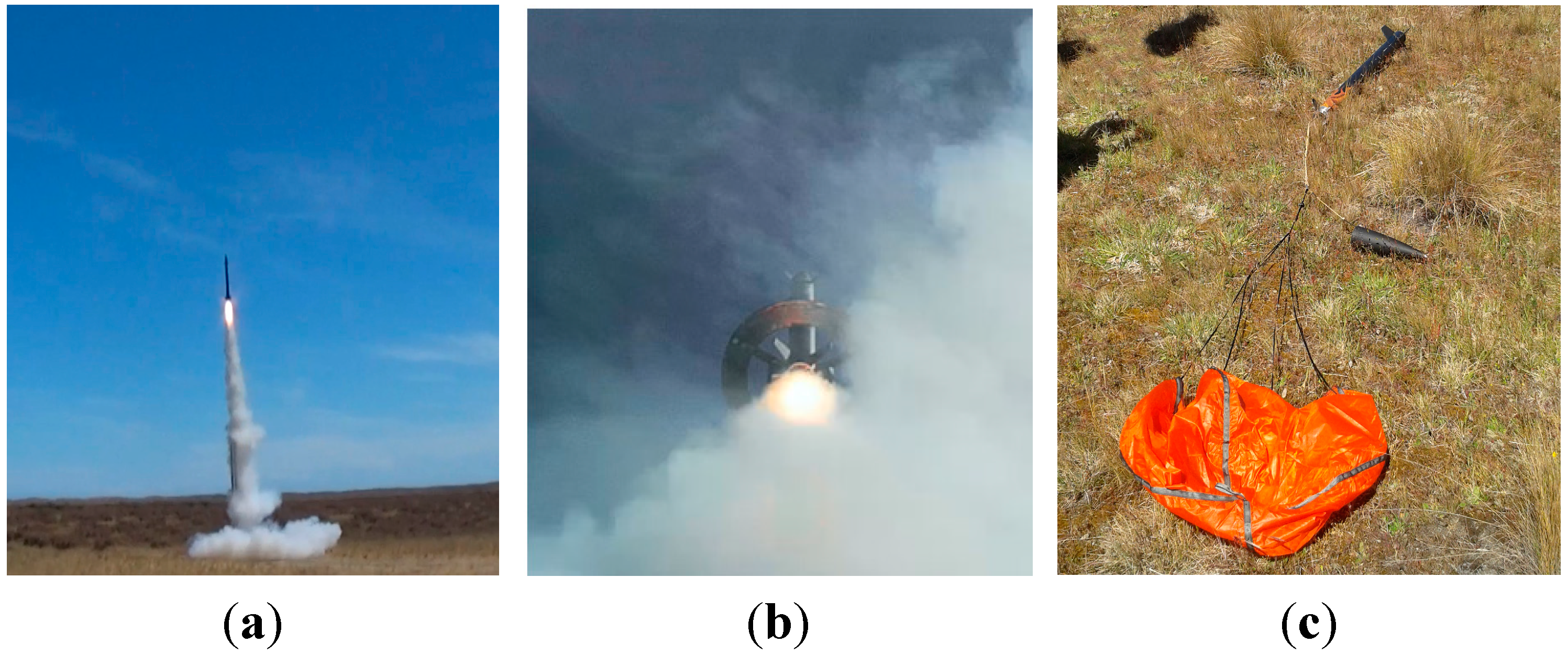
3.1. Rocket Launch Setup—Milly

The launch site for the rocket Milly was on private land approximately half way between Lake Tekapo and Lake Pukaki in the South Island of New Zealand. This site has 8 km of uncontrolled airspace above sea level. Figure 10 shows an aerial shot of the launch area, Figure 11 shows the launch guide with Mount Cook in the background and Figure 12 shows Milly inside the launch guide. Note that the original 4 m launch guide was extended to 5 m to provide a higher launch velocity to minimize thrust offset and weather cocking and thus provide a greater chance of beating the world record. This extra metre increased the speed off the launch guide from approximately 300 km/h to 350 km/h. Prior to launch of the main rocket, an exact 3D printed version was tested with a smaller motor. This rocket only reached an altitude of a few hundred meters, but was critical to provide the confidence to launch the main world record rocket.
Figure 10. Aerial shot of the launch area for Milly.
Aerospace 02 00091 g010
Figure 11. Launch guide and terrain with Mount Cook in background.
Aerospace 02 00091 g011
Figure 12. Milly inside launch guide.
Aerospace 02 00091 g012

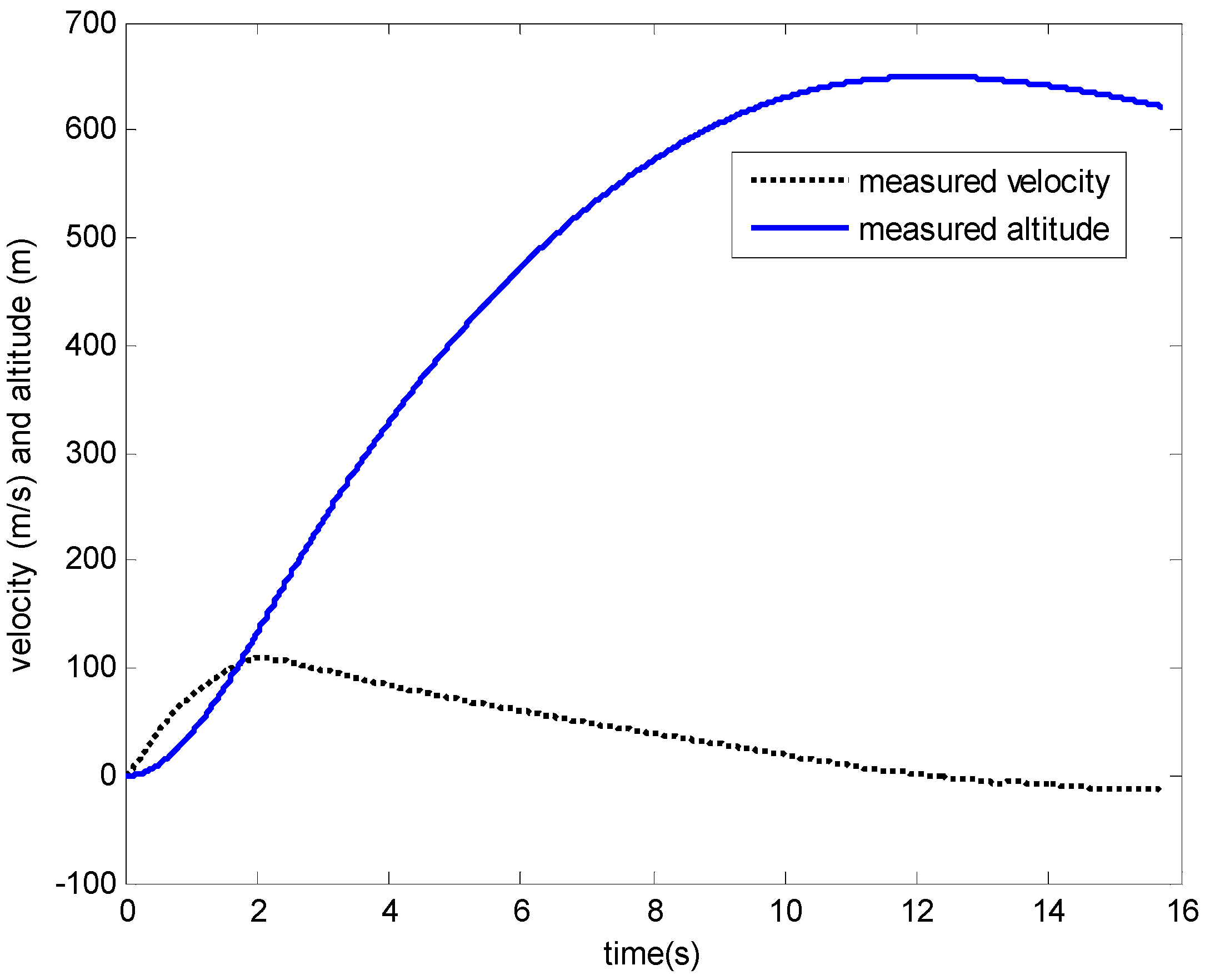
3.2. World Record Results—Milly

The small supersonic rocket Milly was launched on 26 July 2014. The rocket reached speeds in excess of 2000 kilometers per hour and broke the sound barrier just 70 m above the ground. The highest GPS data point obtained was 4889 m, which eclipsed both the previous New Zealand and world records of 1117 m and 4324 m respectively. Figure 13 shows the rocket leaving the launch guide and Figure 14 shows the rocket during thrust burn from a UAV. A reasonable amount of GPS data was received wirelessly during descent soon after apogee. This data proved that the parachute deployed successfully and confirmed that the world altitude record had been achieved.
Figure 13. Milly rocket leaving the launch guide.
Aerospace 02 00091 g013
Figure 14. Still photo of Milly from unmanned aerial vehicle (UAV) video footage.
Aerospace 02 00091 g014
To further analyze the response, the 3DOF model of the rocket descent under parachute, given by Equations (1)–(5) was used to predict both the maximum altitude and the approximate landing site. Note that the initial conditions of Equation (5) are unknown since the GPS data was only received after apogee. The other unknown parameters are the wind speeds wx, wy, wz and the drag coefficient Cd,p of the parachute. All the rest of the parameters are known and their numerical values are defined:
G = 6 . 6742 × 10 11 m 3 k g 1 s 2 , M E = 5 . 9742 × 10 24 k g , R E = 6378100 m
M = 1 . 05 k g , A p = π ( 0 . 3 2 ) 2 m 2
where 0.3 refers to the diameter of the parachute. The GPS data was recovered about 26.3 s after apogee and the signal was lost after about 135 s. During this period the altitude measurement was between 3.39 and 4.89 km.
To model the wind speeds the sheltering effect of the Southern Alps was taken into account by assuming the wind speed drops by half below the level of the Alps. This value is essentially arbitrary and not critical to the analysis, but would provide a better prediction of the landing spot compared to a constant wind speed across all altitudes. It was also backed up by local pilots in the area that have observed much lower wind speeds below the average level of the Alps which was assumed to be 2 km above ground level or equivalently 3 km above sea level. The vertical wind speed wz was assumed to be 0. Piecewise constant models of wind speed are defined:
w x ( z ) = w x 0 , z 2 km = 1 2 w x 0 , z 2 km
w y ( z ) = w y 0 , z 2 km = 1 2 w y 0 , z 2 km
An initial approximation to wx0, wy0, vx0, vy0, x0, y0can be computed from fitting a least squares line to the x and y displacement data, where x0, y0 are the 0 intercepts and vx0 = wx0, vy0 = wy0 are the gradients. The values are then updated in a grid search including Cd,p to minimize the least squares between the numerical output of the model from Equations (1)–(5) and the measured GPS data. The final numerical values are defined:
w x 0 = 13 . 85 , w y 0 = 14 . 0 , v x 0 = 14 . 0 v y 0 = 11 . 18 , X 0 = 73 . 4 , Y 0 = 922 . 6
and the results are plotted in Figure 15 and Figure 16.
Figure 15. Modelled versus measured altitude.
Aerospace 02 00091 g015
Figure 16. Modelled versus measured displacements in East (x) and North (y) directions.
Aerospace 02 00091 g016
The official world altitude record was 4.89 km, however, the modelled data in Figure 15 shows that the rocket reached an altitude of approximately 5.25 km, which is nearly 1 km more than the previous world record. Figure 16 shows that the rocket drifted under parachute about 4–5 km away from the initial launch site at a wind speed of around 14 m/s. The precise landing site was unknown, as the rocket was not recovered, since it was very small and the landing velocity was quite high around 10 m/s so it was likely buried in snow. Therefore, the data after the level of the Southern Alps gives only a rough idea of the drift under parachute. However, a quite sharp decrease in wind speed shown by the “kink” in Figure 16 is realistic due to the sheltering effect of the Alps. The estimated apogee was 920 m north of the launch site which corresponds to a total angle of 10° from vertical which is an excellent result and shows that the rocket remained close to vertical with minimal thrust offset and weather cocking.

3.3. Wind Tunnel PD Control Testing Results—Smokey

A number of wind tunnel tests were done by the students prior to the final rocket launch. The aim was to determine the PD controller gains in both the roll and the yaw axes. The pitch axis was not actuated in either wind tunnel tests or flight, to simplify the modelling and analysis of the post launch data and to avoid coupling of the axes, which makes hardware or software errors harder to debug. In addition, this was the first controlled flight test of the new hardware built and programmed by the students, so actuations were kept to a minimum for safety and to ensure successful recovery. Future flights will have all axes actuated in a similar way to Tasha II [1]. The controllers were defined by:
finAngleRoll = K d , r o l l ( 0 p )
finAngleYaw = K p , y a w ( R y a w yaw ) + K d , y a w ( 0 r )
After several experiments the optimal set of gains that minimized the variations in roll and yaw angle were defined by:
K d , r o l l = 0 . 2 , K p , y a w = 8 , K d , y a w = 10 , R y a w = 0
Figure 17a,b plot the roll and yaw angle response during a period of data with the gains from Equation (13). The results show good control except during the period of 30 and 35 s, where there was a significant disturbance in the wind tunnel. This disturbance was caused by outdoor wind conditions. In this period notice the significant roll, yaw coupling. After 35 s, the mean yaw angle was 1.1° with a standard deviation of 0.8° and the mean roll angle was −3.4° with a standard deviation of 2.2°.
Figure 17. PD controller results for Smokey (a) yaw angle response (b) roll angle response
Aerospace 02 00091 g017

3.4. Kaitorete Spit Launch Site and Set up—Smokey

The launch of Smokey was conducted on Kaitorete spit from an old military bunker. The terrain is flat with low-growing vegetation making it ideal for rocket recovery. The bunker shown in Figure 18 provides a safe launch control facility with a reinforced concrete roof.
Figure 18. World War II storage bunker on Kaitorete Spit.
Aerospace 02 00091 g018
The roll and yaw actuation protocol followed during the launch was:
  • A derivative controller on roll angle given by Equation (11), implemented throughout flight
  • A PD controller on yaw angle given by Equations (12) and (13) but with Ryaw replaced by the measured yaw angle, four seconds after launch detect. Four seconds was chosen since the thrust burn was 2.2 s, and it gives sufficient time for effects of weather cocking and thrust off set to disappear and provides a more conservative test of the controller in conditions of a slower varying velocity.
  • Three open-loop step responses of the yaw fin angle defined by:
    finAngleYaw ( t ) = 3 ° , 5 < t < 7   after   launch   detect = 3 ° , 7 < t < 9 after   launch   detect = 0 , otherwise
Note that an open-loop yaw actuation of Equation (14) was used as a conservative test of the attitude response since this flight was the first launch of the hardware.
In summary, the main aims of the controller were to test the roll rate control, see how well the yaw could be fixed at a predefined time during flight as well as test out open-loop control commands for future modelling of the vehicle. This launch helps to validate the new hardware and gives confidence for implementing the more advanced UC rocketry control algorithms that have been previously successfully applied on an earlier Tasha II vehicle [1]. These earlier results provided accurate pointing of the rocket within a mean error of 0.1° but require customized hardware that is hard to manufacture and not as flexible for further development. For example, future work is to include thrust vectoring and full guidance up to supersonic speeds [1].
To ensure safety and success in the launch of Smokey, UC rocketry’s launch protocols were followed. In addition to the safety protocols outlined in Section 2.2.1, the following protocols were exercised:
  • An equipment checklist was completed before going to the launch site, this included all gear needed to launch, safety equipment and documentation
  • Launch guide was set up
  • Rocketry electronics were powered on in idle state; this means there is no risk of the electronics performing in-flight tasks such as canard actuation, logging or parachute deployment
  • Rocket was placed inside the launch guide
  • Motor ignition cable was laid out and continuity tested
  • Base station was set up inside the bunker, and communications were checked
  • Motor ignition charge placed inside rocket motor, and armed at the launch guide
  • All present assembled inside the bunker for final countdown

3.5. Flight Results—Smokey

The course rocket Smokey was launched on 14 November 2014. It was a clear day and virtually no wind at ground level. The rocket flight path was very straight off the launch guide with very little thrust offset and no weather cocking. The parachute automatically deployed and successful recovery was achieved with a landing site about 400 m from the launch site. Figure 19a,b show the rocket leaving the launch guide and Figure 19c shows the rocket after landing.
Figure 19. Smokey leaving launch guide (a) video still; (b) Mobius on launch guide; (c) Successfully recovered rocket.
Aerospace 02 00091 g019
Figure 20 shows the vertical acceleration, velocity and displacement during the ascent phase of Smokey. The maximum speed reached was 110 m/s with an apogee of 650 m. Figure 21a,b show plots of the measured yaw angle and roll rate respectively during ascent. Note the very large oscillation in both yaw and roll after 12 s, which corresponds to parachute deployment. Figure 22a,b show a closer view of the control period. The yaw angle closed loop controller is turned on at 4.2 s with a reference of 18.6°, which corresponds to the yaw angle reached at this point in flight. There are a few small oscillations initially, but these are quickly damped out and during this period the yaw angle was held with a mean of 18.7° and standard deviation of 0.2°, which is excellent control. The roll rate is controlled reasonably well outside the period between 5 s and 7.5 s with a mean of 43.5°/s and standard deviation of 31.4°/s. However, during this period there is significant roll/yaw coupling. Specifically, as soon as the three-degree open-loop actuation input from Equation (14) is implemented the roll rate immediately starts to increase. This behavior shows that the roll controller of Equation (11) is too conservative and not able to compensate fully for this yaw actuation angle induced disturbance onto the rocket. The likely reason for the disturbance is that the yaw actuation to 3° causes a vortex which moves from the canards to the back fins.
Figure 20. Velocity and altitude from Smokey launch.
Aerospace 02 00091 g020
Figure 21. (a) roll rate controlled response (b) yaw angle controlled response.
Aerospace 02 00091 g021
Figure 22. Closer view of control results (a) roll rate response (b) yaw angle response.
Aerospace 02 00091 g022
Overall, the rocket avionics and actuation systems performed very well and combined with the successful launch and recovery of the rocket was an excellent outcome for the rocketry course.
Notice that there’s a delay of about 0.8 s before the yaw angle increases. It then decreases after about 1.7 s. The reason for this response is that an increase in canard yaw fin will induce an angle of attack which the rocket resists as it’s statically stable. Since this period is post thrust, and it’s a small time span, the velocity vector will not change significantly. Hence there’s a spring force preventing the change in yaw angle and 3° of fin does not provide enough torque, so the yaw angle eventually decreases. Similar behavior occurs when the yaw fin angle is moved to −3°. Note that the stability margin chosen, as shown in Table 1, was based on an earlier vehicle Tasha II that had very similar geometry. Tasha II provided accurate ±3° attitude changes with up to ±6° of fin angle [1]. Thus, the main reason for the small yaw changes in Figure 22b is that the fin angle was not large enough. However, this limitation was implemented to keep this test conservative while providing a sufficient attitude response that could be modelled for later launches. After 9 s, the airspeed slows considerably as it nears apogee so the yaw angle increases significantly.
Even though the roll control was sub-optimal during the open-loop step responses, there is a good amount of actuation response which can be used to develop better controllers in the future. For example, a PD control could be used in the roll and gain scheduling for the gains to account for the significant changes in airspeed and the full amount of fin angles of ±12° could be used for actuation.

4. Conclusions

A small supersonic, student built rocket named “Milly”, achieved the world altitude record for an I-class motor with a launch from Tekapo on 26 July 2014. The launch verified a number of new systems for UC rocketry including a new altimeter and tracking system, a graphite expander to improve the performance of the motor and a 5 m launch guide to minimize the effects of thrust offset and weather cocking due to a faster release velocity. This world record attempt provided excellent motivation for the postgraduate students involved and was an important foundation for future transonic and supersonic research at the University of Canterbury.
A rocketry course was run at the University of Canterbury, which was the first of its kind in New Zealand. It is the only rocketry course available world worldwide that includes attitude control with canards. The students design and build all electronic and mechanical components in the rocket including the airframe, 3D printing of canards, rocket engine assembly, instrumentation and sensors, control systems and parachute recovery. A summary was given of the student parts that were machined, the improved avionics, safety protocols and wind tunnel set up. The wind tunnel was used to initially develop the PD controllers in roll and yaw.
The final rocket, named “Smokey”, was launched by the rocketry course students on 14 November 2014. A successful recovery of the rocket was achieved; the data was logged and analyzed. The roll control gave an average of 43.5°/s except during a period of significant roll-yaw coupling due to the first open-loop actuation of the yaw fin. Previous launches on very similar vehicles without roll control have had roll rates around 500°/s due to canard offset errors and asymmetries in the airframe, hence 43.5°/s represents reasonable roll control. A single period of closed-loop yaw control was implemented over 1 s at 4.2 s into the flight. The controller held the yaw to within a mean value of 0.1° of the required reference angle and a standard deviation of 0.2°, which is an excellent result. After this period, several open-loop step responses were implemented in the yaw fin and provided a good actuation response for future analysis and modelling. The goal is to use this flight as the foundation for eventually implementing full attitude control and guidance using canards in the future. In addition, further research will be done on other actuation mechanisms like thrust vectoring and the effects of transonic and supersonic flow will be investigated including turbulence and shock waves.
The rocketry course was a complete success and the students have had a great opportunity to learn hands-on rocketry with assistance from former UC rocketry students that now work at Rocket Lab Ltd. Two of the students in the course have gone on to postgraduate work. The UC Rocketry group has developed rapidly in the past few years and is providing research and graduates to New Zealand’s space program, which has the aim of launching an orbital vehicle Electron in the near future.

Notation

Fd
drag force (N)
ρ
air density (kg m−3)
Cd,p
drag coefficient of parachute (dimensionless)
M
mass of the rocket with parachute and no fuel
g
acceleration due to gravity (m s−1)
vx, vy, vz
velocities (m s−1) in East, North and vertical directions
x, y, z
East and North displacements and altitude above ground level respectively (m)
vx,R, vy,R, vz,R
relative wind velocities in East, North and vertical directions (m s−1)
wx, wy, wz
wind speeds in East, North and vertical directions (m s−1)
Ap
area of parachute (m2)
G
gravitational constant (m3 kg−1 s−2)
ME
mass of earth (kg)
rE
radius of earth (m)
x0, y0, z0, vx0, vy0, vz0
initial conditions at apogee
finAngleRoll
fin angle actuating roll (rad)
finAngleYaw
fin angle actuating yaw (rad)
Kd,roll
derivative gain on roll (s)
Kp,yaw
proportional gain on yaw (no unit)
Kd,yaw
derivative gain on yaw (s)
Ryaw
reference yaw angle (°)
Abbreviations
PD
Proportional-derivative
LEO
Low earth orbit
NASA
The National Aeronautics and Space Administration
UC
University of Canterbury
NZ
New Zealand
US
United States
3D
Three dimensional
3DOF
Three degrees of freedom
ASTOS
Aerospace Trajectory Optimization Software
DARE
Delft Aerospace Rocket Engineering
Ph.D.
Doctorate of Philosophy
STERN
Student experimental rocketry
CNES
National Centre for Space Studies
ARES
Advanced Rockets for Experimental Studies
PERSEUS
Projet Etudiant de Recherche Spatiale Europeèn Universitaire Et Scientifique
CUSF
Cambridge University Space Flight
CALVEIN
California Launch Vehicle Education Initiative

Acknowledgments

We would like to acknowledge the Royal Society of New Zealand for the funding of the Rutherford Discovery Fellowship, Callaghan Innovation and the UC rocketry sponsors, ASTOS solutions in Germany, and the NZ companies Scott Machinery and Shamrock Industries. We would also like to thank Alana Miles, Marion and David Gould for allowing the use of their farm for the world record launch at Lake Tekapo and as a launch site for future UC rocketry launches, Nathn Trethowen for his UAV footage including the still of Figure 14 and Ian Trethowen for developing the beacon tracking system.

Author Contributions

George Buchanan, David Wright, Christopher Hann, Hoani Bryson, Adam Slee, Hans Philipp Sültrop, Malcolm Snowdon, Avinash Rao, XiaoQi Chen—developed the hardware, did the experiments, analyzed the data and wrote the paper.
Bastian Jochle-Rings, Zane Barker, Abigail McKinstry, Claude Meffan, George Xian, Ryan Mitchell—worked on the rocket Smokey including doing the experiments assisting in machining the rocket parts, helping with assembly of the electronics and gathering the data as part of the rocketry course.

Conflicts of Interest

The authors declare no conflict of interest.

References

  1. UC Rocketry Project. Available online: http://ucrocketry.org/ (accessed on 21 February 2015).
  2. Rocket Lab Ltd. Available online: http://rocketlab.co.nz/ (accessed on 21 February 2015).
  3. Astos Solutions. Available online: https://www.astos.de/ (accessed on 21 February 2015).
  4. Rocket Motors and Propellants. Available online: http://www.cranfield.ac.uk/courses/training/rocket-motors-and-propellants.html (accessed on 21 February 2015).
  5. Bachelor of Engineering Honours (Mechatronic) (Space). Available online: http://sydney.edu.au/courses/bachelor-of-engineering-honours-mechatronic-space (accessed on 21 February 2015).
  6. Rojas, J.I.; Prats, X.; Montiaur, A.; Garcia-Berro, E. Model rocket workshop: A problem-based learning experience for engineering students. Int. J. Emerg. Technol. Learn. 2008, 3, 70–77. [Google Scholar] [CrossRef]
  7. Heath, M.T.; Dick, W.A. Virtual rocketry: Rocket science meets computer science. Computat. Sci. Eng. IEEE 1998, 5, 16–26. [Google Scholar] [CrossRef]
  8. UCT Engineering Students Launch Two Rockets. Available online: http://sastudy.co.za/article/uct-engineering-students-launch-two-rockets/ (accessed on 21 February 2015).
  9. Stratos II. Available online: http://dare.tudelft.nl/projects-and-teams/advanced-control/ (accessed on 21 February 2015).
  10. Farokhi, S. System design aspects of propulsion education in aerospace engineering curricula. Int. J. Turbo Jet Engines 1991, 8, 267–350. [Google Scholar] [CrossRef]
  11. Propulsion System Design Laboratory. Available online: https://explorecourses.stanford.edu/search?view=catalog&filter-coursestatus-Active=on&page=0&catalog=&academicYear=&q=AA284B&collapse (accessed on 21 February 2015).
  12. Stancato, F.; Racca, J.G.C. A 12 years Brazilian space education activity experience. Acta Astronaut. 2001, 48, 827–835. [Google Scholar] [CrossRef]
  13. MIT Rocket Team. Available online: http://rocketry.mit.edu/ (accessed on 21 February 2015).
  14. Jayaram, S.; Boyer, L.; George, J.; Ravindra, K.; Mitchell, K. Project-based introduction to aerospace engineering course: A model rocket. Acta Astronaut. 2010, 66, 1525–1533. [Google Scholar] [CrossRef]
  15. Cannon, R.L. Model rocketry as a teaching aid in science. Sch. Sci. Math 2010, 74, 471–475. [Google Scholar] [CrossRef]
  16. D’Alessio, M.; Lundquist, L. Computer supported Collaborative Rocketry: Teaching students to distinguish good and bad data like expert physicists. Phys. Teach. 2013, 51, 424–427. [Google Scholar] [CrossRef]
  17. NASA. Rockets Educator Guide; EG-2011–11–223-KSC; NASA: Washington, DC, USA, 2011. [Google Scholar]
  18. Tomita, N.; Watanabe, R.; Nebylov, A.V. Hands-on education system using water rocket. Acta Astronaut. 2007, 61, 1116–1120. [Google Scholar] [CrossRef]
  19. Stamminger, A. STERN—A rocket programme for German students. In Proceedings of the 21st ESA Symposium on European Rocket and Balloon Programmes and Related Research, Thun, Switzerland, 9–13 June 2013.
  20. Alger, S.; Ciezki, H.; Heislbetz, B.; Kitsche, W.; Schlechtriem, S. First Student-Hybrid-Thruster Test Campaign at German Aerospace Center (DLR). In Proceedings of the 52th Israel Annual Conference on Aerospace Science, Tel-Aviv and Haifa, Israel, 29 February–1 March 2012.
  21. Bellomo, N.; Barato, F.; Faenza, M.; Lazzarin, M.; Bettella, A.; Pavarin, D. Numerical and experimental investigation of unidirectional vortex injection in hybrid rocket engines. J. Propuls. Power 2013, 29, 1097–1113. [Google Scholar] [CrossRef]
  22. May, S.; Poppe, S.M.G.; Pöppelmann, M.; Sültrop, H.P.; Vörsmann, P. Development of a supersonic research rocket with hybrid rocket engine. In Proceedings of the European Conference for AeroSpace Sciences, Munich, Germany, 1–5 July 2013.
  23. Okninski, A.; Marciniak, B.; Bartkowiak, B.; Kaniewski, D.; Matyszewski, J.; Kindracki, J.; Wolanski, P. Development of the polish small sounding rocket program. Acta Astronaut. 2015, 108, 46–56. [Google Scholar] [CrossRef]
  24. Pernon, S.; Oswald, J.; Bec, R.; Hingre, H. Ares rockets demonstrators of french space agency project perseus. In Proceedings of the 20th ESA Symposium on European Rocket and Balloon Programmes and Related Research, Hyère, France, 22–26 May 2011.
  25. SERA1. Available online: http://www.sscspace.com/SERA1 (accessed on 21 February 2015).
  26. Cambridge University Space Flight. http://www.cusf.co.uk/ (accessed on 21 February 2015).
  27. California Launch Vehicle Education Initiative—Calvein. Available online: http://www.csulb.edu/colleges/coe/mae/views/projects/rocket/ (accessed on 21 February 2015).
  28. Culbertson, J.; Besnard, E.; Garvey, J. Application of wireless technology to CALVEIN launch vehicles. In Proceedings of the Fly by Wireless Workshop (FBW), Caneus, Orono, ME, USA; 2010. [Google Scholar]
  29. Xia, Y.; Lu, K.; Zhu, Z.; Mengyin, F. Adaptive back-stepping sliding mode attitude control of missile systems. Int. J. Robust Nonlinear Control 2013, 23, 1699–1717. [Google Scholar] [CrossRef]
  30. Ollerenshaw, D.; Costello, M. Model predictive control of a direct fire projectile equipped with canards. J. Dyn. Syst. Meas. Control 2008, 130, 1–11. [Google Scholar] [CrossRef]
  31. Hann, C.E.; Snowdon, M.; Rao, A.; Winn, O.; Wongvanich, N.; Chen, X. Minimal modeling approach to describe turbulent rocket roll dynamics in a vertical wind tunnel. Proc. Inst. Mech. Eng. G 2012, 226, 1042–1060. [Google Scholar] [CrossRef]
  32. Open source model rocket simulator. Available online: http://openrocket.sourceforge.net/download.html (accessed on 21 February 2015).
  33. Rogers Aeroscience RASAero Aerodynamic Analysis and Flight Simulation Software. Available online: http://www.rasaero.com/ (accessed on 21 February 2015).
  34. Rocket Drag and Stability. Available online: http://www.softpedia.com/get/science-CAD/aerolab.shtml (accessed on 21 February 2015).
  35. Box, S.; Bishop, C.M.; Hunt, H. Stochastic six-degree-of-freedom flight simulator for passively controlled high-power rockets. J. Aerosp. Eng. 2011, 24, 31–45. [Google Scholar] [CrossRef]

