Article

Optimization of Heat Exchangers for Intercooled Recuperated Aero Engines

by
Dimitrios Misirlis
1,*,
Zinon Vlahostergios
2,
Michael Flouros
3,
Christina Salpingidou
2,
Stefan Donnerhack
3,
Apostolos Goulas
2 and
Kyros Yakinthos
2
1
Department of Mechanical Engineering, Technological Educational Institute (TEI) of Central Macedonia, Serres 62124, Greece
2
Laboratory of Fluid Mechanics & Turbomachinery, Department of Mechanical Engineering, Aristotle University of Thessaloniki, Thessaloniki 54124, Greece
3
MTU Aero Engines AG, Munich 80995, Germany
*
Author to whom correspondence should be addressed.
Aerospace 2017, 4(1), 14; https://doi.org/10.3390/aerospace4010014
Submission received: 29 December 2016 / Revised: 21 February 2017 / Accepted: 26 February 2017 / Published: 13 March 2017

Abstract

:
In the framework of the European research project LEMCOTEC, a section was devoted to the further optimization of the recuperation system of the Intercooled Recuperated Aero engine (IRA engine) concept, of MTU Aero Engines AG. This concept is based on an advanced thermodynamic cycle combining both intercooling and recuperation. The present work is focused only on the recuperation process. This is carried out through a system of heat exchangers mounted inside the hot-gas exhaust nozzle, providing fuel economy and reduced pollutant emissions. The optimization of the recuperation system was performed using computational fluid dynamics (CFD) computations, experimental measurements and thermodynamic cycle analysis for a wide range of engine operating conditions. A customized numerical tool was developed based on an advanced porosity model approach. The heat exchangers were modeled as porous media of predefined heat transfer and pressure loss behaviour and could also incorporate major and critical heat exchanger design decisions in the CFD computations. The optimization resulted in two completely new innovative heat exchanger concepts, named as CORN (COnical Recuperative Nozzle) and STARTREC (STraight AnnulaR Thermal RECuperator), which provided significant benefits in terms of fuel consumption, pollutants emission and weight reduction compared to more conventional heat exchanger designs, thus proving that further optimization potential for this technology exists.

1. Introduction

The enhancement of aero engine performance and the reduction of fuel consumption and pollutant emissions have always been the focal point of intense engineering optimization efforts for both environmental and economic reasons. Currently, as air traffic is growing at an annual rate of 5% and global awareness regarding environmental issues arises, the necessity to improve the efficiency of aero engines becomes constantly more intense and evident. For these reasons, a large number of research projects have been initiated and funded by European Union in collaboration between the main European aero engine manufacturers, Universities and Research Institutes. These projects have been mainly aiming at the design of innovative aero engine concepts for achieving improved performance, reduced fuel consumption and reduced pollutant emissions, thus promoting the fulfillment of year 2020 ACARE (Advisory Council for Aviation Research and innovation in Europe) targets of 20% reduction in CO2 and 80% in NOx emissions, compared to the year 2000 levels, as mentioned also in [1,2].
In this direction, significant effort has been focused on the development of alternative technologies and their subsequent incorporation in innovative aero engine concepts for high-bypass turbofan engines. Such a technology concept is implemented in the Intercooled Recuperative Aero engine (IRA engine) configuration, which is presented in Figure 1a, which combines both intercooling and recuperation and is one of the key-objectives of the EU funded LEMCOTEC Collaborative Project [3], targeting reduction of air-traffic emissions by increasing the thermal efficiency of aero engines. The present work refers to activities carried out within this project, part of which has been presented also in [4].
The IRA engine concept has been also investigated within the framework of previously successfully completed major European research projects such as Component Validator for Environmentally-friendly Aero-Engine—CLEAN/FP5, NEW Aero engine Core concepts—NEWAC/FP6 and Low Emissions Core-Engine Technologies—LEMCOTEC/FP7. Additional information regarding this concept can be found in the works of [7,8,9].
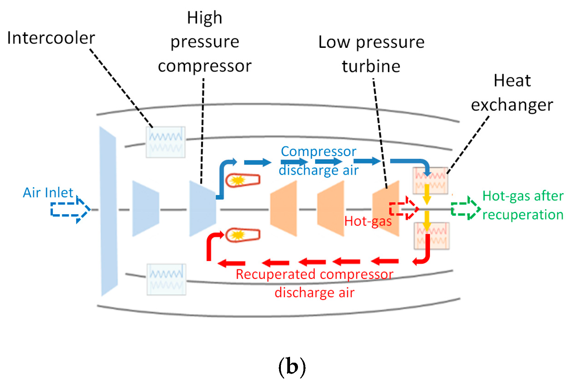
More specifically, this concept is based on a system of heat exchangers mounted inside the hot-gas exhaust nozzle and an intercooler placed between the compressor stages. The heat of the exhaust gases is recovered downstream of the exit of the low-pressure turbine and preheats the air which enters the combustion chamber with increased enthalpy, providing fuel economy and reduced pollutant emissions.
Regarding the recuperation system, the heat exchangers operate under harsh conditions combining both high temperatures and pressure. As a result, their thermo-mechanical performance and reliability is of primary importance, as presented in [10]. Furthermore, the imposed pressure losses affect the potential benefit of the aero engine thermodynamics cycle while the heat exchanger’s own weight reduces a part of the thermodynamic cycle efficiency improvement. For these reasons, the optimization of the recuperation system is of critical importance for the beneficial operation of the IRA engine concept, as pointed out in [11,12,13].
In addition, the use of intercooling, a technology which performs at its best for thermodynamic cycle conditions which facilitate recuperation, contributes to a reduction of high pressure compressor work leading to a further improvement of aero engine efficiency. Intercooling also makes recuperation more efficient as it increases the temperature difference between the hot exhaust gas and the high pressure compressor (HPC) exit air. Both intercooling and recuperation are utilising specially designed and integrated heat exchangers.

2. Optimization of Heat Exchanger Concepts

The present work is focused only on the recuperation process and more specifically on the optimization of both the geometry of the heat exchangers and their installation within the exhaust nozzle, in order to maximize the recuperation benefits, specifically targeted for an IRA engine. More details about the IRA engine concept can also be found in [2,9,14,15]. The implementation of recuperation in an IRA engine is performed through the mounting of a number of heat exchangers inside the hot-gas exhaust nozzle, downstream of the low-pressure turbine. The basic heat exchanger (HEX) of the IRA engine, which was invented and developed by MTU Aero Engines AG and was used for the initial HEX performance studies, is presented in Figure 1b. It consists of elliptically profiled tubes placed in a 4/3/4 staggered arrangement targeting high heat transfer rates and reduced pressure losses. Additional information of the HEX operation can be found in [10]. The HEX tubes’ geometry and arrangement can significantly affect the turbine expansion and thus degrade the produced turbine work due to the imposed pressure losses. The overall heat exchanger design plays a critical role since the above mentioned pressure losses are linked directly to the available heat exchange surface and its geometry, which in turn strongly affects the HEX effectiveness and the exhaust gas waste heat exploitation. As a result, to achieve the maximum recuperation benefits, a compromise between the HEX design parameters is required.
Towards this direction, the development of accurate and validated numerical tools is of particular importance since they can provide time- and cost-efficient design solutions which can lead to the a priori estimation of the HEX major operational characteristics (i.e., pressure losses and effectiveness). These operational characteristics can then be integrated in a thermodynamic cycle analysis of the aero engine in order to assess the recuperation effects on the aero engine efficiency and fuel consumption. Thus, these tools can significantly contribute to the development, assessment and optimization of various innovative heat exchanger concepts which otherwise could not be affordable in laboratory (due to time and cost limitations).

2.1. The Heat Exchanger–Recuperator Porosity Model Approach

The development and optimization of innovative heat exchanger concepts, focused on the Intercooled Recuperated Aero Engine, which are an evolution of the original MTU HEX design, are presented here. The investigation and the optimization reported in this work were performed with the use of 2D and 3D CFD computations, experimental measurements and thermodynamic cycle analysis, for a wide range of engine operating conditions. The optimization activities were mainly based on the use of an innovative customizable 3D numerical tool which could efficiently model the heat transfer and pressure loss performance of the heat exchangers of the IRA engine installation.
The numerical tool was based on an advanced porosity model approach in which the heat exchangers were modeled as porous media of predefined heat transfer and pressure loss behavior, which was determined by correlations specifically developed for the recuperator HEX. The use of a porous media methodology for modeling the heat exchangers provides significant advantages since it can facilitate the incorporation of the heat exchangers’ macroscopic heat transfer and pressure loss behavior in 3D CFD models of the overall aero engine installation (including the hot-gas exhaust nozzle and the precise mounting of the recuperator system inside the aero engine). In addition, the use of the numerical tool can be incorporated in CFD models, by being integrated to the fluid flow momentum and energy transport equations in the 3D CFD computations. This tool is able to provide consistent numerical solutions of the complicated flow inside the recuperator nozzle installation. Without the use of the presented numerical tool, 3D CFD computations of the precise recuperator detailed geometry could not be achieved due to the extremely high CPU and memory requirements since more than one billion computational points are estimated be necessary for the accurate representation of the overall nozzle and recuperator geometry.
This approach has been successfully applied in the past as presented in [14,15] and it was shown that the use of porous media methods in combination with CFD computations can lead to accurate and computationally affordable CFD models which can provide the basis for optimization of the overall geometrical configuration. In the present approach, the most important part is the accurate incorporation, through appropriate correlations, of the overall heat transfer and pressure losses in the macroscopic performance of the heat exchangers. Here, these correlations have been derived through detailed CFD computations and the use of experimental measurements, as presented in detail in [16,17], and were numerically incorporated in the CFD models of the overall aero engine installations by adding appropriate source terms in the momentum and energy transport equations. These correlations included the effect of both flow currents, i.e., inner-cold air and outer-hot-gas flows, on pressure losses, together with the achieved heat transfer between them.

2.2. Hot Side Pressure Loss Model

The hot-gas pressure losses, per unit length of the heat exchanger, were modeled using the following equation (in an isotropic formulation where the same coefficients are used in all three directions in space):
Δ P / L = [ ( a 0 + a 1 ν ) μ U + ( b 0 + b 1 ν + b 2 ν 2 ) ρ U 2 ] / L
Equation (1) is a modified formulation of the Darcy–Forchheimer pressure drop law with the pressure drop coefficients being functions of the kinematic viscosity and thus, functions of both pressure and temperature. The values of coefficients a 0 , a 1 and b 0 , b 1 , b 2 correspond to the viscous and inertial pressure loss coefficients which were derived through a trend line curve fitting process. The coefficients were derived through detailed 2D CFD computations on the heat exchanger core outer flow (the hot gas flow), which were validated against both experimental isothermal and non-isothermal measurements. These coefficients were calibrated for outer flow conditions covering the whole extent of the operational range of the heat exchanger (i.e., for Take-Off, Average Cruise and Max Climb conditions).

2.3. Cold Side Pressure Loss Model

Regarding the inner flow, cold-air, pressure losses of the heat exchanger, they were modeled by using a CFD-derived pressure loss per tube length coefficient, f , given by the following equation:
f = C 1 ( ln R e ) C 2
This was calibrated in relation to the inner flow mean Reynolds number based on detailed 3D CFD computations, which were carried out taking into account the precise inner geometry of the tubes.

2.4. Heat Transfer Model

The inclusion of heat transfer in the modeling of the heat exchanger required the calculation of the inner and outer heat transfer coefficients. An approach based on a Nusselt–Prandtl–Reynolds number correlation was used, given by Equation (3):
N u ¯ = C P r m R e n
where the coefficients C , m and n were calibrated through detailed CFD computations and experiments separately for each of the inner and outer flow streams, while all properties were calculated at the mean flow temperatures. It must be mentioned that similar analysis was performed for various tube core geometries, corresponding to different number of tubes and staggered arrangement (e.g., heat exchanger cores of 3/2/3, 4/3/4, 5/4/5, 6/5/6 tubes staggered arrangement and for different tubes spacing have been tested, in which the tube spacing has been almost doubled in relation to the initial MTU design) and various pressure loss and heat transfer correlations were derived for each tube’s core configuration, which were exploited for the optimization of the recuperator geometrical characteristics. These analyses also provided data for the most efficient selection of the heat exchangers’ core for both CORN (COnical Recuperative Nozzle) and STARTREC (STraight AnnulaR Thermal RECuperator) concepts, in which different numbers of tubes and arrangement were used in the recuperators’ cores.
As the next step of the analysis, the pressure losses and heat transfer correlations were included in the momentum and energy Reynolds Averaged Navier–Stokes equations of the Fluent CFD software [18] as additional source terms, as presented in Figure 2, through specially programmed User Defined Functions (UDF).
The set of equations presented in Figure 2 is solved for the outer flow. The thermal energy exchange of the two heat exchanger flow streams is achieved through the energy source term given by Equation (4),
U o v e r a l l ( T T i n n e r ) S e x c h a n g e
where T i n n e r refers to the temperature of the inner flow, S e x c h a n g e is the heat exchange surface per unit volume of the heat exchanger (m2/m3), calculated as the ratio of the total outer surface of the heat exchanger tubes to the occupied volume of the heat exchanger, while U o v e r a l l corresponds to the overall heat transfer coefficient and is calculated by Equation (5),
1 U o v e r a l l = 1 h o u t e r + 1 h i n n e r
where h i n n e r and h o u t e r are the inner and outer heat transfer coefficients calculated separately for each flow current using Equation (3).
For the appropriate modeling of the inner flow (cold air flow), two additional 1D transport equations, Equations (6) and (7), were coupled with the equations presented in Figure 2. These transport equations model the transport of the total specific enthalpy and the total pressure of the inner flow and were also implemented in the CFD computations through the use of UDF in the Fluent CFD software.
For the inner flow, the calculation of R e and   P r numbers at every computational cell and the temperature T i n n e r must be known. The inner flow temperature, T i n n e r is provided by the 1D transport Equation (6), via the calculation of the total specific enthalpy, given in Equation (8).
l [ ρ u i n n e r h t o t a l ] = U o v e r a l l ( T i n n e r T ) S e x c h a n g e
l P t o t _ i n n e r = f ρ u 2 i n n e r 2 D
h t o t a l = h s t a t i c + 1 2 u 2 i n n e r
In Equation (6), the right hand side is calculated from the computations of the outer flow. This is a parameter reflecting the geometrical structure of the heat exchanger core and is directly linked to the selection of the tubes’ staggered arrangement and number.
The inner “cold” air velocity, u i n n e r , is calculated from the prescribed “inner” mass flow inside the tubes, taking into consideration the density variations due to temperature and pressure along the tubes. The inner flow total pressure losses along the tube were obtained by the numerical integration of Equation (7).
The main advantage of the presented porosity model in relation to previous porosity models used for similar setups, as presented in [19,20], is that both flow currents are included in the model equations and thus, the derived model can simultaneously provide both the inner and outer flow pressure losses.
In addition, the specific model can calculate the 3D distribution of the achieved heat exchange between the outer hot-gas and inner-cold air flow, something which cannot be computed through a literature-based effectiveness-NTU method. Furthermore, the direct effect of the heat exchanger core geometry, such as the shape and size of the tubes, on the achieved heat transfer can be straightforwardly computed; the actual heat exchanger effectiveness can be calculated and then be taken into consideration in the aero engine cycle thermodynamic analysis. Some additional details about the customizable numerical tool can be found in [21].
Additionally, this innovative customizable 3D numerical tool can also incorporate major and critical heat exchanger design parameters in the CFD computations, by supporting the numerical integration of heat exchanger geometrical characteristics (e.g., tubes collector numbers, streams flow splitting and mixing, tubes core arrangement).
It should be mentioned again here that the use of the currently presented, porosity-model-based approach for the heat exchanger geometry, is almost obligatory since the inclusion of the precise heat exchanger geometry in a CFD model would result in an extremely high number of computational points which could not be computationally affordable in terms of CPU and memory (RAM) resources (more than 1 billion computational points would be required for the accurate modeling of the overall exhaust nozzle installation with the heat exchangers of the recuperators installation). On the other hand, the use of a porosity model approach where the recuperator heat exchangers are modeled as regions of predefined pressure loss and heat transfer characteristics, allows for the use of an affordable computational grid to obtain an accurate modeling of the overall exhaust nozzle configuration which can be used for further engineering analysis. Moreover, if someone attempted to model a small part of the heat exchanger core through the detailed CFD modeling of both inner and outer flows, together with the modeling of the tubes walls, and attempted to model the same part of the heat exchanger core with the use of the currently presented approach, the required time for the convergence of the detailed CFD model would be larger by a factor of 80 while both models would provide results of similar accuracy, as presented in detail in [21].

3. Results of the Recuperation Concepts

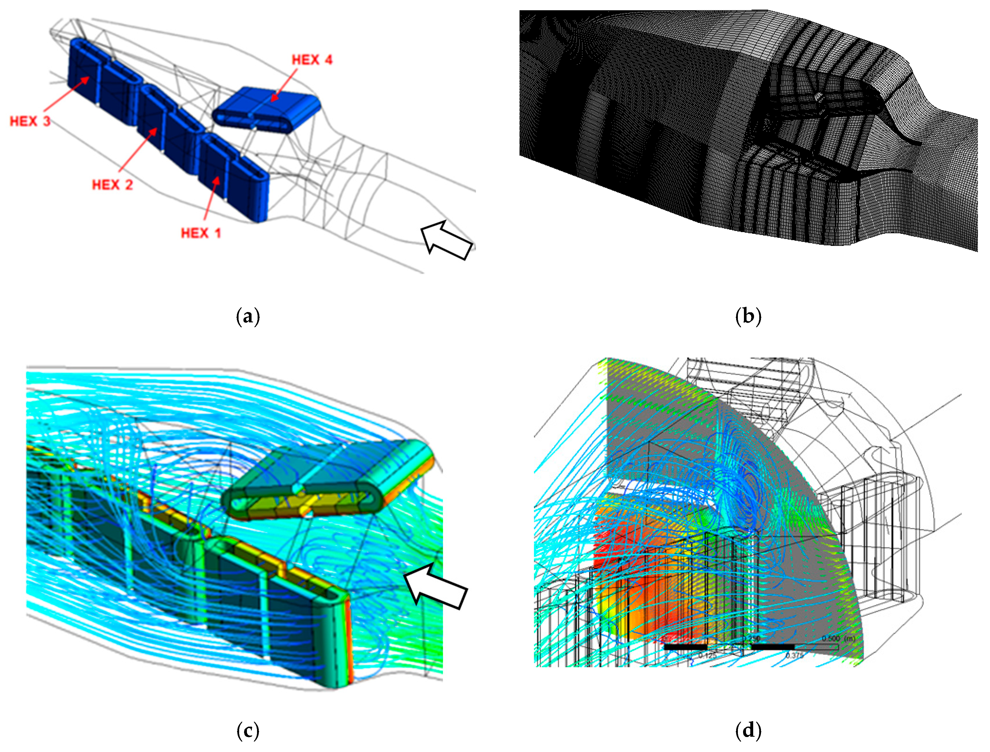
As a first stage of the present investigation, the aforementioned numerical model was applied to the NEWAC nozzle configuration, shown in Figure 3a, related to the NEW Aero engine Core concepts/NEWAC research project.
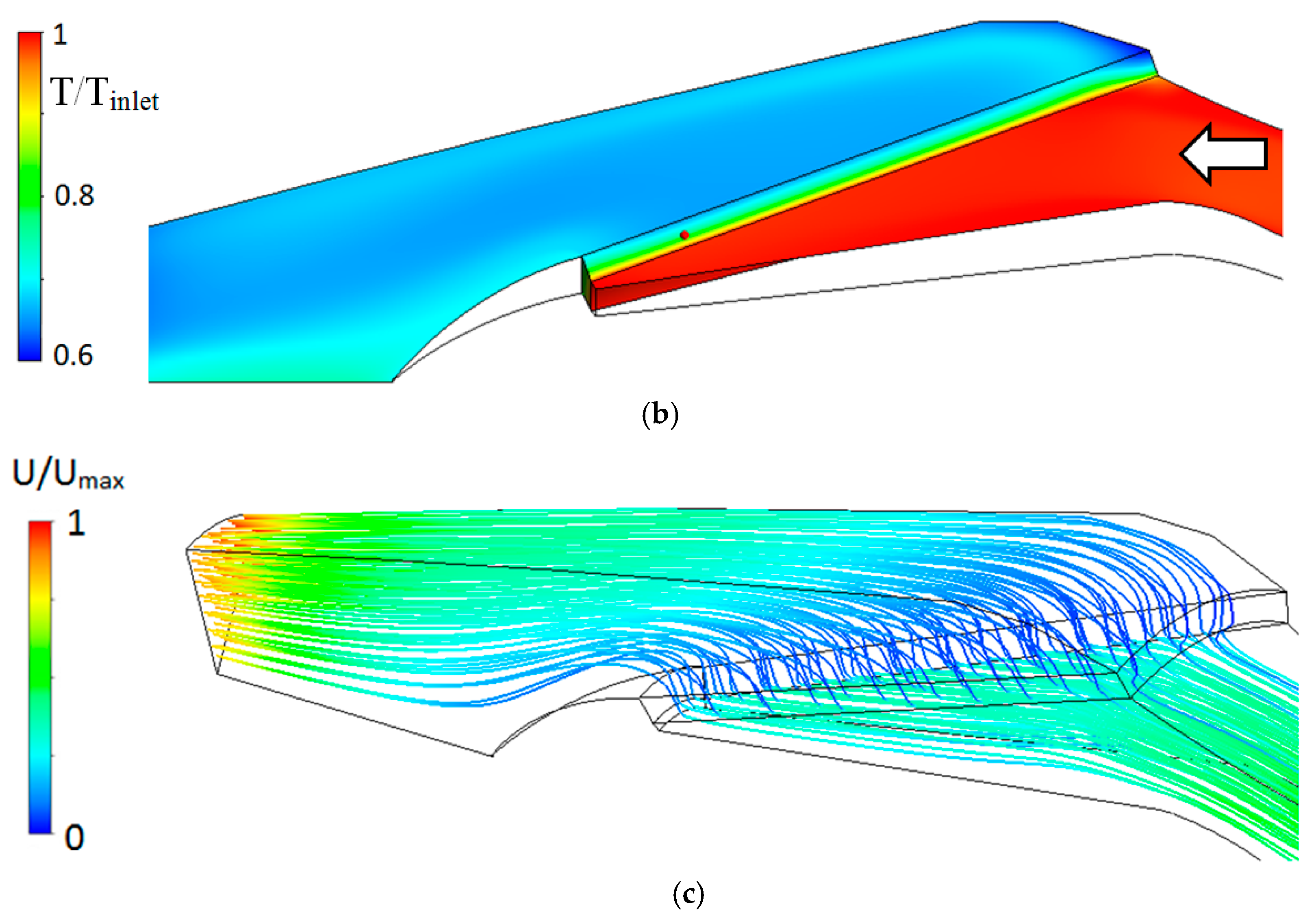
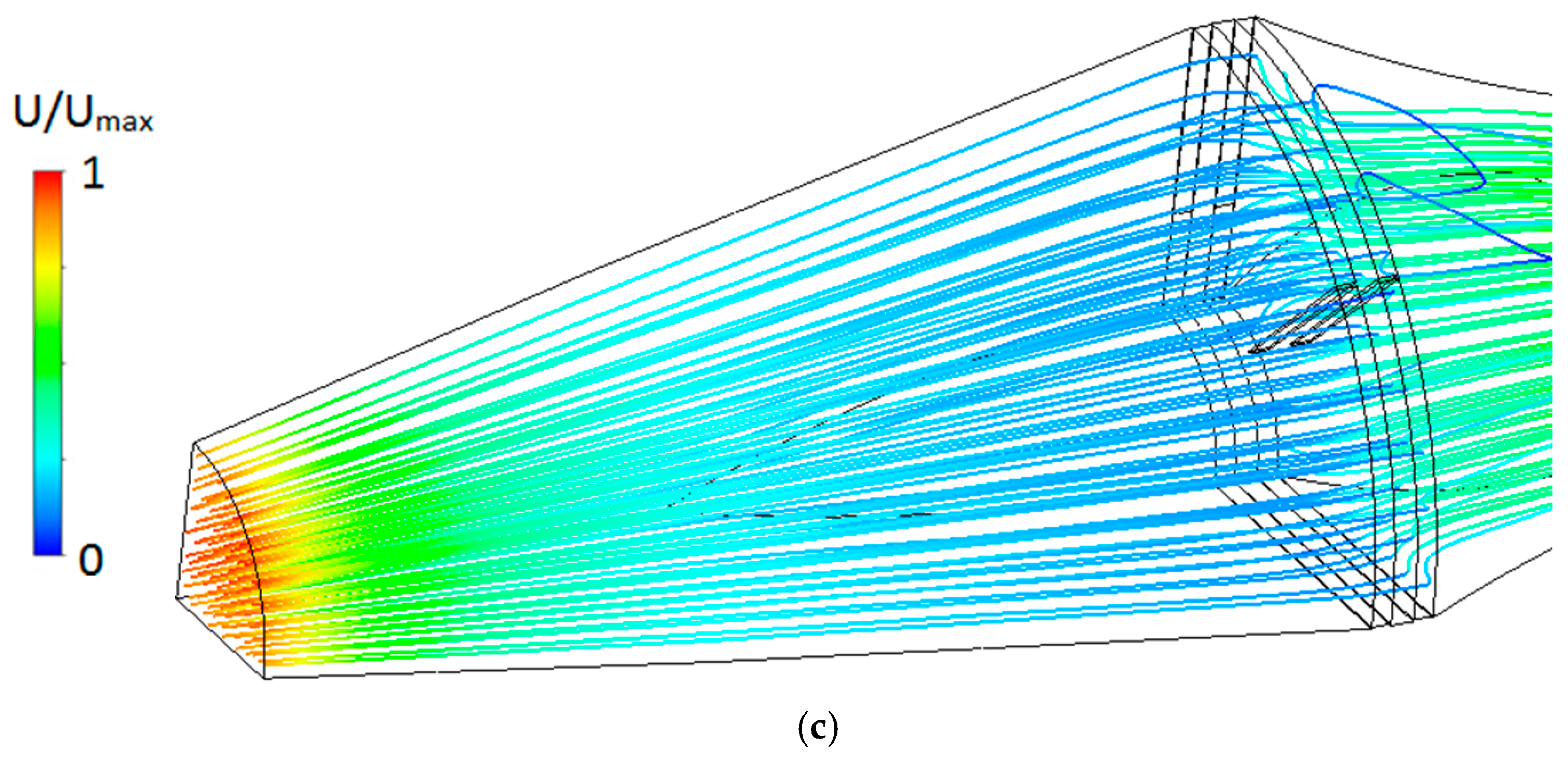
This nozzle configuration corresponds to a quarter of the overall nozzle installation taking into account the symmetric arrangement of the heat exchangers. The NEWAC nozzle configuration consists of four heat exchangers (HEXs) per quarter of the exhaust nozzle. The HEXs 1-2-3-4 are placed at angles 17°-20°-13°-17° in relation to the axial flow direction. The CFD computations were performed using the SST (Shear Stress Transport) turbulence model of Menter, details can be found in [22], in a CFD model of the overall nozzle installation, which is presented in Figure 3b, for a wide range of HEX conditions as presented in [10] in which the heat exchangers’ performance was included through the implementation of additional source terms in the momentum and energy equations. Additional details can be found in [23,24,25]. As it can be seen in Figure 3c,d, strong swirl is formed inside the NEWAC nozzle, which increases the pressure losses and causes a deterioration of the HEXs’ performance and the recuperation benefits in the aero engine cycle. In Figure 3c,d and also in Figure 4, Figure 5, Figure 6 and Figure 7, the white arrow indicates the hot-gas flow after the low pressure turbine. Some additional information regarding the velocity and temperature inside the exhaust nozzle, non-dimensionalized with the inlet conditions, is presented in Figure 4a,b.
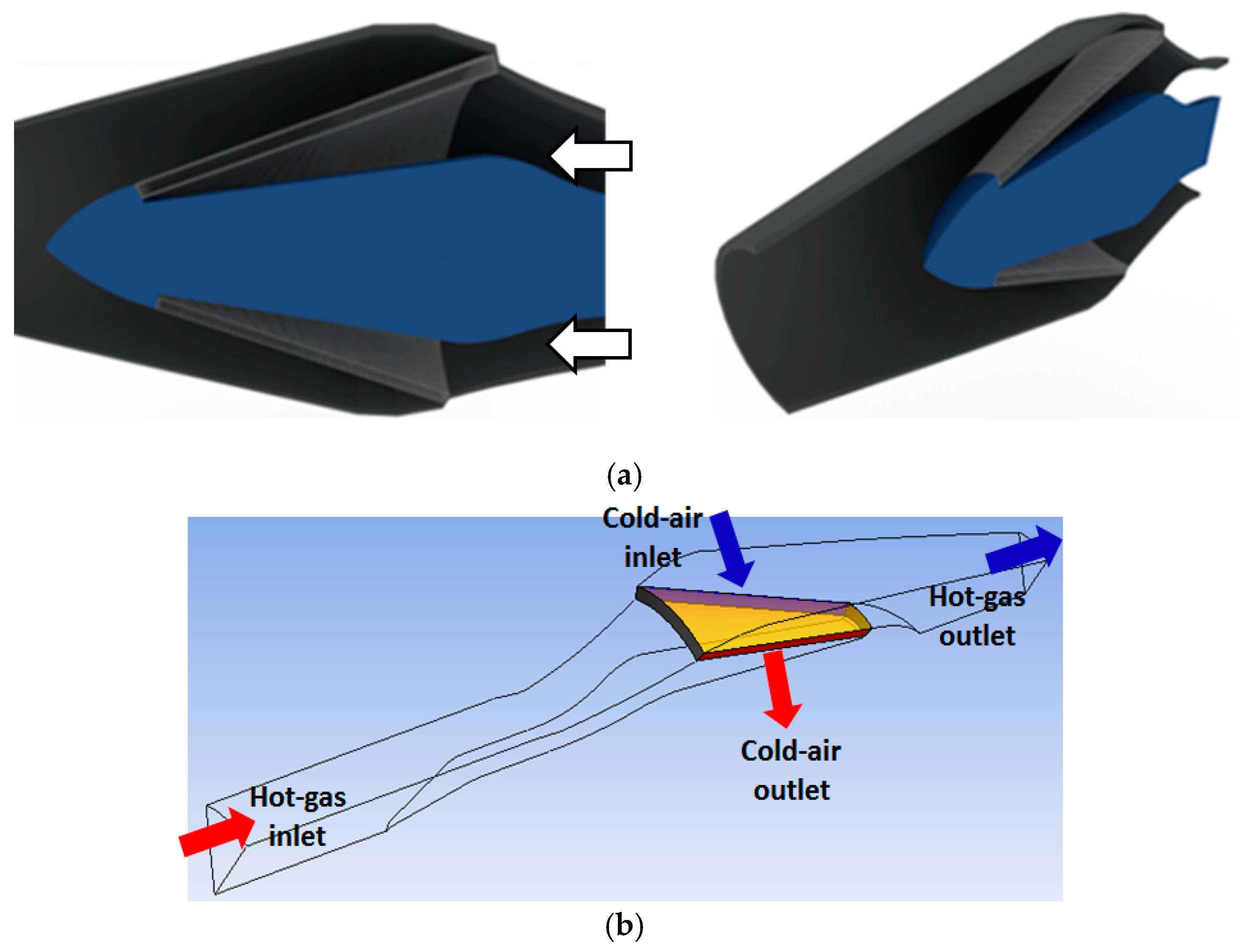
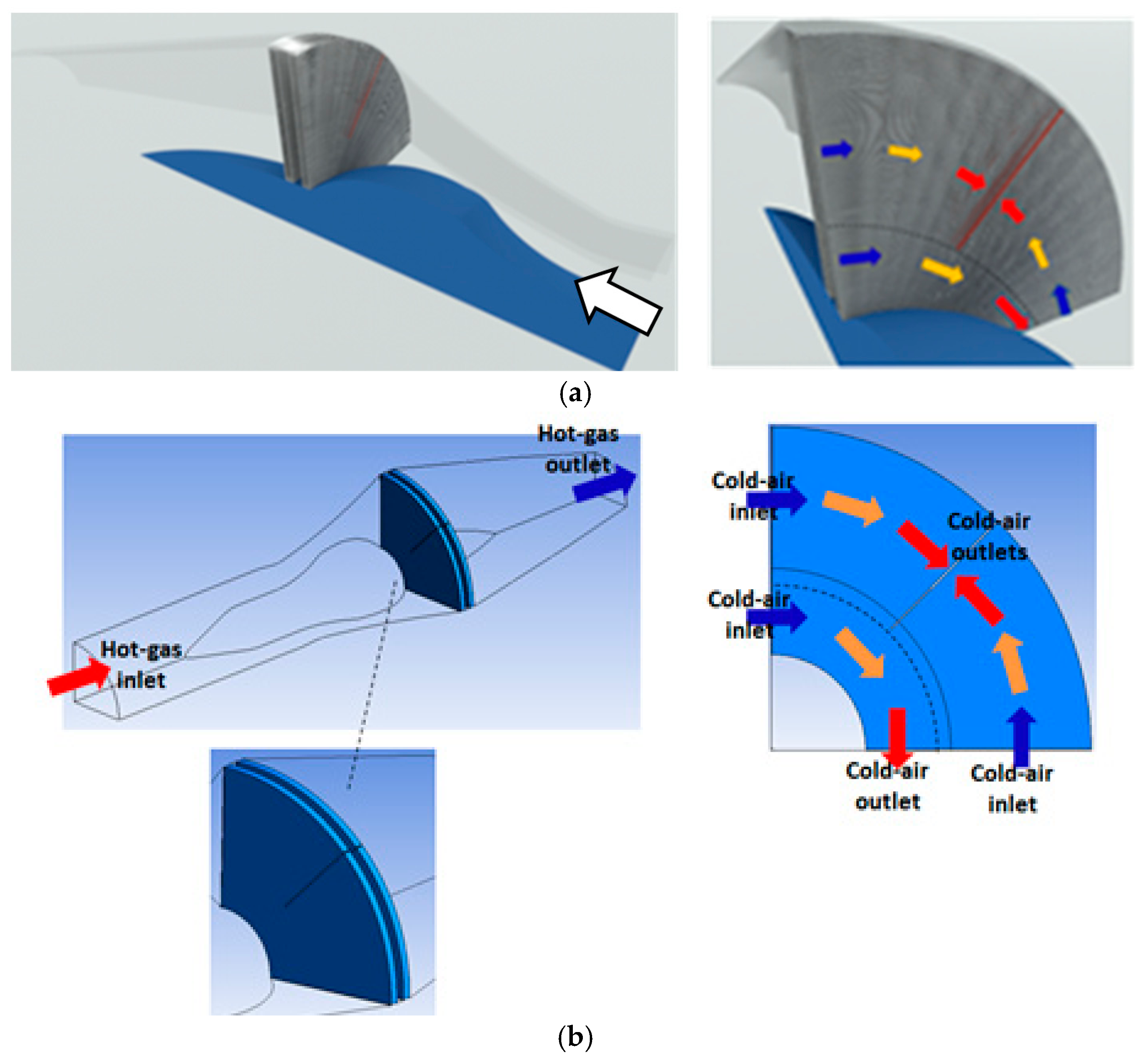
The above was followed by a second step aiming to optimize the HEXs’ installation inside the hot-gas exhaust nozzle, through additional similar CFD computations and the use of the customizable numerical tool. The optimization efforts resulted in two completely new innovative HEX concepts, named as CORN (COnical Recuperative Nozzle) and STARTREC (STraight AnnulaR Thermal RECuperator), presented in Figure 5 and Figure 6 respectively.
Both concepts were based on the MTU HEX original tube geometry. The tubes’ staggered arrangement and the number of rows were optimized through the use of the presented numerical tool. In addition, the number of tube collectors was also optimized in order to achieve the optimum combination of inner flow conditions regarding pressure losses and heat transfer. This resulted in the use of eight tube collectors for CORN and four tube collectors for STARTREC (this concept consists of two banks of different tube core staggered arrangement and density). As a result, in the CFD models, a 45° sector was used for CORN and a 90° sector for STARTREC, as shown in Figure 7a and Figure 8a, by applying appropriate periodicity conditions for the computations.
These concepts were based on the use of innovative heat exchanger designs, following an annular tubes arrangement inside the exhaust nozzle, leading to the reduction (for the STARTREC concept) or complete elimination (for the CORN concept) of swirl effects and achieving a more homogeneous flow distribution with reduced secondary flow losses in relation to the NEWAC nozzle configuration, as presented in Figure 7 and Figure 8.
At the final stage of the study, the basic characteristics of the three heat exchanger concepts (i.e., NEWAC, CORN and STARTREC) were incorporated into GasTurb 11 software [26]. More specifically, the CFD-computed results were incorporated in the calculation of the IRA thermodynamic cycle which is presented in Figure 9, through appropriate coefficients for the inner flow pressure losses (cold-air), the outer flow pressure losses (hot-gas) and the heat exchanger effectiveness. The incorporation of these coefficients in the IRA cycle thermodynamic analysis quantifies the recuperator effect on waste heat exploitation from the hot-gas nozzle for preheating the compressor discharge air before combustion, leading to reduced fuel mass requirement, and the impact of the recuperator imposed pressure losses in both flow currents (inner-cold air, outer-hot gas). As a result, the thermodynamic cycle is properly adapted, from which the necessary data for the calculation of the specific fuel consumption can be extracted from Equation (9) where m ˙ f is the mass flow of the consumed fuel. Additional details can be found in [20].
S F C = m ˙ f T h r u s t
The optimization studies aimed to design optimized heat exchanger concepts for installation in the IRA engine. For the comparison of the results, the main cycle data of the IRA engine were kept the same while the recuperator characteristics were updated each time to correspond to the new proposed heat exchanger characteristics.

4. Discussion

All the CFD results and analysis presented in the current paper aim at the accurate calculation of the different recuperator efficiencies and the accurate quantification of the inner and the outer pressure losses, in order to assess their combined impact on the overall thermodynamic cycle of an aero engine, which will utilize the recuperation technology, such as the IRA engine. As a result, the performance of the three recuperator concepts was quantified and compared in relation to a conventional non-intercooled and non-recuperated aero engine of similar technology level with the IRA. The outcome of this assessment is summarized in Table 1.
From Table 1, it can be seen that the two new recuperator concepts provide significant benefits, in relation to the reference NEWAC recuperator, regarding the specific fuel consumption (SFC) and the weight—two very important parameters for an environmentally friendly aero engine since the SFC is directly related to the aero engine fuel burn and thus, to the pollutant emissions while the recuperator weight is a parameter strongly affecting the implementation potential of this technology.
More specifically, the NEWAC concept resulted in a 12.3% SFC reduction in relation to a conventional non-intercooled aero engine. The further improvement of the NEWAC recuperator and hence the IRA performance improvement, which was materialized by the two new introduced concepts, provided some interesting findings. First of all, the CORN concept showed the best behavior regarding SFC reduction by reaching 13.1% (in relation to a non-recuperated aero engine) and a small weight reduction of ~5% in relation to NEWAC. On the other hand, the STARTREC concept, although it presented an SFC reduction of only 9.1%, provided a significant recuperator weight reduction that can reach 50% in relation to the NEWAC recuperator concept.
The basic advantage of these two new recuperator designs, in comparison to the NEWAC concept, is that due to their optimized geometrical shape, which is based on an annular axisymmetric recuperator idea, they are more suitable for integration in the exhaust nozzle of an aero engine and are thus able to completely eliminate the secondary flow swirl effects, which are a major contributor to the external hot-gas pressure losses. Additionally, they both retain the initial geometrical elliptical tubes’ shape of the NEWAC recuperator, which is an advantage regarding the minimization of external pressure losses since the external (hot-gas) flow separation around the recuperator tubes in the core of the recuperator is minimized and the heat transfer between the two recuperator streams is much more effective. Apart from the external flow, the annular design and the positioning of the internal flow collectors also favor the decrease of the internal flow pressure losses which also affect the SFC reduction.
Regarding the weight reduction, a compromise must be made between recuperator effectiveness, weight and pressure losses. Since the recuperator effectiveness is strongly linked with the recuperator heat exchange surface, a lighter recuperator would have worse effectiveness and as a result would exploit less hot-gas waste energy, but on the other hand would provide a better behavior regarding external and internal flow pressure losses. As a result, a general conclusion cannot be drawn regarding which recuperator design (CORN or STARTREC) is always the optimal since this depends on the specific mission for which the IRA is designed.
Finally, it must be mentioned that the studies and concepts presented in the current work constitute the fundamental basis of new innovative recuperator designs that are currently being further developed and assessed (together with some other new recuperator concepts and designs) within the framework of the Ultra Low emission Technology Innovations for Mid-century Aircraft Turbine Engines (ULTIMATE) Horizon2020 EU project [27], something that also proves the strong optimization potential of the recuperation technology. These studies have, so far, provided new innovative aero engine architectures that will employ the currently evolving recuperator technology and will set the technology level of the year 2050 aero engines. These new aero engine architectures are designed in order to be in line with the ACARE goals which demand greener and environmentally friendly aero engines.

5. Conclusions

In the present paper, the main activities regarding the incorporation of heat recuperation in aero engines, performed in the EU funded LEMCOTEC research project are presented. These activities were focused on the further optimization of the heat exchangers of the recuperation system of the Intercooled Recuperated Aero engine (IRA engine) concept, which was developed by MTU Aero Engines AG. The investigation and the optimization efforts of the present work were performed with the use of 2D/3D CFD computations, experimental measurements and thermodynamic cycle analysis for a wide range of engine operating conditions.
The main activities that can be highlighted in the current work are the following:
  • The optimization procedure of the reference MTU heat exhcanger was based on the development of a customizable numerical tool which can efficiently model the heat exchanger performance regarding heat transfer enhancement and pressure losses minimization, specially designed for aero engine applications.
  • The described numerical tool is based on an advanced porosity model approach where the heat exchanger core is modeled as a porous media of predifined heat transfer and pressure losses behavior. Additionally, the derived porosity model is able to provide accurate results to a wide range of conditions (from laboratory to flight conditions) and to incorporate the major critical recuperator design decisions in the CFD computations, through the coupling of the flow momentum and energy transport equations.
  • The optimization efforts resulted in two completely new innovative recuperator design concepts, named as CORN (COnical Recuperative Nozzle) and STARTREC (STraight AnnulaR Thermal RECuperator). These concepts were following an annular tubes recuperator axisymetric core design inside the hot-gas exhaust nozzle.
  • The proposed recuperators were assesed in a thermodynamic cycle analysis providing improved SFC and significant benefits in terms of pollutants emission and weight reduction in comparison to the original NEWAC recuperator installation of the IRA engine, thus promoting the fullfillment of ACARE goals towards greener and environmentally friendly aero engines.

Acknowledgments

This work is financially supported by the EU under the “LEMCOTEC—Low Emissions Core-Engine Technologies”, a Collaborative Project co-funded by the European Commission within the Seventh Framework Programme (2007–2013) under the Grant Agreement No. 283216. Christina Salpingidou would like to thank Alexander S. Onassis Public Benefit Foundation for the scholarship.

Author Contributions

Dimitrios Misirlis, Zinon Vlahostergios, Christina Salpingidou, Kyros Yakinthos and Apostolos Goulas contributed to the development of the numerical tool, the CFD computations, the thermodynamic cycle analysis, the data post processing analysis and the paper writing. Michael Flouros and Stefan Donnerhack provided industrial feedback and advice, and technical specifications regarding the IRA engine.

Conflicts of Interest

The authors declare no conflict of interest.

Nomenclature

a 0 ,   a 1 Viscous pressure loss coefficients
b 0 ,   b 1 ,   b 2 Inertial pressure loss coefficients
C , m , n Nusselt number coefficients
C 1 ,   C 2 Calibration constants for inner pressure losses
f Pressure loss per tube length coefficient
h o u t e r ,   h i n n e r Outer and inner heat transfer coefficients, W·m−2·K−1
h t o t a l ,   h s t a t i c Total and static specific enthalpy, J·kg−1
L Length of the heat exchanger, m
m ˙ f Mass flow of the consumed fuel
N u ¯ Nusselt number
P t o t _ i n n e r Total pressure of the inner flow, Pa
P r Prandtl number
R e Reynolds number
S e x c h a n g e Heat exchange surface per unit volume of the heat exchanger, m2·m−3
T Temperature, K
T i n n e r Temperature of the inner flow, K
v Kinematic viscosity, m2·s−1
U i Cartesian velocity vector, m·s−1
U o v e r a l l Overall heat transfer coefficient, W·m−2·K−1
u i u j ¯ Reynolds stresses, m2·s−2
u i n n e r Inner “cold” air velocity, m·s−1
x i Cartesian coordinates
Δ P Hot-gas pressure losses, Pa
μ Molecular viscosity, kg·m−1·s−1
ρ Fluid density, kg·m−3
CORNCOnical Recuperative Nozzle
HEXHeat EXchanger
IRAIntercooled Recuperative Aero-engine
LEMCOTECLow Emissions Core-Engine Technologies
NEWACNEW Aero engine Core concepts
SFCSpecific Fuel Consumption
STARTRECSTraight AnnulaR Thermal RECuperator
ULTIMATEUltra Low emission Technology Innovations for Mid-century Aircraft Turbine Engines

References

  1. Bock, S.; Horn, W.; Wilfert, G.; Sieber, J. Active Core Technology within the NEWAC Research Program for Cleaner and More Efficient Aero Engines. In Proceedings of the European Air and Space Conference, Berlin, Germany, 10–13 September 2007. CEAS-2007–055.
  2. Wilfert, G.; Sieber, J.; Rolt, A.; Baker, N.; Touyeras, A.; Colantuoni, S. New environmental friendly aero engine core concepts. In Proceedings of the ISABE 2007 Conference, Beijing, China, 2–7 September 2007.
  3. Low Emissions Core-Engine Technologies (LEMCOTEC) Project Web Site. Available online: http://www.lemcotec.eu/ (accessed on 29 December 2016).
  4. Misirlis, D.; Vlahostergios, Z.; Flouros, M.; Salpingidou, C.; Donnerhack, S.; Goulas, A.; Yakinthos, K. Intercooled Recuperated Aero Engine: Development and Optimization of Innovative Heat Exchanger Concepts. In Proceedings of the 2nd ECATS Conference on Making Aviation Environmentally Sustainable, Athens, Greece, 7–9 November 2016.
  5. Intercooled Recuperative Core Concept. Available online: http://www.newac.eu/uploads/media/Intercooled_Recuperative_Core_Concept.pdf (accessed on 10 February 2017).
  6. NEWAC Subproject 2 “Intercooled Recuperative Core”. Available online: http://www.newac.eu/86.0.html (accessed on 10 February 2017).
  7. Broichhausen, K.; Scheugenpflug, H.; Mari, Ch.; Barbot, A. Clean the European Initiative towards Ultra Low Emission Engines. In Proceedings of the ICAS 2000, Harrogate, UK, 27 August–1 September 2000.
  8. Wilfert, G.; Masse, B. Technology integration in a low emission heat exchanger engine. In Proceedings of the 8th CEAS European Propulsion Forum, Nottingham, UK, 1 March 2001.
  9. Boggia, S.; Rüd, K. Intercooled recuperated aero engine. In Proceedings of the Deutscher Luft- und Raumfahrt Kongress, Dresden, Germany, 20–23 September 2004.
  10. Schonenborn, H.; Simon, B.; Ebert, E.; Storm, P. Thermomechanical design of a heat exchanger for a recuperative aero engine. In Proceedings of the ASME Turbo Expo 2004: Power for Land, Sea and Air, Vienna, Austria, 14–17 June 2004.
  11. Goulas, A.; Donnerhack, S.; Flouros, M.; Missirlis, D.; Vlahostergios, Z.; Yakinthos, K. Thermodynamics cycle analysis, Pressure loss and heat transfer assessment of a recuperative system for aero engines. In Proceedings of the ASME Turbo Expo 2014: Power for Land, Sea and Air, Düsseldorf, Germany, 16–20 June 2014.
  12. Kyprianidis, K.G.; Grönstedt, T.; Ogaji, S.O.T.; Pilidis, P.; Singh, R. Assessment of future aero-engine designs with intercooled and intercooled recuperated cores. J. Eng. Gas Turbines Power 2011, 133, 011701. [Google Scholar] [CrossRef]
  13. Xu, L.; Kypianidis, K.; Grönstedt, T. Optimization study of an intercooled recuperated aero-engine. J. Propuls. Power 2013, 29, 424–432. [Google Scholar] [CrossRef]
  14. Missirlis, D.; Yakinthos, K.; Palikaras, A.; Katheder, K.; Goulas, A. Experimental and numerical investigation of the flow field through a heat exchanger for aero-engine applications. Int. J. Heat Fluid Flow 2005, 26, 440–458. [Google Scholar] [CrossRef]
  15. Yakinthos, K.; Missirlis, D.; Palikaras, A.; Storm, P.; Simon, B.; Goulas, A. Optimization of the design of recuperative heat exchangers in the exhaust nozzle of an aero engine. Appl. Math. Model. 2007, 31, 2524–2541. [Google Scholar] [CrossRef]
  16. Albanakis, C.; Yakinthos, K.; Kritikos, K.; Missirlis, D.; Goulas, A.; Storm, P. The effect of heat transfer on the pressure drop through a heat exchanger for aero engine applications. Appl. Therm. Eng. 2009, 29, 634–644. [Google Scholar] [CrossRef]
  17. Albanakis, C.; Missirlis, D.; Storm, P.; Yakinthos, K.; Goulas, A. Experimental investigation of the effect of heat transfer on pressure drop for a heat exchanger for aero engine applications, ExHFT-7. In Proceedings of the 7th World Conference on Experimental Heat Transfer, Fluid Mechanics and Thermodynamics, Krakow, Poland, 28 June–3 July 2009.
  18. ANSYS 15/Fluent CFD Software User’s Guide. Available online: http://148.204.81.206/Ansys/150/ANSYS%20Fluent%20Users%20Guide.pdf (accessed on 10 January 2017).
  19. Missirlis, D.; Donnerhack, S.; Seite, O.; Albanakis, C.; Sideridis, A.; Yakinthos, K.; Goulas, A. Numerical development of a heat transfer and pressure drop porosity model for a heat exchanger for aero engine applications. Appl. Therm. Eng. 2010, 30, 1341–1350. [Google Scholar] [CrossRef]
  20. Yakinthos, K.; Missirlis, D.; Sideridis, A.; Vlahostergios, Z.; Seite, O.; Goulas, A. Modelling the operation of a system of recuperative heat exchangers for an aero engine with the combined use of a porosity model and a thermo mechanical model. Eng. Appl. Comput. Fluid Mech. 2012, 6, 608–621. [Google Scholar] [CrossRef]
  21. Yakinthos, K.; Misirlis, D.; Vlahostergios, Z.; Flouros, M.; Donnerhack, S.; Goulas, A. Best Strategies for the Development of a Holistic Porosity Model of a Heat Exchanger for Aero Engine Applications. In Proceedings of the ASME Turbo Expo 2015: Power for Land, Sea and Air, Montreal, PQ, Canada, 15–19 June 2015.
  22. Menter, F.R. Two-Equation Eddy-Viscosity Turbulence Models for Engineering Applications. AIAA J. 1994, 32, 1598–1605. [Google Scholar] [CrossRef]
  23. New Aero Engine Core Concepts (NEWAC) Project. Available online: http://www.newac.eu/ (accessed on 29 December 2016).
  24. Yakinthos, K.; Missirlis, D.; Seite, O.; Vlahostergios, Z.; Goulas, A. Modeling the operation of a heat exchanger for aero engine applications for real engine operating conditions. In Proceedings of the 8th International ERCOFTAC Symposium on Engineering Turbulence Modelling and Measurements, Marseille, France, 9–11 June 2010.
  25. Missirlis, D.; Yakinthos, K.; Seite, O.; Goulas, A. Modeling an installation of recuperative heat exchangers for an Aero engine. In Proceedings of the ASME Turbo Expo 2010: Power for Land, Sea and Air, Glasgow, UK, 14–18 June 2010.
  26. Kurzke, J. Design and Off-Design Performance of Gas Turbines, GasTurb 11; GasTurb GmbH: Aachen, Germany, 2011. [Google Scholar]
  27. Ultra Low Emission Technology Innovations for Mid-Century Aircraft Turbine Engines (ULTIMATE) Project. Available online: http://www.ultimate.aero/ (accessed on 10 January 2017).
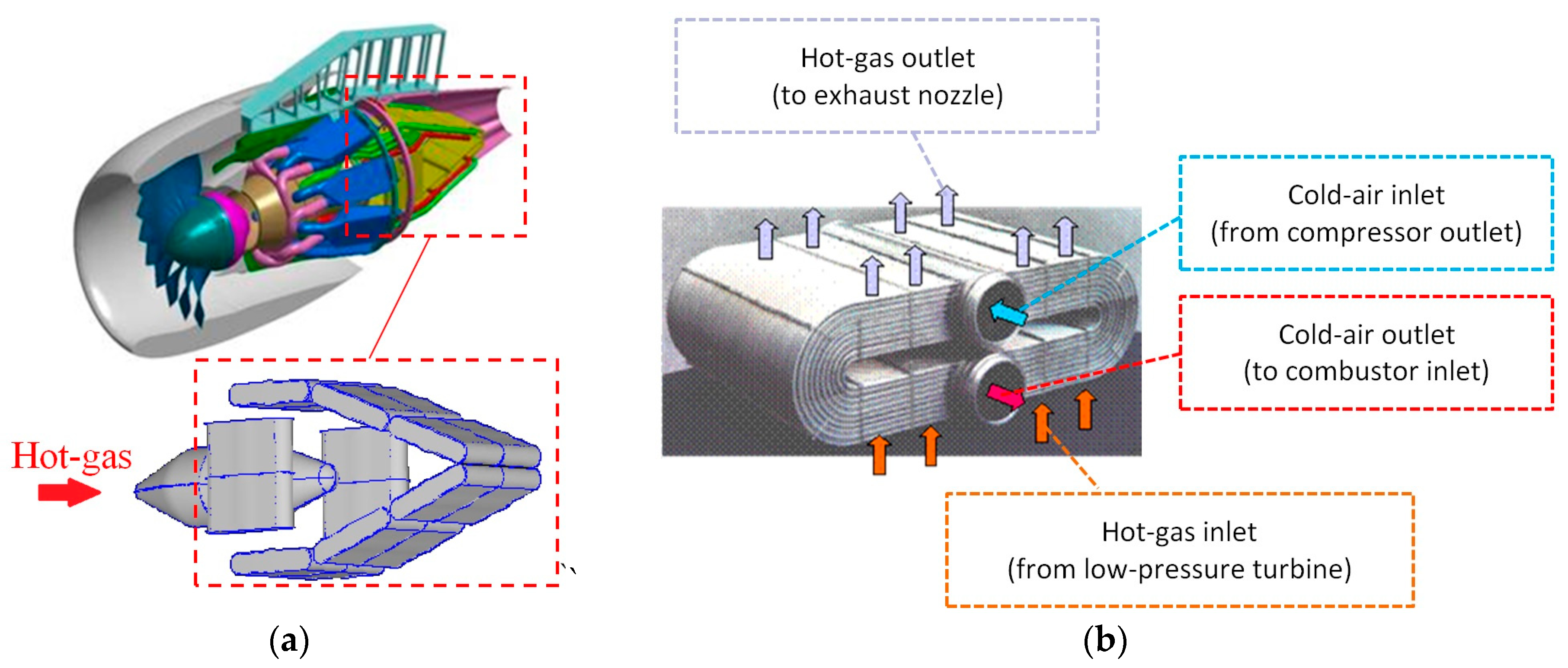
Figure 1. (a) The IRA—Intercooled Recuperative Aero engine [5]; (b) A matrix of the MTU-heat exchanger and the 4/3/4 elliptical tubes staggered arrangement [6].
Aerospace 04 00014 g001
Figure 2. Implementation of pressure loss and heat transfer source terms in the momentum and energy transport equations.
Aerospace 04 00014 g002
Figure 3. (a) NEWAC nozzle configuration; (b) computational grid of the nozzle; (c,d) swirl effects in the NEWAC nozzle, different colors indicate velocity magnitude value configuration (red: high, blue: low).
Aerospace 04 00014 g003
Figure 4. NEWAC nozzle configuration (a) velocity; (b) static temperature non-dimensional distributions.
Aerospace 04 00014 g004aAerospace 04 00014 g004b
Figure 5. CORN (COnical Recuperative Nozzle) (a) geometry and (b) flow currents per 45° sector.
Aerospace 04 00014 g005
Figure 6. STARTREC (STraight AnnulaR Thermal RECuperator) (a) geometry; (b) flow currents per 90° sector.
Aerospace 04 00014 g006
Figure 7. CORN (a) computational grid (45° sector); (b) static temperature non-dimensional distribution; (c) velocity streamlines.
Aerospace 04 00014 g007aAerospace 04 00014 g007b
Figure 8. STARTREC (a) computational grid (90° sector); (b) static temperature non-dimensional distribution; (c) velocity streamlines.
Aerospace 04 00014 g008aAerospace 04 00014 g008b
Figure 9. Thermodynamic cycle in Gas Turb 11 for IRA Engine Average Cruise conditions (a) and schematic illustration of IRA engine basic components (b). The stations numbering is following the standard GasTurb numeration.
Aerospace 04 00014 g009aAerospace 04 00014 g009b
Table 1. Comparative results of recuperation concepts.
CaseSFC Reduction (in Relation to a Conventional Aero Engine)Heat Exchangers‘ Weight Reduction (in Relation to NEWAC)
NEWAC nozzle12.3%0
CORN13.1%~5%
STARTREC9.1%~50%