Review

Testing-Based Approach to Determining the Divergence Speed of Slung Loads

School of Aerospace Engineering, Georgia Institute of Technology, Atlanta, GA 30332, USA
*
Author to whom correspondence should be addressed.
Aerospace 2018, 5(1), 24; https://doi.org/10.3390/aerospace5010024
Submission received: 15 December 2017 / Revised: 19 February 2018 / Accepted: 25 February 2018 / Published: 28 February 2018
(This article belongs to the Special Issue Aircraft Dynamics & Control)

Abstract

:
When a rotorcraft carries an external slung load, flight speed is often limited by the fear of divergent oscillations, rather than vehicle performance. Since slung objects can be of any shape, incorporating the aerodynamics with sufficient accuracy to predict safe speed has been a problem. The uncertainty forces certifying authorities to set conservative limits on speed to avoid divergence. Obtaining the aerodynamic coefficients of bluff bodies was excessively time-consuming in experiments, and impractical in computations. This review traces the evolution of progress in the area. Prior thinking was to use computations for prediction, with the computational codes validated using a few samples of experiments. This approach has not led to valid general predictions. Data were sparse and a-priori predictions were rarer. A continuous rotation approach has enabled swift measurements of 6-degrees-of-freedom aerodynamic load maps with high resolution about several axes of rotation. The resulting knowledge base in turn permits a swift determination of dynamics up to divergence, with wind tunnel tests where necessary to fill interpolation gaps in the knowledge base. The essence of efficient and swift dynamics simulation with a few well-tested assumptions is described. Under many relevant conditions, the vehicle flight dynamics can be safely decoupled from those of the slung load. While rotor wake swirl causes the payload to rotate at liftoff and landing, this effect can be incorporated into the simulation. Recent success in explaining two well-documented flight test cases provides strong evidence that predictions can be made for most missions swiftly.

1. Introduction

Rotorcraft such as helicopters are often used to transport a wide variety of objects [1,2] slung underneath. Such operations are used in carrying buckets of water to fight fires [3], transport emergency supplies, ferry road vehicles and even to ferry people rescued from floods. Such operations are distinguished, for the purposes of this mini-review, from operations where objects or people are simply winched up to or down from helicopters: in such cases, there is no need for fast vehicle movement. The objects carried as slung loads are typically not aerodynamically streamlined, but instead they are bluff bodies with flow separation being a constant reality. The object may take any attitude towards the oncoming wind because of roll, pitch and yaw oscillations. The tethers may be cables or chains. Tension typically holds these tethers quite stiff, with little elastic oscillation. Speed is often limited not by vehicle performance, but by the danger of the slung load going into large-amplitude or even divergent oscillations that threaten vehicle safety [4]. In recent years, slung loads appear to have been used extensively in delivering supplies to besieged areas in Syria, as well as in Afghanistan and Iraq, flying over hostile terrain. Published articles on these are as-yet difficult to obtain. Pilot anecdotes reveal the extreme importance of speed as well. They cite the uncertainty in monitoring slung load dynamics in night operations, where the crew must use night-vision goggles to observe the dynamics. These goggles typically have narrow fields of vision so that monitoring requires constant head movement from a maneuvering helicopter.
The decision to certify the highest safe speed for a given mission has difficult constraints. Specify too low a limit, and lives may be lost due to delay in reaching people, or because the vehicle did not complete the transit before hostiles were able to set up weapons. Too high a limit might cause a fatal accident, leading to the loss of both the rescuers and those awaiting help. In most cases the preferred outcome would be to allow operation up to the speed specified by the manufacturers for the vehicle with a given load weight, for the expected weather conditions and altitude. With lighter, less dense loads such as an empty water bucket, empty engine canister or water tank, or a component of a ribbon bridge used to erect floating bridges across rivers, the weight of the object may be too low to limit the vehicle flight speed. However, the aerodynamic forces can become large enough to overwhelm the inertia of the object and drive it into unstable oscillations, leading to collisions with the vehicle structure, or the deadly possibility of impacting the tail or main rotor.
Speed is a value proposition in many slung-load operations [5]. Survival over hostile areas within missile and rocket-propelled grenade altitudes requires the highest speed possible. In civilian operations the classic example is firefighting. Helicopters are often called to fight forest fires [6], as well as large industrial fires [3]. It is important to deliver the maximum amount of water in the shortest possible time on a fire. The cost of bringing a large helicopter is much higher than that of using smaller helicopters. Thus an objective of firefighting organizations is to increase the amount of water that can be delivered by smaller helicopters. One way is to increase the speed of the return trip with an empty bucket to get more water. High speed runs the risk of a tail rotor strike [7], as the bucket can swing far back due to drag, as well as amplified coning motion. Stuckey [8] mentions an inflatable boat striking the front of a CH-47 aircraft, obviously due to amplified pitch oscillations.
The approach to certification [9] has traditionally been to test [10] combinations of objects and vehicles, where there is reason to suspect that flight at the vehicle performance limits might be dangerous. However, the number and variety of objects to be carried [1], along with the number of different carrier vehicles, impose an ever-rising number of combinations, far beyond the time and budget constraints of certifying organizations. Faced with this problem, there has been considerable effort to develop certification methods based on some combination of computational aeromechanics prediction and testing. Wind-tunnel and flight testing has been viewed as being limited to providing a few samples to validate the prediction codes. Recently, interest in a certification approach based on wind-tunnel experiments, validated by flight tests, has been advanced. In this mini-review, advances along this approach are summarized, along with other approaches.

2. Review on Approaches to Slung-Load Aeromechanics

2.1. Flight Test Data

Flight test data are rarely available in the open literature, partly because the objects of interest, and the vehicles that carry them, are military vehicles. A few cases are available. Cicolani et al. [11,12,13,14] have reported extensive flight tests with the cuboidal configuration called the Container Express (CONEX) container and one case of a cylindrical engine canister. Thompson and Thorpe [15] describe flight test data on an empty engine canister carried as slung load. The test was stopped when the intermittent pitch excursions of the canister came too close to the tail rotor. These data have been successfully matched by simulations from the authors’ research group, as discussed later. Another flight dataset is available on a ribbon bridge model [16].

2.2. Wind-Tunnel Data

Bluff body aerodynamic measurements typically involve nonsymmetric attitudes, where aerodynamic loads are experienced about several or all six degrees of freedom. Although drag has traditionally been of most interest [17], side force and yawing moment become very important in determining the amplification of slung load motions. Measurements about multiple axes have been reported in the literature since the early days of aerodynamic measurements in wind tunnels [18,19,20,21,22,23,24,25,26,27,28,29]. The traditional wind tunnel balance was optimized to handle objects with large lift-to-drag ratio [30,31,32,33,34]. Thus the sensitivity of the drag sensor had to be large. When used with bluff bodies, such balances were limited in their range, and suffered large interaction errors. The occurrence of arbitrary attitudes in bluff body applications also implies the need to sweep through many attitudes, with the possibility that sharp variations might occur over small changes in attitude. Measurements over many attitudes were obtained, but then averaged, in [35] in studying sports balls. Measurements with continuous spin and pitch have been used in studying the dynamics of missiles in dynamics wind tunnels [31,34,36]. Such methods are still limited in the amount of data that can be generated efficiently [37].
Extensive measurements of bluff body drag have been conducted at a few wind tunnels, beyond the usual studies of two-dimensional circular cylinders in cross-flow. Among those are the Technion wind-tunnel measurements that have been used in slung load development [38,39,40,41,42,43,44,45,46,47]. Surveying these, typical practice appears to be limited to obtaining force coefficients at a very few attitudes, for example, 15 degrees azimuthal resolution over 90 degrees of rotation, assuming symmetry to fill in the data for the other three quadrants. From the data it appears that Reynolds number effects are minimal once into a regime where transition may be expected (over 100,000 based on a typical dimension). Drag coefficient values in general appear to be not far from those values predictable from the 3-D flat-plate drag coefficient based on the cross-sectional area of the object at each condition. As a result, the authoritative reference by Hoerner [17] continued to be the best resource for engineers who had to come up with quick estimates. Examples of studies relevant to the current interest on static circular cylinders are mentioned by Roshko et al., Matsumoto et al., Komatsu et al., King et al., Barnes et al., Bearman et al., Bentley et al., Wei et al. and Nakamura et al. [41,48,49,50,51,52,53,54,55,56]. Matsumoto [49] observed both damping and divergent oscillations of the vibrations of long rectangular cross-section bars, due to vortex shedding, including torsional vibrations.
When the payload spins, the spin can significantly affect stability. The rotations encountered in practice are generally in the static/quasi-steady regime of unsteady aerodynamics, as seen quite easily. Spin is induced at the start of a slung-load flight by the swirl in the wake of the rotors, and hence occurs when the vehicle lifts off and climbs, and also as the vehicle comes in for landing. As the vehicle transitions to forward flight, spin generally slows down or stops. When spin occurs again, this can have serious effects. One caution is in order here. In wind-tunnel tests without a rotor wake present, model spin and amplification of roll have been reported by some researchers, and this has been viewed as agreeing with flight test observations. This is probably due to tunnel-wall effects. Sharma et al. [57,58] studied this problem with a simple mathematical formulation using doublets to represent the forces acting on the model. They showed that spin and roll disturbances reinforced each other when the phase difference between them approached 90 degrees, and the amplification depended strongly on wall effects. In other words, where wall effects are negligible, spin disturbances do not amplify on symmetric models at low speeds. At significantly higher speeds they may amplify along with roll.
The Magnus effect produces lift on spinning bodies in a flow. Swanson [59] reviewed progress in understanding this effect. In the case of bodies with non-smooth surfaces with sharp features, such as a helicopter rotor hub, such effects are generally not significant. In the case of bluff bodies carried as slung loads, the spin rate is quite low as mentioned above, with the aerodynamics limited to the quasi-steady regime. However, spin can be both stabilizing and destabilizing. At low spin rates, spin is generally destabilizing because it can cause phase differences or subharmonics of the roll, which can then amplify over several cycles. At higher spin rates, spin is stabilizing, as the gyroscopic effect increases, and the rate is high enough to go through several different phase relationships with roll within a single roll oscillation. Some rotorcraft operations are conducted with the tethers attached to a point that does not permit free spin. Under these conditions the tethers can twist around each other, and constrain the rotation, causing it to reverse. This is preferred where operators are concerned about free spin making it difficult to land a payload. However, the experience reported by researchers (no published reference available) is that a free-to-spin bearing increases the divergence speed, and is hence a safer option for high-speed slung-load operations. We note that the effect of the rotor wake swirl causing loads to spin at liftoff is easily incorporated as an initial condition in dynamic simulations as the vehicle accelerates.
Curiously, the case of circular cylinders of small aspect ratio (below 4) at yaw appears to have not been studied beyond the work performed by Zdravkovich et al., Szepessy et al. and Norberg et al. [42,43,60,61]: these led to interesting revelations about the realities of computational ‘prediction’ practices where operators appeared to be downloading published results with little physical insight, and adjusting their grid generation and turbulence models until the results matched the downloaded experimental results at only the points published in the experiments. The paucity of intermediate results and the opacity of the operations, rationalized as being required by government rules, make it impossible to place credence on such an approach to prediction.

2.3. Dynamics Analysis

Analytical studies of helicopter slung-load dynamics have been conducted all over the world. Sheldon [62] studied the different cases of tandem and lateral dual-point versus single-point suspensions. Nagabhushan [63] conducted a thorough mathematical analysis of the dynamics of slung loads. Other and more recent work has come from [10,64,65,66,67,68,69,70,71,72,73,74,75]. Stuckey [8,76] revisited the problem with a comprehensive mathematical formulation.

2.4. Computational Analyses

Given the high difficulty of running wind-tunnel experiments to capture 6-degrees-of-freedom (DOF) aerodynamic coefficient maps over all possible orientations, the traditional hope has been that high-resolution computational fluid dynamics (CFD) codes will enable predictive calculation of bluff body pressure distributions which can be integrated to yield 6-DOF aerodynamic coefficients. Given the fast pace of advancement in computer speed, it appears reasonable to expect that the full time-dependent Navier–Stokes equations, applied with uncompromising rigor to model the entire configuration (including supports and walls in the case of wind-tunnel data) along with carefully specified free-stream turbulence and model surface details and texture, should yield the correct aerodynamic coefficient map. In this scenario, the presumed advances were in computational power, translated to speed and resolution, along with research on turbulence modeling starting with large eddy simulation (LES) and eventually leading to direct numerical simulation over the entire turbulence spectrum of scales and frequencies. Such codes also offer 6-degrees-of-freedom modules, where the dynamics of an object can be tightly coupled into the aerodynamics, at the time-step level. This is often referred to as the field of computational fluid–structure interaction, involving coupled operation of computational fluid dynamics (CFD) and computational structural dynamics (CSD) codes. It differs from approaches where the aerodynamics are determined independently of the dynamics simulation.
Not surprisingly, computational codes capable of such resolution, and access to computers capable of running these at the required speeds continues to be restricted due to security and technology-transfer concerns. In other words, the methods used are rarely transparent for other researchers to challenge or examine in the open literature. Even undergraduate students participating in some research groups that run such codes are required to sign non-disclosure agreements that prohibit discussion of the practices followed. These aspects are stated here because some of the results from the above approach are curious. Of course, research ethics ensures that the vast majority of researchers endeavor to follow the best practices, cognizant of the above concerns. Blind predictions are often conducted, where the experimental data are not revealed until after prediction. Policing such practices lies with individual institutions. The state of the art in computational prediction of bluff body fluid dynamics appears to be quite immature as yet, per discussions with the original developers of the most comprehensive among such codes. The presumed and cited reasons include the difficulty in generating suitable grids, which must still use adaptive techniques. This typically requires operator intervention based on observing intermediate results. Another cited reason is the lack of generality in turbulence models [77], given the wide variety of flow phenomena encountered in bluff body flows. Given these two large uncertainties, one cannot be sure if there are other difficulties. Computational work on problems relevant to slung loads includes the work published by Bonhaus et al., Theron et al., Mantri et al. and Prosser et al. [78,79,80,81]. Free-swinging dynamic behavior on the CONEX container in the wind tunnel was reported in [82], correlating to earlier published data. During this time, the narrative was that if CFD agreed with presupplied experimental data with the tunnel walls and support structure included in the CFD grid, then CFD could be trusted to obtain reliable results for the isolated model in free air, and to extend the Reynolds number range beyond the reach of experiments. When it became evident that CFD results obtained in the absence of presupplied data or published results showed very large errors even for simple shapes, there was no longer any basis for believing CFD results that claimed to include detailed wall and support effects. Hence the above approach had to be abandoned. Wall effects and support interference had to be evaluated independent of CFD.

2.5. Need for Comprehensive Analyses

The general problem includes maneuvering rotorcraft, elasticity of the tethers, the effect of the rotor wake on the slung load, and the effect of the swinging load on the dynamics of the vehicle. Ideally, one requires the aircraft state coupled with that of the slung load at all times to predict the dynamics of both. The results may be expected to vary from one rotorcraft to another, and depend on the thrust and maneuver states of the vehicle as well. Any simplification from this must be validated to ensure that extreme events do not occur in regimes ignored by the simplification. Notable efforts along this route include the published work by Stuckey et al. and Oktay et al. [8,74,76]. Generally, the default approach to such a problem involves coupled operation of a comprehensive code that models the vehicle, and a slung-load aeromechanics module that itself includes a high-fidelity unsteady Navier–Stokes computational fluid–structure interaction modeling code. Such a capability does not exist in practice. A simplified knowledge-base approach is discussed in comparison to the comprehensive analyses in the latter part of this paper.

2.6. Control Approaches

Given the slow progress on the problem of bluff body aerodynamic coefficients, engineers have sought to reduce uncertainty through adaptive control. This has led to a large volume of work, which we can only touch here by referring to recent work. Passive stabilization continues to be studied using rotation of CONEX containers, as used by Cicolani [16]. Their group has also studied active stabilization using deployable vanes attached to one side of the container. Another passive stabilization approach is that pursued by the Natick Soldier Center group, where drag devices are attached to the tethers to damp out oscillation. Beard [83] summarized quadrotor dynamics and control. Control of quadrotors in maneuver with slung loads is described in [84]. Ivler [85] and Lee [86] describe a cable angle feedback control system for slung-load operations. Quadrotor control by input shaping [87,88] and sliding mode control [89] have been explored. Other work on quadrotor control includes the work by Palunko et al., Mo et al., Oktay et al., Nonnenmacher et al., Pereira et al., Pollini et al., Raptis et al., Tartaglione et al., Vargas et al. and Zuo et al. [74,75,90,91,92,93,94,95,96,97,98].

3. Status Summary and Evolution of Approach

The above discussion summarizes the state of technology and thinking in the field of slung-load aeromechanics as of a few years ago. Fundamental difficulties included the following:
  • There is a very large and rising number of combinations of flight vehicle and slung objects, where certification of the limiting speed must be performed and available for each mission.
  • The full problem involves two-body dynamics (3 in the case of artillery pieces that have their ammunition slung below the weapon) of the vehicle and the slung load.
  • Prediction of the aeromechanics of a slung load was presumed to require a coupled fluid–structure interaction high-fidelity computation.
  • High spatial and temporal resolution was required from the computational grid because of the complex geometry and the high Reynolds number.
  • Wind-tunnel experiments provided a low-cost but tedious avenue to provide datasets to validate computational fluid dynamics codes at moderate Reynolds numbers, with limited flight experiments to validate high-Reynolds-number flight conditions.
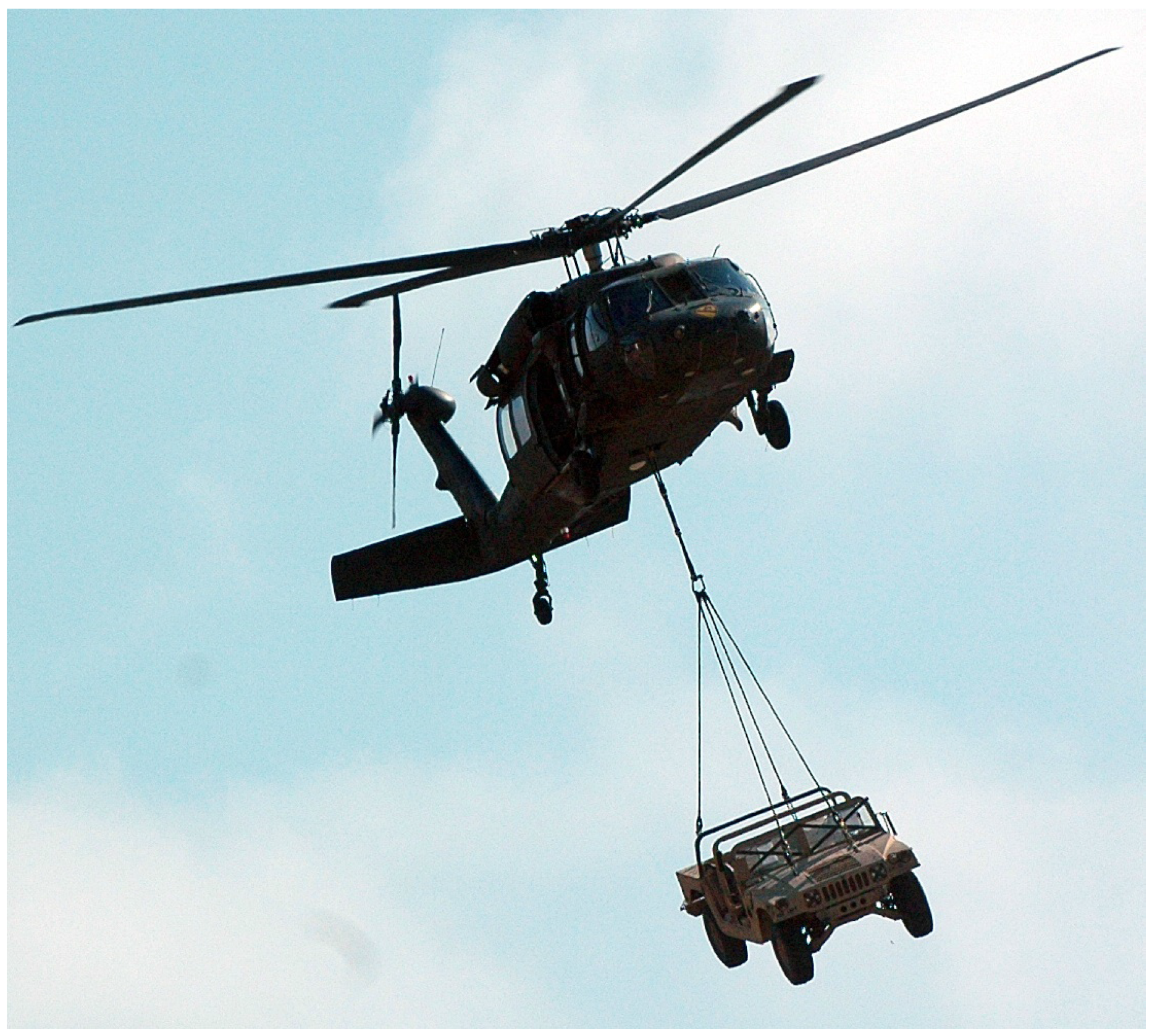
Some of the problems can be seen by considering Figure 1 from Gibson et al. [99]. The geometry of the payload can be complex, with smooth, oblique and sharp-edge separation, cavity flows, surface roughness and dents, shear layer interactions and so on. These lead to large gradients of force and moment about some attitudes. Changing drag with attitude can drive yaw and pitch oscillations. Rotor wake swirl impinging on the object at liftoff can set the object spinning, and turning of the vehicle trajectory can drive roll or coning oscillations. Coupling between these perturbations can amplify motion in any degree of freedom. Thus, aerodynamic loads must be mapped with fine resolution. The resolution of support interference, blockage and so on was left to CFD in work that we reported in the past [80]. This proved unsatisfactory for various reasons discussed above.
One approach is to use a full-physics simulation including coupled fluid–structure interactions, attempting to model all aspects with fine resolution. This is illustrated on the left side of Figure 2 by Hiremath et al. [100] . From the author’s perspecive, this is a long way and time from yielding useful results. Over the years, the inability to predict the fluid dynamics of even simple shapes, such as a smooth small-aspect-ratio cylinder in yaw, became quite evident. Computational power was then devoted to so-called reduced-order modeling, where the aerodynamics model was sought to be derived from flight test data. Unfortunately, this process yields non-unique answers, and nonphysical claims such as hysteresis and rate effects that proved unsustainable by contemplation of basic unsteady aerodynamics theory (the reduced frequency is far too low) as well as by comparison with experiments.
On the other hand, once the aerodynamic coefficient map is known, the problems can be simplified and solved in a time-efficient and reliable manner. This is the basis for fast simulation and on-the-fly safety assurance. Discussion of the process illustrated schematically on the right side of Figure 2 can now be resumed. For a new slung-object–vehicle combination on an urgent field mission, the aerodynamic load map of the object can be immediately interpolated from the bluff body loads knowledge base to predict divergence speed by fast dynamic simulation, of course with a conservative margin of error imposed, of about 5 to 10 percent in divergence speed. Whereas in the past such a guess would be limited to the field engineer’s judgement, or drag estimates from sources published by Hoerner [17], today the interpolation can be done using a laptop computer from the published knowledge bases of Fourier series coefficients for similar body shapes. The work of Motahari [101] explains initial efforts in this direction, where the load map of a new configuration (a road vehicle) was guessed as a 70% to 30% combination of two simple generic shapes where data existed. This produced surprisingly good approximations of the drag and side force variations with azimuth, but did not work satisfactorily for yawing moment variation with azimuth. Queried on why the 70–30 split was chosen, the answer from the researchers, experienced at viewing many such data results, was that they could not explain, but it seemed a good guess. This suggests that in future, automation can be gradually improved to produce more reliable estimates. Motahari [102] discusses the implications for a certification process that is based on a sequence of steps, proceeding from such initial guesses, to results based on specific scale model tests and detailed simulations. Motahari [103,104] presents cases where such a sequence was followed, for complex shapes. Recently, Komerath et al. [105] published a detailed presentation of the experimental techniques to deal with bluff body airload characterization, and Komerath et al. [106] has begun the process of publishing the detailed datasets from canonical cases. In summary, when presented with a completely new configuration, an initial interpolation of data can be performed from generic cases, and used promptly in a dynamic simulation. The estimate of divergence speed by this process will of course have significant uncertainty so that a conservative figure must be given for divergence speed. The aerodynamic load estimates are then verified as time permits, against model-scale wind-tunnel tests. With 3-D modeling and printing techniques, and the continuous rotation technique, this process can be completed in a few days. The uncertainty in divergence speed can then be narrowed further, down to that needed in order to provide for gust encounters or rapid maneuvers when flying near the divergence speed.

4. Simplified Problem Statement

From the above considerations, a simplified problem statement was developed as follows.
  • Froude number scaling holds accurately between flight tests and wind-tunnel tests, across a wide spectrum of Reynolds numbers. This is primarily due to the bluff body shapes with sharp edges used in validation. Some doubt remained about smooth-surface separation and vortex shedding from cylindrical tanks.
  • Military experience indicates that for loads that are less than 1/3 of the gross weight of the vehicle, the effects of the dynamics of the swinging load on the vehicle dynamics are minimal. Thus, slung-load dynamics can be decoupled for a first iteration from those of the vehicle. This assumption is usually satisfied with human-piloted rotorcraft since either the external load capability, or the flight speed, is limited by performance. Obviously the assumption may be violated in case of violent oscillations, but the purpose of prediction is to stay at speeds where such oscillations cannot occur.
  • The Froude number results lead to the belief that aerodynamic coefficients obtained in wind-tunnel tests should be reasonably representative of high-Reynolds-number flight results, once tunnel-wall and support interference effects are held to negligible levels.
  • The frequencies and rates encountered in slung-load operations stay well within the regime of low-reduced-frequency, quasi-steady aerodynamics.
  • Structural deformations such as tether elastic deformation are negligible, and tethers may be assumed to be rigid. Two exceptions occur: the first is when the tethers wind up in cases of rigid mounting points, and the second is where the oscillations become violent. The first regime is typically limited to hover and low-speed operation where the wake swirl causes steady yaw in one direction. For high-speed flight, experience shows that having a free-to-spin bearing at the attachment point enables operation to significantly higher speeds. The other regime must be avoided by staying below the speed where significant amplification occurs.
Simulations with simplifications have been performed by Bisgaard [70] who studied the effects of tether length, Micale [64] who examined gyroscopic stabilization, Fusato [73] who studied turn rate effects, Tyson [68] who used prediction models for bluff bodies with fixed separation points and static load estimates, and Reddy [66] who used dynamic loading with fewer degrees of freedom. With the above simplifications, it is enough to have a well-resolved knowledge base of aerodynamic coefficients over the entire range of possible attitudes of the object. The dynamics of the object under wind load, given an initial perturbation, can be simulated with rigid tethers, assuming a fixed or accelerating attachment point. Furthermore, it is sufficient for this knowledge base to be obtained with quasi-steady aerodynamics. These realizations drove development of the method described in the rest of this review.

5. Continuous Rotation Method

The problem of measuring aerodynamic coefficients of a bluff body with fine azimuthal resolution for all orientations about one axis was first considered. The traditional wind-tunnel testing approach is difficult for the following reasons:
  • Models with sharp edges and flat sides may be highly sensitive to yaw, and this is key to understanding the onset of interactions causing instabilities. This requires many yaw points to define slopes and transitions.
  • For each yaw setting, the model must be set precisely at a given attitude for data acquisition, and the attitude verified. This requires accounting for support deflection under load.
  • For the above reasons, data come with non-uniform spacing, requiring a lookup table and interpolation of doubtful validity during dynamic simulation. This is because sharp changes can occur, for instance in side force and moments, over a small change in orientation. For instance, if one interpolated from 8 degrees to +8 degrees angle of attack, for the lift coefficient of a sharp-edged flat plate, a 16-degree interval typical of those used in bluff body wind tunnel tests and computational fluid dynamics (CFD), one might entirely miss the region of greatest importance to aerodynamics. Most cases are not that extreme, but we do not know enough yet to generalize and be sure.
  • Symmetry assumptions are generally not valid.
  • Reynolds number effects are hard to predict.
  • Interactions between degrees of freedom are hard to predict.
In the past, mounting a motor on top of a balance in the wind tunnel was feared to cause vibrations and failures. However, Forbes et al. [107] used this approach to measure the forces on a rotor hub, spinning at 240 RPM, with a stepper motor mounted on a 6-DOF load cell [28,108]. The data showed no contamination by stand vibration, and capturing yaw loads from the reaction of the motor at the load cell also worked accurately. This knowledge was used to design an experiment where a bluff body shape was rotated very slowly (0.99 revolutions per minute) with the motor placed on a 6-DOF load cell. A typical setup is shown in Figure 3. Data from all six channels were acquired at a high rate, then sorted into the azimuth interval where each datum was acquired. By running the experiment for 10 revolutions, which is long enough to capture the slowest changes occurring in a large closed-circuit wind tunnel, enough data were acquired within each 1-degree azimuth interval. The data proved to be consistent, with little scatter. Sharp gradients were captured. These data were then Fourier-transformed, to generate Fourier series with thousands of terms. By trial and error, it was found that truncating the series beyond 20 terms was sufficient, in most cases, to capture the sharpest excursions in the original data with excellent fidelity. The sufficiency was verified by comparing the azimuthal variation of each load coefficient, generated from the truncated series, with the original data. In only one case to date has the number of terms had to be increased, and in that case it was increased to 50 to be sure of accuracy. Thus the variation of each aerodynamic coefficient about a given axis was represented by a 20-term complex Fourier series. Such a series is basically an analytical expression consisting of sines and cosines, suitable for very fast calculation during a time-step of a simulation. By repeating the experiment about several axes, a much more complete aerodynamic coefficient map could be generated, the sweep about each axis taking only 10 min at each selected tunnel speed. This is many orders of magnitude faster, and far more efficient, than the prior procedures of setting and locking attitudes for steady data acquisition. Specific experiments were performed where the results from the continuous rotation method were compared with data at specific azimuths obtained by holding the model static at those attitudes. The results agreed accurately, as expected. The experiments were also repeated with rotation rates up to 5 RPM, in other words, five times the prescribed rate of 1 RPM. There was no error. This is not surprising, since the reduced frequency of the rotational motion is still extremely low. For rotation rates above 5 RPM, the power of the stepper motor became inadequate. Experiments to study actual rate effects with high rotation rates remain to be performed.

6. Divergence Prediction

Given the availability of such an aerodynamics knowledge base, a dynamic simulation can be developed. Initially it assumes single-point attachment of the tethers to the vehicle, through a free-to-spin swivel bearing mount and a hook that allows free pendulum swing in pitch and roll. This way, only tension loads are conveyed to the flight vehicle, and the vehicle is assumed not to be affected by these loads. This is stated here because some slung-load operations, particularly by the US Army, are conducted with mounts where the tethers are mounted to a single-point attachment that is not free to spin. In such a case, the tethers can twist around each other, resulting in periodic yaw of the payload. Researchers indicate in discussions that the free-to-spin bearing mount enables flight at higher speeds without divergence, or in other words, that the spin-constrained mounting technique results in a lower divergence speed. We have not found detailed simulation results to confirm this hypothesis.
Furthermore, the simulation starts with a fixed flight speed (a ramp acceleration is provided to avoid large oscillatory behavior) with the slung load represented by its mass and moments of inertia about all three axes. The simulation starts with the slung object released from an initial roll and yaw perturbation. Typically, a 15-degree roll and yaw condition is set at the start. The flight speed is then held constant for 50 s in the simulation. At each time step, the position, attitude, velocity and acceleration of the object are computed, with the aerodynamic forces found by calculation using the truncated series, and interpolation between attitudes as needed. The highest amplitude reached for each degree of freedom is noted. The speed is then increased to the next level and the process repeated. At some speed, the roll amplitude starts increasing without bound, very sharply: this is absolute divergence. At some intermediate speeds, the roll amplitude may be found to start rising, but then reach a plateau and then decrease as flight speed is increased further: this is called pseudo-divergence. Absolute divergence typically occurs at a significantly higher speed.
The key realization about divergence simulation came from an early and fortuitous experiment. Wind-tunnel tests on the CONEX model at Georgia Tech showed the model to remain absolutely steady up to a fairly high speed, then switching to a different orientation and remaining there until divergence occurred. This was contrary to flight observations where the object would start spinning at a low speed—in fact, all the way from first lifting off the ground. Wind-tunnel experiments reported in the literature from a much smaller tunnel with the same scale of CONEX model also showed the early onset of spin and coupled yaw–roll oscillations. Upon investigation, it was found that similar disturbances also occurred when the model was tested in a tunnel at Georgia Tech that was similar in size to (in fact somewhat larger than) the one reported in the literature. The reason for the difference was unambiguously traced to unsteady wall effects in the small tunnels. Sharma et al. [57,58] presented a simple potential flow method to model dynamic wall effects that could amplify the roll oscillations of models suspended in a wind tunnel. Extending this work, Liberi found more modes of yaw–roll instability that would amplify, even in free air.
Forbes et al. [109,110] first laid out a new approach to finding the divergence speed of a given vehicle–load combination using the new experimental approach. Aerodynamic coefficient maps obtained from continuous-rotation experiments would be put into the dynamic simulation as Fourier series. The simulation would be run for increasing speeds with the maximum roll angle reached in 50 s of steady-speed flight recorded, until the speed where divergence occurs was identified. Swing tests using a gimbal mount equipped with pitch, roll and yaw encoders in the wind tunnel would be used to obtain Froude-scaled frequencies and the divergence speed. The wind-tunnel results for dynamics would be reconciled with the predictions from the aerodynamics knowledge base, tuning the aerodynamic coefficients as needed. Where available, flight test results would be used to validate and refine the results. Initially, several generic models were chosen for study, spread over a wide range of expected characteristics. These consisted of a cuboid (CONEX) model [111], a rough cardboard cylinder of aspect ratio 1, a flat plate with squared off and rounded edges [112] with a shallow cylinder in the middle to add weights, and a porous metal cage [113]. Aerodynamic coefficients were obtained for each of these about the relevant axes. In the case of the cylinder, only one axis was needed, while the cuboid and the rectangular cage required two. The flat plate posed the most interesting features, including lift and sharp pitching moments. The cardboard cylinder had some surface non uniformities, but since symmetry was not assumed, the effects of these could be captured. All except the flat plate were also used in swing tests in the wind tunnel. This helped verify that Froude scaling worked on the cylinder and CONEX.
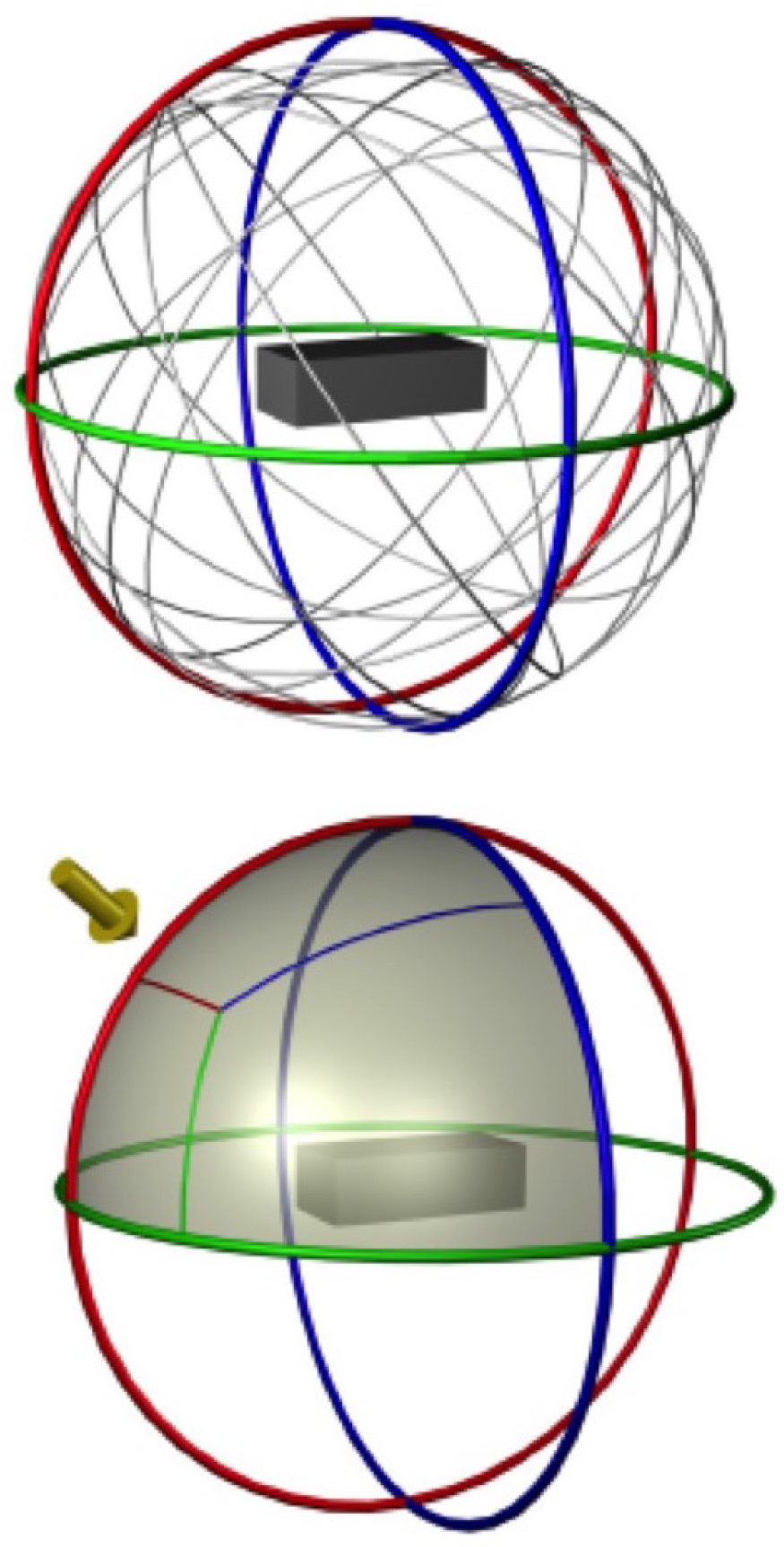
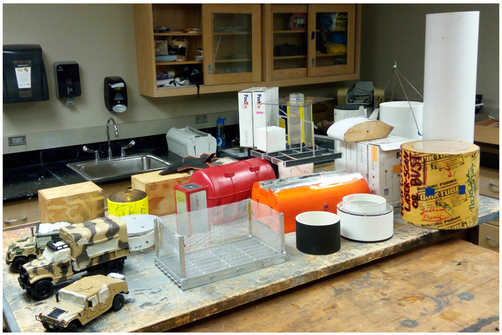
The case of the small-aspect-ratio circular cylinder, mentioned before, was studied extensively. The productivity and accuracy of this technique enabled systematic elimination of support interference, unsteady fluid mechanics, surface geometry accuracy, hysteresis and other misapprehensions. Features of the problem, including the variation with aspect ratio and the genesis of some of the aerodynamic loads, are explained in the work by Shukla et al. [114]. Over 60 shapes have been characterized to date in wind-tunnel measurements, each with 1-degree azimuthal resolution over the full 360-degree rotation about multiple axes depending on object symmetry or lack thereof. A new weighted interpolation scheme more accurately captures the aerodynamic loads at any arbitrary orientation. This approximates the ability to acquire data in rotation about any arbitrary axis as shown in Figure 4, and use them on-the-fly during dynamic simulation. This is discussed in the paper by Hiremath et al. [115]. A subset of these models is shown in Figure 5; they span a wide range of shapes and surface features. Both canonical shapes and practical configurations are included. Truncated Fourier series representations allow use of the aerodynamic load maps as analytical expressions for rapid dynamic simulation [110,116]. A dynamic simulation code was also developed [104,117], predicting full-scale dynamics and divergence on various objects [114,118] including military road vehicles [119].
Liberi et al. [120] used Ton’s nonlinear controls modeling [121] to show that safe flight near the divergence speed was possible, with random gust disturbances cancelled out using vehicle motions, albeit requiring high-bandwidth control power. This paper was a major advance, because it demonstrated that up to 10% uncertainty in aerodynamic loads had only small effects on the ultimate divergence speed. This negates much of the concern regarding accurate geometric modeling or surface imperfections. In turn, this led to the idea [122,123] that interpolated aerodynamic coefficients derived from knowledge bases on related canonical shapes could be used in a first-cut estimation of the divergence speed, pending wind-tunnel tests on the actual configuration.
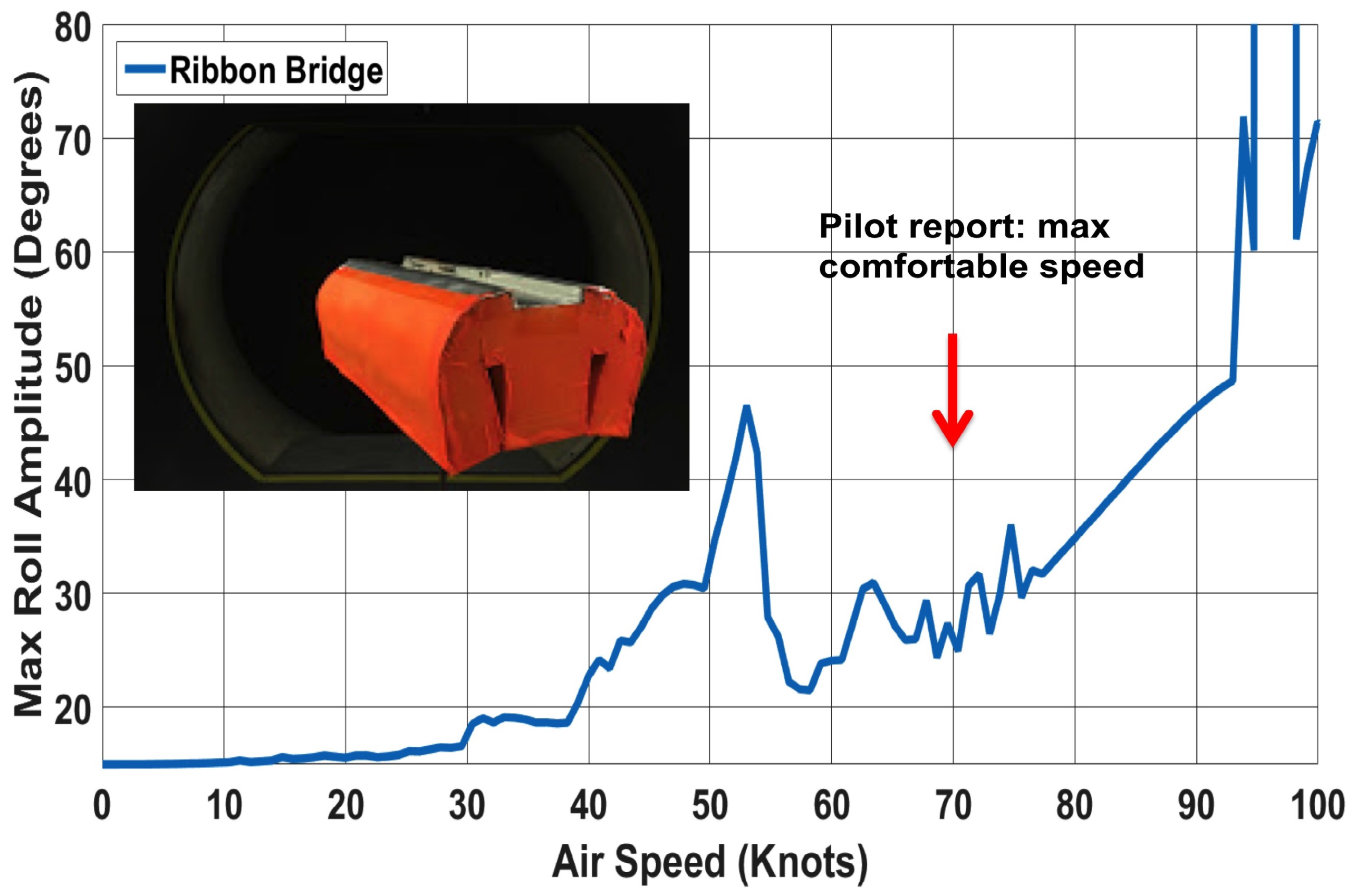
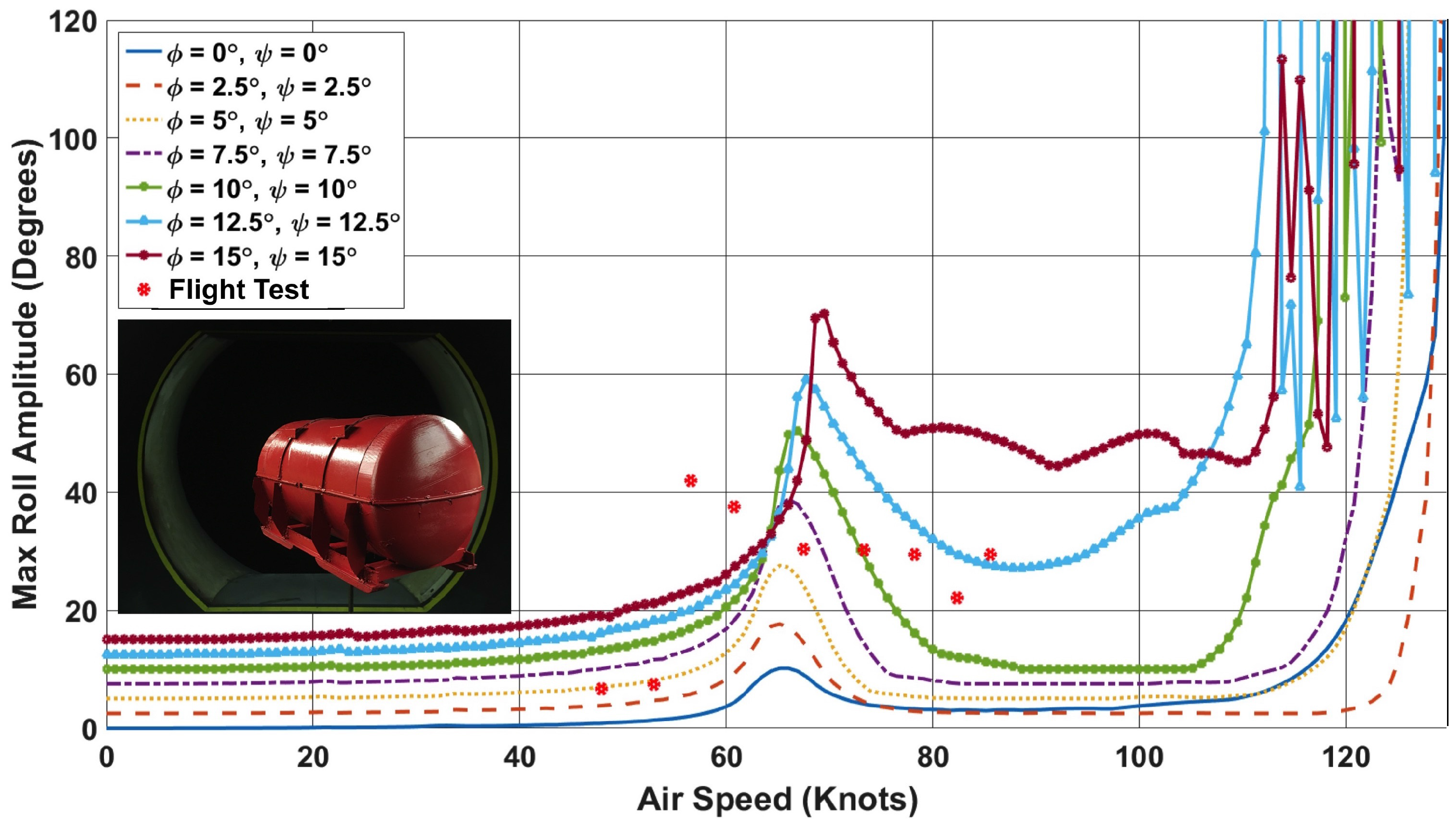
The success of the above approach has been demonstrated in comparisons with two flight test cases. These are the empty engine canister [102,103] and the ribbon bridge [101]. The engine canister is used to transport aircraft engines. The danger is when the empty canister is being returned as a slung load. The ribbon bridge is a component of a floating bridge, folded to fit a truck bed as well as be transported by helicopter slung load. Although the item is made of metal, it has sufficient buoyancy when laid in the water as parts of a two-lane bridge to support main battle tanks. Thus the effective density is very low, making the object a candidate for divergence. Full-scale flight test data are available [15]. Figure 6 and Figure 7 show the results. The sparse points are from the flight tests. The nearly continuous traces are from simulation results with several different initial perturbations of roll and yaw (we cannot know what those were in the flight test). Many, in fact all to date, simulations and wind-tunnel tests of slung-load dynamics show an intermediate speed range where there is amplification of roll oscillations which then decrease at higher speeds. This is called pseudo-divergence. The simulations shown for the engine canister and ribbon bridge both capture this phenomenon with surprisingly good agreement with the flight test data. A reviewer pointed out that this intermediate peak in Figure 7 is different by some 20 knots between the flight test and simulation. We cannot be certain why, given the limited information available about the flight test. It is possible that the moments of inertia of the empty canister are not accurately modeled. Also, the 12.5-degree and 15-degree initial conditions appear to lead to somewhat different responses than the lower initial amplitudes. The reasons for this are not clear. The amplification in this ’pseudo-divergence’ regime is sensitive to phase relationships between the different degrees of freedom, an aspect that is very difficult to capture precisely without live data. The more remarkable feature is the prediction of maximum pitch excursions. Both of the flight tests mentioned above were in fact terminated not by increasing roll oscillations, but by fear of tail rotor strike due to pitch excursions. The simulations do indeed show a sudden increase in the maximum amplitude of the pitch (trailing angle) near the speed where the crew terminated the flight tests. The reasons why these excursions occur are still being studied, per the authors.
Sharma [57,58] and Liberi [117] showed, using simple potential flow aerodynamics and mathematical models, how roll oscillations (pendulum motion) could amplify when coupled with yaw, due to wall effects. They then realized that amplification also occurred in the absence of walls, but much less so. They identified two mechanisms: the first is out-of-phase yaw, and the second is subharmonic yaw. The occurrence of sharp pitch oscillations is the third instability mechanism, whose precise genesis is still being sought.

7. Conclusions

This mini-review paper describes progress towards increasing the safety and speed of transporting bluff body objects as loads slung below aircraft. As of a decade ago, the problem looked intractable, the number of vehicle–load combinations far outstripping the ability to certify by flight tests. The anticipated alternative was to use high-resolution computation of fluid–structure coupled interactions, along with comprehensive flight dynamics prediction of flight vehicles. This approach is not only beyond reach of present-day computational resources, it also has stumbled on the realities of the state of the art in computational fluid dynamics. Given this realization, an alternative approach was needed, and is summarized in this review. Simplifying assumptions were made, and have enabled efficient simulation of actual flight test results. Specific conclusions are listed below:
  • For loads that are less than 30 percent of the gross weight of the rotorcraft, the feedback from the dynamics of the load to the rotorcraft is negligible. This is primarily because the main rotor has a very large moment of inertia, and this dominates the moment of inertia of the vehicle. Human-piloted rotorcraft have fairly low payload fractions. Most situations where divergence is a concern are cases where the slung load is light and has low inertia, so that the vehicle can fly fast. This means that where divergence is a concern with human-piloted rotorcraft, the load is significantly below 30 percent of gross weight.
  • The continuous rotation method has been used with high productivity to capture air loads, likely modes of instability, and divergence speeds of several shapes.
  • Aerodynamic coefficient maps have been obtained covering all relevant attitudes with excellent resolution and accuracy, on several classes of canonical and practical shapes. These enable rapid interpolation and synthesis of aerodynamic data for new shapes, for a first estimate of divergence speed, preceding actual wind-tunnel tests. Errors up to 10 percent error in aerodynamic loads have little effect on the divergence speed.
  • Froude-scaled model results from a small low-speed wind tunnel have correlated well with full-scale flight tests on cuboid (CONEX) containers.
  • Where the vehicle has a high payload fraction, amplification of roll oscillations occurring due to air disturbances occurring while flying near the divergence speed could be suppressed using fast vehicle maneuvers. Such maneuvers require high bandwidth and are hence better suited to uninhabited aerial vehicles (UAVs).
  • For the test case of a cylindrical engine canister, measurements of the object geometry were made from a technical description. An initial approximation of the geometry was made immediately, and the aerodynamic load map obtained by interpolating the existing Continuous Rotation (CR) knowledge base. Dynamic simulations were run using these data, and correctly captured the roll and pitch angle excursions that led to the flight test being ended.
  • For the test case of a ribbon bridge, wind-tunnel tests were conducted with a scale model, and the data were used in the simulation to successfully capture the roll and trail angle history. This was shown up to the speed where the actual flight test was stopped, and beyond.
  • The instabilities that amplify appear to stem from a very few classes of interactions.
  • With these demonstrations, it appears that the original problem of predicting the safe flight envelope of helicopters carrying arbitrary slung-load shapes is solved.

Acknowledgments

Much of the work at Georgia Tech was performed under the Vertical Lift Rotorcraft Center of Excellence project, Task 10A, sponsored by the Vertical Lift Consortium, from 2009 until December 2017. Tom Thompson is the technical point of contact. The assistance of several students in the Experimental Aerodynamics and Concepts Group at Georgia Tech is gratefully acknowledged.

Author Contributions

Narayanan Komerath led the project and wrote most of the paper. Nandeesh Hiremath and Dhwanil Shukla led the wind tunnel testing and analysis efforts at different phases of the work and reviewed several of the papers cited.

Conflicts of Interest

The authors declare no conflicts of interest.

References

  1. Anon. Multiservice Helicopter Sling Load: Single-Point Load Rigging Procedures; Technical Report; US Air Force: Washington, DC, USA, 2003.
  2. Anon. Multiservice Helicopter Sling Load: Basic Operations and Equipment. In Technical Memorandum TM 4-48.09 (FM 4-20.197) MCRP 4-11.3, Vol. INTTP 3-04.11 AFMAN 11-223 (I), Vol I COMDINST M13482.2B; United States Department of Defense, Headquarters, Departments of the Army, Navy, Marine Corps and Air Force: Washington, DC, USA, 2012. [Google Scholar]
  3. Dudley, M.; Greenhoe, G. Fifty years of helicopter firefighting. Fire Manag. Notes 1998, 58, 6–7. [Google Scholar]
  4. Matheson, N. Helicopter Slung Load Instabilities; Aerodynamics Note 364; Department of Defence, Defense Science and Technology Organisation, Aeronautical Research Laboratories: Melbourne, VIC, Australia, 1976. [Google Scholar]
  5. Starr, G.; Wood, J.; Lumia, R. Rapid Transport of Suspended Payloads. In Proceedings of the 2005 IEEE International Conference on Robotics and Automation, Roma, Italy, 10–14 April 2005; pp. 1394–1399. [Google Scholar]
  6. Grigel, J. Role of the Helitanker in Forest Fire Control; Information Report NOR-X-123; Enviroment Canada, Northern Forest Research Centre, Canadian Forestry SErvice: Edmonton, AB, Canada, 1974. [Google Scholar]
  7. De Voogt, A.J.; Uitdewilligen, S.; Eremenko, N. Safety in high-risk helicopter operations: The role of additional crew in accident prevention. Saf. Sci. 2009, 47, 717–721. [Google Scholar] [CrossRef]
  8. Stuckey, R. Dynamic Simulation of the CH-47D Helicopter and Externally Slung Boat. In Proceedings of the 3rd Australia Pacific Vertiflite Conference on Helicopter Technology, American Helicopter Society (AHS), Melbourne, Australia, 18–19 December 2000. [Google Scholar]
  9. Key, D.L. Airworthiness Qualification Criteria for Rotorcraft With External Sling Loads; Technical Report; NASA Ames Research Center: Moffett Field, CA, USA, 2002. [Google Scholar]
  10. Cicolani, L.S.; McCoy, A.H.; Sahai, R.; Tyson, P.H.; Tischler, M.B.; Rosen, A.; Tucker, G.E. Flight Test Identification and Simulation of a UH-60A Helicopter and Slung Load. J. Am. Helicopter Soc. 2001, 46, 140–160. [Google Scholar] [CrossRef]
  11. Cicolani, L.; Kanning, G. General Equilibrium Characteristics of a Dual-Lift Helicopter System; TP 2615; NASA: Washington, DC, USA, 1986. [Google Scholar]
  12. Cicolani, L.; Raz, R.; Rosen, A.; Gordon, R.; Cone, A.; Theron, J.; Lusardi, J.; Tischler, M.; Robinson, D. Flight Test, Simulation and Passive Stabilization of a Cargo Container Slung Load in Forward Flight. In Proceedings of the American Helicopter Society Annual Forum, Virginia Beach, VA, USA, 1–3 May 2007; Volume 63, p. 2177. [Google Scholar]
  13. Cicolani, L.; Lusardi, J.; Greaves, L.; Robinson, D.; Rosen, A.; Raz, R. Flight Test Results for the Motions and Aerodynamics of a Cargo Container and a Cylindrical Slung Load; Technical Paper TP 216380; NASA: Washington, DC, USA, 2010. [Google Scholar]
  14. Cicolani, L.; Kanning, G. A Comprehensive Estimate of the Static Aerodynamic Forces and Moments of the 8- by 8- by 20-Foot Cargo Container; Technical Report 89433; NASA: Washington, DC, USA, 1987. [Google Scholar]
  15. Thompson, T.; Thorpe, K. Final Report of Helicopter Sling-Load Working Working Group; Technical Report AMR-AE-06-01; Aviation and Missile Research, Development and Engineering Center: Huntsville, AL, USA, 2006. [Google Scholar]
  16. Cicolani, L.; Ivler, C.; Ott, C.; Raz, R.; Rosen, A. Rotational stabilization of cargo container slung loads. J. Am. Helicopter Soc. 2015, 60, 1–13. [Google Scholar] [CrossRef]
  17. Hoerner, S.F. Fluid-Dynamic Drag: Practical Information on Aerodynamic Drag and Hydrodynamic Resistance; Hoerner Fluid Dynamics: Midland Park, NJ, USA, 1965. [Google Scholar]
  18. Warner, E.P.; Norton, F.H. Wind Tunnel Balances; Report 72; National Advisory Committee for Aeronautics, Bureau of Construction and Repair (Navy): Washington, DC, USA, 1920. [Google Scholar]
  19. Zham, A. The Six-Component Wind Balance; Report 146; Aerodynamical Laboratory, U.S. Navy: Washington, DC, USA, 1922. [Google Scholar]
  20. Goldberg, C. Wind Tunnel Balance. U.S. Patent 2,380,516, 31 July 1945. [Google Scholar]
  21. Trimble, G.S. Six Component Balance for Wind Tunnels. U.S. Patent 2,768,526, 30 October 1956. [Google Scholar]
  22. Gieseler, L.P. Wind Tunnel Roll-Moment Balance. U.S. Patent 2,865,200, 23 December 1958. [Google Scholar]
  23. Ormond, A.N. Force Measuring Instrument. U.S. Patent 2,918,816, 29 December 1959. [Google Scholar]
  24. Kutsay, A.U. Strain Detecting Load Cell. U.S. Patent 3,695,096, 3 October 1959. [Google Scholar]
  25. Zipin, R.B. Multi-Axis Load Cell. U.S. Patent 3,939,704, 24 January 1976. [Google Scholar]
  26. Wasko, B. Precision Balance. U.S. Patent 3,955,638, 11 May 1976. [Google Scholar]
  27. Dubois, M. Six-Component Strain-Gage Balances for Large Wind Tunnels. Exp. Mech. 1981, 21, 401–407. [Google Scholar] [CrossRef]
  28. Meyer, R.A.; Olson, D.J. Six Axis Load Cell. U.S. Patent 5,315,882, 31 May 1994. [Google Scholar]
  29. Almeida, R.A.; Vaz, D.C.; Urgueira, A.P.; Borges, A.J. Using ring strain sensors to measure dynamic forces in wind-tunnel testing. Sens. Actuators A Phys. 2012, 185, 44–52. [Google Scholar] [CrossRef]
  30. Green, J.; Quest, J. A short history of the European Transonic Wind Tunnel ETW. Prog. Aerosp. Sci. 2011, 47, 319–368. [Google Scholar] [CrossRef]
  31. Habéis, T.A. The 7 by 10 Foot Wind Tunnel of the National Advisory Committee for Aeronautics; Report; NASA: Washington, DC, USA, 1933. [Google Scholar]
  32. Pope, A.; Harper, J.J. Low Speed Wind Tunnel Testing; John Wiley & Sons Inc.: Hoboken, NJ, USA, 1966. [Google Scholar]
  33. Horanoff, E.V. Wind Tunnel Balance. U.S. Patent 3,447,369, 3 June 1969. [Google Scholar]
  34. Pinier, J.; Hanke, J.L.; Tomek, W.G. Ares I Aerodynamic Testing at the Boeing Polysonic Wind Tunnel. J. Spacecr. Rocket. 2012, 49, 853–863. [Google Scholar] [CrossRef]
  35. Mehta, R.D. Aerodynamics of sports balls. Ann. Rev. Fluid Mech. 1985, 17, 151–189. [Google Scholar] [CrossRef]
  36. Jones, T.W.; Lunsford, C.B.; Graves, S.S. Design and development of a real-time model attitude measurement system for hypersonic facilities. In Proceedings of the 43rd AIAA Aerospace Sciences Meeting, Reno, NV, USA, 10–13 January 2005. [Google Scholar]
  37. DeLoach, R. The modern design of experiments: A technical and marketing framework. In Proceedings of the 21st AIAA Advanced Measurement Technology and Ground Testing Conference, Denver, CO, USA, 19–22 June 2000; Volume 2691. [Google Scholar]
  38. Raz, R.; Rosen, A.; Carmeli, A.; Lusardi, J.; Cicolani, L.; Robinson, D. Wind Tunnel and Flight Evaluation of Passive Stabilization of a Cargo Container Slung Load. J. Am. Helicopter Soc. 2010, 55, 032001. [Google Scholar] [CrossRef]
  39. Rosen, A.; Cecutta, S.; Yaffe, R. Wind Tunnel Tests of Cube and CONEX Models. Technion Inst. Technol. Dep. Aerospace Eng. Haifa Israel TAE 1999. [Google Scholar]
  40. Gabel, R.; Wilson, G.J. Test approaches to external sling load instabilities. J. Am. Helicopter Soc. 1968, 13, 44–55. [Google Scholar]
  41. Nakamura, Y. Bluff-Body Aerodynamics and Turbulence. J. Wind Eng. Ind. Aerodyn. 1993, 49, 65–78. [Google Scholar] [CrossRef]
  42. Zdravkovich, M.; Brand, V.; Mathew, G.; Weston, A. Flow past short circular cylinders with two free ends. J. Fluid Mech. 1989, 203, 557–575. [Google Scholar] [CrossRef]
  43. Zdravkovich, M.; Flaherty, A.; Pahle, M.; Skelhorne, I. Some aerodynamic aspects of coin-like cylinders. J. Fluid Mech. 1998, 360, 73–84. [Google Scholar] [CrossRef]
  44. Greenwell, D. Modelling of static aerodynamics of helicopter underslung loads. Aeronaut. J. 2011, 115, 201–219. [Google Scholar] [CrossRef]
  45. Koenig, K.; Roshko, A. An experimental study of geometrical effects on the drag and flow field of two bluff bodies separated by a gap. J. Fluid Mech. 1985, 156, 167. [Google Scholar] [CrossRef]
  46. Lee, B. Some Observations of the Effect of Aspect Ratio on the Influence of Turbulence on the Drag of Rectangular Cylinders. J. Wind Eng. Ind. Aerodyn. 1990, 33, 107–111. [Google Scholar] [CrossRef]
  47. Windsor, R. Wind Tunnel Tests of Two Models of Rectangular Containers; Report 573; Glenn Martin Wind Tunnel, University of Maryland: College Park, MD, USA, 1970. [Google Scholar]
  48. Roshko, A. Experiments on the flow past a circular cylinder at very high Reynolds number. J. Fluid Mech 1961, 10, 345–356. [Google Scholar] [CrossRef]
  49. Matsumoto, M. Vortex Shedding of Bluff Bodies: A Review. J. Fluids Struct. 1999, 13, 791–811. [Google Scholar] [CrossRef]
  50. Komatsu, S.; Kobayashi, H. Vortex-Induced Oscillation of Bluff Cylinders. J. Wind Eng. Ind. Aerodyn. 1980, 6, 335–362. [Google Scholar] [CrossRef]
  51. King, R. A Review of Vortex Shedding Research and Its Application. Ocean Eng. 1977, 4, 141–171. [Google Scholar] [CrossRef]
  52. Barnes, F.H.; Grant, I. Vortex Shedding in Unsteady Flow. J. Wind Eng. Ind. Aerodyn. 1983, 11, 335–344. [Google Scholar] [CrossRef]
  53. Bearman, P.; Morel, T. Effect of free stream turbulence on the flow around bluff bodies. Prog. Aerosp. Sci. 1983, 20, 97–123. [Google Scholar] [CrossRef]
  54. Bentley, J.; Mudd, J. Vortex Shedding Mechanisms in Single and Dual Bluff Bodies. Flow Meas. Instrum. 2003, 14, 23–31. [Google Scholar] [CrossRef]
  55. Wei, C.; Chang, J. Wake and Base-Bleed Flow Downstream of Bluff Bodies with Different Geometry. Exp. Therm. Fluid Sci. 2002, 26, 39–52. [Google Scholar] [CrossRef]
  56. Bearman, P.; Tombazis, N. The Effects of Three-Dimensional Imposed Disturbances on Bluff Body Near Wake Flows. J. Wind Eng. Ind. Aerodyn. 1993, 49, 339–350. [Google Scholar] [CrossRef]
  57. Sharma, S.; Komerath, N.; Raghav, V. Aerodynamic Instability Modes for a Load Slung From a Helicopter. In Proceedings of the ASME 2012 International Mechanical Engineering Congress and Exposition, American Society of Mechanical Engineers, Houston, TX, USA, 9–15 November 2012; pp. 481–489. [Google Scholar]
  58. Sharma, S.; Raghav, V.; Komerath, N. Efficient Modeling of Dynamic Blockage Effects for Unsteady Wind Tunnel Testing. In Proceedings of the 69th American Helicopter Society Annual Forum, Phoenix, AZ, USA, 21–23 May 2013. [Google Scholar]
  59. Swanson, W. The Magnus effect: A summary of investigations to date. J. Basic Eng. 1961, 83, 461–470. [Google Scholar] [CrossRef]
  60. Szepessy, S.; Bearman, P. Aspect ratio and end plate effects on vortex shedding from a circular cylinder. J. Fluid Mech. 1992, 234, 191–217. [Google Scholar] [CrossRef]
  61. Norberg, C. An experimental investigation of the flow around a circular cylinder: Influence of aspect ratio. J. Fluid Mech. 1994, 258, 287–316. [Google Scholar] [CrossRef]
  62. Sheldon, D.; Pryor, J. Study in Depth of a Single Point and Two Point Lateral and Tandem Suspension of Rectangular Box Loads; Technical Note AM 38; The Royal Military College of Science: Shrivenham, UK, 1973. [Google Scholar]
  63. Nagabhushan, B.L. Systematic Investigation of Models of Helicopter With a Slung Load. Ph.D. Thesis, Virginia Polytechnic Institute and State University, Blacksburg, VA, USA, 1977. [Google Scholar]
  64. Micale, E.C.; Poli, C. Dynamics of Sling Bodies using a Rotating Wheel for Stability. J. Aircr. 1973, 10, 80–86. [Google Scholar] [CrossRef]
  65. Watkins, T.; Sinacori, J.; Kesler, D. Stabilization of Externally Slung Helicopter Loads; Technical Report TR-74-42; USAAMRDL: Moffett Field, CA, USA, 1974. [Google Scholar]
  66. Reddy, K.; Truong, T.; Stuckey, R.; Bourne, K. Dynamic simulation of a helicopter carrying a slung load. In Proceedings of the International Congress on Modeling and Simulation, University of Canterbury, Christchurch, New Zealand, 10–13 December 2007; pp. 2740–2746. [Google Scholar]
  67. Feaster, L.; Poli, C.; Kirchhoff, R. Dynamics of a Slung Load. J. Aircr. 1977, 14, 115–121. [Google Scholar] [CrossRef]
  68. Tyson, P.; Cicolani, L.; Tischler, M.; Rosen, A.; Levine, D.; Dearing, M. Simulation Prediction and Flight Validation of the UH-60A Black Hawk Slung Load Characteristics. In Proceedings of the American Helicopter Society Annual Forum, Montreal, QC, Canada, 25–27 May 1999; Volume 55, pp. 2075–2100. [Google Scholar]
  69. Bernard, M.; Kondak, K. Generic slung load transportation system using small size helicopters. In Proceedings of the IEEE International Conference on Robotics and Automation, Kobe, Japan, 12–17 May 2009; pp. 3258–3264. [Google Scholar]
  70. Bisgaard, M.; Bendtsen, J.D.; Cour-Harbo, L.; Anders. Modelling of Generic Slung Load System. In Proceedings of the AIAA Modeling and Simulation Technologies Conference and Exhibit, Keystone, CO, USA, 21–24 August 2006. [Google Scholar]
  71. Bisgaard, M.; la Cour-Harbo, A.; Bendtsen, J.D. Adaptive control system for autonomous helicopter slung load operations. Control Eng. Pract. 2010, 18, 800–811. [Google Scholar] [CrossRef]
  72. Cicolani, L.S.; Cone, A.; Theron, J.N.; Robinson, D.; Lusardi, J.; Tischler, M.B.; Rosen, A.; Raz, R. Flight test and simulation of a cargo container slung load in forward flight. J. Am. Helicopter Soc. 2009, 54, 32006. [Google Scholar] [CrossRef]
  73. Fusato, D.; Guglieri, G.; Celi, R. Flight Dynamics of an Articulated Rotor Helicopter with an External Slung Load. In Proceedings of the 55th American Helicopter Society Annual Forum, Montreal, QC, Canada, 25–27 May 1999. [Google Scholar]
  74. Oktay, T.; Sultan, C. Modeling and control of a helicopter slung-load system. Aerosp. Sci. Technol. 2013, 29, 206–222. [Google Scholar] [CrossRef]
  75. Palunko, I.; Fierro, R.; Cruz, P. Trajectory generation for swing-free maneuvers of a quadrotor with suspended payload: A dynamic programming approach. In Proceedings of the 2012 IEEE International Conference on Robotics and Automation (ICRA), Saint Paul, MN, USA, 14–18 May 2012; pp. 2691–2697. [Google Scholar]
  76. Stuckey, R.A. Mathematical Modelling of Helicopter Slung-Load Systems; Technical Report DSTO-TR-1257; Australian Government Department of Defence, Defence Science and Technology Organisation: Melbourne, VIC, Australia, 2001.
  77. Menter, F. Two-Equation Eddy-Viscosity Turbulence Models for Engineering Applications. AIAA J. 1994, 32, 1598–1605. [Google Scholar] [CrossRef]
  78. Bonhaus, D. An Upwind Multigrid Method For Solving Viscous Flows On Unstructured Triangular Meshes. Master’s Thesis, George Washington University, Washington, DC, USA, 1993. [Google Scholar]
  79. Theron, J.; Gordon, R.; Rosen, A.; Cicolani, L.; Duque, E.; Halsey, R. Simulation of Helicopter Slung Load Aerodynamics: Wind tunnel validation of two computational fluid dynamics codes. In Proceedings of the 36th AIAA Fluid Dynamics Conference, San Francisco, CA, USA, 5–8 June 2006. [Google Scholar]
  80. Mantri, R.; Raghav, V.; Komerath, N.; Smith, M.J. Stability Prediction of Sling Load Dynamics Using Wind Tunnel Models. In Proceedings of the 67th American Helicopter Society Annual Forum, Virginia Beach, VA, USA, 3–5 May 2011. [Google Scholar]
  81. Prosser, D.; Smith, M. Navier-Stokes-Based Dynamic Simulations of Sling Loads. In Proceedings of the 54th AIAA Structures, Structural Dynamics, and Materials Conference, Boston, MA, USA, 8–11 April 2013. [Google Scholar]
  82. Raghav, V.; Mantri, R.; Komerath, N.; Smith, M. Study of Factors Driving Pitch, Roll and Yaw Coupling in Bluff Body Aerodynamics. In Proceedings of the AIAA Applied Aerodynamics Conference, Honolulu, HI, USA, 27–30 June 2011. [Google Scholar]
  83. Beard, R. Quadrotor Dynamics and Control Rev 0.1; Technical Report; Brigham Young University: Provo, UT, USA, 2008. [Google Scholar]
  84. De Crousaz, C.; Farshidian, F.; Neunert, M.; Buchli, J. Unified motion control for dynamic quadrotor maneuvers demonstrated on slung load and rotor failure tasks. In Proceedings of the 2015 IEEE International Conference on Robotics and Automation (ICRA), Seattle, WA, USA, 26–30 May 2015; pp. 2223–2229. [Google Scholar]
  85. Ivler, C. Design and Flight Test of a Cable Angle Feedback Control System for Improving Helicopter Slung Load Operations at Low Speed; Technical Report; AMRDEC, Aeroflightdynamics Directorate: Moffett Field, CA, USA, 2014. [Google Scholar]
  86. Lee, S.J.; Kim, H.J. Autonomous swing-angle estimation for stable slung-load flight of multi-rotor UAVs. In Proceedings of the 2017 IEEE International Conference on Robotics and Automation (ICRA), Singapore, 29 May–3 June 2017; pp. 4576–4581. [Google Scholar]
  87. Krishnamurthi, J.; Horn, J.F. Helicopter Slung Load Control Using Lagged Cable Angle Feedback. J. Am. Helicopter Soc. 2015, 60, 1–12. [Google Scholar] [CrossRef]
  88. Johnson, N.A. Control of a Folding Quadrotor with a Slung Load Using Input Shaping. Ph.D. Thesis, Georgia Institute of Technology, Atlanta, GA, USA, 2017. [Google Scholar]
  89. Kui, Y.; Feng, G.; Liying, Y.; Yuqing, H.; Jianda, H. Sliding mode control for a quadrotor slung load system. In Proceedings of the 2017 36th Chinese Control Conference (CCC), Dalian, China, 26–28 July 2017; pp. 3697–3703. [Google Scholar]
  90. Mo, R.; Geng, Q.; Lu, X. Study on control method of a rotor UAV transportation with slung-load. In Proceedings of the 2016 35th Chinese Control Conference (CCC), Chengdu, China, 27–29 July 2016; pp. 3274–3279. [Google Scholar]
  91. Nonnenmacher, D.; Kim, H.; Götz, J.; Weber, P.; von Hinüber, E.; Knedlik, S. System architecture of HALAS—A helicopter slung load stabilisation and positioning system. CEAS Aeronaut. J. 2014, 5, 127–143. [Google Scholar] [CrossRef]
  92. Pereira, P.O.; Herzog, M.; Dimarogonas, D.V. Slung load transportation with a single aerial vehicle and disturbance removal. In Proceedings of the 2016 24th Mediterranean Conference on Control and Automation (MED), Athens, Greece, 21–24 June 2016; pp. 671–676. [Google Scholar]
  93. Pollini, L.; Metrangolo, A. Simulation and Robust Backstepping Control of a Quadrotor Aircraft. In Proceedings of the Guidance, Navigation, and Control and Co-located Conferences, American Institute of Aeronautics and Astronautics, Honolulu, HI, USA, 18–21 August 2008. [Google Scholar]
  94. Raptis, I.; Valavanis, K.; Moreno, W. A Novel Nonlinear Backstepping Controller Design for Helicopters Using the Rotation Matrix. IEEE Trans. Control Syst. Technol. 2011, 19, 465–473. [Google Scholar] [CrossRef]
  95. Tartaglione, G.; D’Amato, E.; Ariola, M.; Rossi, P.S.; Johansen, T.A. Model predictive control for a multi-body slung-load system. Robot. Auton. Syst. 2017, 92, 1–11. [Google Scholar] [CrossRef]
  96. Vargas, A.; Ireland, M.L.; Anderson, D. Swing-Free Manoeuvre Controller for Rotorcraft Unmanned Aerial Vehicle Slung-Load System Using Echo State Networks. Int. J. Unmanned Syst. Eng. 2015, 3, 26. [Google Scholar] [CrossRef]
  97. Vargas, A.; Anderson, D. Computer vision technique to estimate the slung load dynamics when coupled to a Multirotor Unmanned Aerial Vehicle. Rev. Int. Investig. e Innov. Tecnol. (RIIIT) 2017, 1–10. Available online: https://www.researchgate.net/publication/318458252_Computer_vision_technique_to_estimate_the_slung_load_dynamics_when_coupled_to_a_Multirotor_Unmanned_Aerial_Vehicle (accessed on 25 February 2018).
  98. Zuo, Z.; Zhu, M.; Zheng, Z. Trajectory Tracking Control of a Quadrotor Unmanned Mini-Helicopter. In Proceedings of the Aerospace Sciences Meetings, American Institute of Aeronautics and Astronautics, Orlando, FL, USA, 4–7 January 2010. [Google Scholar]
  99. Gibson, J. Blackhawk helicopter with sling–loaded Humvee. US Army Photo by Staff Sgt. Joel Gibson; 13th SC(E) Public Affairs. Courtesy US Army, 2014. [Google Scholar]
  100. Hiremath, N.; Shukla, D.; Hale, E.; Sparacello, T.; Komerath, N. Slung Load Amplification Detector. In Proceedings of the ASME 2017 International Mechanical Engineering Conference and Exposition IMECE2017, Tampa, FL, USA, 3–9 November 2017. Number IMECE2017-70252. [Google Scholar]
  101. Motahari, N.; Hiremath, N.; Komerath, N. Aerodynamic Load Maps of Bluff-Body Combinations in Incompressible Flow. In Proceedings of the ASME 2016 Fluids Engineering Division Summer Meeting (ASME), Washington, DC, USA, 10–14 July 2016. Number FEDSM2016-7683. [Google Scholar]
  102. Motahari, N.; Hiremath, N.; Komerath, N. Towards Generalized Certification of Slung Load Flight Envelopes. In Proceedings of the 72nd Forum of AHS International American Helicopter Society, West Palm Beach, FL, USA, 17–19 May 2016. [Google Scholar]
  103. Motahari, N.; Hiremath, N.; Komerath, N. Generalized Approach for Slung-Load Aerodynamics. In Proceedings of the 72nd Forum of AHS International American Helicopter Society, West Palm Beach, FL, USA, 17–19 May 2016. [Google Scholar]
  104. Motahari, N.; D’Turbeville, F.; Hiremath, N.; Komerath, N. Airload Maps of Vehicle Shapes at Arbitrary Attitude. In Proceedings of the SAE Aerotech Conference, Seattle, WA, USA, 22–24 September 2015. Paper Number 2015-01-15ATC-0198. [Google Scholar]
  105. Komerath, N.; Raghav, V.; Hiremath, N. Aerodynamics of Arbitrary Shapes. In Aerodynamic Loads on Arbitrary Shapes; SCV Inc.: Alpharetta, GA, USA, 2016. [Google Scholar]
  106. Komerath, N.; Hiremath, N. Closed Circular Cylinders in Yaw; Number Book 2 in Aerodynamics of Arbitrary Shapes; SCV Inc.: Alpharetta, GA, USA, 2016. [Google Scholar]
  107. Forbes, A.; Raghav, V.; Mayo, M.; Komerath, N. Rotation Effects on Hub Drag. In Proceedings of the ASME 2013 International Mechanical Engineering Congress & Exposition, San Diego, CA, USA, 15–21 November 2013. [Google Scholar]
  108. Mastinu, G.; Gobbi, M.; Previati, G. A new six-axis load cell. Part I: Design. Exp. Mech. 2011, 51, 373–388. [Google Scholar] [CrossRef]
  109. Forbes, A.; Raghav, V.; Komerath, N. Continuous Rotation Technique to Measure Aerodynamic Loads ona Bluff Body; Data Report ADLP-2013090501; Experimental Aerodynamics and Concepts Group, School of AE, Georgia Institute of Technology: Atlanta, GA, USA, 2013. [Google Scholar]
  110. Forbes, A.; Pirau, S.; Liberi, B.; Raghav, V.; Komerath, N. Testing-Based Approach to Determining the Divergence Speed of Slung Loads. In Proceedings of the 70th American Helicopter Society Forum, Montreal, QC, Canada, 20–22 May 2014. [Google Scholar]
  111. Pirau, S.; Forbes, A.; Liberi, B.; Raghav, V.; Komerath, N. Quasi-Steady Air Loads Report: CUBOID; Data Report ADLP2015022401; Experimental Aerodynamics and Concepts Group, School of AE, Georgia Institute of Technology: Atlanta, GA, USA, 2015. [Google Scholar]
  112. Pirau, S.; Forbes, A.; Liberi, B.; Raghav, V.; Komerath, N. Quasi-Steady Air Loads Report: Flat Plate with Central Load; Data Report ADLP2015022402; Experimental Aerodynamics and Concepts Group, School of AE, Georgia Institute of Technology: Atlanta, GA, USA, 2015. [Google Scholar]
  113. Pirau, S.; Forbes, A.; Liberi, B.; Raghav, V.; Komerath, N. Quasi-Steady Air Loads Report: Porous Box; Data Report ADLP2015022403; Experimental Aerodynamics and Concepts Group, School of AE, Georgia Institute of Technology: Atlanta, GA, USA, 2015. [Google Scholar]
  114. Shukla, D.; Hiremath, N.; Motahari, N.; Komerath, N. Genesis of the Airload Variations on Cylinders of Small Aspect Ratios. In Proceedings of the ASME 2015 International Mechanical Engineering Congress and Exposition, American Society of Mechanical Engineers, Houston, TX, USA, 13–19 November 2015. [Google Scholar]
  115. Hiremath, N.; Shukla, D.; Robinson, J.; Jha, A.; Palaniappan, A.; Komerath, N. Aerodynamic Loads on Arbitrary Configurations: Measurements, Computations and Geometric Modeling. In Proceedings of the SAE AeroTech Conference on Society of Automotive Engineers, Ft. Worth, TX, USA, 26–28 September 2017. Paper Number 2017-01-02162. [Google Scholar]
  116. Pirau, S.; Raghav, V.; Forbes, A.; Liberi, B.; Komerath, N. Efficient Airload Determination For Bluff Body Aeromechanics. In Proceedings of the ASME 2014 International Mechanical Engineering Congress & Exposition, Montreal, QC, Canada, 14–20 November 2014. [Google Scholar]
  117. Liberi, B.; Pirau, S.; Raghav, V.; Komerath, N. Determination Of Slung Load Divergence Speed Using Airloa Measurement And Simulation. In Proceedings of the ASME 2014 International Mechanical Engineering Congress & Exposition, Montreal, QC, Canada, 14–20 November 2014. Number IMECE2014-38260 in ASME Paper. [Google Scholar]
  118. Liberi, B.; Ton, C.; Komerath, N. Divergence Speed Prediction For Practical Slung Load Shapes. In Proceedings of the ASME-JSME-KSME Joint Fluids Engineering Conference, Seoul, Korea, 26–31 July 2015. Number AJK2015-27543 in Paper. [Google Scholar]
  119. Liberi, B.; Kijjakarn, P.; Komerath, N. Slung Load Divergence Speed Predictions for Vehicle Shapes. In Proceedings of the SAE AeroTech Conference, Seattle, WA, USA, 22–24 September 2015. [Google Scholar]
  120. Liberi, B.; Pirau, S.; Komerath, N.; Ton, C. Effects of Uncertainty on Slung Load Divergence Speed Determination. In Proceedings of the 71st American Helicopter Society Forum, Virginia Beach, VA, USA, 5–7 May 2015. [Google Scholar]
  121. Ton, C.; Mackunis, W. Robust Attitude Tracking Control of a Quadrotor Helicopter in the Presence of Uncertainty. In Proceedings of the IEEE Conference on Decision and Control (CDC), Maui, HI, USA, 10–13 December 2012; pp. 937–942. [Google Scholar]
  122. Pirau, S.; Liberi, B.; Barbely, N.; Komerath, N. Generalized Prediction of Bluff-Body Aerodynamic Load Maps. In Proceedings of the ASME-JSME-KSME Joint Fluids Engineering Conference AJK2015-FED, Number 15542 in AJK2015, Seoul, Korea, 26–31 July 2015. [Google Scholar]
  123. Motahari, N.; Hiremath, N.; Shukla, D.; Liberi, B.; Thorell, N.; Komerath, N. Generalized Airloads Prediction for Bluff Bodies Transported as Slung Loads. In Proceedings of the ASME 2015 International Mechanical Engineering Congress and Exposition, American Society of Mechanical Engineers, Houston, TX, USA, 13–19 November 2015. [Google Scholar]
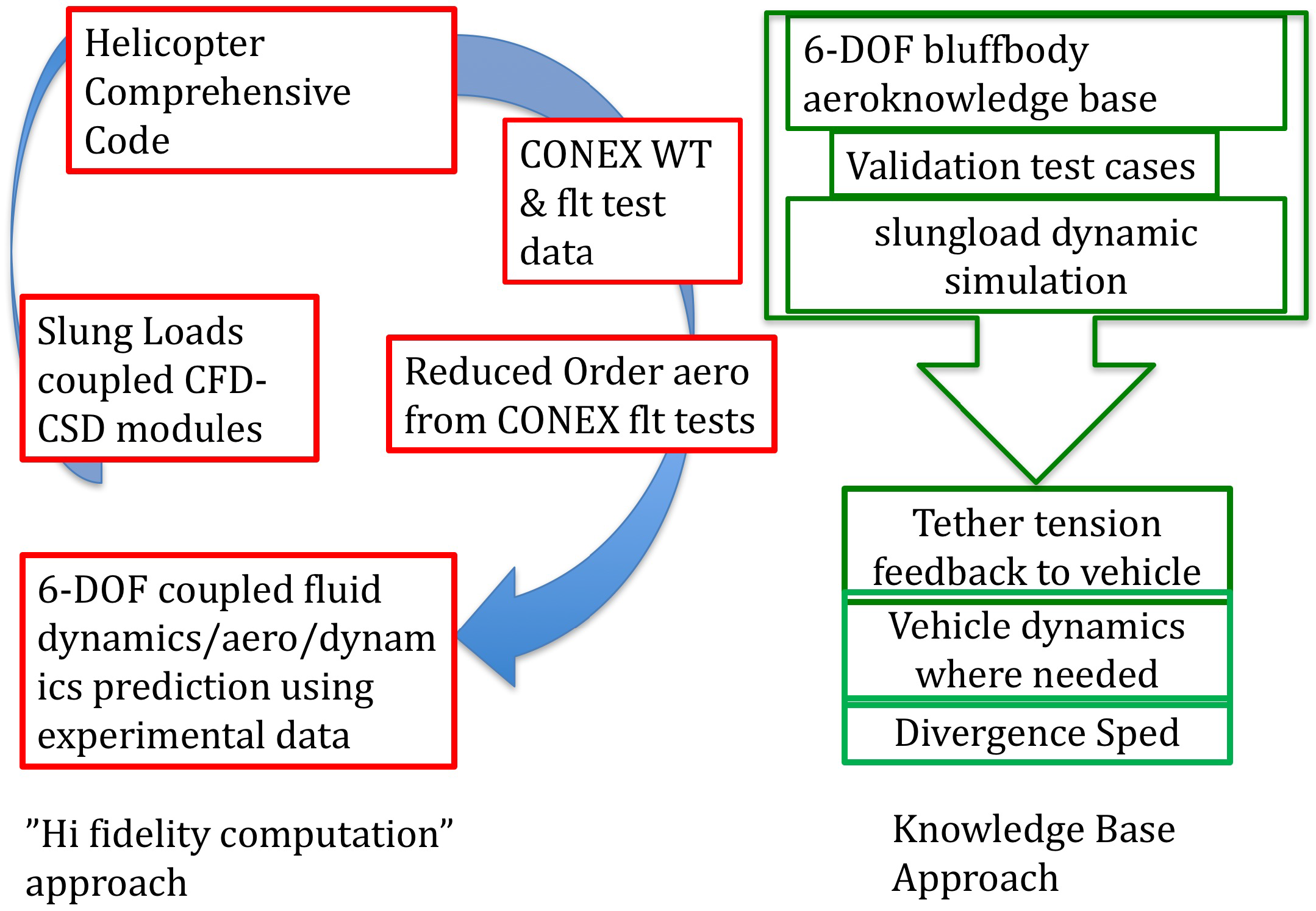
Figure 1. Blackhawk helicopter maneuvering with a military vehicle slung underneath. From [99], Courtesy US Army. Work of the US Government.
Aerospace 05 00024 g001
Figure 2. Comparison of approaches to certify the maximum safe speed of a vehicle with slung load. From [100] by permission of authors.
Aerospace 05 00024 g002
Figure 3. Example of a continuously rotating load measurement setup. A slender cylindrical rod is used as support, mounted on stepper motor that is fixed to a load cell.
Aerospace 05 00024 g003
Figure 4. The full aerodynamic load map for a given shape requires finely-resolved azimuthal variations about any arbitrary axis of rotation. From [115]. By permission of authors.
Aerospace 05 00024 g004
Figure 5. Some of the models on which aerodynamic load maps have been generated in the wind tunnel using the continuous rotation technique. From [100] by permission of authors.
Aerospace 05 00024 g005
Figure 6. Maximum roll amplitude versus flight speed for a ribbon bridge model, predicted by dynamic simulation with model-scale wind-tunnel aerodynamic data, compared to flight test points. From [100] by permission of authors.
Aerospace 05 00024 g006
Figure 7. Maximum roll amplitude versus flight speed for an empty engine container, predicted by dynamic simulation with model-scale wind-tunnel aerodynamic data, compared to flight test points. From [100] by permission of authors.
Aerospace 05 00024 g007