Article

Simulation and Experimental Evaluation of a Flexible Time Triggered Ethernet Architecture Applied in Satellite Nano/Micro Launchers

by
Vincenzo Eramo
1,*,
Francesco G. Lavacca
1,
Francesco Valente
1,
Andrea Pisculli
2 and
Stefano Caporossi
2
1
DIET, Sapienza University of Rome, 00184 Rome, Italy
2
SPACELAB, Via degli Esplosivi 1, 00134 Colleferro, Italy
*
Author to whom correspondence should be addressed.
Aerospace 2018, 5(3), 84; https://doi.org/10.3390/aerospace5030084
Submission received: 13 July 2018 / Revised: 4 August 2018 / Accepted: 7 August 2018 / Published: 9 August 2018
(This article belongs to the Special Issue Verification Approaches for Nano- and Micro-Satellites)

Abstract

:
The success of small satellites has lead to the study of new technologies for the realization of Nano and Micro Launch Vehicle (NMLV) in order to make competitive launch costs. The paper has the objective to define and experimentally investigate the performance of a communication system for NMLV interconnecting the End Systems as On-Board Computer (OBC), telemetry apparatus, Navigation Unit...we propose a low cost Ethernet-based solution able to provide the devices with high interconnection bandwidth. To guarantee hard delays to the Guide, Navigation and Control applications we propose some architectural changes of the traditional Ethernet network with the introduction of a layer implemented in the End Systems and allow for the lack of any contention on the network links. We show how the proposed solution has comparable performance to the one of TTEthernet standard that is a very expensive solution. An experimental test-bed equipped with Ethernet switches and Hercules boards by Texas Instruments is also provided to prove the feasibility of the proposed solution.

1. Introduction

The miniaturization of electronics, together with reliability and performance increase as well as reduction of cost, have allowed the use of Commercials-Off-The-Shelf (COTS) hardware/software in the space industry, fostering the use of a small satellite. An analysis of current and future launch vehicles reveals that we are currently in a phase of transition, where old launch vehicles get retired and new ones enter the market. However, the satellite launch vehicle business has been established to carry payloads of thousands of kilos into low Earth orbit and has not adjusted itself to the market of small satellites. As a result, there is only one launch vehicle for dedicated small satellite launches commercially available, but it carries a high price tag. In fact, the only commercially available Micro Launch Vehicle appropriate for dedicated Mini and Micro satellites is Pegasus with a payload capacity of about 250 kg. It carries a price tag of USD 56.3 million [1].
Several small low cost launch vehicles are under development. Since these small launch vehicles have similar complexity as huge launch vehicles, high development costs are intrinsic, leading to a high specific price (USD/kg payload) [1].
This paper is focused on the communication system of a launch vehicle interconnecting On-Board Computer (OBC), Telemetry apparatus, Navigation Unit. To get competitive launch prices, solutions have to be identified at lower costs than the ones for traditional launchers. The objective of the paper is to propose and experimentally investigate a low cost communication system for a Nano and Micro Launch Vehicle (NMLV) based on Ethernet technology. Actually the network used in small launchers is based on a 1553B [2] bus technology that has shown many limits in recent years. In Vettore Europeo di Generazione Avanzata (VEGA), small launcher jointly designed by Italian Space Agency and European Space Agency [3], the 1 Mb/s bandwidth of the 1553B bus is now saturated and this prevents it from transporting additional telemetry messages.
One of the main factors of attractions to Ethernet is due to its high bandwidth, much higher than in other communication networks. Another one is that the prices of Commercial-Of-The-Shelf (COTS) standard Ethernet components are relatively low [4,5,6]. Since standard Ethernet was not originally designed to be capable of providing temporal guarantees for real-time communication, there have been many protocol designs adapting standard Ethernet to be capable of providing such temporal guarantees. Some examples are: EtherCAT, Ethernet/IP, PROFINET [7], Avionic Full Duplex Ethernet (AFDX) [8] and TTEthernet [9,10,11,12]. AFDX and TTEthernet are considered as mature solutions but their high cost suggests to study alternative solutions. The proposed communication system will be based on the following architectural choices:
  • use of Common-Off-The-Shelf (COTS) Ethernet technology as much as possible with the addition of the minimum number of functional components for the support of real-time traffic;
  • use of traditional Ethernet switches, full duplex transmission and simple network topology in order to reduce the number of both nodes and ports;
  • implementation of a real-time layer bypassing the Transmission Control Protocol/User Datagram Protocol/Internet Protocol (TCP/UDP/IP) stack to avoid potential delays introduced by this protocols;
  • definition of a layer for the scheduling of messages so as to guarantee the Quality of Service (QoS) requested by the Guide, Navigation and Control and telemetry applications.
We consider a solution in which there are only modifications on top of medium access control (MAC) layer, in order to move the intelligence towards the end systems and to maintain the simplicity of the switching architecture. The solution is based on the Flexible Time Triggered Ethernet (FTTE) [13,14] that fulfills a set of specific requirements, such as predictability, support for periodic traffic with different periods, support for sporadic traffic and bounded latency.
The main research objectives are:
  • to define a low cost FTTE-based architecture for the communication system of a NMLV; we describe in detail all of the aspects as functionalities, message and frame structures;
  • we extend the solution proposed in [13] to the case of networks equipped with Ethernet switches and we define an ad-hoc message scheduling algorithm that allows for the parallel delivery of messages with different sources and destinations;
  • to compare the proposed solution with the TTEthernet one in terms of effectiveness in using the network bandwidth;
  • to provide an experimental investigation of the proposed solution by means of the realization of an experimental test-bed equipped with Ethernet switches and market boards in which the proposed protocols are implemented.
The general communication system of a NMLV is described in Section 3. The FTTE-based communication system is illustrated in Section 4 while Section 5 is devoted to introducing the message scheduling algorithm. The main numerical results comparing the proposed solution with the TTEthernet one are reported in Section 6. The experimental test-bed and the performed tests are described in Section 7. Finally, conclusions and future research items are illustrated in Section 8.

2. Related Work

The introduction of real-time services in industrial environments has led to the development of a variety of protocols providing deterministic behavior such as Token Bus, Token Ring and a number of fieldbuses or control networks such as Profibus, SERCOS, CAN [15], MIL-STD 1553 [16]. Most of those solutions were developed some decades ago and are now considered as too limited in bandwidth with respect to other technologies as Ethernet. There is hence a need to upgrade the existing systems toward higher speeds and performances. This updating may be prohibitive due to the high cost of new developments in networking technologies of small market.
Ethernet is now available at higher and higher speeds and low costs because of its high diffusion. It has a history that spans over 50 years. It was initially a joint effort of Digital Equipment, Intel and Xerox to establish a flexible way to interconnect computers. The primary use case at the time was the connection of workstations to servers. Flexibility was crucial from the beginning, so the communication was organized using the best-effort principle, which is based on client-server communication. Best-effort means that clients can access data equally, and that no clients are granted priority access to data. If too many clients are trying to access a single path at the same time, the communication delay is not predictable.
For this reason, changes to the Ethernet standard have been proposed to provide real-time guarantees such as maximum transfer delay, jitter in the transmissions and available bandwidth. For instance, the Time Sensitive Networking (TSN) group task was founded in the Institute of Electrical and Electronics Engineers (IEEE) working group 802.1 to study new solutions supporting real time services in Ethernet networks. The TSN standards [17] enable deterministic real-time communication over Ethernet by using time synchronization and a schedule which is shared between network components. By defining queues based on time, Time-Sensitive Networking ensures a bounded maximum latency for scheduled traffic through switched networks. The first market products implementing TSN solutions have recently appeared.
Another promising solution able to guarantee hard delays is the TTEthernet solution [12] standardized by the Society of Automotive Engineers (SAE) in the SAE6802 standard. Time-Triggered Ethernet is a scalable networking technology that uses time scheduling to deliver deterministic real-time communication over Ethernet. It has been specifically designed for safe and highly available real-time applications, cyber-physical systems and unified networking. It is fully compatible with IEEE 802.3 Ethernet and integrates transparently with Ethernet network components. Time-Triggered Ethernet simplifies the design of fault-tolerant and high availability solutions for aerospace, automotive and industrial applications. Safety and redundancy are maintained at the network level without any need for application involvement.
TSN and TTEthernet solutions allows for the support of real time services in Ethernet networks, but they have led to substantial changes of the Ethernet technologies with developments of high cost product. As a matter of example, the cost of a TTEthernet switch can also reach the cost of $10,000. The objective of this paper is to study solutions based on the use of COTS Ethernet devices in which traditional Ethernet switches can be used of negligible cost and not higher than $100. We inherit the Flexible Time Triggered Ethernet bus solution proposed in [13] and extend it to the case in which the network is switched and equipped with switches. The hard delay is guaranteed thanks to the definition of a message scheduling algorithm that avoids resource contentions in the switches.
The interest towards COTS technology applied in aerospace field on the part of stakeholders is very high because of the low costs [18]. However, investigations about performance, robustness and reliability are still going. For instance, National Aeronautics and Space Administration (NASA) is evaluating [18] the reliability of Commercial-Off-The-Shelf (COTS) Electronics for Extreme Cold Environments.

3. Nano/Micro Launcher Communication System

The requirement to be capable of air, sea and land launch, strongly suggests to split the avionic architecture of a Nano/Micro Launch Vehicle (NMLV) into several modules, each one autonomous and capable of performing its part of the mission without the intervention of the other stages. A NMLV is characterized by autonomous-flight-stages in which each stage will be equipped with its own avionic system in order to perform its part of the launch mission (with the only exclusion of navigation sensors, present only on the orbital stage but whose data will be available to all the stages).
The communication system in an NMLV allows for the interconnection of the terminals reported in Figure 1. As a matter of example we consider a three stages launch vehicle. We can notice how each stage is equipped with an On Board Computer (OBC). We report in Table 1 the list and the meaning of the acronyms used for the communication system.
The communication system implements the functions of the following two logical Sub-Systems (SS):
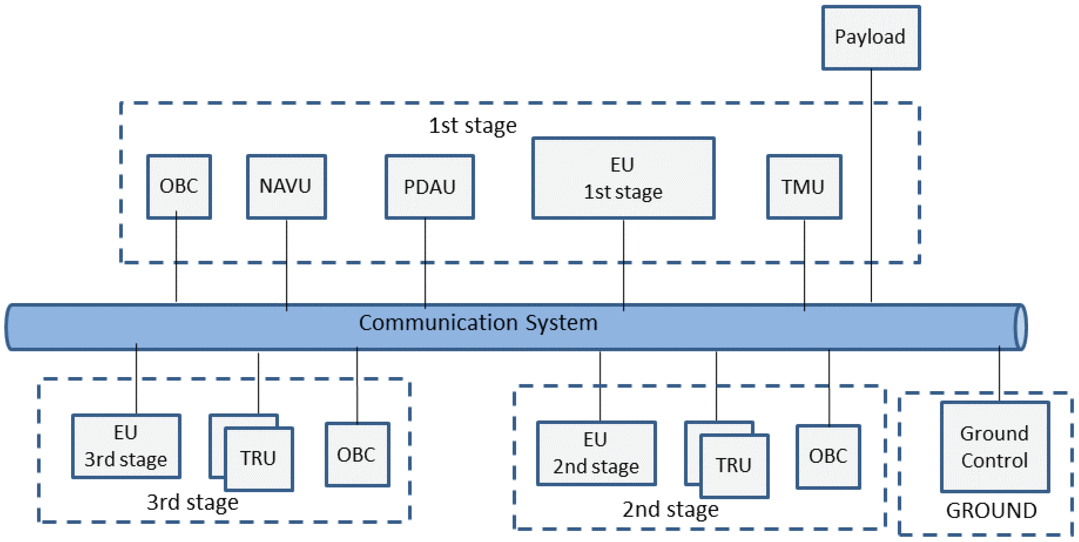
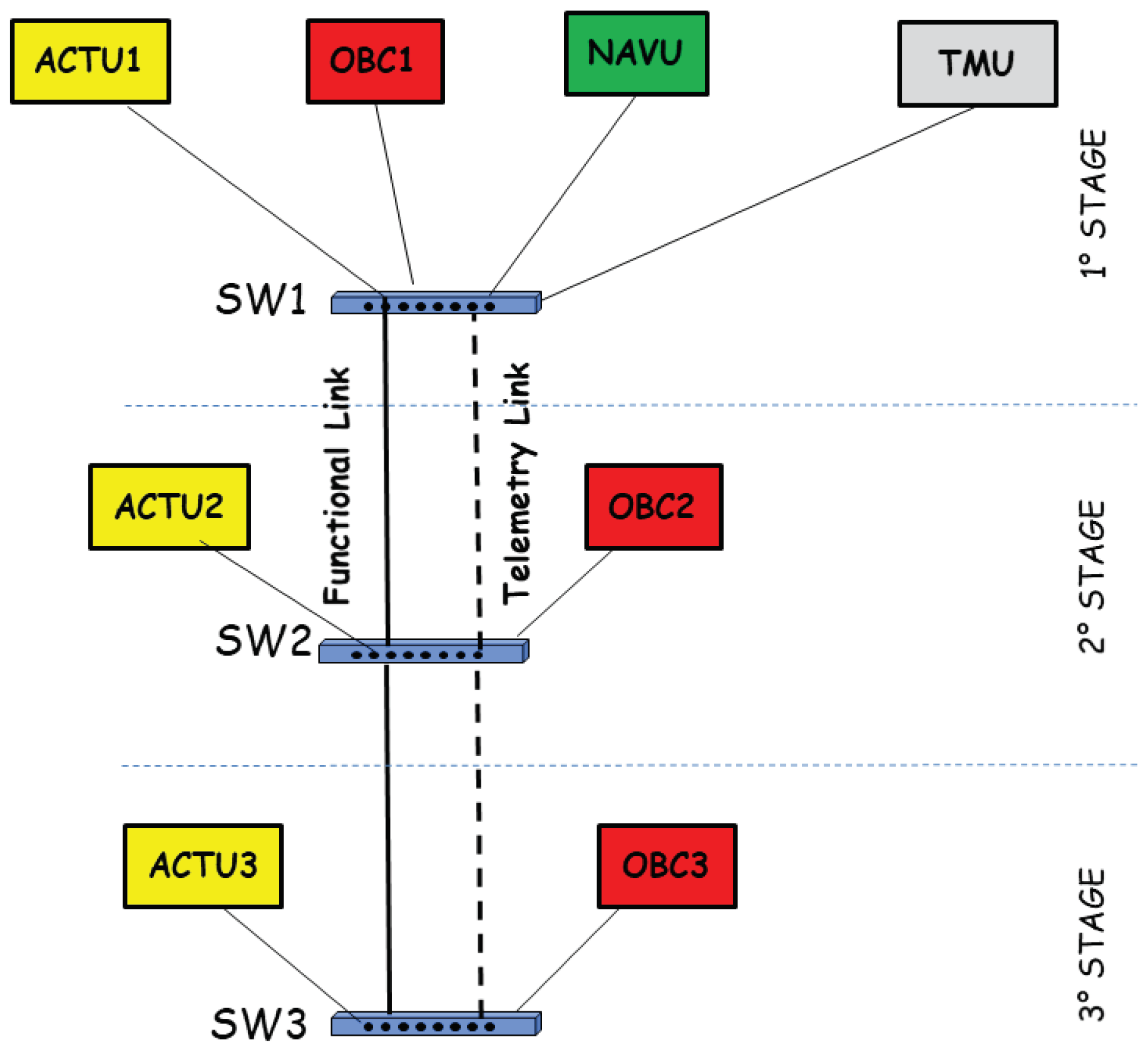
  • The Guidance, Navigation and Control (GNC) Subsystem, which groups sensors, actuators and data handling needed to perform a mission; it also includes the battery power sources;
  • The Telemetry Subsystem (TMS), which groups sensors, data handling and Radio Frequency (RF) telemetry transmission chain.
In particular, the GNC subsystem is comprised of the on board electrical and electronic pieces of equipment providing the launcher flight control. The GNC S/S and TLM S/S are both connected to the communication system. Their components are listed hereafter:
  • Navigation Unit (NAVU) with its flight software;
  • On Board Computer (OBC) with its flight software that will perform the GNC functions needed during the flight and the management of other functions of the launcher on the basis of a “mission timeline”;
  • Power Distribution and Actuation Unit (PDAU) that performs several actuations and operations needed by flight management (main engine firings, stage separations, etc.);
  • Thrust Vector Control (TVC) subsystems, one for each stage, comprised of one Electronic control Unit (EU) and one mechanical actuator;
  • Telemetry Master Unit (TMU) that receives telemetry messages from all of the terminals and send them to the ground station;
  • Ground Control (GC) that follows the preliminary and the first phases of the mission;
  • Telemetry Remote Units (TRUs) collect the sensor data from each stage and send the acquired information to the TMU; currently in the 1553B bus of VEGA [3], these units are connected to another communications system different from the one transporting GNC messages.
The terminals are involved in transferring three different type of messages:
  • GNC messages: they are needed for the guide, navigation and control operations;
  • telemetry messages: they are sent to Ground using the TMU equipment; the TMU will manage two types of data: (i) CVI (Control Visuel Immediate) transmitted to Ground, immediately visible on screen by mission control and used by Mission Control to decide the launch vehicle destruction in case of anomalies; (ii) CVD (Control Visuel Differe) transmitted to ground as soon as possible and stored on Ground for post-processing purposes.
  • sporadic messages: they belong to the sporadic sequences that are a set of predefined messages separated by predefined time intervals; a sequence is executed once, or more than once along the mission, to perform sporadic functional orders (e.g., stage separation, engine ignition, etc.).
The interest towards a novel communication architecture is due to the bandwidth limit of the communication systems for small launchers based on 1553B bus. This capacity is not higher than 1 Mb/s and it has been saturated. As a matter of example, the communication system would not be able to support new telemetry devices or new services. A TTEthernet-based solution [11,12] allows for the achievement of the goal with the introduction of devices (End Systems and Switches) able to allocate static bandwidth resources with the consequence of guaranteeing hard delay. The problem of TTEthernet is its high cost. For this reason we propose and evaluate a FTTE-based [13,14] communication architecture designed ad hoc for a launcher network and using COTS technology.

4. Flexible Time Triggered Ethernet Architecture for Nano/Micro Launcher Networks

The proposed FTTE-based architecture for Nano/Micro Launcher Networks is reported in Figure 2. The architecture is composed by three main planes:
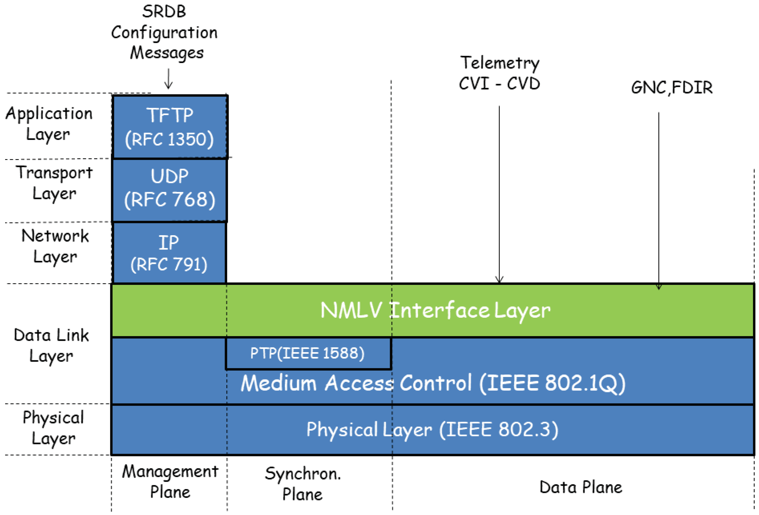
  • the data plane that delivers data messages and manages the message sending/receiving on redundant channels;
  • the synchronization plane that performs the synchronizations of local clocks of the end systems;
  • the management plane that configures the network, by updating/changing the System Requirement Database (SRDB) of a master node that stores the time instants in which the messages are scheduled to be sent.
Finally, we highlight that the switches implement the Medium Access Control (MAC) and physical layers only and support the synchronization protocol IEEE1588. For this reason, they are compliant with traditional COTS Ethernet switches. Both terminals and switch interfaces are configured as trunk mode ports of IEEE 802.1Q Virtual Local Area Network (LAN) [19]. In particular, each communication between source and destination ESs of the NMLV communication system is supported by a Virtual Local Area Network (VLAN) characterized by a VLAN Identifier [19].
Next we describe the Data Link Layer of the proposed NMLV architecture in Section 4.1 while an example of network operation mode is illustrated in Section 4.2.

4.1. Data Link Layer

In the general architecture of the NMLV Communication System, we define two sublayers: the traditional Medium Access Control (MAC) layer based on the IEEE 802.1Q [19] and the NMLV Interface Layer. The IEEE 1588 Synchronization layer is also introduced in the architecture to allow the synchronization of the network nodes so as to guarantee the support of the real-time layer service. The integration of the offered services needs the definition of a sophisticated scheduling of the MAC frames in end systems. We describe the IEEE 802.1Q and the NMLV Interface layers in Section 4.1.1 and Section 4.1.2 respectively. The scheduling functionality is briefly illustrated in Section 4.1.3.

4.1.1. IEEE 802.1Q Layer

The architecture of the NMLV communication system is based on full-duplex operation that does not require the support of the collision handling functions. In the NMLV Communication System, the MAC layer is based on IEEE 802.1Q that is the standard for tagging frames on a trunk (aggregation of flows with the same path and characterized by the same QoS parameters) and support up to 4096 VLANs. The IEEE 802.1Q frame structure is reported in Figure 3. Beyond the Ethernet traditional fields, the IEEE 802.1Q frame includes the VLAN tag of 4 bytes, characterized by the following fields:
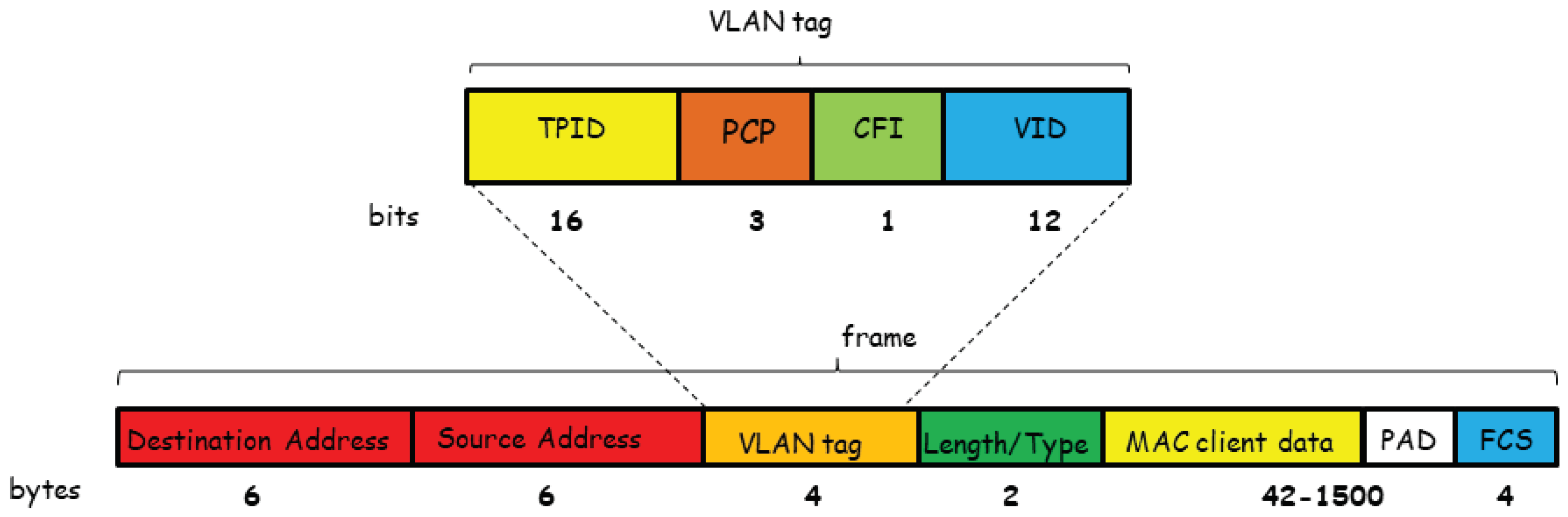
  • Tag Protocol Identifier (TPID) is a 16-bit field set to a value of 0x8100 in order to identify the frame as an IEEE 802.1Q-tagged frame;
  • Priority Code Point (PCP) is a 3-bit field which refers to the IEEE 802.1p class of service priority. This field indicates the frame priority level which can be used to support different QoS, in terms of delivery delay;
  • Canonical Format Indicator (CFI) is a 1-bit field that indicates if the MAC address is in non canonical (1) or canonical (0) format;
  • VLAN Identifier (VID) is a 12-bit field that uniquely identifies the VLAN to which the frame belongs.

4.1.2. NMLV Interface Layer

The introduction of the NMLV Interface layer leads to real-time behavior guarantees for the communication system. It inherits the functionalities of the FTTE standard described in [13]. The main differences could be summarized as follows:
  • we remove the polling requests mechanism of the asynchronous window in the NMLV; we assume that all of the real-time traffic is periodic and a priori scheduled so as to emulate the circuit behavior of the traditional communication system for launch vehicles as 1553B bus [2];
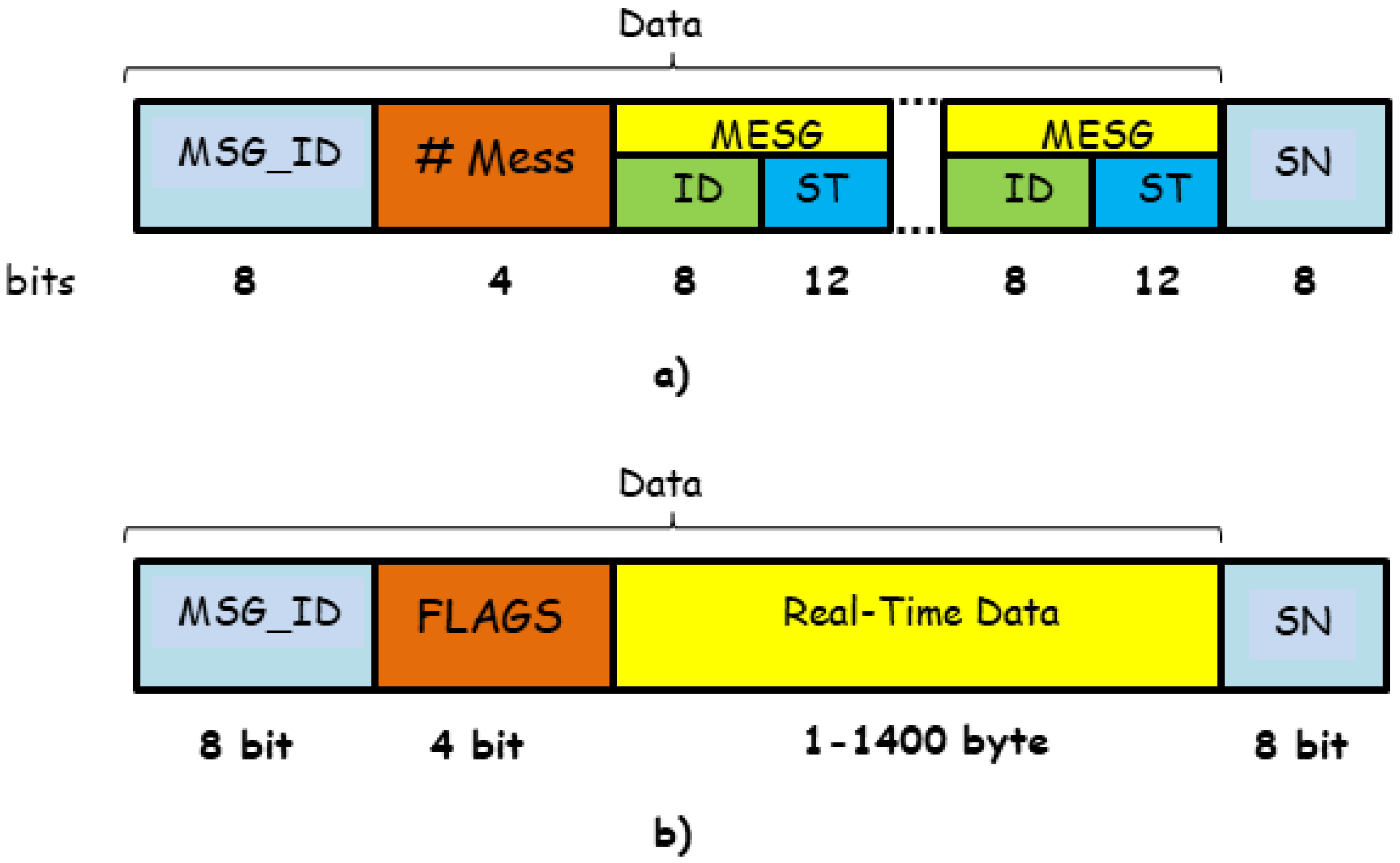
  • the NMLV layer supports the spatial redundancy [12] and end systems has to send the message on two output interfaces and to number the messages so that the receiving End System (ES) is able to recognize two copies of a same message; for this reason, a Sequence Number (SN) field is inserted in the NMLV Protocol Data Unit (PDU);
  • the NMLV layer defines the scheduling instants for the messages so as to exploit the filtering operation of the switches and allowing for the parallel sending of messages that have no common links on their path connecting the source and destination ESs; that leads to an increase in the bandwidth use.
The NMLV layer has one layer service only referred to as Real-Time Layer Service (RT-LS). It allows for frame delivery with deterministic delay and limited jitter. It is offered to periodic messages flows. The frames are sent/received to/by the end systems in off-line scheduled time intervals; the successfully delivering of frames is possible if the involved networks elements (end systems and switches) are correctly synchronized by the synchronization protocol. The frame delivery instants are determined by a scheduling algorithm. The frames in which the messages requiring RT-LS are inserted is based on the IEEE 802.1Q standard frame and the NMLV PDUs are represented in Figure 4. Two types of NMLV PDUs are defined. They are referred to as Triggered and Real-Time Messages and are reported in Figure 4a,b respectively. For each field of the messages, we also report its length (bit or bytes). In both message types, the first field (MSG_ID) identifies the message type. The FTTE protocol organizes the message transmission in periods of equal duration and referred to as Elementary Cycles (EC). At the beginning of every EC, the Triggered message is sent by a Master ES. It notifies the ESs with the instants in which they have to start their transmission. Then the next fields of the MSG_ID in the Triggered Message contain the number of data messages that should be transmitted in that EC and, for each of these messages, the respective ES identifier (ID) and sending time (ST). The Real-Time message frame contains flags (FLAGS) and data fields (Real-Time Data) respectively.
Finally, a Sequence Number (SN) is added at the end of each type of message to handle the spatial redundancy [11,12].

4.1.3. Scheduling Functionality

The synchronized local clocks and the pre-configured schedule specify the temporal position of the Real-Time frames on the timeline. The sending times are a priori scheduled and all information are contained in the System Requirement Database of the Master End System (ME) of each stage. In every EC, the ME has to prepare the Triggered Message for that EC that contains the transmission instants for the enabled communications in that EC and disseminates it to the Slave End Systems. An heuristic for the determination of the message scheduling instants that avoids link contentions is proposed in Section 5. The proposed heuristic is bandwidth effective because it takes into account the filtering capacity of the Ethernet switches and allows for the parallel delivery of messages with different source and destination ESs.

4.2. Network Operation Mode

We illustrate the network operation mode in the case of the simple network of Figure 5 equipped with five ESs (Master ES, ES-A, ES-B, ES-C, ES-D) and one switch (SW). We assume that three messages M1, M2 and M3 have to be transferred, between the ES tuples ES-A-ES-B, ES-D-ES-C, ES-A-ES-C. We also assume that all of the messages have the same length and the transferring total time, including processing, transmission and propagation times, is equal to 10 μs. The Master End System emits the Triggered Message (TM) to all of the ESs; the scheduling times of M1, M2 and M3 are reported in it.
Each ES has a table reporting the VID of the VLANs in which its messages have to be transferred. These VIDs are the ones associated to the VLAN interconnecting the source ES and the destination ESs of the message. As a matter of example, we report the tables of ES-A and ES-D in Figure 6a,b. Finally, the switch is configured so as to support the VLANs needed to interconnect the ESs. We report in Figure 6c the switch table with the values of VIDs concerning the VLANs on which the messages M1, M2 and M3 have to be transferred.
The network operation mode can be summarized as follows:
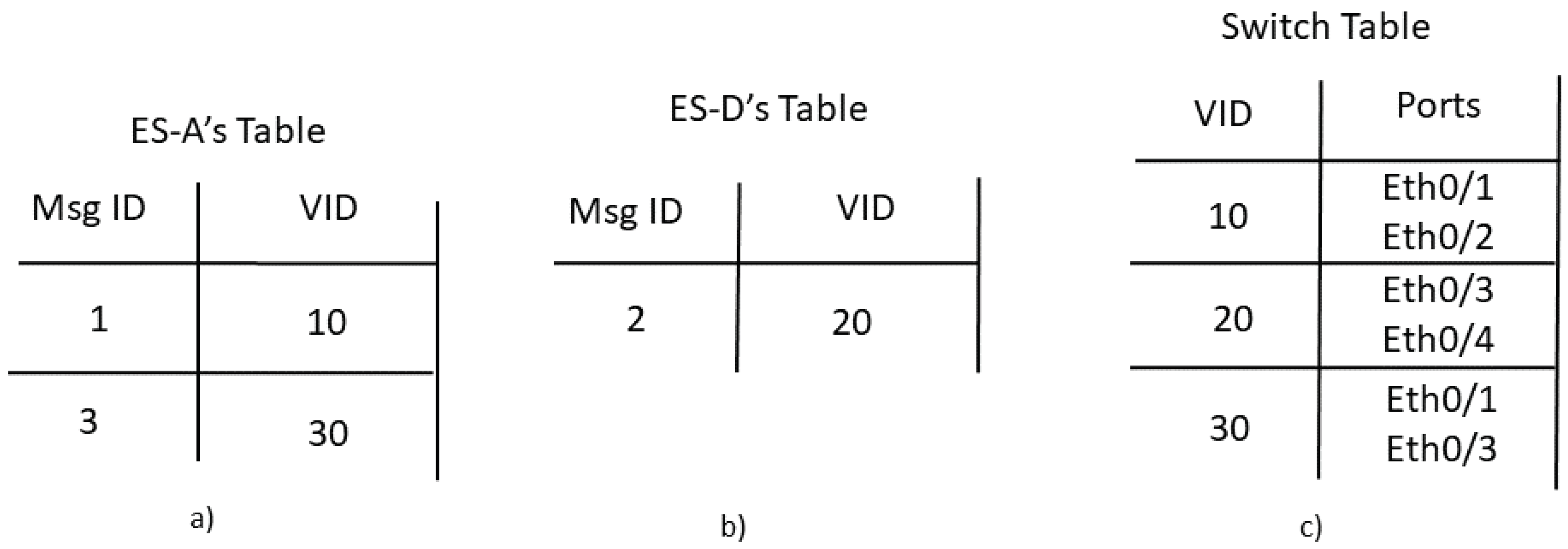
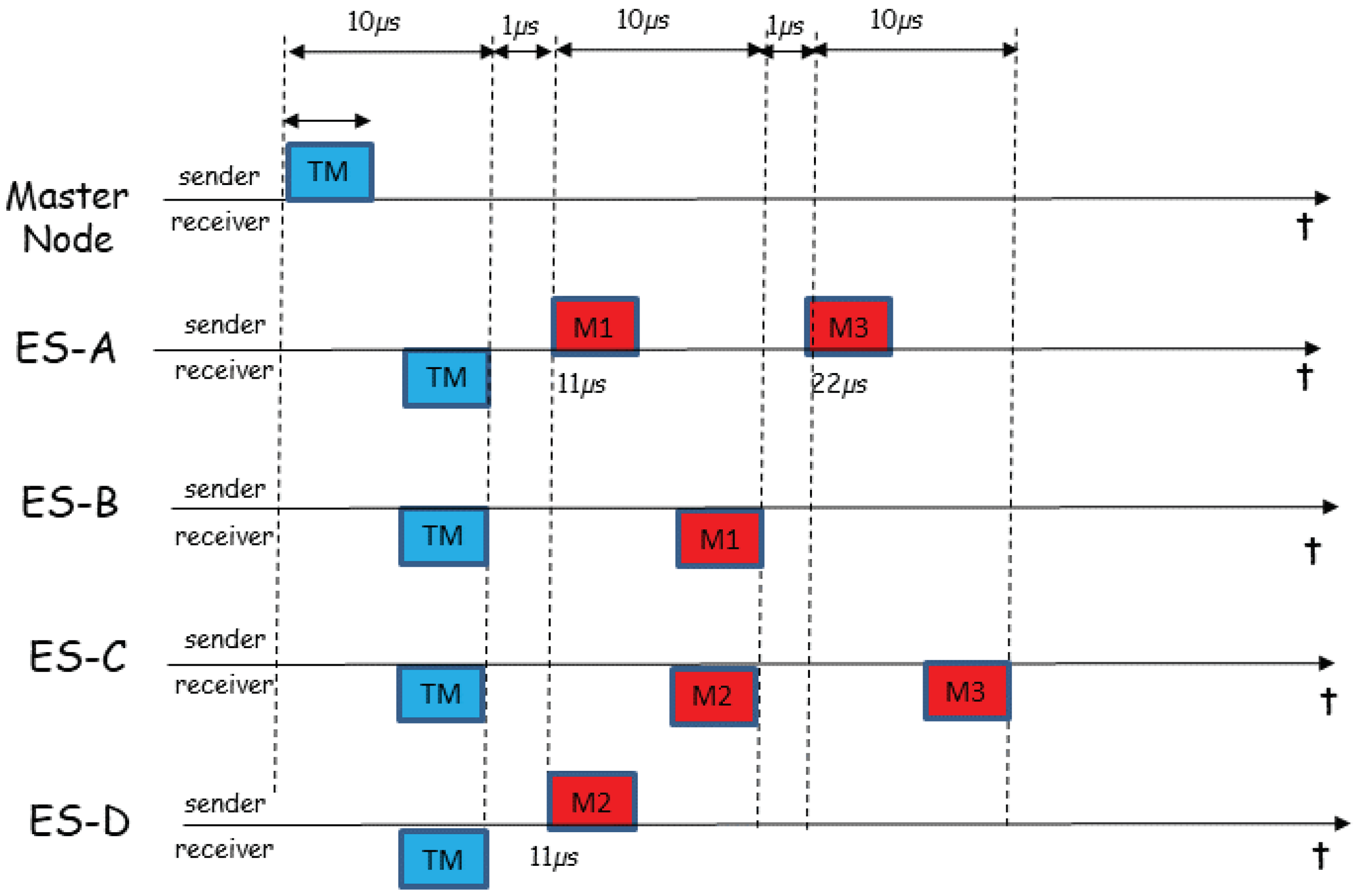
  • The master ES applies the NMLV scheduling algorithm and determines the sending instants of the messages M1, M2 and M3; the application of the algorithm may lead to the scenario reported in Figure 7 where the message scheduling instants that avoid contention on the network links may be t M 1 = 11 μs, t M 2 = 11 μs and t M 3 = 22 μs;
  • The master ES sends the TM, enveloped in an 802.1Q frame, to all ESs in the network; the TM is shown in Figure 8; it provides information on the sending time of the three messages M1, M2 and M3;
  • The ES-A sends in the instants t M 1 = 11 μs and t M 3 = 22 μs the messages M1 and M3 respectively, while the ES-B sends in the instant t M 2 = 11 μs the message M2; the messages M1, M2 and M2 are carried in 802.1Q frames with VID equal to 10, 20 and 30 respectively.

5. Heuristic for Message Scheduling

The objective of the heuristic is to schedule the instants in which the ESs have to transmit the messages so as to avoid bandwidth contentions in any network link. We assume that the time axis is organized in ECs numbered with an integer starting from the value 0. Because most of sensor and actuation messages of a launch vehicle are periodically sent, we assume periodical messages. Next we introduce the following input parameters of the heuristic:
  • T E C : EC duration time;
  • P: number of message types, each one characterized by a certain periodicity;
  • T j ( j = 1 , , P ) : period of the i-th type messages expressed in terms of number of ECs; we assume that the values T j ( j = 1 , , N p ) are ordered in increasing order ( T 1 < , T j < , P ) ;
  • Q: Multiple Common Minimum of the values T j ( j = 1 , , P ) ;
  • Λ i , j ( i = 0 , , Q 1 ; j = 1 , , P ) : set of messages of period M j and with offset i; that is to say that the messages of the set Λ i , j have to be sent in the ECs i + k M j ( k = 0 , 1 , ) ;
  • Π m : network path in which the message m has to be routed; Π m is composed by a set of network links;
  • S m : ES emitting the message m.
The outputs of the heuristic are the scheduling instants T m of the messages m Λ i , j ( i = 0 , , Q 1 ; j = 1 , , P ) , evaluated starting from the beginning of any EC in which m has to be sent. The determination of T m will lead to send the messages in the instants i T E C + T m + k T j T E C ( k = 0 , 1 , ) .
The proposed heuristic is applied in each EC and its goal is the one to first select the messages than can be sent earlier by avoiding any link contention. It is based on the following variables:
  • t S : transmission end instant of the last message sent by the ES S; this variable is updated every time in which the heuristic decides for the scheduling of a message emitted by the ES S;
  • Γ L : set of messages that have already been scheduled and use the network link L;
  • Ω r : higher time instant in which the message r has been completely received by the destination ESs.
The main steps of the heuristic are described in Algorithm 1.
Algorithm 1Heuristic for Message Scheduling
1:
Input: set Λ i , j ( i = 0 , , Q 1 ; j = 1 , , P )
2:
i = 0 ; j = 1
3:
while j P do
4:
while i Q 1 do
5:
  while Λ i , j do
6:
   Initialize Λ a u x = Λ i , j
7:
   while Λ a u x do
8:
    Choose n Λ a u x
9:
    Set Λ a u x = Λ a u x { n }
10:
     T n = max ( t S n , max L P n , r Γ L Ω r ) ;
11:
   end while
12:
    m = arg min n Λ i , j T n ;
13:
   Set T m = min n Λ i , j T n
14:
   Set Λ i , j = Λ i , j { m }
15:
  end while
16:
   i = i + 1
17:
end while
18:
j = j + 1
19:
end while
20:
Output: T m m Λ i , j ( i = 0 , , Q 1 ; j = 1 , , P )
Λ a u x is an auxiliary variable. The heuristic chooses to schedule the messages in increasing order of periodicity (Line 2) and next in order increasing of EC index (Line 4). For all of the messages n in the set Λ i , j not scheduled yet, the heuristic evaluates the first instant T n in which the message n can be sent (Line 10) so as to avoid bandwidth contentions in any network link L of the path P n in which the message n has to be routed. To guarantee contention lack, the message has to be sent after the transmission end instant of all of the messages already scheduled on the path P n . Among the messages n the heuristic schedules, the one with smaller T n (Line 12). The operation is repeated for the remaining messages until the set Λ i , j becomes empty (Line 5).
From the steps performed in the Algorithm 1 we can notice that: (i) the first while cycle performs P times (Line 3); (ii) the second while cycle performs Q times (Line 4); (iii) the scheduling instant of one message at a time is evaluated for the set Λ i , j (Line 5); (iv) the evaluation of each of these scheduling instants involve, for each message not scheduled yet, the evaluation of the earliest instant in which the message can be sent without causing contention on any output link of the message (Lines 7 and 12); (v) the evaluation of this earliest time is evaluated by performing as many maximum operations as the length of the message path (Line 10). According to these remarks, if we denote with N Λ the maximum of the cardinality of the sets Λ i , j ( i = 0 , , Q 1 ; j = 1 , , P ) and with ξ the length of the longest expressed as number of hops, we can conclude that the computational complexity of the proposed heuristic is O ( P Q N Λ 3 ξ ) .

6. Numerical Results

We report some results on the bandwidth efficiency that the proposed solution for realizing the NMLV communication system allows us to achieve. In particular, we compare three solutions:
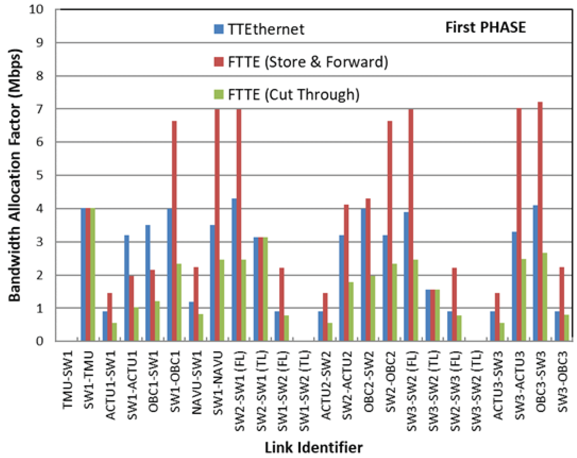
  • a FTTE-based solution with the use of store and forward traditional Ethernet switches and when the scheduling heuristic of Section 5 is applied;
  • a FTTE-based solution with the use of cut-through Ethernet switches and when the scheduling heuristic of Section 5 is applied; the cut-through solution allows for the minimization of the switch forward delay because the frame can be forwarded not just when the frame header is read;
  • a TTEthernet-based solution [12] with the application of a scheduling heuristic similar to the one illustrated in Section 5 by taking into account that the TTEthernet switch allows the introduction of offset times [12] to solve the bandwidth contentions in the network links; obviously this solution is bandwidth effectiveness but its disadvantage is the higher cost considering that a TTEthernet switch can cost up to 40 times the cost of a traditional Ethernet switch.
We consider the network topology of Figure 9. It is composed by three switches denoted as SW1, SW2 and SW3 respectively and three stages with one switch in each of them. The Navifation Unit (NAVU) is attached to the switch of the first stage as well as an On-Board Computer (OBC) (OBC1 for the first stage), the Telemetry Master Unit (TMU) and an Actuation Unit (ACTU) (ACTU1 for the first stage). In the other remaining stages, one OBC (OBC2 and OBC3 for the second and third stages respectively) and one ACTU (ACTU2, ACTU3 for the second and third stages respectively) are attached. The messages sent to the TMU only, can be routed only using the telemetry links through the switches SW1, SW2, SW3. The links interconnecting these switches are duplicated so as to route on different network paths the GNC and FDIR messages and the ones directed to the TMU only. The messages directed to the TMU do not need to be delivered with hard delay.
We consider a real traffic scenario and requirements. In particular, we have considered a set of GNC and telemetry messages extrapolated by the VEGA message set [3]. We report in Table 2 the characteristics of the GNC and telemetry messages respectively. For each message we report the source and destination terminals, the message length (byte), the period and the offset expressed in terms of number of ECs. We assume the EC duration time of 4.9996 ms, which is equal to one of the minor frames in VEGA [3]. The link bandwidth is 100 Mbps.
We have evaluated three flight phases referred to as Phase-1, Phase-2 and Phase-3. In particular, Phase-1 is the one in which all of the three stages are attached, Phase 2 is the one in which the Stage-3 is detached while Phase-3 is the one in which both Stage-2 and Stage-3 are detached. Let us introduce for each link the Bandwidth Allocation Factor (BAF). It characterizes the consumed effective bandwidth including both the one needed to carry the messages and the one not used to avoid contentions on any link. The performance comparison between TTEthernet and FTTE is reported in Figure 10, Figure 11 and Figure 12 for Phase-1, Phase-2 and Phase-3 respectively. We show the BAF as a function of the network links denoted with the network elements (ES and switches) interconnecting them. For the tuple of switches SW1-SW2 and SW3-SW3, we report four values of BAF relative to the link directionality and the link type (Functional and Telemetry).
As expected, from Figure 10, Figure 11 and Figure 12, we can notice how the FTTE solution with Store and Forward switches is the least bandwidth effective one in Phase-1 and Phase-2 because differently from TTEthernet solution, the message scheduling is only implemented in the ESs. However, it increases by only a few Mbps the BAF with respect to TTEthernet solution but with a big advantage of costs given the possibility to exploit COTS devices and in particular traditional Ethernet switches. Furthermore, we notice how the FTTE (Store and Forward) performance significantly improves in Phase-3 where the detachment of the first two stages allows for smaller network delays that consequently leads to better performance of the scheduling algorithm. In Phase-3, even better performance than the TTEthernet can be obtained. The worse performance of TTEthernet is due to the Timely Blocking problem that leads to the bandwidth inefficiency caused by empty intervals introduced by the switches to guarantee hard delay [20,21,22]. For instance, BAF of 1.91 Mbps and 3.50 Mbps are obtained in the OBC1-SW1 link for FTTE (Store and Forward) and TTEthernet solutions respectively.
Finally, we can observe how the FTTE solution with Cut Through switches allows for a remarkable reduction in BAF. For some links this solution allows for better BAF values with respect to the TTEthernet solution. For instance, in the case of Phase-2, for the NAVU-SW1 link, we have BAF values of 0.25 Mbps and 1 Mbps for the FTTE (Cut & Through) and TTEthernet solutions respectively.

7. Experimental Test-Bed

Next we describe the Demonstrator Hardware/Software in Section 7.1. The Test Configurations and some experimental results on delay and jitter are illustrated in Section 7.2.

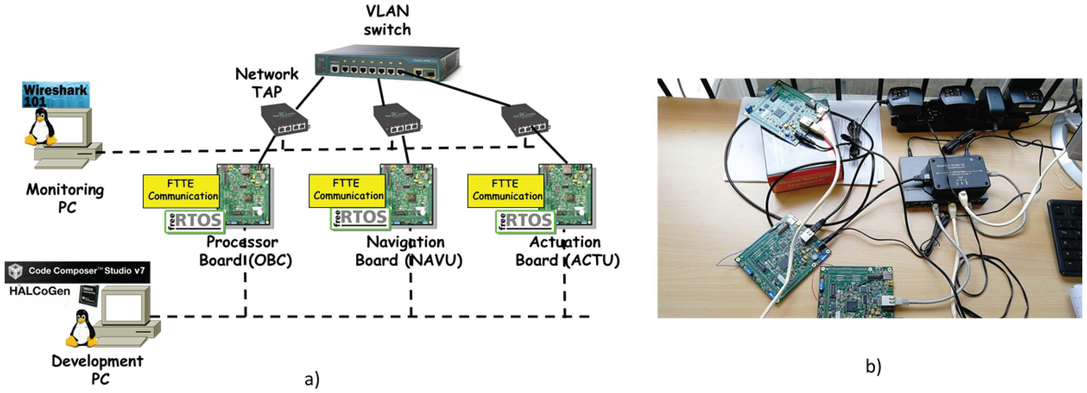
7.1. Demonstrator Hardware/Software

The demonstrator allows for the experimental evaluation of a single flight stage and consists of the following parts:
  • Three Hercules TMS570 MCU Development Kits. They emulate an OBC, a NAVU and an ACTU respectively; the development board includes an on-board XDS100v2 JTAG emulator, access to connectivity peripherals and access to all other peripheral pins; the kits also include a DC power supply, cables, software environment, demo software and code examples;
  • Ethernet Switch. It is based on COTS technology and implements VLAN;
  • Network Monitoring PC. It is a PC connected to the same Ethernet network as the units under test by means of network tap and in order to spy on the traffic using Wireshark. The test support software will be mainly composed by GNC and telemetry traffic generator and software for the and frame delivery time and loss measurement in order to verify the correctness of the network operation mode. Some test configurations will be defined in Section 7.2;
  • Development PC. It is a PC containing the Software Development Environment (SDE); it is used to code, build, run and debug software on the target platforms.
The FTTE communication library is realized in C programming language. The library allows managing the deterministic communication on Ethernet and will be shared by all the applications. Typical services exposed by this library allows sending/receiving message, configuring the network, etc.
The development environment is developed in C programming language. It is composed by three components:
  • FreeRTOS Operating System [23]. The Operating System shall be FreeRTOS executed on the top of Hercules board. FreeRTOS is a real-time operating system kernel for embedded devices that has been ported to about 35 microcontrollers. FreeRTOS kernel itself consists of only three C files. To make the code readable, easy to port, and maintainable, it is written mostly in C, but there are a few assembly functions included. FreeRTOS provides methods for multiple threads or tasks, mutexes, semaphores and software timers. A tick-less mode is provided for low power applications. Thread priorities are supported.
  • HALCoGen [24]. It is an application that represents the Hardware Abstraction Layer Code Generator of the Hercules board. HALCoGen provides a graphical user interface that allows the user configuring peripherals, interrupts, clocks, and other microcontroller parameters. Once the device is configured, the user can generate peripheral initialization and driver code, which can be imported into Code Composer Studio. It is important to underline that HALCoGen includes support for FreeRTOS. Indeed, the configuration generated with Halcogen allows completely setting the Hercules board, also taking on the role that is usually played by the Firmware.
  • Code Composer Studio [25]. It is an integrated development environment (IDE) that supports development of applications on Texas Instruments microcontrollers and embedded processors. It is based on Eclipse and comprises a suite of tools used to develop and debug embedded applications. It includes an optimizing C/C++ compiler, source code editor, project build environment, debugger, profiler, and many other features. Code Composer Studio communicates with the board for programming and debug using USB XDS100v2 JTAG.

7.2. Tests Description and Results

The sent/received messages are structured as described in Section 4.1.1 and Section 4.1.2 and are reported in Table 3. For each of them we report: the message name, the VLAN ID field of Figure 3, the MSG_ID field of Figure 4, the sources and destination ESs, the period and the Offset expressed in terms of number of ECs whose duration is the one of the Minor Frame in VEGA launcher Table 3 that is 4.999 ms. Furthermore, Table 3 also reports the message scheduling time evaluated at the beginning of the EC.
The function of each message is the following:
  • NMLV_TM is the Time Triggered Message that coordinates the messages transmission so as to avoid any bandwidth contention; its length depends on the number of messages transmitted in the EC in which NMLV_TM is sent;
  • ACTU_C_EV is the message sent from the OBC to the ACTU to switch on/off the Electro-Valves (EV); we assume that the Real_Time field length (Figure 4) of the message equals 8 bit with possibility to switch on/off up to eight EVs;
  • ACTU_C_TVC is the message sent from the OBC to the ACTU to pilot the Electro-Mechanical-Actuator (EMA) of the TVCs; we assume that the Real_Time field length (Figure 4) of the message equals 9 bytes: one flag byte and a couple of 4 bytes, each one reporting a float that express in mm the displacement of an EMA;
  • NAVU_R_data is the message sent from the NAVU to the OBC to provide the estimation of altitude, position and velocity of the NMLV by the navigation function; we assume that the Real_Time field length (Figure 4) of the message equals 72 bytes.
We perform three tests:
  • Test-A: the network tap of Figure 13 is inserted between the Processor Board and the Ethernet switch and the following messages are collected: NMLV_TM, ACTU_C_EV, ACTU_C_TVC (emitted by the OBC) and NAVU_R_data (received by the OBC);
  • Test-B: the network tap of Figure 13 is inserted between the Navigation Board and the Ethernet switch and the following messages are collected: NMLV_TM (received by the NAVU) and NAVU_R_data (emitted by the NAVU);
  • Test-C: the network tap of Figure 13 is inserted between the Actuation Board and the Ethernet switch and the following messages are collected: NMLV_TM, ACTU_C_EV, ACTU_C_TVC (emitted by the OBC).
The objective is the measure of the mean and the standard deviation of the inter-arrival times of the messages; the measured values are reported in Table 4.
We can observe how the implementation of the FTTE protocol allows for a correct delivery of the messages with the correct periodicity and a negligible standard deviation.

8. Conclusions

We have proposed an Ethernet-based communication system to be implemented in Nano and Micro Launch Vehicle. Its performance has been evaluated by simulation and with the realization of an experimental test-bed. The achieved results show how the proposed solution is bandwidth effective and allows for a performance comparable to very expensive solutions, such as TTEthernet. In particular, we have shown how the FTTE solution is more bandwidth effective in the flight phases in which some stages of the launcher have detached and the network is smaller so as to improve the performance of the scheduling algorithm which the FTTE protocol is based on. The results of the demonstrator, equipped with Ethernet switches and Hercules boards by Texas Instruments, have proved the feasibility of the proposed solution.
We hope that the positive results reported in this manuscript on the Flexible Time Triggered Ethernet can contribute to sensitizing the beginning of a standardization activity that is currently absent.

Author Contributions

V.E. has organized and written the paper. F.G.L. and F.V. have implemented and carried out the performance comparison of the TTEthernet and FTTEthernet solutions. F.G.L. and A.P. have implemented the experimental test-bed. S.C. have provided useful comments for the results section.

Funding

This research was funded by European Space Agency grant number ITT ESA AO/1-8275/16/NL/FE.

Conflicts of Interest

The authors declare no conflict of interest.

References

  1. Wekerle, T.; Filho, J.B.P.; da Costa, L.E.V.L.; Trabasso, L.G. Status and Trends of Smallsats and their Launch Vehicles: An Up-to-date Review. J. Aerosp. Technol. Manag. 2017, 3, 269–286. [Google Scholar] [CrossRef]
  2. Wu, K.; Jiang, J.; Hu, M. Intelligent fault-tolerant 1553B bus system based on adaptive learning. In Proceedings of the 2011 IEEE third International Conference on Communication Software and Networks (ICCSN), Xi’an, China, 27–29 May 2011; pp. 378–381. [Google Scholar]
  3. Accettura, A.; Balduccini, M.; Carducci, F.; De Lillis, A.; D’Aversa, E. VEGA: The History of an European Success. In Proceedings of the 2012 IEEE First AESS European Conference on Satellite Telecommunications (ESTEL), Rome, Italy, 2–5 October 2012. [Google Scholar]
  4. Sandic, M.; Teslic, N.; Velikic, Y. Bandwidth utilization in deterministic networks. In Proceedings of the 2016 Zooming Innovation in Consumer Electronics International Conference (ZINC), Novi Sad, Serbia, 1–2 July 2016. [Google Scholar]
  5. Nguyen, N.T.; Leu, M.C.; Liu, X.F. RTEthernet: Real-time communication for manufacturing cyberphysical systems. Trans. Emerg. Telecommun. Technol. 2018, 29, e3433. [Google Scholar] [CrossRef]
  6. IEEE802.3-2005, IEEE Standard for Ethernet. 2005. Available online: https://standards.ieee.org/about/get/802/802.3.html (accessed on 10 July 2018).
  7. Decotignie, J.D. The many faces of Industrial Ethernet. IEEE Ind. Electron. Maga. 2009, 3, 8–19. [Google Scholar] [CrossRef]
  8. ARINC 644 Part 7, Aircraft Data Network Part 7 Avionics Full Duplex Switched Ethernet (AFDX) Network. 2007. Available online: http://standards.globalspec.com/std/204622/arinc-664-p7 (accessed on 10 July 2018).
  9. SAE AS6802, Time-Triggered Ethernet. 2011. Available online: http://standards.sae.org/as6802/ (accessed on 10 July 2018).
  10. Steiner, W.; Bauer, G.; Hall, B.; Paulitsch, B. Triggered Ethernet: TTEthernet; CRC Press: Boca Raton, FL, USA, 2011. [Google Scholar]
  11. Eramo, V.; Lavacca, F.G.; Listanti, M.; Caporossi, S. Performance Evaluation of TTEthernet-based Architectures for the VEGA Launcher. In Proceedings of the 2018 IEEE Aerospace Conference, Big Sky, MT, USA, 3–10 March 2018. [Google Scholar]
  12. Eramo, V.; Lavacca, F.G.; Listanti, M.; Caporossi, S. TTEthernet: A Networking Technology for the support of Real-Time Services in Launcher Networks. IEEE Aerosp. Electron. Syst. Mag. 2018. [Google Scholar] [CrossRef]
  13. Pedreiras, P.; Gai, P.; Almeida, L.; Almeida, G. FTT-Ethernet: A flexible real-time communication protocol that supports dynamic QoS management on Ethernet-based system. IEEE Trans. Ind. Inf. 2005, 1, 162–172. [Google Scholar] [CrossRef]
  14. Derasevic, S.; Barranco, M.; Proenza, J. Designing fault-diagnosis and reintegration to prevent node redundancy attrition in highly reliable control systems based on FTT-Ethernet. In Proceedings of the 2016 IEEE World Conference on Factory Communication Systems (WFCS), Aveiro, Portugal, 3–6 May 2016; pp. 1–14. [Google Scholar]
  15. Decotignie, J.D. Ethernet-Based Real-Time and Industrial Communications. Proc. IEEE 2005, 93, 1102–1117. [Google Scholar] [CrossRef] [Green Version]
  16. Haverty, M. MIL-STD 1553—A standard for data communications. Commun. Broadcast. 1986, 10, 29–33. [Google Scholar]
  17. IEEE Std 802.1AS-2011—IEEE Standard for Local and Metropolitan Area Networks—Timing and Synchronization for Time-Sensitive Applications in Bridged Local Area Networks. Available online: https://standards.ieee.org/findstds/standard/802.1AS-2011.html (accessed on 10 July 2018).
  18. Song, M.; Yang-Scharlotta, J.Y.; Ashtijou, M.; Mojarradi, M. Evaluation of Commercial-Off-The-Shelf (COTS) Electronics for Extreme Cold Environments. In Proceedings of the 2018 IEEE Aerospace Conference, Big Sky, MT, USA, 3–10 March 2018. [Google Scholar]
  19. IEEE8021.Q, IEEE Standard for Local and Metropolitan Area Networks Bridges and Bridged Networks. 2014. Available online: https://ieeexplore.ieee.org/browse/standards/get-program/page/series?id=68 (accessed on 10 July 2018).
  20. Suethanuwong, E.; Hirunmutrapom, S.I. Searching of Best-effort Messages in TTEthemet Switches during the Timely Blocking Intervals. In Proceedings of the 2016 IEEE RIVF International Conference on Computing and Communication Technologies, Research, Innovation, and Vision for the Future, Hanoi, Vietnam, 7–9 November 2016. [Google Scholar]
  21. Suethanuwong, E. Message Fragmentation of Event-Triggered Traffic in TTEthernet Systems Using the Timely Block Method. In Proceedings of the 2016 International Conference on Computational Techniques in Information and Communication Technologies (ICCTICT), New Delhi, India, 11–13 March 2016. [Google Scholar]
  22. Zhou, X.; He, F.; Wang, W. Using network calculus on worst-case latency analysis for TTEthernet in preemption transmission mode. In Proceedings of the 2016 10th International Conference on Signal Processing and Communication Systems (ICSPCS), Gold Coast, Australia, 19–21 December 2016. [Google Scholar]
  23. FreeRTOS Kernel, Software. Available online: https://www.freertos.org/ (accessed on 10 July 2018).
  24. HALCoGen: Hardware Abstraction Layer Code Generator for Hercules MCUs. Available online: http://www.ti.com/tool/HALCOGEN (accessed on 10 July 2018).
  25. Code Composer Studio (CCS) Integrated Development Environment (IDE). Available online: http://www.ti.com/tool/CCSTUDIO (accessed on 10 July 2018).
Figure 1. Terminals and communications system of a small launcher.
Aerospace 05 00084 g001
Figure 2. General Architecture of the NMLV Communication System.
Aerospace 05 00084 g002
Figure 3. IEEE 802.1Q Frame.
Aerospace 05 00084 g003
Figure 4. NMLV Protocol Data Unit. Triggered Message (a); Real Time Message (b).
Aerospace 05 00084 g004
Figure 5. Network example with five End Systems and one switch; the Triggered message is sent to all of the End Systems; three messages have to be transported.
Aerospace 05 00084 g005
Figure 6. ES-A (a) and ES-D (b) Tables reporting the VID for the transport of the messages M1, M2, M3. VLAN configuration in the switch (c).
Aerospace 05 00084 g006
Figure 7. Scheduling instants evaluated by the NMLV scheduling algorithm.
Aerospace 05 00084 g007
Figure 8. Field values of the Triggered Message.
Aerospace 05 00084 g008
Figure 9. Network Topology.
Aerospace 05 00084 g009
Figure 10. BAF as a function of the network links for the Phase-1.
Aerospace 05 00084 g010
Figure 11. BAF as a function of the network links for Phase-2.
Aerospace 05 00084 g011
Figure 12. BAF as a function of the network links for Phase-3.
Aerospace 05 00084 g012
Figure 13. Scheme (a) and Picture (b) of the Experimental Test-bed.
Aerospace 05 00084 g013
Table 1. List and meaning of acronyms.
AcronymMeaning
GNCGuide, Navigation and Control
TMSTelemetry Subsystem
NAVUNavigation Unit
OBCOn Board Computer
PDAUPower Distribution and Actuation Unit
TVCThrust Vector Control
EUElectronic Control Unit
TMUTelemetry Master Unit
GCGround Control
TRUTelemetry Remote Unit
PLPayload
Table 2. Launcher Messages. Source (S) and Destinations (D) of the messages are reported as well as their length (bytes), period and offset expressed in terms of number of ECs.
MessageSDLengthPeriodOffsetMessageSDLengthPeriodOffset
M1OBC1All4010M19OBC3TMU40082
ACTU1
M2OBC1TMU4010M20OBC3TMU40086
ACTU2
M3OBC2TMU4010M21NAVUTMU12882
ACTU3
M4OBC3TMU4010M22ACTU1TMU12884
ACTU1
M5OBC1TMU4083M23ACTU2TMU12884
ACTU2
M6OBC2TMU4083M24ACTU3TMU12884
ACTU3 ACTU1
M7OBC3TMU4083M25OBC1TMU4010
OBC1 ACTU1
M8OBC2TMU6441M26OBC1TMU4010
OBC3
OBC1 ACTU1
M9ACTU1TMU4085M27OBC1TMU4010
OBC2 ACTU2
M10ACTU2TMU4085M28OBC2TMU4010
OBC3 ACTU2
M11ACTU3TMU4085M29OBC2TMU4010
ACTU1 OBC1
M12OBC1NAVU4010M30OBC2OBC340010
TMU TMU
ACTU2 ACTU2
M13OBC2NAVU4010M31OBC2TMU4010
TMU
ACTU3 ACTU3
M14OBC3NAVU4010M32OBC3TMU4010
TMU
ACTU3
M15OBC1TMU40080M33OBC3TMU4010
OBC1
M16OBC1TMU40084M34OBC3TMU40010
ACTU3
M17OBC2TMU40081M35OBC3TMU4010
M18OBC2TMU40085
Table 3. Messages generated in the Experimental Test-Bed.
Message NameVLAN IDMSG_IDSource ESDestination ESPeriod (EC)Offset (EC)Scheduling Time (ms)
NMLV_TM101OBCACTB,NAVB100
ACTU_C_EV502OBCACTU101
ACTU_C_TVC505OBCACTU823
NAVU_R_data1708NAVUOBC411
Table 4. Mean and Standard Deviation of the message inter-arrival times for Test-A, Test-B and Test-C.
MessageTest-A Mean (ms)Test-A Standard Deviation (ms)Test-B Mean (ms)Test-B Standard Deviation (ms)Test-C Mean (ms)Test-C Standard Deviation (ms)
NMLV_TM4.99960.03374.99960.02624.99960.0227
ACTU_C_EV4.99870.06444.99870.0537
ACTU_C_TVC39.99030.107539.99180.4143
NAVU_R_data19.99890.474719.99960.1558

