Turbine Blade Tip External Cooling Technologies

1
Concepts NREC, White River Junction, Windsor, VT 05001, USA
2
Mechanical Engineering Department, Virginia Polytechnic Institute and State University, Blacksburg, VA 24061, USA
*
Author to whom correspondence should be addressed.
Aerospace 2018, 5(3), 90; https://doi.org/10.3390/aerospace5030090
Submission received: 13 July 2018
/
Revised: 12 August 2018
/
Accepted: 13 August 2018
/
Published: 26 August 2018
(This article belongs to the Special Issue Cooling/Heat Transfer)
Abstract
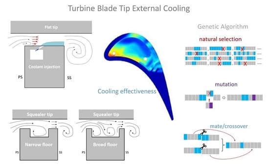
:This article provides an overview of gas turbine blade tip external cooling technologies. It is not the intention to comprehensively review all the publications from past to present. Instead, selected reports, which represent the most recent progress in tip cooling technology in open publications, are reviewed. The cooling performance on flat tip and squealer tip blades from reports are compared and discussed. As a generation conclusion, tip clearance dimension and coolant flow rate are found as the most important factors that significant influence the blade tip thermal performance was well as the over tip leakage (OTL) flow aerodynamics. However, some controversial trends are reported by different researchers, which could be attributed to various reasons. One of the causes of this disagreement between different reports is the lacking of unified parametric definition. Therefore, a more appropriate formula of blowing ratio definition has been proposed for comparison across different studies. The last part of the article is an outlook of the new techniques that are promising for future tip cooling research. As a new trend, the implementation of artificial intelligence techniques, such as genetic algorithm and neural network, have become more popular in tip cooling optimization, and they will bring significantly changes to the future turbine tip cooling development.
1. Introduction
Turbine inlet temperature (TIT) is one of the most critical parameters in the Bryton cycle of gas turbine engines. One way to increase the cycle efficiency is to increase the turbine inlet temperature, as illustrated in Figure 1. Here, a typical Brayton cycle T-S diagram chart visualizes the impact of higher turbine inlet temperatures on higher efficiency. Indeed, the area between the solid curves through points 1-2-3-4 represents the useful power generated by the turbine. The cycle efficiency can be calculated by dividing the area surrounded by curve 1-2-3-4-1 (red area) by the total area below curve 2-3 (blue area plus red area), being the heat input. The dash lines convey the cycle with increased TIT, and the new cycle efficiency is the area in 1-2′-3′-4-1 curves divided by the area below curve 2′-3′. It is easy to see how a higher turbine inlet temperature increases cycle efficiency. As are results of pursuing high efficiency and low CO2 emission in modern gas turbine engine design, TIT has been pushed to a level that most materials cannot withstand for long operation times without an effective cooling system. The high operating temperature combining with high aerodynamic loading and mechanical stress also challenge the blade material in other ways. Before the TIT approaches melting temperature, oxidization and erosion are usually taking place much earlier, and can cause engine failure, or shorten the engine life. It has been found some regions in the turbine is more likely subject to thermal damage, and the blades could only survive if these regions are effectively cooled. One of such regions is the blade tip.
Gas turbine blades usually have a clearance gap between the blade tip and the casing. This gap allows the blade rotates, as well as accommodates the mechanical and thermal expansions. Thus, the blade tip operates in a rapid transitional condition between the highest tangential speed region of the rotating airfoil and the stationary casing surface, which causes high aerodynamic load on the blade tip. On the other hand, as a result of pressure difference between the pressure side and the suction side, the hot flow leaks through this clearance gap. An illustration of tip leakage flow is given in Figure 2. Since the tip leakage flow causes significant amount of total pressure loss—up to one third of the entire stage total pressure loss, according to the report by Denton [1]—loss control had been the main objective of the aerodynamics studies on tip leakage flow. Different features like winglets and squealers, had been employed in the tip design, such as the work done by Yaras et al. [2], Heyes et al. [3], Ameri [4], Harvey et al. [5], and Schabowski and Hodson [6], to name a few of them.
Other than driving secondary flow in the passage and causing total pressure loss, tip leakage flow also brings in extra heat, and increases thermal load on the blade tip. Therefore, it is essential to cool the tip and to seal against the hot leakage flow simultaneously, which makes the blade tip one of the most complex regions to design. A review of the early studies of blade tip heat transfer before the 2000s can be found in Bunker’s report [7]. Tip heat transfer study was initialized by Mayle and Metzger during the early 1980s [8]. Their study revealed that the tip heat transfer was dominated by the tip leakage flow, which is mainly driven by the pressure difference between the pressure and suction side, and the blade rotating motion impact on the average tip heat transfer is secondary (this conclusion is still debatable according to the recent research reported by Rezasoltani et al. [9], especially for the cases where tip external cooling exists) As a result, more complicated tip heat transfer and cooling studies was able to be achieved in stationary, linear cascade wind tunnels. Due to the instrumentation limit, early studies either were performed in very low speed facilities with scaled models, or provided only scattered data points. For example, Thorpe et al. [10] measured the tip heat transfer using thin film thermal gauges and reported data at different locations along the blade-tip mean camber line. Later on, more advanced equipment and techniques have been employed in tip heat transfer study, such as liquid crystal technique and infrared camera. As the consequence, more detailed views of the tip heat transfer were able to be visualized. Bunker et al. [11] reported probably the first 2D contour of heat transfer coefficient on the entire tip surface under a near engine condition test (cascade exit Mach number 0.75). In their tests a thin foil heater was embedded in the tip surface, and the liquid crystal technique was painted on the tip surface to display the surface temperature and heat flux. Since the last decade, many novel transient techniques have been developed that allow researchers to record heat transfer data on complicated surfaces with less limits on the wind tunnel conditions. For instance, Ekkad and Han [12] reported a transient liquid crystal thermography technique for the gas turbine heat transfer experiments. In their technique, the color change of the liquid crystal coating is measured using an image processing system, and the heat transfer coefficients are calculated using a heat flux reconstruction algorithm, based on an assumption of one-dimensional thermal conduction in the surface material. Xue et al. [13] took it a step further, and developed a novel transient technique, which uses the experimental data from two tests to determine the surface heat transfer coefficient, cooling effectiveness, and recovery temperature on a film cooled surface. This technique was implemented in later studies by Arisi et al. [14] on blade tip heat transfer. O’Dowd et al. [15] investigated some most popular tip heat transfer measurement techniques, and their report suggests that the heat flux reconstruction methods are the most consistent and have the least uncertainty. Besides experimental investigations, many studies on tip heat transfer are performed using numerical tools. A few of them are listed here: Mumic et al. [16,17], numerically studied a flat tip and a squealer tip of different tip clearance dimensions. They observed higher heat transfer coefficient on the flat tip than that on the squealer tip. As the tip gap increases, heat transfer coefficient on the squealer tip rim were increased due to the tip gap flow acceleration in the rim region. Yang et al. [18] simulated the heat transfer on a flat tip, a double squealer tip, and a single suction side squealer tip. They found the tip heat transfer is sensitive to the squealer depth. Mischo et al. [19] investigated the recessed cavity shapes of the blade tip and found the recessed cavity could significantly reduce the tip heat transfer coefficient.
One way to reduce the blade tip temperature is known as internal cooling. In internal cooling, the pressurized air is extracted from the compressor exit, and is directed into the hollowed turbine blade. While the coolant snakes through the passages inside the blade, it takes away the heat in the blade material, keeping the blade cool. Usually, tip cooling is included as part of the internal cooling of the entire blade. The cooling passages wind through the blade are not simple straight channels, it is common that they turn 180°at the tip, and as a consequence, the flow field could be very complex in these turn/bend corners. Figure 3 illustrates the internal cooling channel in the turbine blade. The heat transfer in these regions are dependent on many parameters, such as channel aspect ratio, rib configuration in the channel, turn/bend ratio of the channel, as well as the rotational effect. Numerous studies had been done on internal cooling experimentally and numerically, and in some of these studies, special attentions have been paid on the heat transfer in blade tip region—the turn/bend corners. A series of experimental investigations on local heat/mass transfer has been conducted by Park and Lau [20], Park et al. [21,22,23,24], Kukreja et al. [25], and Lee et al. [26]. The effects of channel orientation, channel shape, rotation, sharp turn, and angled ribs were observed. Due to the complex secondary flows, separation, and reattachment, and the vortex in the turn/bend and near the ribs, the local heat/mass transfer in the turn/bend region and immediately downstream varies dramatically. Mochizuki et al. [27] compared the measurements of the local heat transfer coefficients in smooth and rib-roughened serpentine passages with a 180° sharp bend. They found that the rib generated secondary flow strongly interacts with the vortex in the turn/bend region, and significantly increases heat transfer in the bend. Al-hadhrami et al. [28] studied the heat transfer in two-pass rotating rectangular channels with five different orientations of 45° V-shaped ribs. Results suggested that the local heat transfer in the turn/bend region is not significantly increased by the vortices induced from the ribs, because of the suppression effect by the turning and no ribs in the turn/bend region. Kim et al. [29,30,31,32] experimentally investigated the heat/mass transfer and pressure drop in a rotating two-pass duct with transverse ribs. Their results suggested that in the turn region of the stationary duct two dean vortices were merges into one large asymmetric vortex cell, which alternates the local heat/mass transfer and pressure drop characteristics. A more comprehensive review of internal cooling on blade tip can be found in Sunden and Xie’s report [33].
However, pure internal cooling designs is not sufficient to cool the modern high temperature turbine blade tip. In addition, the internal–external thermal gradient in the blade material may cause high thermal stress and cracking. As a more effective cooling technique, film cooling, may become prevalent in the gas turbine cooling designs. The mechanism of film-cooling is to inject cooling flow through some holes that embedded in the material surface, and generate a thin, cool, insulating layer of fluid over the surface to protect it from the high temperature gas. Figure 4, illustrates the conception of film cooling. The coolant injection technique is very commonly used on the blade surface as shower head at the leading edge, or film cooling on the pressure side and suction side surfaces. The early study of film cooling as carried out by Goldstein and his colleagues [34]. The injection cooling has been implemented on blade tip since the late 1990s. However, the complicity of the flow field in the blade tip gap region differs the design of tip external cooling from regular film cooling design. The discussion of the present article will focus on the injection cooling/external cooling on the blade tip.
2. External Cooling on Flat Tip
2.1. Literature Review
The major parameters for flat tip cooling are: tip clearance dimensions, coolant injection locations, and cooling flow rates. In the past two decades, efforts have been put on improving cooling performance by optimizing the combinations of these parameters. The following discussion only includes articles that report cooling effectiveness on the flat tip surface.
The early conceptual studies of tip external cooling were first carried out with simplified models. Kim and Metzger [35] test the near pressure side edge injection on a quasi-3-d model, as shown in Figure 5. They found that the span-wise variations in convective heat transfer coefficient are small, except for the highest blowing ratio case. They attributed this observation to the channel entrance effect, which is only elevated significantly by injection at the highest blowing ratio. In contrast to the situation for convection coefficients, they observed rapid variation on film effectiveness in the stream-wise direction, and this variation is enhancement by increasing the blowing rate. They have made a very interesting point in the conclusion: The span-wise variations in effectiveness play an important role in tip cooling design practice, because it significantly influences the local metal temperature gradients on the cooled surface, which is a key factor to determine the thermal stresses. Later in 1999, a numerical study on the same quasi 3-D geometry was performed by Ameri and Rigby [36]. According to their Computational Fluid Dynamics (CFD) result, the numerical flow visualization revealed that the edge separation of the tip leakage flow contributed to the uniformity of the cooling effectiveness, and the distance from the pressure side edge to the edge of the film cooling hole may be a critical variable for this effect.
To better understanding tip cooling flow structure, a full-size blade tip model was tested in cascade either experimentally or numerically. Acharya et al. [37] reported their numerical study of flow and heat transfer on the model of GE-E3 turbine blade with a film-cooled tip. Results are presented with three different tip gaps representing 1, 1.5, and 2.5% of blade span, a blowing ratio of 1.0, and an inlet turbulence intensity of 6.1%. Their major conclusion is high film cooling effectiveness is achieved along the trajectory of the coolant jet, which is directed from the pressure side to the suction side, and the cooling effectiveness is enhanced with increasing tip gaps and blowing ratios.
There are some cases in which the tip external cooling may be a byproduct of other purposes, such as the purge holes for the dust extracting. The diameters of purge holes are usually much larger than the regular film cooling holes. Although the purge flow has been heated as it passes though the internal channels inside the blade, its temperature is usually still significantly lower than the tip leakage flow, and it can provide thermal protection to the tip surface. Christopher et al. [38,39], carried out a series of experimental investigations on purge flow cooling on a scaled blade model in a low speed cascade wind tunnel. In their first study, the test data were recorded at two tip gap heights over a range of blowing ratios. The results indicate that the tip gap has significant influence on cooling effectiveness, and better cooling effectiveness was achieved with smaller clearances. Also, with larger tip gap the cooling effectiveness is more sensitive to the blowing ratio. Heat transfer measurements indicate that heat transfer augmentation with blowing is increased with higher blowing ratios for both gap heights tested. By combining the adiabatic effectiveness and heat transfer measurements, they also obtained the Net Heat Flux Reduction (NHFR) distribution. The NHFR evaluation indicates that a better overall cooling performance from the dirt purge holes can be achieved for a small tip gap as compared with a large tip gap.
In the second part of this series of investigation, Christopher et al. [40,41], also studied the cooling performance of purge flow combined with pressure side near tip shaped hole film cooling, and compared the performance of two different injection hole shapes, laser drilled hole, and Electrical Discharge Machining (EDM) holes. The laser drilled holes are mostly straight cylindrical holes, and the EDM holes have a fan-shape-like exit. In general, a trend similar to the purge hole cooling was observed, no matter which cooling geometry is implemented. The performance of cooling holes placed on the pressure side tip was better for a small tip gap than for a large tip gap. Also, the tip heat transfer increases with the increased gap height, for both the pressure side near tip injection and no injection cases. Compare to the laser drilled holes, the EDM holes are able to spread the coolant more evenly across the tip, and therefore, provides a better protection than the laser holes.
Hohlfeld et al. [42] investigated the cooling injection from dirt purge holes on the same blade model using numerical methods. Their numerical results indicate that the size of the tip gap has a large impact on the amount of leakage flow as well as on the formation of the tip leakage vortex. The cooling performance is dependent on the gap size as well as the blowing ratio. When the tip gap dimension is small (0.54% span) the purge flow acts as a blockage for the tip leakage flow across the gap. For a large tip gap (1.63% span), as the blowing ratio increases the tip cooling effectiveness only increase slightly, while the cooling to the shroud increases significantly, which is mainly due to the injection penetrating of the boundary layer of the OTL flow.
Nasir [43] also reported a series of tip and near tip injection cooling studies. His study compared the effects of coolant injection on plane and recessed blade tip at blowing ratios of M = 1.0, 2.0, and 3.0. Geometry of the tested model, and an example of test results are shown in Figure 6. It was found that as blowing ratio increases, heat transfer coefficient decreases for both plane and recessed tip blade, and the injection flow lift off is observed at highest blowing ratio. The pressure side near tip coolant injection is less effective than tip injection, but it helps in reducing heat load along the pressure side. Combined tip and near tip injection cooling was found to provide better cooling coverage than any of the single injection case. At the highest blowing ratio, M = 3.0, the highest value of heat transfer coefficient and film effectiveness were recorded. It is believed at this high blowing ratio, the coolant jet from the tip hits the shroud first and then bounces back on to the blade tip.
Ahn et al. [44] measured the tip film cooling performance using the Pressure Sensitive Paint (PSP). Air and nitrogen gas were used as the film cooling gases in two separate tests under same condition, and the oxygen concentration distribution was measured for each case. The film-cooling effectiveness information was obtained from the difference of the oxygen concentration between air and nitrogen gas cases by applying the mass transfer analogy. They studied the effects of cooling injection locations and tip-gap dimension and made comparison between flat tip and squealer tip. The major finding from their experimental results is that the increase of blowing ratio increases film-cooling effectiveness. Tip cooling effectiveness is relatively insensitive to the changes in tip-gap clearance. The tip cooling effectiveness is higher for the tip plus pressure-side injection case, as compared to tip injection only, except for the highest blowing ratio case.
Newton et al. [45] studied the blade tip heat transfer coefficient and effectiveness at different tip clearance dimension using the transient liquid crystal (TLC) technique. The thermal measurement was supported by visualization through oil paint and numerical simulation to provide a more detailed insight into the fluid dynamics within the gap. The results showed that the highest levels of heat transfer are located downstream of the separation bubble near the pressure side edge, where the flow reattaches to the tip surface. A quantitative assessment of NHFR revealed a significant benefit of ejecting coolant inside this separation bubble. An approximately 37% reduction of NHFR for a coolant mass flow that equivalent to 0.5% of the mainstream, which indicating an effective cooling design. The flow visualization and pressure data also revealed that injecting coolant inside this separation bubble significantly altered the fluid dynamics of the over tip flow.
Rezasoltani et al. [9] conducted their investigation of the film cooling effectiveness in a rotating test rig. Figure 7 illustrates the setup of the rotating rig. Their investigation includes both experimental and numerical studies. Four different blade tip ejection configurations were compared to find the best hole arrangement for the film cooling effectiveness. Film cooling effectiveness were recorded using the PSP technique. The measurements were conducted at three blowing ratios (M) of 0.75, 1.25, and 1.75, and of three rotational speeds; 3000 (reference condition), 2550, and 2000 rpm. They found that strong interactions between the cooling jets and the leakage flow on both flat and squealer tips. However, the flow characteristics on the plane tip differ from those on the squealer tip. The unique observation in their study is that in plane tip, the coolant flow tends to travel in the opposite direction of rotation, especially for the cooling jets exiting from the first two cooling holes, which has never been reported in stationary cascade tests. The film effectiveness decreases with rpm for all configurations, but increases with rpm for the plane tip. Based on the test results, they concluded that the overall film cooling effectiveness monotonically increases with increasing blowing ratios.
Another study on rotating rig was reported by Rhee and Cho [46,47]. They investigated the local heat/mass transfer characteristics on both the near-tip region and the tip surface of a rotating blade. Detailed measurements of time-averaged mass transfer coefficients were conducted using a naphthalene sublimation technique in a low speed wind tunnel with a single stage annular turbine cascade. They found the OTL in the downstream region creates a large-scale tip leakage vortex, and affects the near tip region up to 10% of axial chord in span-wise and the peak heat transfer coefficient are 60% of the value at the stagnation point. Comparisons were made between the rotating and stationary blades. The blade rotation causes the incoming flow turbulence intensity increase, and reduces the tip gap flow. The inlet incidence angle effect was examined for incidence angles ranging from −15 to +7°. On the blade tip surface, they found that flow reattachment on the tip near the pressure side dominates the heat transfer. As a consequence, the local heat transfer coefficient on the blade tip is about 1.7 times as high as those on the pressure and suction side surfaces and the shroud. They also found, the rotating blade tip heat transfer coefficient is lower than that for the stationary case due to reduced OTL caused by the relative motion. The incidence angle also has a strong influence on the blade tip heat transfer. With decreased incidence angles, the peak regions due to the flow reattachment are reduced and shifted downstream and additional local peaks are formed near the leading edge region: with positive incidence angles, uniform and high values are observed on the tip.
As mentioned above, winglets have been implemented to the blade tip as an effective method of OTL control. O’Dowd et al. [48] experimental investigated of the aerothermal performance of a turbine blade with a cooled winglet tip under transonic conditions. Transient infrared thermography technique was used to obtain spatially resolved heat transfer and film cooling effectiveness data. They found that, the tip heat transfer is enhanced by increasing in tip clearance, or adding coolant injection. Higher film cooling effectiveness was observed at smaller tip clearance. Aerodynamic loss data are obtained by traversing pressure probes, and detailed study of total pressure losses indicate that due to the aerodynamic sealing effect created by the injection, tip cooling can decrease the over-tip leakage vortex by reducing the size of the loss core. Figure 8 shows the winglet tip model employed in O’Dowd’s study, and example of the 2-d color map of the tip heat transfer data.
2.2. Summary and Discussion
A summary of tip cooling performance data and corresponding key parameters of report mentioned above has been listed in Table 1. Most of the researchers found a similar trend, where the blowing ratio and tip gap dimension are crucial to the cooling performance.
However, some findings from different reports are controversial to each other. For example, Acharya et al. [37] found that the cooling effectiveness is enhance by increased tip clearance, but Christopher et al. [38,39] concluded that better cooling effectiveness was achieved at a smaller tip gap size. However, most of the researchers observed a significant improvement of cooling effectiveness with increased blowing ratio. Hohlfeld et al. [42] found for large tip gap, the cooling effectiveness is not sensitive to the blowing ratio. One major problem, which could possibly cause these conversations, is that the definition of blowing ratio are different in the reports from different researchers, and therefore, it is unfair to directly compare the results across different reports. Christophel et al. [38,39] normalized the coolant flow rate in percentage of the passage flow rate. This is not a state representative definition of the OTL, because the passage flow rate is proportional to the blade height but its influence on the OTL flow is secondary. Other researchers borrowed the blowing ratio definition from the film cooling studies on the blade midspan:
However, even with the same formula, three different denominators have been seen in different reports: Hohlfeld et al. [42], Nasire [43], and Rezasoltani et al. [9] used cascade inlet flow conditions; Ahn et al. [44] used average value of cascade inlet and exit; and Mhetras et al. [51] calculated the OTL flow local velocity and density based on the measured static pressure at the injection location, and used the average value in the overall performance evaluation.
Unlike the film cooling studies at the midspan, in tip cooling studies the main flow is no longer the passage flow. Using the passage flow conditions in the definition is unable to represent the physics of the interaction between tip gap flow and coolant injection. Instead, the OTL flow conditions should be used in the denominator calculation. Figure 9 illustrates the coolant flow rate parameters used in different definitions. However, it may be difficult in most of the studies to measure the local velocity in the tip gap. Mhetras et al. [51] was able to obtain the local pressure conveniently, because they employed a PSP technique to measure the cooling effectiveness, and the local pressure value was a byproduct. The drawback of the PSP technique is that it does not simultaneously provide heat transfer coefficient. For most researchers, if the tip gap local pressure is unavailable from experimental data, an alternative approach to estimate the OTL representative blowing ratio is proposed below.
As observed in the experimental and CFD results, the streamlines over a flat tip gap are mostly straight lines from the pressure side to the suction side. With the coolant injection, the OTL streamline may be curved and 3-dimensional. However, since the main driven force of OTL is the pressure difference between pressure and suction sides, it does not loss generality to simplify the OTL flow in a flat tip gap as a 2D pipe flow. According to Hagen-Poiseuille’s 2D pipe flow model (Schlichting [52]), the relationship between pressure and velocity can be expressed as Equation (2).
where, is the reciprocal of Reynolds number
Therefore, the average OTL velocity, , can be written as a function of tip gap dimension d, gap channel length ∆x, and pressure difference between pressure and suction side, ∆P. (μ is the dynamic viscosity)
The tip gap dimension is already known. The channel length is proportional to the local blade thickness, and for the sake of argument, can be represented by the maximum blade thickness. The most difficult part is to determine the pressure difference between pressure and suction side. The direct approach is to measure the blade loading along the pressure and suction side surface, and integrate them, which is probably as tedious as measuring the tip local pressure. Instead of accurately measuring the blade loading, the alternative approach is to estimate the blade loading through some simple model. Zweifel coefficient is commonly used to evaluate the blade loading in the turbine design. It is defined as the pressure and suction side pressure difference integration divided by the dynamic pressure at the cascade exit, as shown in Equation (5).
Cx is the axial chord and x is axial distance from leading edge. Rearrange the equation, the average pressure different between the pressure and suction side can be expressed as a function of Zweifel coefficient and the cascade exit dynamic pressure.
The formula of Zweifel as function of pure geometrical parameters of the turbine cascade is provided as (Horlock [53])
where S is the cascade pitch, α1 and α2 are the inlet and exit blade angles, respectively. Introduce Equation (7) to Equation (6), the average pressure difference between pressure and suction side is then expressed as:
Now introduce this pressure difference as the driven force in the 2D pipe model, Equation (4), we can get the OTL average velocity
Once the OTL velocity is determined, the density value can be calculated based on the inlet total pressure and OTL velocity. Thus, the denominator in blowing ratio equation can be eventually determined, and the blow ratio definition is now:
This blowing ratio, which includes the blade loading influence on the OTL, will better represent the interaction between the injection flow and the OTL flow.
Blowing ratio is just an example, there are also other parameters that are defined differently in various reports, and may need to be revisit, such as the normalized tip gap dimension and normalized injection locations. If all the researchers can adopt unified definitions of the variables, the ambiguities can be avoided in data comparison across different reports and it will extend the contribution of each study of a specific blade configuration to the entire turbine heat transfer community.
There are also some other interesting findings in the studies abovementioned. For example, Kim and Metzger [35] pointed out that lateral variations in effectiveness is important in tip cooling design practice, because it significantly influences the local metal temperature gradients, and subsequently determines the thermal stresses. Therefore, the effectiveness variation is also an important parameter for evaluation of the cooling performance. Hohlfeld et al. [42] observed a strong interaction between leakage flow and the injected coolant when the tip gap gets small, and the injection flow act as a blockage for the leakage flow across the gap. This observation has also been reported by Wang et al. [54]; they believe by properly designing the injection and tip clearance dimensions it is possible to achieve lower tip leakage flow rate in a flat tip than in a squealer tip. Rezasoltani et al. [9] found the rotor speed has noticeable impact on the film effectiveness changes, although the trend is different for flat tip and squealer tip. This does not quite agree with the results in the early study conducted by Mayle and Metzger [8], which concluded that tip heat transfer is mainly driven by the pressure difference between pressure side and suction side at the tip, and the rotating effect is ignorable. Maybe with tip injection, the tip leakage flow is alternated, therefore heat transfer on the tip is significantly changed; more evidence is needed to support this conclusion.
3. External Cooling on Squealer Tip
3.1. Literature Review
In order to reduce OTL flow, various tip shapes had been investigated, and the most commonly applied tip configurations are squealer and its variants. The theory of a squealer tip is similar to a labyrinth seal; it resists the OTL flow by the back pressure that created through sudden expansion and vortices in its cavity between the rims on pressure and suction sides. These vortices combine with the coolant injection to make the flow field in a squealer tip region much more complex than that of the flat tip. Figure 10 illustrates two typical squealer tip flow structures. For the purpose of achieving better cooling performance, in the recent decades, research interest has been focused on squealer tip external cooling.
Many recent researches on squealer tip external cooling investigations have been reported by the team in Taxes A&M University, and most of their studies are performed based on a GE-E3 turbine blade model. In their linear cascade, the Reynolds number based on the axial chord and the exit velocity was 1.48 × 10⁶, and the inlet and the exit Mach number were 0.23 and 0.65, respectively, with 9.7% turbulence intensity at the inlet. Figure 11 is a sketch of the linear cascade facility for the squealer tip experiments at Texas A&M.
Kwak et al. [49] recorded the heat transfer coefficients and film-cooling effectiveness on the squealer tip using the transient liquid crystal technique. The blade model was equipped with a row of injection holes on the pressure-side near tip region and along the camber line on the tip. Heat transfer data were recorded at clearances of 1.0, 1.5, and 2.5% of blade span, at the two blowing ratios of 1.0 and 2.0. They found that comparing to the flat tip, the OTL flow and heat transfer coefficient on the tip surface were reduced by the squealer tip. A high heat transfer coefficient was observed near the leading edge and suction-side in the cavity due to leakage flow reattachment; cooling effectiveness is higher near the pressure side, because the coolant is pushed by the cavity recirculation flow. Pressure side near tip injection enhanced the blockage at the tip gap, which slightly reduced the heat transfer coefficient on the cavity floor and increase cooling effectiveness.
Mhetras et al. [51] modified the blade tip model by cut the pressure side squealer rim near the trailing edge, so that the accumulated coolant in the cavity is able to drain out and cool the trailing edge. Figure 12 illustrates the cutback rim and the cooling scheme. Since PSP technique was employed in their study, only cooling effectiveness data is available. Cylindrical holes are arranged near suction side and along the camber line in the cavity, and one row of shaped holes is located along the pressure side near tip region. Data were recorded at blowing ratio of 0.5, 1.0, 1.5, and 2.0, with a tip gap clearance of 1.5%, and cavity depth of 2.1 and 4.2% span was employed. According to their conclusion, higher effectiveness was observed at the trailing edge, which was attributed to the cutback rim; both larger cavity depth and higher blowing ratio increase the cooling effectiveness; pressure side injection had little contribution to the cooling coverage on the cavity flow and rim inner surface.
Yang et al. [50] looked into the details of the flat and squealer tip comparison using numerical tools. In their simulation model, three different cooling hole configurations are investigated: holes located on the mid-camber line; holes located near pressure side; combination of the camber and near pressure side injection. They also included the rotation effect in their simulation. Their results indicated that rotation decreases the flat tip cooling effectiveness, but has minor impact on the squealer tip cooling; The upstream and two-row arrangements provide better film cooling performance than the camber arrangement, especially at the high blowing ratios; as blowing ratio increases, the cooling performance of near pressure side injection was enhanced continuously, but the camber injection penetrated the OTL flow above blowing ratio 1.0, and the cooling effectiveness ceased to improve; the tip injection reduces the OTL flowrate due to the blockage effect, but little cooling coverage is found on the suction side near tip region.
Gao et al. [55] studied the influence of incidence angle on cooling effectiveness on the cutback squealer tip model (same model employed by Mhetras et al. [51]) in cascade tests using PSP technique. Incidence angles were set at 0° and ±5°, and the average blowing ratio was controlled to be 0.5, 1.0, 1.5, and 2.0. They found that as the incidence angle decrease from +5° to 0° and −5°, the coolant jets from the pressure side holes are deflected more, and the peak of laterally averaged cooling effectiveness shifted towards upstream accordingly, although, area-averaged cooling effectiveness kept constant. Positive incidence angle helped the cooling flow spread on the cavity floor and improved the cooling coverage.
Narzary [56] compared the cooling performance of a novel tip model with a suction side rail to the regular cutback squealer rim tip. Thermal data was recorded at three different tip clearances of 0.9, 1.6, and 2.3% of the blade span. Thirty injection holes are located on the tip, 24 on the pressure side near tip, six on the suction side, and three on the leading edge. As they concluded, film coverage on the blade tip increased with blowing ratio and tip gap; for the cutback squealer rim tip, high heat transfer was observed near the LE and TE; the tip leakage was higher from the novel tip than from the cutback squealer rim tip.
The group from Cambridge also contributed numerous valuable reports on squealer tip cooling investigation. Their studies are more focused on transonic OTL flow.
Wang et al. [54] carried out a numerical study on the aerodynamic features of the OTL and injection interaction. They found that, under the transonic condition, OTL flow rate may be lower over a cooled flat tip than over a cooled squealer tip, and this is because the cooling jet blockage effect in a flat tip is much stronger than in a squealer tip; partially replacing the squealer cavity with a simple flat shaped configuration in the rear transonic flow portion would offer a much improved cooling performance without paying extra aerodynamic penalty. Figure 13 shows the pressure distributions of both full squealer tip and partial flat tip. It seems the leakage flow through both tips is quite similar.
Ma et al. [57,58] investigates the effect of cooling injection on a transonic squealer tip through experimental and numerical efforts. The transient thermal measurements are carried out for an uncooled squealer tip and six cooling configurations with different locations and numbers of discrete holes. They observed the coolant injection and the OTL flow interaction is much stronger in the frontal subsonic region than the rear transonic region. A counter-rotating vortex pair (CRVP) associated cooling injection dominated the flow structure in the squealer tip, and this flow structure caused high HTC stripes on the cavity floor. Strong OTL flow–cooling interactions was evidenced by the distinctive series of stripes in surface heat transfer coefficient as well as net heat flux reduction on the squealer cavity floor and on the suction surface rim. Another interesting observation reported is that net heat flux reduction was found in an area in the frontal subsonic region that seemingly unreachable by the coolant. This is caused by the injection blockage effect, the local HTC was reduced as a consequence.
Park et al. [59] measured detailed heat/mass transfer coefficients and film-cooling effectiveness on the tip and on the squealer inner rim surfaces of a turbine blade using the naphthalene sublimation method. The tests were carried out in a linear cascade of three blades. Three different models of film cooling design with single row of film cooling holes located along the camber line, near the pressure and suction-side rim were tested, respectively. High heat transfer rates were observed near the leading edge on the tip surface due to the OTL reattachment. The heat transfer coefficient on squealer rim inner surfaces was found higher than that on the tip floor. High film cooling effectiveness was observed in the middle region due to the local stagnation of injection flow. The amount of OTL increased as the tip clearance increased, which causes the magnitude of heat transfer and the size of the high transfer region increase near the leading edge. However, increase of rim height can reduce the heat transfer coefficients and the size of high heat transfer region. They found the film-cooling effectiveness is dependent on the film-cooling hole arrangement, and suggested a better design cooling system to enhance the film cooling performance in the squealer tip. According to their suggestions, to protect the rim surfaces, part of the film cooling holes should be placed near the pressure side, and others holes should be inclined toward the suction side.
Other than the abovementioned two teams, squealer tip cooing also attracted many other research groups all around the world.
Tong et al. [60] investigated the effects of film cooling holes arrangement and cavity depth on the heat transfer and cooling performance numerically. The simulation was performed at tip clearance 1% of the blade span, and three cavity depths of 1.875, 2.5, and 3.125% of the blade span. Two holes arrangements are studied: equidistance distribution and dense distribution near the leading edge. The results indicated that holes arrangement with dense distribution near the leading edge provided better overall tip cooling performance, for both the adiabatic effectiveness and heat transfer coefficient; with the increase in tip cavity depth, the heat transfer coefficient on the cavity floor decreases, and the cooling effectiveness increases first and then decreases (peak at 2.5% span).
Wang et al. [61] revealed the effects on flow characteristics by the rim width and the cavity depth of the squealer tip using a pressure-test system and a particle image velocimetry (PIV) system. The rim widths were 0.9, 2.1, and 3.0% of the axial chord, and the cavity depths were 2.8, 4.8, and 10% of the blade span. The average blowing ratios was controlled at 0.5, 1.0, 1.3, and 2.5. It was found that decreasing the rim width improves the leakage flow control; when the main stream velocity is high, the flow distribution in the passage is strongly affected by the leakage flow.
Tamunobere and Acharya [62] measured the squealer tip cooling performance using the transient liquid crystal technique in a rotation test rig at a speed of 1200 rpm. The blade has a tip clearance of 1.7% of the blade span and consists of a cut back squealer rim. The coolant is injected from two cylindrical holes on the tip and six shaped holes on the pressure side near tip region. Comparisons were made between no cooling case and cooling cases with blowing ratios of 1.0, 1.5, 2.0, 3.0, and 4.0. Their major conclusions can be summarized as following. The rotating motion caused the coolant accumulated at the suction side of the tip cavity; increasing the blowing ratio results in injection penetration, which pushes the cooling coverage downstream; increasing the blowing ratio results in higher heat transfer coefficients on the tip; and PS injection has significant influence on the heat transfer coefficient in the trailing edge region.
Arisi et al. [14] measured the HTC and film cooling effectiveness on a squealer-tip, which is cooled by the injection from 2 purge holes, using a transient infrared technique. Figure 14a shows the squealer tip consists of a cavity from LE to mid-chord, and four ribs downstream from that, with a bleeder exit port on the pressure side close to the trailing edge. Measurements were taken at transonic condition (exit Ma = 0.8–1.0) with high inlet turbulent intensity (Tu = 12%). The tip clearance was fixed at 1% of blade span, with a purge flow blowing ratio 1.0. Corresponding numerical study was performed to further understand the tip flow characteristics. The results showed that the tip purge flow has a blocking effect on the OTL flow; the ribs significantly altered the flow (and consequently heat transfer) characteristics within the squealer tip cavity, resulting in a significant reduction of the local film cooling effectiveness. This was attributed to increased coolant–leakage flow mixing due to intensified recirculation within the squealer cavity. Overall, the peak HTC on the cavity floor increased with exit Mach/Reynolds number. Figure 14b,c compares the result of cooling effectiveness from CFD and the experiment.
3.2. Summary and Discussion
A list of squealer tip cooling performance data and corresponding key parameters of each report mentioned above has been summarized in Table 2. Squealer tip external cooling is much more complicated than flat tip, mainly because of the vortex structure in the cavity. Among these different investigations, a few major trends can be summarized:
- The rim on both the suction and pressure side are usually the most vulnerable parts to thermal damage;
- On the cavity floor, it is common to see the local high HTC near the leading edge region and the suction side region, which is mainly due to the OTL flow reattachment;
- Increase of cavity depth usually results in reduction of OTL flow rate, as well as reduction of cavity floor heat transfer;
- Comparing to the squealer tip, flat tip injection may perform better blocking effects to control the OTL. Better cooling performance may be achieved in flat tip without extra aerodynamic penalty.
However, it is also clear that the performance of squealer tip with cooling is highly dependent on the details of tip geometry, and there are many critical variables, such as rim width, cavity depth, injection locations, and so on, which made almost each of the above-mentioned studies unique. It is therefore difficult to apply the conclusion from the investigation on one blade tip model to another. This, unfortunately, limits the contribution of current squealer tip cooling investigations only to their own specific blade tip model. In order to generalize our knowledge that was learned from a specific blade model test, more studies are needed in the future.
4. New Techniques in Turbine Tip Cooling Design
Artificial intelligence technique has been developed rapidly in the past few decades, and its application has been quickly spreading in various research areas. Artificial intelligence is a very broad terminology, and most common engineering applications can be summarized in two categories: the evolutionary computation to search for optimum solutions, such as a genetic algorithm and the algorithms that can predict performance based on implicit rules that is learned from training data sets, such as the artificial neuron network (ANN). Both methods have been attempted in turbine cooling designs in recent years.
4.1. Optimization Algorithms in Turbine Tip Cooling Optimization
The genetic algorithm is an optimization method that numerically mimics Darwin’s evolution theory. Figure 15 illustrated a schematic overview of the typical operations in a genetic algorithm. In a genetic operation, generations of candidates are created sequentially, and each of the candidates represents a solution of the design. It comprises a set of properties (also known as genome segments), which determine the candidate’s performance. Before the candidates pass their own properties to the next generation, they will be evaluated by the fitness function to determine which candidate survives, and only those survivors are able to pass their properties to the next generation. The fitness function is designed in a way to ensure the population of candidates evolves toward better solutions. During the process of creating a new generation, mutation, altering, and combining may occur in the genome, so that the algorithm is able to check the rest of the design space. Genetic algorithms are powerful tools in turbine tip cooling design, since they are capable of searching multiple objectives globally in a broad space for the problems with multiple variables, and tip cooling designs are usually a multiple-variable and multiple-objective problems.
So far, very few publications of genetic algorithms application in turbine tip cooling design can be found in the open literature. One example is the report by Bucchieri et al. [64]. In their study, a parametric CFD model of a high-pressure rotor blade was developed, and the multi-objective genetic optimization technique was applied to optimize the cooling system of the blade tip. Figure 16, illustrates the tip cooling system model, and the variables in optimization calculation. The design space of the tip cooling system is determined by a series of variables, which includes cooling hole number, hole diameter, injection location, injection angle, and pressure side rim height. As the design target, three objectives have to be met simultaneously: minimum cooling mass-flow, lowest tip surface heat flux, and maximum blade efficiency. The geometry and mesh were generated through a batch procedure, so that the CFD analyses of each design can be operated automatically. The performance of the designs was evaluated though both CFD and Artificial Neural Networks, so that much of the simulation time can be saved. According to their conclusion, comparing to the baseline configurations, the optimized design considerably reduced the cooling mass-flow, while keeping the same heat flux on the blade tip.
More reports can be found on genetic algorithm application in gas turbine aero-thermal designs, although the topic is not restricted in blade tip cooling. Deveci et al. [65] implemented genetic algorithm in squealer tip design on an uncooled blade. The variables are squealer height and width, and objectives are aerodynamic loss and convective surface heat transfer coefficient. Their study has shown the potential of the squealer geometries in improving the aerothermal performance of blades. Using a genetic algorithm in film cooling on the turbine blade surface has been reported by many researchers, such as Muller et al. [66], Favaretto and Funazaki [67], Dennis et al. [68], El-Ayoubi et al. [69], Johnson [70], Yang et al. [71], and Guo et al. [72], to list a few of them.
There are also other optimization algorithms have been implemented in turbine tip cooling system design. Maesschalck and Paniagua [73] used an evolutionary optimizer to improve the performance of the purge injection from a slot in the turbine casing upstream of the rotor blades. The optimizing variables are gap dimension, injection angle, axial position, swirl angle, and cooling flow rate, and the objectives are maximizing the cooling benefit on blade tip and minimizing detrimental aerodynamic loss. Two-hundred-and-forty candidate designs were generated, and the performance of each candidate was evaluated through full 3-D numerical simulation, allowing the variation of the geometrical purge slot characteristics as well as the circumferential purge ejection profile. A Pareto front was found of 80% in heat flux, and aerodynamic efficiency alterations less than 0.2%. Kim et al. [74] optimized the conjugate heat transfer on a transonic turbine squealer tip using multidisciplinary optimization. Squealer rim depth and the leading and trailing edge radius of the cavity inner surface were set as design variables, and 30 cases were chosen using design of experiments. Average total pressure loss and cooling effectiveness of tip surface were set to the objectives. The aerodynamic optimization model decreased by 1.6% of total pressure loss, the heat transfer optimization model increased 1.3% point of cooling effectiveness, and aero-thermal optimization model were found.
4.2. Artificial Neural Network in Turbine Tip Cooling Performance Prediction
In most of the optimizations of the aero-thermal system, it is found the full 3-D numerical analysis of each candidate design usually takes a long computational time, which is unaffordable for the studies with sophisticated blade models. Therefore, in most of the abovementioned researches, ANN calculation has been employed in performance evaluations to save the computational cost. Unlike traditional prediction approaches, which are developed from physical rules described in mathematical equations, ANNs directly learn and reproduce the relationship patterns between input variables and output results from existing examples (also known as training data sets). The most commonly used ANN in engineering study is called the feed-forward network. Figure 17 illustrated a typical configuration of the feed-forward network. It usually includes one input layer of neurons, a few hidden layers, and one output layer.
The value of each neuron in the hidden layer can be described as a nonlinear function of the linear combination of the upstream layer, as Equation (11).
where Wkj[i] is the weight coefficient, Wk0[i] is the bias coefficient, and h() is the activation function, which is a nonlinear function (usually sigmoid function is employed). Therefore, a feed-forward network with multiple hidden layers is able to learn both nonlinear and linear relationships, and their combination between input and output vectors.
Training a feed-forward network is an iterative process to find the most appropriate weight and bias coefficient at each neuron such that for the given inputs the output from the trained network best fits the expected values. The discrepancy between network output and the expected value is called the Error Function. The derivative of the Error Function upon each weight and bias coefficient can be calculated explicated through a backward propagation process, and thereafter, the error function is able to be minimized through some simple numerical operations, such as gradient descent algorithm.
ANNs can be regarded as a diagrammatic description of physically rules, which does not require mathematical equations to be written down explicitly. Once a network has been trained, the prediction can be computed extremely fast. Due to these advantages, ANNs are usually adopted in prediction of the complex physical systems that are hard to model or resolve mathematically. Eryilmaz et al. [75] implemented ANN to predict the convective heat transfer coefficient around a high-pressure turbine blade. Their results were in good agreement with both experimental and CFD results on the pressure side of the blade. Ostanek [76] employed ANN to predict the Nusselt number of pin-fin in the blade internal cooling channels. According to his investigation, using an ANN prediction above 73% of the heat transfer data are within 10% accuracy, comparing to the tradition power-low correlation, about 50% of the heat transfer data are within 10% accuracy, which is a significant improvement. Dávalos et al. [77] using ANN prediction in optimizing the average film cooling effectiveness on a gas turbine blade leading edge using ANN. The comparison between CFD computations and ANN results show a good agreement. Relevant publications in recent years have shown that ANNs are particularly useful in turbine heat transfer problems, and it can be foreseen that ANNs will be applied more on turbine tip cooling design and investigation.
4.3. Summary and Discussions
Genetic algorithms and ANNs have been evidenced to be powerful techniques in the turbine tip cooling system design. There is no doubt that they will be implemented more in the future tip heat transfer research. It is important for the researchers to keep in mind that although the theory of genetic algorithm and ANNs seems straightforward, to successfully apply them in specific heat transfer problems requires a good understanding of both algorithms and physics.
In different ANN applications, the number of hidden layers needs to be determined to provide the most stable and accurate prediction. As observed by Boccaletti et al. [78], the optimum number of hidden neurons depends on the number of input and output neurons, as well as on the relationship between the input and the output. The more complex the problem is, the greater the number of hidden layers is needed. If the actual number of hidden layers is smaller than needed, usually the ANN will under fit the training data set, which causes the prediction to be inaccurate; and on the contrary, if the actual number of hidden layer is larger than needed, the network tends to over fit the training data, and causes the prediction unstable.
Other than the ANN architecture, variable selection is also important in ANN development. If variables could precisely and comprehensively represent the aerothermal properties, with a unified definition, it would be possible to develop an ANN that works for most of the tip cooling model, regardless of the blade profiles. The benefit of such an ANN is two-fold: first, it is capable to work for a wide range of designs, the knowledge learned from on blade model can be applied on other profiles; second, it expands the available training database. As found by most of the researchers, the most time-consuming part of ANN development in heat transfer problems is to generate the large amount of high quality training data. If the ANN is able to fit most of the tip cooling model, the data reported from different studies will be automatically available as training data for the ANN. This may be worth of investigation in the future.
5. Conclusions
In the past two decades many interesting studies had been reported in the turbine tip external cooling and heat transfer, and a lot of physics has been unveiled. As a general conclusion, most of the researchers observed improved cooling performance with reduced tip clearance dimension and increased coolant blowing ratio. However, due to the unique model geometry and parameter definition in each study, contradictory trends were found in different reports. It is believed that unified definitions of the parameters may help understanding the data from different reports, especially when performing an across comparison. Thus, a corrected definition of blowing ratio has been proposed in the discussion.
In a tip cooling design problem, the aerothermal performance is sensitive to many parameters, and usually it has to be evaluated with more than one objective. Therefore, traditional design and analysis approaches are insufficient in tip cooling system optimization, even conducted by experienced researchers/designers. For multiple variable and multiple objective optimizations, AI techniques, such as the genetic algorithm, provided powerful alternative tools. A few successful implementations in blade tip cooling design were found in the open literature. It is expected to see more such applications in the future tip cooling research, and they will probably focus on smarter variable selection, better ANN structure building, and more robust algorithm development.
Author Contributions
Conceptualization, S.X. and W.F.N.; Methodology, S.X. and W.F.N.; Formal Analysis, S.X.; Investigation, S.X.; Data Curation, S.; Writing-Original Draft Preparation, S.X.; Writing-Review & Editing, W.F.N.; Supervision, W.F.N.
Funding
This research received no external funding.
Acknowledgments
The authors would like to thank ASME and AIAA accreditation certification processing departments for allowing us to reproduce some of the data and figures that are cited from previous publications.
Conflicts of Interest
The authors declare no conflicts of interest.
Nomenclature
| Alphabet | |
| Cx | axial chord [m] |
| d | flow channel width [m] |
| h | activation function in neuron network [-] |
| L | flow channel length [m] |
| M | cooling blowing ratio [-] |
| P | pressure [Pa] |
| Re | Reynolds number [-] |
| s | cascade pitch [m] |
| u | velocity [m/s] |
| x | axial distance from leading edge [m] |
| W | weight coefficient in neuron network [-] |
| Z | neuron note value [-] |
| Greek letters | |
| α | flow angle at leading and trailing edge [degree] |
| λ | reciprocal of Reynolds number [-] |
| μ | dynamic viscosity [kg/(m·s)] |
| ρ | density [kg/m3] |
| ψz | Zweifel coefficient [-] |
| Subscript | |
| 1 | cascade inlet |
| 2 | cascade exit |
| c | coolant flow condition |
| i | layer position of neuron network |
| j | note position in one neuron layer |
| k | note position in one neuron layer |
| LE | blade leading edge |
| m | total note number of each layer |
| OTL | over tip leakage flow condition |
| PS | pressure side |
| SS | suction side |
| s | static condition |
| TE | blade trailing edge |
| t | stagnation condition |
| ∞ | main flow condition |
References
- Denton, J.D. Loss Mechanisms in Turbomachines. ASME J. Turbomach. 1993, 115, 621–656. [Google Scholar] [CrossRef]
- Yaras, M.; Zhu, Y.; Sjolander, S.A. Flow Field in the Tip Gap of a Planar Cascade of Turbine Blades. J. Turbomach. 1989, 111, 276–283. [Google Scholar] [CrossRef]
- Heyes, F.J.G.; Hodson, H.P.; Dailey, G.M. The effect of blade tip geometry on the tip leakage flow in axial turbine cascades. ASME J. Turbomach. 1992, 114, 643–651. [Google Scholar] [CrossRef]
- Ameri, A.A. Heat Transfer and Flow on the Blade Tip of a Gas Turbine Equipped with a Mean Camberline Strip. ASME J. Turbomach. 2001, 123, 704–708. [Google Scholar] [CrossRef]
- Harvey, N.W.; Newman, D.A.; Haselbach, F.; Willer, L. An Investigation into a Novel Turbine Rotor Winglet: Part 1—Design and Model Rig Test Results. In Proceedings of the ASME Turbo Expo 2006: Power for Land, Sea, and Air, Barcelona, Spain, 8–11 May 2006; pp. 585–596. [Google Scholar]
- Schabowski, Z.; Hodson, H. The Reduction of Over Tip Leakage Loss in Unshrouded Axial Turbines Using Winglets and Squealers. ASME J. Turbomach. 2013, 136, 041001. [Google Scholar] [CrossRef]
- Bunker, R.S. A Review of Turbine Blade Tip Heat Transfer. In Proceedings of the Turbine 2000 International Symposium on Heat Transfer in Gas Turbine Systems, Izmir, Turkey, 13–18 August 2000. [Google Scholar]
- Mayle, R.E.; Metzger, D.E. Heat transfer at the tip of an unshrouded turbine blade. In Proceedings of the Seventh International Conference, Munich, Germany, 6–10 September 1982; Volume 3. [Google Scholar]
- Rezasoltani, M.; Lu, K.; Schobeiri, M.T.; Han, J.-C. A Combined Experimental and Numerical Study of the Turbine Blade Tip Film Cooling Effectiveness under Rotation Condition. ASME J. Turbomach. 2015, 137, 051009. [Google Scholar] [CrossRef]
- Thorpe, S.J.; Yoshino, S.; Thomas, G.A.; Ainsworth, R.W.; Harvey, N.W. Blade-Tip Heat Transfer in a Transonic Turbine. Proc. Inst. Mech. Eng. Part A 2005, 421–430. [Google Scholar] [CrossRef]
- Bunker, R.S.; Baily, J.C.; Ameri, A.A. Heat Transfer and Flow on the First Stage Blade Tip of a Power Generation Gas Turbine: Part l: Experimental Results. J. Turbomach. 1999, 122, 272–277. [Google Scholar]
- Ekkad, S.V.; Han, J. A Transient Liquid Crystal Thermography Technique for Gas Turbine Heat Transfer Measurements. Meas. Sci. Technol. 2000, 11, 957–968. [Google Scholar] [CrossRef]
- Xue, S.; Roy, A.; Ng, W.F.; Ekkad, S.V. A Novel Transient Technique to Determine Recovery Temperature, Heat Transfer Coefficient, and Film Cooling Effectiveness Simultaneously in a Transonic Turbine Cascade. ASME J. Therm. Sci. Eng. Appl. 2015, 7, 011016. [Google Scholar] [CrossRef]
- Arisi, A.; Phillips, J.; Ng, W.F.; Xue, S.; Moon, H.K.; Zhang, L. An Experimental and Numerical Study on the Aerothermal Characteristics of a Ribbed Transonic Squealer-Tip Turbine Blade With Purge Flow. ASME J. Turbomach. 2016, 138, 101007. [Google Scholar] [CrossRef]
- O’Dowd, D.O.; Zhang, Q.; He, L.; Ligrani, P.M.; Friedrichs, S. Comparison of Heat Transfer Measurement Techniques on a Transonic Turbine Blade Tip. ASME J. Turbomach. 2010, 133, 021028. [Google Scholar] [CrossRef]
- Mumic, F.; Eriksson, D.; Sunden, B. On Prediction of Tip Leakage Flow and Heat Transfer in Gas Turbines. In Proceedings of the ASME Turbo Expo 2004 Power for Land, Sea, and Air, Vienna, Austria, 14–17 June 2004. [Google Scholar]
- Mumic, F.; Eriksson, D.; Sunden, B. A Numerical Investigation of Tip Leakage Heat Transfer and Fluid Flow for a Gas Turbine Rotor Blade. In Proceedings of the 4th European Thermal Sciences Conference, Birmingham, UK, 29–31 March 2004. [Google Scholar]
- Yang, H.T.; Chen, H.C.; Han, J.C. Turbine Rotor with Various Tip Configurations Flow and Heat Transfer Prediction. AIAA J. Thermophys. Heat Transf. 2006, 22, 201–209. [Google Scholar] [CrossRef]
- Mischo, B.; Behr, T.; Abhari, R.S. Flow Physics and Profiling of Recessed Blade Tips—Impact on Performance and Heat Load. ASME J. Turbomach. 2008, 130, 021008. [Google Scholar] [CrossRef]
- Park, C.W.; Lau, S.C. Effect of Channel Orientation of Local Heat (Mass) Transfer Distributions in a Rotating Two- Pass Square Channel with Smooth Walls. ASME J. Heat Transf. 1998, 120, 624–632. [Google Scholar] [CrossRef]
- Park, C.W.; Kandis, M.; Lau, S.C. Heat/Mass Transfer Distribution in a Rotating Two-Pass Square Channel, Part I: Regional Heat Transfer, Smooth Channel. Int. J. Rotat. Mach. 1998, 4, 175–188. [Google Scholar] [CrossRef]
- Park, C.W.; Kukreja, R.T.; Lau, S.C. Heat/Mass Transfer Distribution in a Rotating Two-Pass Channel with Transverse Ribs. AIAA J. Thermophys. Heat Transf. 1998, 12, 80–86. [Google Scholar] [CrossRef]
- Park, C.W.; Kukreja, R.T.; Lau, S.C. Heat/Mass Transfer Distribution in a Rotating Two-Pass Channel with Angled Ribs. Int. J. Rotat. Mach. 1999, 5, 1–16. [Google Scholar] [CrossRef]
- Park, C.W.; Yoon, C.; Lau, S.C. Heat (Mass) Transfer in a Diagonally Oriented Rotating Two-Pass Channel with Rib- Roughened Walls. ASME J. Heat Transf. 2000, 122, 208–211. [Google Scholar] [CrossRef]
- Kukreja, R.T.; Park, C.W.; Lau, S.C. Heat/Mass Transfer Distribution in a Rotating Two-Pass Square Channel, Part II: Local Transfer Coefficient, Smooth Channel. Int. J. Rotat. Mach. 1998, 4, 1–15. [Google Scholar] [CrossRef]
- Lee, S.W.; Ahn, H.S.; Lau, S.C. Heat (Mass) Transfer Distribution in a Two-Pass Trapezoidal Channel with a 180-Deg Turn. ASME J. Heat Transf. 2007, 129, 1529–1537. [Google Scholar] [CrossRef]
- Mochizuki, S.; Murata, A.; Shibata, R.; Yang, J.W. Detailed Measurements of Local Heat Transfer Coefficients in Turbulent Flow through Smooth and Rib-Roughened Serpentine Passages with a 180° Sharp Bend. Int. J. Heat Mass Transf. 1999, 42, 1925–1934. [Google Scholar] [CrossRef]
- Al-Hadhrami, L.; Griffith, T.; Han, J.C. Heat Transfer in Two-Pass Rotating Rectangular Channels (AR = 2) with Five Different Orientations of 45 Deg V-Shaped Rib Turbulators. ASME J. Heat Transf. 2003, 125, 232–242. [Google Scholar] [CrossRef]
- Kim, K.M.; Lee, D.H.; Cho, H.H. Detailed Measurement of Heat–Mass Transfer and Pressure Drop in a Rotating Two-Pass Duct with Transverse Ribs. Heat Mass Transf. 2007, 43, 801–815. [Google Scholar] [CrossRef]
- Kim, K.M.; Lee, D.H.; Rhee, D.H.; Cho, H.H. Local Heat/Mass Transfer Phenomena in Rotating Passage, Part 1: Smooth Passage. AIAA J. Thermophys. Heat Transf. 2006, 20, 188–198. [Google Scholar] [CrossRef]
- Kim, K.M.; Lee, D.H.; Rhee, D.H.; Cho, H.H. Local Heat/Mass Transfer Phenomena in Rotating Passage, Part 2: Angled Ribbed Passage. AIAA J. Thermophys. Heat Transf. 2006, 20, 199–210. [Google Scholar] [CrossRef]
- Kim, K.M.; Lee, D.H.; Cho, H.H. Rotational Effects on Pressure Drop in Smooth and Ribbed Two-Pass Ducts. AIAA J. Thermophys. Heat Transf. 2007, 21, 644–647. [Google Scholar] [CrossRef]
- Sunden, B.; Xie, G. Gas Turbine Blade Tip Heat Transfer and Cooling: A Literature Survey. Heat Transf. Eng. 2010, 31, 527–554. [Google Scholar] [CrossRef]
- Goldstein, R.J.; Eckert, E.R.G.; Burggraf, F. Effects of Hole Geometry and Density on Three Dimensional Film Cooling. Int. J. Heat Mass Transf. 1974, 17, 595–607. [Google Scholar] [CrossRef]
- Kim, Y.W.; Metzger, D.E. Heat Transfer and Effectiveness on Film Cooled Turbine Blade Tip Models. ASME J. Turbomach. 1995, 117, 13–21. [Google Scholar] [CrossRef]
- Ameri, A.A.; Rigby, D.L. A Numerical Analysis of Heat Transfer and Effectiveness on Film Cooled Turbine Blade Tip Models. In Proceedings of the 4th Air Breathing Engines, Florence, Italy, 5–10 September 1999. [Google Scholar]
- Acharya, S.; Yang, H.; Ekkad, S.V.; Prakash, C.; Bunker, R. Numerical Simulation of Film Cooling on the Tip of a Gas Turbine Blade. In Proceedings of the ASME TURBO EXPO, Amsterdam, The Netherlands, 3–6 June 2002. [Google Scholar]
- Christophel, J.R. Comparison of the Thermal Performance of Several Tip Cooling Designs for a Turbine Blade. Master’s Thesis, Faculty of Virginia Polytechnic Institute and State University, Blacksburg, VA, USA, 2003. [Google Scholar]
- Christophel, J.R.; Couch, E.; Thole, K.A.; Cunha, F.J. Measured Adiabatic Effectiveness and Heat Transfer for Blowing from the Tip of a Turbine Blade. ASME J. Turbomach. 2005, 127, 251–262. [Google Scholar] [CrossRef]
- Christophel, J.R.; Thole, K.A.; Cunha, F.J. Cooling the Tip of a Turbine Blade Using Pressure Side Holes—Part I: Adiabatic Effectiveness Measurements. ASME J. Turbomach. 2005, 127, 270–277. [Google Scholar] [CrossRef]
- Christophel, J.R.; Thole, K.A.; Cunha, F.J. Cooling the Tip of a Turbine Blade Using Pressure Side Holes—Part II: Heat Transfer Measurements. ASME J. Turbomach. 2005, 127, 278–286. [Google Scholar] [CrossRef]
- Hohlfeld, Ε.M.; Christophel, J.R.; Couch, E.L.; Thole, K.A. Predictions of Cooling from Dirt Purge Holes along the Tip of a Turbine Blade. Int. J. Turbo Jet Eng. 2005, 22, 139–152. [Google Scholar] [CrossRef]
- Nasir, H.; Ekkad, S.V.; Bunker, R.S. Effect of Tip and Pressure Side Coolant Injection on Heat Transfer Distributions for a Plane and Recessed Tip. ASME J. Turbomach. 2005, 129, 151–163. [Google Scholar] [CrossRef]
- Ahn, J.; Mhetras, S.; Han, J.-C. Film-Cooling Effectiveness on a Gas Turbine Blade Tip Using Pressure-Sensitive Paint. ASME J. Heat Transf. 2005, 127, 521–530. [Google Scholar] [CrossRef]
- Newton, P.J.; Lock, G.D.; Krishnababu, S.K.; Hodson, H.P.; Dawes, W.N.; Hannis, J.; Whitney, C. Aerothermal Investigations of Tip Leakage Flow in Axial Flow Turbines—Part III: TIP Cooling. ASME J. Turbomach. 2009, 131, 011008. [Google Scholar] [CrossRef]
- Rhee, D.; Cho, H.H. Local Heat/Mass Transfer Characteristics on a Rotating Blade with Flat Tip in Low-Speed Annular Cascade-Part I: Near-Tip Surface. ASME J. Turbomach. 2006, 128, 96–109. [Google Scholar] [CrossRef]
- Rhee, D.; Cho, H.H. Local Heat/Mass Transfer Characteristics on a Rotating Blade with Flat Tip in Low-Speed Annular Cascade-Part II: Tip and Shroud. In Proceedings of the ASME Turbo Expo 2005: Power for Land, Sea and Air, Reno-Tahoe, NV, USA, 6–9 June 2005. [Google Scholar]
- O’Dowd, D.O.; Zhang, Q.; He, L.; Cheong, B.C.Y.; Tibbott, I. Aerothermal Performance of a Cooled Winglet at Engine Representative Mach and Reynolds Numbers. ASME J. Turbomach. 2013, 135, 011041. [Google Scholar] [CrossRef]
- Kwak, J.S.; Han, J.-C. Heat Transfer Coefficient and Film-Cooling Effectiveness on the Squealer Tip of a Gas Turbine Blade. In Proceedings of the ASME TURBO EXPO, Amsterdam, The Netherlands, 3–6 June 2002. [Google Scholar]
- Yang, H.; Chen, H.-C.; Han, J.-C. Film-Cooling Prediction on Turbine Blade Tip with Various Film Hole Configurations. J. Thermophys. Heat Transf. 2006, 20, 558–568. [Google Scholar] [CrossRef]
- Mhetras, S.; Narzary, D.; Gao, Z.; Han, J.-C. Effect of a Cutback Squealer and Cavity Depth on Film-Cooling Effectiveness on a Gas Turbine Blade Tip. ASME J. Turbomach. 2008, 130, 021002. [Google Scholar] [CrossRef]
- Schlichting, H. Boundary-Layer Theory; McGraw-Hill, Inc.: New York, NY, USA, 1955. [Google Scholar]
- Horlock, J.H. Axial Flow Turbines: Fluid Mechanics and Thermodynamics; Butterworth: Woburn, MA, USA, 1966. [Google Scholar]
- Wang, Z.; Zhang, Q.; Liu, Y.; He, L. Impact of Cooling Injection on the Transonic Over-Tip Leakage Flow and Squealer Aerothermal Design Optimization. ASME J. Eng. Gas Turbines Power 2015, 137, 062603. [Google Scholar] [CrossRef]
- Gao, Z.; Narzary, D.; Mhetras, S.; Han, J.-C. Effect of Inlet Flow Angle on Gas Turbine Blade Tip Film Cooling. ASME J. Turbomach. 2009, 131, 031005. [Google Scholar] [CrossRef]
- Narzary, D.P. Experimental Study of Gas Turbine Blade Film Cooling and Heat Transfer. Ph.D. Thesis, Texas A&M University, College Station, TX, USA, 2009. [Google Scholar]
- Ma, H.; Zhang, Q.; He, L.; Wang, Z.; Wang, L. Cooling Injection Effect on a Transonic Squealer Tip—Part I: Experimental Heat Transfer Results and CFD Validation. ASME J. Eng. Gas Turbines Power 2017, 139, 052506. [Google Scholar] [CrossRef]
- Ma, H.; Zhang, Q.; He, L.; Wang, Z.; Wang, L. Cooling Injection Effect on a Transonic Squealer Tip—Part 2: Analysis of Aerothermal Interaction Physics. In Proceedings of the ASME Turbo Expo 2016: Turbomachinery Technical Conference and Exposition, Seoul, Korea, 13–17 June 2016. [Google Scholar]
- Park, J.S.; Lee, D.H.; Rhee, D.-H.; Kang, S.H.; Cho, H.H. Heat transfer and film cooling effectiveness on the squealer tip of a turbine blade. Energy 2014, 72, 331–343. [Google Scholar] [CrossRef]
- Tong, F.; Gou, W.; Li, L.; Liu, Q.; Yue, Z.; Xie, G. Investigation on heat transfer of a rotor blade tip with various film cooling holes arrangements and groove depths. Adv. Mech. Eng. 2015. [Google Scholar] [CrossRef]
- Wang, J.; Sundén, B.; Zeng, M.; Wang, Q. Film cooling effects on the tip flow characteristics of a gas turbine blade. Propuls. Power Res. 2015, 4, 9–22. [Google Scholar] [CrossRef]
- Tamunobere, O.; Acharya, S. Turbine Blade Tip Film Cooling with Blade Rotation—Part I: Tip and Pressure Side Coolant Injection. ASME J. Turbomach. 2016, 138, 091002. [Google Scholar] [CrossRef]
- Yan, X.; Huang, Y.; He, K. Investigations into heat transfer and film cooling effect on a squealer-winglet blade tip. Int. J. Heat Mass Transf. 2017, 115, 955–978. [Google Scholar] [CrossRef]
- Bucchieri, G.; Galbiati, M.; Coutandin, D.; Zecchi, S. Optimization techniques applied to the design of gas turbine blades cooling systems. In Proceedings of the ASME Turbo Expo 2006: Power for Land, Sea and Air, Barcelona, Spain, 8–11 May 2006. [Google Scholar]
- Deveci, K.; Maral, H.; Şenel, C.B.; Alpman, E.; Kavurmacıoğlu, L.; Camcı, C. Aerothermal Optimization of Squealer Geometry in Axial Flow Turbines Using Genetic Algorithm. J. Therm. Eng. 2018, 4, 1896–1911. [Google Scholar]
- Muller, S.D.; Walther, J.H.; Koumoutsakos, P.D. Evolution Strategies for Film Cooling Optimization. Technical Note. AIAA J. 2000, 39, 537–539. [Google Scholar] [CrossRef]
- Favaretto, C.F.F.; Funazaki, K. Application of Genetic Algorithms to Design of an Internal Turbine Cooling System. In Proceedings of the ASME Turbo Expo 2003, Atlanta, GA, USA, 16–19 June 2003. [Google Scholar]
- Dennis, B.H.; Egorov, I.N.; Dulikravich, G.S.; Yoshimura, S. Optimization of a Large Number of Coolant Passages Located Close to the Surface of a Turbine Blade. In Proceedings of the ASME Turbo Expo 2003, Atlanta, GA, USA, 16–19 June 2003. [Google Scholar]
- El-Ayoubi, C.; Ghaly, W.; Hassan, I. Optimization of Film Cooling Holes on the Suction Side of a High Pressure Turbine Blade. In Proceedings of the ASME Turbo Expo 2012, Copenhagen, Denmark, 11–15 June 2012. [Google Scholar]
- Johnson, J.J. Genetic Algorithm Optimization of a Film Cooling Array on a Modern Turbine Inlet Vane. Ph.D. Thesis, Department of the Air Force, Air University, Montgomery, AL, USA, 2012. [Google Scholar]
- Yang, L.; Min, Z.; Parbat, S.N.; Chyu, M.K. Optimization of Hybrid-Linked Jet Impingement Cooling Channels Based on Response Surface Methodology and Genetic Algorithm. In Proceedings of the ASME Turbo Expo 2017: Turbomachinery Technical Conference and Exposition, Charlotte, NC, USA, 26–30 June 2017. [Google Scholar]
- Guo, H.; Ahdad, F.; Guo, W.; Yu, H. Heat Transfer Investigation on Center Housing Using Genetic Algorithms and Finite Element Method. In Proceedings of the ASME Turbo Expo 2017: Turbomachinery Technical Conference and Exposition, Charlotte, NC, USA, 26–30 June 2017. [Google Scholar]
- Maesschalck, C.D.; Paniagua, G. Turbine Tip Flow Control through Upstream Purge Cooling Optimization. In Proceedings of the 53rd AIAA/SAE/ASEE Joint Propulsion Conference, Atlanta, GA, USA, 10–12 July 2017. [Google Scholar]
- Kim, J.; Kang, Y.S.; Kim, D.; Lee, J.; Cha, B.J.; Cho, J. Optimization of a high pressure turbine blade tip cavity with conjugate heat transfer analysis. J. Mech. Sci. Technol. 2016, 30, 5529–5538. [Google Scholar] [CrossRef]
- Eryilmaz, I.; Inanli, S.; Gumusel, B.; Toprak, S.; Camci, C. Application of Artificial Neural Network for the Heat Transfer Investigation around a High-Pressure Gas Turbine Rotor Blade. In Proceedings of the ASME Turbo Expo 2011, Vancouver, BC, Canada, 6–10 June 2011. [Google Scholar]
- Ostanek, J.K. Improving Pin-Fin Heat Transfer Predictions Using Artificial Neural Networks. In Proceedings of the ASME Turbo Expo 2013, San Antonio, TX, USA, 3–7 June 2013. [Google Scholar]
- Dávalos, J.O.; García, J.C.; Urquiza, G.; Huicochea, A.; De Santiago, O. Prediction of Film Cooling Effectiveness on a Gas Turbine Blade Leading Edge Using ANN and CFD. Int. J. Turbo Jet Eng. 2016, 35. [Google Scholar] [CrossRef]
- Boccaletti, C.; Cerri, G.; Seyedan, B. A Neural Network Simulator of a Gas Turbine with a Waste Heat Recovery Section. In Proceedings of the ASME TURBOEXPO 2000, Munich, Germany, 8–11 May 2000. [Google Scholar]
Figure 1.
Temperature–entropy diagram of ideal Brayton cycle.

Figure 2.
Illustration of tip leakage flow over a flat tip.

Figure 3.
Illustration of internal cooling channels in gas turbine blade.

Figure 4.
Illustration of film cooling conception.

Figure 5.
(a) Quasi 3-D model of blade tip cooling; (b) example of adiabatic effectiveness data [35].
Figure 5.
(a) Quasi 3-D model of blade tip cooling; (b) example of adiabatic effectiveness data [35].

Figure 6.
(a) Geometries of tip cooling holes and pressure side near tip cooling holes; (b) color contour of tip adiabatic cooling effectiveness; (c) color contour of tip heat transfer coefficient [43].
Figure 6.
(a) Geometries of tip cooling holes and pressure side near tip cooling holes; (b) color contour of tip adiabatic cooling effectiveness; (c) color contour of tip heat transfer coefficient [43].

Figure 7.
Rotating test rig for tip film cooling investigation [9].
Figure 7.
Rotating test rig for tip film cooling investigation [9].

Figure 8.
(a) Winglet tip model; (b) Nusselt number distribution on cooled and uncooling tip [48].
Figure 8.
(a) Winglet tip model; (b) Nusselt number distribution on cooled and uncooling tip [48].

Figure 9.
Different flow conditions of ρu in the blowing ratio definition.

Figure 10.
Typical squealer tip flow structures: (a) narrow cavity; (b) broad cavity.

Figure 11.
Linear cascade facility in Taxes A&M [49].
Figure 11.
Linear cascade facility in Taxes A&M [49].

Figure 12.
Squealer tip pressure side rim cutback [51].
Figure 12.
Squealer tip pressure side rim cutback [51].

Figure 13.
Contours of normalized pressure ratio (full squealer vs. partial squealer) [51].
Figure 13.
Contours of normalized pressure ratio (full squealer vs. partial squealer) [51].

Figure 14.
(a) Squealer tip with two purge hole and ribs; (b) adiabatic cooling effectiveness experimental results; and (c) adiabatic cooling effectiveness CFD results [14].
Figure 14.
(a) Squealer tip with two purge hole and ribs; (b) adiabatic cooling effectiveness experimental results; and (c) adiabatic cooling effectiveness CFD results [14].

Figure 15.
Illustration of genetic algorithm procedures.

Figure 16.
(a) Squealer tip cooling system model; (b) variables in optimization process [64].
Figure 16.
(a) Squealer tip cooling system model; (b) variables in optimization process [64].

Figure 17.
Illustration of ANN with two hidden layers.


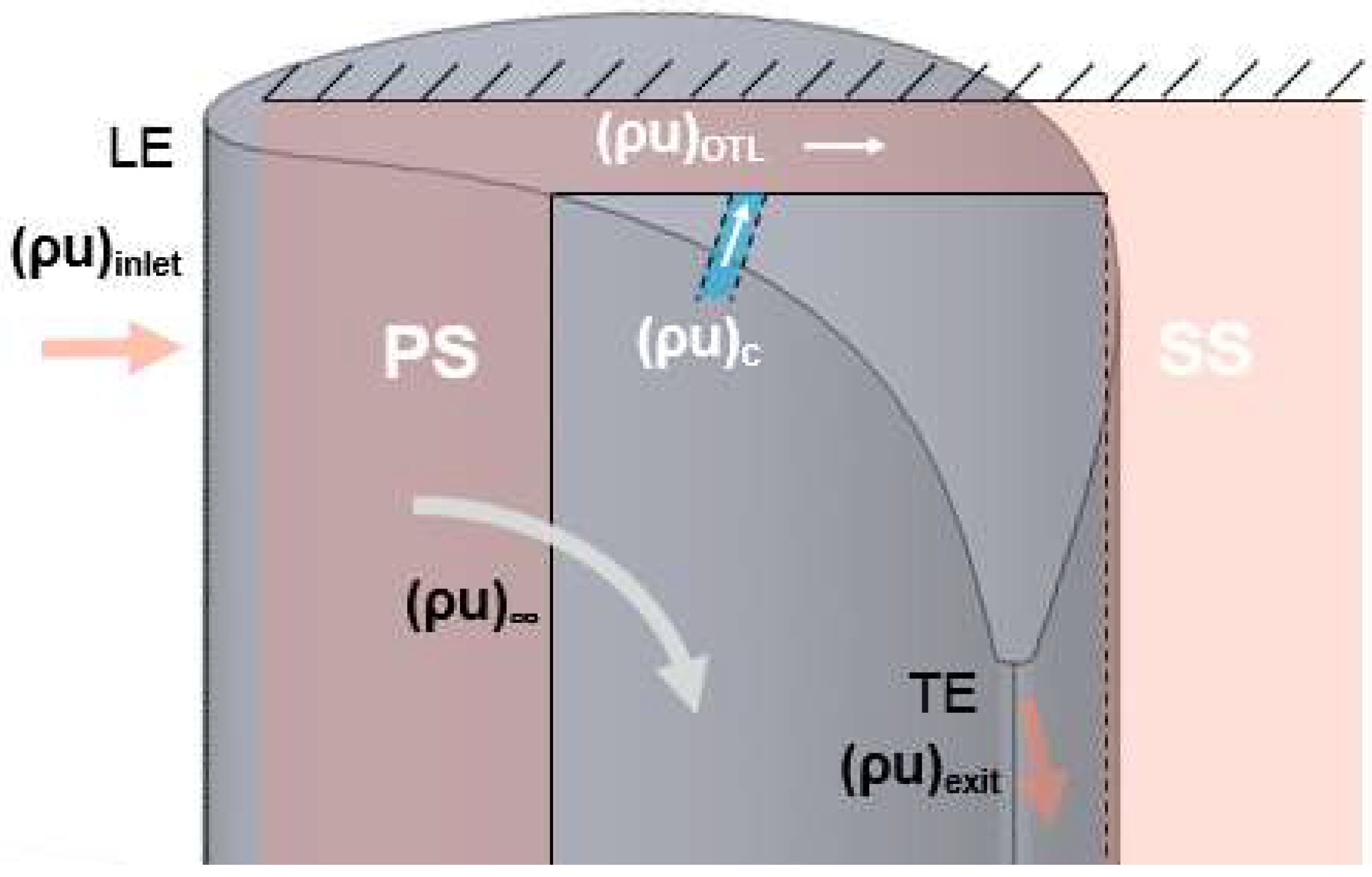
Table 1.
Summary of cooling data on flat tips.
| Reference | Technique | Hole Number | Tip Clearance | Inject Location | M | Eta | HTC | NHFR | Note |
|---|---|---|---|---|---|---|---|---|---|
| Kwak 2002 [49] | Liquid crystal | 13 | 1.50% | Camber | 2 | 0.056 | * | ||
| 26 | 1.50% | Camber + PS_near tip | 2 | 0.069 | 534 | * | |||
| Acharya 2002 [37] | CFD | 8 | 1.0% | Tip near PS | 1.00 | 0.251 | * | ||
| 8 | 1.5% | Tip near PS | 1.00 | 0.311 | 876 | * | |||
| 8 | 2.5% | Tip near PS | 1.00 | 0.303 | * | ||||
| Christophel 2003 [38] | IR | 13 | 0.5% | LE(purge) + PS near tip | 0.58% | 0.618 | 1.10 | EDM holes | |
| 13 | 0.5% | LE(purge) + PS near tip | 0.68% | 0.699 | EDM holes | ||||
| 13 | 0.5% | LE(purge) + PS near tip | 1.00% | 0.679 | 1.28 | EDM holes | |||
| 13 | 1.6% | LE(purge) + PS near tip | 0.58% | 0.268 | 0.40 | EDM holes | |||
| 13 | 1.6% | LE(purge) + PS near tip | 0.68% | 0.299 | EDM holes | ||||
| 13 | 1.6% | LE(purge) + PS near tip | 1.00% | 0.498 | 0.85 | EDM holes | |||
| 13 | 0.5% | LE(purge) + PS near tip | 0.47% | 0.599 | Laser holes | ||||
| 13 | 0.5% | LE(purge) + PS near tip | 0.58% | 0.597 | 1.10 | Laser holes | |||
| 13 | 0.5% | LE(purge) + PS near tip | 0.68% | 0.649 | Laser holes | ||||
| 13 | 0.5% | LE(purge) + PS near tip | 1.00% | 0.708 | 1.51 | Laser holes | |||
| 13 | 1.6% | LE(purge) + PS near tip | 0.47% | 0.290 | Laser holes | ||||
| 13 | 1.6% | LE(purge) + PS near tip | 0.58% | 0.321 | 0.49 | Laser holes | |||
| 13 | 1.6% | LE(purge) + PS near tip | 0.68% | 0.349 | Laser holes | ||||
| 13 | 1.6% | LE(purge) + PS near tip | 1.00% | 0.487 | 0.88 | Laser holes | |||
| Nasir 2004 [43] | Liquid crystal | 5 | 1.0% | Camber | 1 | 0.045 | 620 | * | |
| 5 | 1.0% | Camber | 2 | 0.060 | 562 | * | |||
| 5 | 1.0% | Camber | 3 | 0.043 | 526 | * | |||
| 12 | 1.0% | Camber + PS near tip | 1 | 0.107 | 524 | * | |||
| 12 | 1.0% | Camber + PS near tip | 2 | 0.094 | 431 | * | |||
| 12 | 1.0% | Camber + PS near tip | 3 | 0.237 | 708 | * | |||
| 7 | 1.0% | PS near tip | 1 | 0.058 | 621 | * | |||
| 7 | 1.0% | PS near tip | 2 | 0.030 | 500 | * | |||
| 7 | 1.0% | PS near tip | 3 | 0.051 | 575 | * | |||
| Ahn 2005 [44] | PSP | 7 | 1.00% | Camber | 0.5 | 0.019 | |||
| 7 | 1.00% | Camber | 1 | 0.023 | |||||
| 7 | 1.00% | Camber | 2 | 0.022 | |||||
| 7 | 1.50% | Camber | 0.5 | 0.013 | |||||
| 7 | 1.50% | Camber | 1 | 0.021 | |||||
| 7 | 1.50% | Camber | 2 | 0.022 | |||||
| 7 | 2.50% | Camber | 0.5 | 0.006 | |||||
| 7 | 2.50% | Camber | 1 | 0.011 | |||||
| 7 | 2.50% | Camber | 2 | 0.026 | |||||
| 7 | 1.00% | PS near tip | 0.5 | 0.005 | |||||
| 7 | 1.00% | PS near tip | 1 | 0.050 | |||||
| 7 | 1.00% | PS near tip | 2 | 0.057 | |||||
| 7 | 1.50% | PS near tip | 0.5 | 0.004 | |||||
| 7 | 1.50% | PS near tip | 1 | 0.036 | |||||
| 7 | 1.50% | PS near tip | 2 | 0.031 | |||||
| 7 | 2.50% | PS near tip | 0.5 | 0.003 | |||||
| 7 | 2.50% | PS near tip | 1 | 0.020 | |||||
| 7 | 2.50% | PS near tip | 2 | 0.027 | |||||
| 14 | 1.00% | Camber + PS near tip | 0.5 | 0.012 | |||||
| 14 | 1.00% | Camber + PS near tip | 1 | 0.028 | |||||
| 14 | 1.00% | Camber + PS near tip | 2 | 0.062 | |||||
| 14 | 1.50% | Camber + PS near tip | 0.5 | 0.012 | |||||
| 14 | 1.50% | Camber + PS near tip | 1 | 0.020 | |||||
| 14 | 1.50% | Camber + PS near tip | 2 | 0.055 | |||||
| 14 | 2.50% | Camber + PS near tip | 0.5 | 0.019 | |||||
| 14 | 2.50% | Camber + PS near tip | 1 | 0.028 | |||||
| 14 | 2.50% | Camber + PS near tip | 2 | 0.050 | |||||
| Christophel 2005 [39] | IR | 2 | 0.5% | LE(purge) | 0.10% | 0.178 | 0.32 | purge holes | |
| 2 | 0.5% | LE(purge) | 0.19% | 0.382 | 0.71 | purge holes | |||
| 2 | 0.5% | LE(purge) | 0.29% | 0.431 | 0.86 | purge holes | |||
| 2 | 0.5% | LE(purge) | 0.38% | 0.448 | 1.16 | purge holes | |||
| 2 | 1.6% | LE(purge) | 0.10% | 0.074 | 0.11 | purge holes | |||
| 2 | 1.6% | LE(purge) | 0.19% | 0.099 | 0.08 | purge holes | |||
| 2 | 1.6% | LE(purge) | 0.29% | 0.198 | 0.26 | purge holes | |||
| 2 | 1.6% | LE(purge) | 0.38% | 0.300 | 0.51 | purge holes | |||
| Newton 2009 [45] | Liquid crystal | 11 | 4.4% C | Camber | 0.8 | 0.122 | 87 | 0.23 | * |
| 11 | 2.2% C | Tip near PS | 0.58 | 0.166 | 98 | 0.37 | * | ||
| 11 | 2.2% C | Tip near PS | 0.74 | 0.159 | 90 | 0.37 | * | ||
| 11 | 2.2% C | Tip near PS | 0.99 | 0.140 | 100 | 0.28 | * | ||
| Rezasoltani 2015 [9] | PSP | 7 | 1.50% | Camber | 1.25 | 0.035 | 2000 rpm | ||
| 8 | 1.50% | PS near tip | 1.25 | 0.089 | 2000 rpm | ||||
| 7 | 1.50% | Camber | 1.25 | 0.054 | 2550 rpm | ||||
| 8 | 1.50% | PS near tip | 1.25 | 0.059 | 2550 rpm | ||||
| 7 | 1.50% | Camber | 0.75 | 0.047 | 3000 rpm | ||||
| 7 | 1.50% | Camber | 1.25 | 0.650 | 3000 rpm | ||||
| 7 | 1.50% | Camber | 1.75 | 0.069 | 3000 rpm | ||||
| 8 | 1.50% | PS near tip | 0.75 | 0.024 | 3000 rpm | ||||
| 8 | 1.50% | PS near tip | 1.25 | 0.310 | 3000 rpm | ||||
| 8 | 1.50% | PS near tip | 1.75 | 0.040 | 3000 rpm | ||||
| Yang 2006 [50] | CFD | 7 | 1.50% | camber | 0.50 | 0.013 | * | ||
| 7 | 1.50% | camber | 1.00 | 0.016 | * | ||||
| 7 | 1.50% | camber | 2.00 | 0.002 | * | ||||
| 7 | 1.50% | Tip near PS | 0.50 | 0.045 | * | ||||
| 7 | 1.50% | Tip near PS | 1.00 | 0.071 | * | ||||
| 7 | 1.50% | Tip near PS | 2.00 | 0.041 | * | ||||
| 10 | 1.50% | camber + tip near PS | 0.25 | 0.028 | * | ||||
| 10 | 1.50% | camber + tip near PS | 0.50 | 0.056 | * | ||||
| 10 | 1.50% | camber + tip near PS | 1.00 | 0.070 | * | ||||
| Hohlfeld 2005 [42] | CFD | 2 | 0.54% | Tip near LE(purge) | 0.19% | 0.259 | |||
| 2 | 0.54% | Tip near LE(purge) | 0.29% | 0.363 | |||||
| 2 | 1.63% | Tip near LE(purge) | 0.05% | 0.057 | |||||
| 2 | 1.63% | Tip near LE(purge) | 0.10% | 0.045 | |||||
| 2 | 1.63% | Tip near LE(purge) | 0.19% | 0.019 | |||||
| 2 | 1.63% | Tip near LE(purge) | 0.29% | 0.025 | |||||
| 2 | 1.63% | Tip near LE(purge) | 0.38% | 0.046 |
Note: abbreviations in table: Eta—adiabatic cooling effectiveness; HTC—convective heat transfer coefficient; M—blowing ratio; PR—pressure ratio; PS—pressure side; SS—suction side; LE—leading edge; camber—along camber line; IR—infrared thermal graphical technique; NHFR—net heat flux reduction. * indicates the average Eta and HTC values are estimated based on the color contour from the publication. Tip clearance normalized by blade height in percentage, except in the report by Newton et al. [45] where tip clearance is normalized by blade chord. Coolant flow rate if in percentage meaning normalized by passage flow rate, otherwise normalized in blowing ratio.
Table 2.
Summary of cooling data on squealer tips.
| Reference | Technique | Hole Number | Tip Clearance | Cavity Depth | M | Inject Location | Eta | HTC | Note |
|---|---|---|---|---|---|---|---|---|---|
| Acharya 2002 [37] | CFD | 7 | 1.0% | 3.77% | 1.00 | Tip near PS | 0.234 | * | |
| 7 | 1.5% | 3.77% | 1.00 | Tip near PS | 0.171 | * | |||
| 7 | 2.5% | 3.77% | 1.00 | Tip near PS | 0.141 | * | |||
| 7 | 2.5% | 3.77% | 1.50 | Tip near PS | 0.228 | * | |||
| Kwak 2002 [49] | Liquid crystal | 13 | 1.50% | 4.22% | 1 | Camber | 0.072 | 416.786 | * |
| 13 | 1.50% | 4.22% | 2 | Camber | 0.083 | 397.001 | * | ||
| 26 | 1.50% | 4.22% | 1 | Camber + PS_near tip | 0.103 | 400.591 | * | ||
| 26 | 1.50% | 4.22% | 2 | Camber + PS_near tip | 0.113 | 375.995 | * | ||
| Tong 2014 [60] | CFD | 10 | 1.00% | 1.90% | PR = 3.57 | camber | 0.157 | 4644.18 | |
| 10 | 1.00% | 2.50% | PR = 3.65 | camber | 0.201 | 4552.06 | |||
| 10 | 1.00% | 3.10% | PR = 3.45 | camber | 0.138 | 4466.4 | |||
| Nasir 2004 [43] | Liquid crystal | 5 | 1.0% | 4.22% | 1 | Camber | 0.055 | 525.314 | * |
| 5 | 1.0% | 4.22% | 2 | Camber | 0.082 | 460.092 | * | ||
| 5 | 1.0% | 4.22% | 3 | Camber | 0.044 | 487.702 | * | ||
| 12 | 1.0% | 4.22% | 1 | Camber + PS near tip | 0.058 | 496.088 | * | ||
| 12 | 1.0% | 4.22% | 2 | Camber + PS near tip | 0.056 | 466.922 | * | ||
| 12 | 1.0% | 4.22% | 3 | Camber + PS near tip | 0.166 | 773.907 | * | ||
| 7 | 1.0% | 4.22% | 1 | PS near tip | 0.019 | 552.362 | * | ||
| 7 | 1.0% | 4.22% | 2 | PS near tip | 0.019 | 543.478 | * | ||
| 7 | 1.0% | 4.22% | 3 | PS near tip | 0.036 | 538.185 | * | ||
| Ahn 2005 [44] | PSP | 7 | 1.00% | 4.22% | 0.5 | Camber | 0.022 | ||
| 7 | 1.00% | 4.22% | 1 | Camber | 0.025 | ||||
| 7 | 1.00% | 4.22% | 2 | Camber | 0.051 | ||||
| 7 | 1.50% | 4.22% | 0.5 | Camber | 0.019 | ||||
| 7 | 1.50% | 4.22% | 1 | Camber | 0.028 | ||||
| 7 | 1.50% | 4.22% | 2 | Camber | 0.051 | ||||
| 7 | 2.50% | 4.22% | 0.5 | Camber | 0.023 | ||||
| 7 | 2.50% | 4.22% | 1 | Camber | 0.036 | ||||
| 7 | 2.50% | 4.22% | 2 | Camber | 0.039 | ||||
| 7 | 1.00% | 4.22% | 0.5 | PS near tip | 0.021 | ||||
| 7 | 1.00% | 4.22% | 1 | PS near tip | 0.026 | ||||
| 7 | 1.00% | 4.22% | 2 | PS near tip | 0.035 | ||||
| 7 | 1.50% | 4.22% | 0.5 | PS near tip | 0.020 | ||||
| 7 | 1.50% | 4.22% | 1 | PS near tip | 0.020 | ||||
| 7 | 1.50% | 4.22% | 2 | PS near tip | 0.021 | ||||
| 7 | 2.50% | 4.22% | 0.5 | PS near tip | 0.019 | ||||
| 7 | 2.50% | 4.22% | 1 | PS near tip | 0.021 | ||||
| 7 | 2.50% | 4.22% | 2 | PS near tip | 0.024 | ||||
| 14 | 1.00% | 4.22% | 0.5 | Camber + PS near tip | 0.033 | ||||
| 14 | 1.00% | 4.22% | 1 | Camber + PS near tip | 0.042 | ||||
| 14 | 1.00% | 4.22% | 2 | Camber + PS near tip | 0.060 | ||||
| 14 | 1.50% | 4.22% | 0.5 | Camber + PS near tip | 0.034 | ||||
| 14 | 1.50% | 4.22% | 1 | Camber + PS near tip | 0.048 | ||||
| 14 | 1.50% | 4.22% | 2 | Camber + PS near tip | 0.060 | ||||
| 14 | 2.50% | 4.22% | 0.5 | Camber + PS near tip | 0.039 | ||||
| 14 | 2.50% | 4.22% | 1 | Camber + PS near tip | 0.048 | ||||
| 14 | 2.50% | 4.22% | 2 | Camber + PS near tip | 0.066 | ||||
| Mhetras 2006 [51] | PSP | 9 | 1.50% | 2.10% | 0.50 | PS near tip | 0.015 | ||
| 9 | 1.50% | 2.10% | 1.00 | PS near tip | 0.027 | ||||
| 9 | 1.50% | 2.10% | 1.50 | PS near tip | 0.032 | ||||
| 9 | 1.50% | 2.10% | 2.00 | PS near tip | 0.038 | ||||
| 10 | 1.50% | 2.10% | 0.50 | Camber + tip near SS | 0.109 | ||||
| 10 | 1.50% | 2.10% | 1.00 | Camber + tip near SS | 0.147 | ||||
| 10 | 1.50% | 2.10% | 1.50 | Camber + tip near SS | 0.148 | ||||
| 10 | 1.50% | 2.10% | 2.00 | Camber + tip near SS | 0.153 | ||||
| 9 | 1.50% | 4.20% | 0.50 | PS near tip | 0.023 | ||||
| 9 | 1.50% | 4.20% | 1.00 | PS near tip | 0.027 | ||||
| 9 | 1.50% | 4.20% | 1.50 | PS near tip | 0.032 | ||||
| 9 | 1.50% | 4.20% | 2.00 | PS near tip | 0.047 | ||||
| 10 | 1.50% | 4.20% | 0.50 | Camber + tip near SS | 0.105 | ||||
| 10 | 1.50% | 4.20% | 1.00 | Camber + tip near SS | 0.133 | ||||
| 10 | 1.50% | 4.20% | 1.50 | Camber + tip near SS | 0.151 | ||||
| 10 | 1.50% | 4.20% | 2.00 | Camber + tip near SS | 0.163 | ||||
| Yang 2006 [50] | CFD | 7 | 1.50% | 3.77% | 0.50 | camber | 0.052 | ||
| 7 | 1.50% | 3.77% | 1.00 | camber | 0.075 | ||||
| 7 | 1.50% | 3.77% | 2.00 | camber | 0.045 | ||||
| 7 | 1.50% | 3.77% | 0.50 | camber + tip near LE | 0.127 | ||||
| 7 | 1.50% | 3.77% | 1.00 | camber + tip near LE | 0.173 | ||||
| 7 | 1.50% | 3.77% | 2.00 | camber + tip near LE | 0.190 | ||||
| 13 | 1.50% | 3.77% | 0.25 | Camber + tip near SS | 0.108 | ||||
| 13 | 1.50% | 3.77% | 0.50 | Camber + tip near SS | 0.167 | ||||
| 13 | 1.50% | 3.77% | 1.00 | Camber + tip near SS | 0.241 | ||||
| Gao 2009 [55] | PSP | 19 | 1.50% | 2.10% | 0.50 | Camber + tip near SS + PS near tip | 0.100 | Incidence −5 deg | |
| 19 | 1.50% | 2.10% | 1.00 | Camber + tip near SS + PS near tip | 0.135 | Incidence −5 deg | |||
| 19 | 1.50% | 2.10% | 1.50 | Camber + tip near SS + PS near tip | 0.132 | Incidence −5 deg | |||
| 19 | 1.50% | 2.10% | 2.00 | Camber + tip near SS + PS near tip | 0.140 | Incidence −5 deg | |||
| 19 | 1.50% | 2.10% | 0.50 | Camber + tip near SS + PS near tip | 0.115 | Incidence 0 deg | |||
| 19 | 1.50% | 2.10% | 1.00 | Camber + tip near SS + PS near tip | 0.135 | Incidence 0 deg | |||
| 19 | 1.50% | 2.10% | 1.50 | Camber + tip near SS + PS near tip | 0.132 | Incidence 0 deg | |||
| 19 | 1.50% | 2.10% | 2.00 | Camber + tip near SS + PS near tip | 0.136 | Incidence 0 deg | |||
| 19 | 1.50% | 2.10% | 0.50 | Camber + tip near SS + PS near tip | 0.110 | Incidence 5 deg | |||
| 19 | 1.50% | 2.10% | 1.00 | Camber + tip near SS + PS near tip | 0.150 | Incidence 5 deg | |||
| 19 | 1.50% | 2.10% | 1.50 | Camber + tip near SS + PS near tip | 0.171 | Incidence 5 deg | |||
| 19 | 1.50% | 2.10% | 2.00 | Camber + tip near SS + PS near tip | 0.171 | Incidence 5 deg | |||
| Nazary 2009 [56] | Liquid crystal | 33 | 0.87% | 1.81% | PR = 1.19 | (LE + PS + SS) near tip | 0.021 | * | |
| 33 | 0.87% | 1.81% | PR = 1.31 | (LE + PS + SS) near tip | 0.031 | * | |||
| 33 | 0.87% | 1.81% | PR = 1.48 | (LE + PS + SS) near tip | 0.043 | * | |||
| 33 | 0.87% | 1.81% | PR = 1.57 | (LE + PS + SS) near tip | 0.054 | * | |||
| 33 | 1.59% | 1.81% | PR = 1.17 | (LE + PS + SS) near tip | 0.008 | * | |||
| 33 | 1.59% | 1.81% | PR = 1.26 | (LE + PS + SS) near tip | 0.028 | * | |||
| 33 | 1.59% | 1.81% | PR = 1.39 | (LE + PS + SS) near tip | 0.028 | * | |||
| 33 | 1.59% | 1.81% | PR = 1.58 | (LE + PS + SS) near tip | 0.030 | * | |||
| 33 | 2.32% | 1.81% | PR = 1.16 | (LE + PS + SS) near tip | 0.016 | * | |||
| 33 | 2.32% | 1.81% | PR = 1.24 | (LE + PS + SS) near tip | 0.018 | * | |||
| 33 | 2.32% | 1.81% | PR = 1.39 | (LE + PS + SS) near tip | 0.028 | * | |||
| 33 | 2.32% | 1.81% | PR = 1.52 | (LE + PS + SS) near tip | 0.027 | * | |||
| 63 | 0.87% | 1.81% | 0.5 | (LE + PS + SS) near tip + rim hub | 0.007 | * | |||
| 63 | 0.87% | 1.81% | 1 | (LE + PS + SS) near tip + rim hub | 0.027 | * | |||
| 63 | 0.87% | 1.81% | 1.5 | (LE + PS + SS) near tip + rim hub | 0.042 | * | |||
| 63 | 0.87% | 1.81% | 2 | (LE + PS + SS) near tip + rim hub | 0.068 | * | |||
| 63 | 1.59% | 1.81% | 0.5 | (LE + PS + SS) near tip + rim hub | 0.011 | * | |||
| 63 | 1.59% | 1.81% | 1 | (LE + PS + SS) near tip + rim hub | 0.030 | * | |||
| 63 | 1.59% | 1.81% | 1.5 | (LE + PS + SS) near tip + rim hub | 0.046 | * | |||
| 63 | 1.59% | 1.81% | 2 | (LE + PS + SS) near tip + rim hub | 0.069 | * | |||
| 63 | 2.32% | 1.81% | 0.5 | (LE + PS + SS) near tip + rim hub | 0.017 | * | |||
| 63 | 2.32% | 1.81% | 1 | (LE + PS + SS) near tip + rim hub | 0.026 | * | |||
| 63 | 2.32% | 1.81% | 1.5 | (LE + PS + SS) near tip + rim hub | 0.053 | * | |||
| 63 | 2.32% | 1.81% | 2 | (LE + PS + SS) near tip + rim hub | 0.065 | * | |||
| Rezasoltani 2015 [9] | PSP | 7 | 1.50% | 3.15% | 1.25 | Camber | 0.097 | 2000 rpm | |
| 8 | 1.50% | 3.15% | 1.25 | PS near tip | 0.054 | 2000 rpm | |||
| 7 | 1.50% | 3.15% | 1.25 | Camber | 0.060 | 2550 rpm | |||
| 8 | 1.50% | 3.15% | 1.25 | PS near tip | 0.040 | 2550 rpm | |||
| 7 | 1.50% | 3.15% | 0.75 | Camber | 0.052 | 3000 rpm | |||
| 7 | 1.50% | 3.15% | 1.25 | Camber | 0.052 | 3000 rpm | |||
| 7 | 1.50% | 3.15% | 1.75 | Camber | 0.068 | 3000 rpm | |||
| 8 | 1.50% | 3.15% | 0.75 | PS near tip | 0.018 | 3000 rpm | |||
| 8 | 1.50% | 3.15% | 1.25 | PS near tip | 0.020 | 3000 rpm | |||
| 8 | 1.50% | 3.15% | 1.75 | PS near tip | 0.022 | 3000 rpm | |||
| Tamunobere 2016 [63] | Liquid crystal | 2 | 1.70% | NA | 1.5 | camber | 0.028 | 206.267 | * |
| 2 | 1.70% | NA | 3 | camber | 0.058 | 234.096 | * | ||
| 6 | 1.70% | NA | 1.5 | PS near tip | 0.021 | 220.824 | * | ||
| 6 | 1.70% | NA | 3 | PS near tip | 0.047 | 207.867 | * | ||
| 8 | 1.70% | NA | 1 | camber + PS near tip | 0.029 | 216.639 | * | ||
| 8 | 1.70% | NA | 1.5 | camber + PS near tip | 0.043 | 220.103 | * | ||
| 8 | 1.70% | NA | 2 | camber + PS near tip | 0.059 | 237.537 | * | ||
| 8 | 1.70% | NA | 3 | camber + PS near tip | 0.072 | 233.535 | * | ||
| 8 | 1.70% | NA | 4 | camber + PS near tip | 0.080 | 250.733 | * | ||
| Ma 2016 [58] | IR | 9 | 1.00% | NA | 0.45% | tip near PS | 0.050 | 1369.34 | * |
| 9 | 1.00% | NA | 0.45% | Camber | 0.042 | 1265.58 | * | ||
| 9 | 1.00% | NA | 0.45% | tip near SS | 0.042 | 1194.15 | * | ||
| Yan 2017 [63] | CFD | 13 | 1.00% | 4.16% | 1 | camber | 0.061 | squealer | |
| 13 | 1.00% | 4.16% | 1 | camber | 0.056 | SS rim only | |||
| 13 | 1.00% | 4.16% | 1 | camber | 0.076 | PS winglet | |||
| 13 | 1.50% | 4.16% | 1 | camber | 0.051 | squealer | |||
| 13 | 1.50% | 4.16% | 1 | camber | 0.061 | SS rim only | |||
| 13 | 1.50% | 4.16% | 1 | camber | 0.056 | PS winglet | |||
| 26 | 1.00% | 4.16% | 1 | Camber + PS near tip | 0.126 | squealer | |||
| 26 | 1.00% | 4.16% | 1 | Camber + PS near tip | 0.135 | SS rim only | |||
| 26 | 1.00% | 4.16% | 1 | Camber + PS near tip | 0.132 | PS winglet | |||
| 26 | 1.50% | 4.16% | 1 | Camber + PS near tip | 0.083 | squealer | |||
| 26 | 1.50% | 4.16% | 1 | Camber + PS near tip | 0.131 | SS rim only | |||
| 26 | 1.50% | 4.16% | 1 | Camber + PS near tip | 0.128 | PS winglet | |||
| Arisi 2015 [14] | IR | 2 | 1.00% | 1.50% | 1 | camber | 0.120 | 628.219 | Ma_exit 0.8; purge |
| 2 | 1.00% | 1.50% | 1 | camber | 0.124 | 702.173 | Ma_exit 1.0; purge |
Note: abbreviations in table: Eta—adiabatic cooling effectiveness; HTC—convective heat transfer coefficient; M—blowing ratio; PR—pressure ratio; PS—pressure side; SS—suction side; LE—leading edge; camber—along camber line; IR—infrared thermal graphical technique; * indicates the average Eta and HTC values are estimated based on the color contour from the publication; coolant flow rate if in percentage indicates normalized by passage flow rate; RP indicates pressure ratio between coolant flow and mean flow pressure; otherwise normalized in blowing ratio.
© 2018 by the authors. Licensee MDPI, Basel, Switzerland. This article is an open access article distributed under the terms and conditions of the Creative Commons Attribution (CC BY) license (http://creativecommons.org/licenses/by/4.0/).
Share and Cite
MDPI and ACS Style
Xue, S.; Ng, W.F. Turbine Blade Tip External Cooling Technologies. Aerospace 2018, 5, 90. https://doi.org/10.3390/aerospace5030090
AMA Style
Xue S, Ng WF. Turbine Blade Tip External Cooling Technologies. Aerospace. 2018; 5(3):90. https://doi.org/10.3390/aerospace5030090
Chicago/Turabian StyleXue, Song, and Wing F. Ng. 2018. "Turbine Blade Tip External Cooling Technologies" Aerospace 5, no. 3: 90. https://doi.org/10.3390/aerospace5030090
Note that from the first issue of 2016, this journal uses article numbers instead of page numbers. See further details here.