Synthesis, Analysis, and Design of a Novel Mechanism for the Trailing Edge of a Morphing Wing


Department of Aerospace Engineering, METU, Ankara 06800, Turkey
*
Author to whom correspondence should be addressed.
Aerospace 2018, 5(4), 127; https://doi.org/10.3390/aerospace5040127
Submission received: 9 November 2018
/
Revised: 5 December 2018
/
Accepted: 7 December 2018
/
Published: 11 December 2018
(This article belongs to the Special Issue 8th EASN-CEAS Workshop on Manufacturing for Growth and Innovation)
Abstract
:In the design and analysis of morphing wings, several sciences need to be integrated. This article tries to answer the question, “What is the most appropriate actuation mechanism to morph the wing profile?” by introducing the synthesis, analysis, and design of a novel scissor-structural mechanism (SSM) for the trailing edge of a morphing wing. The SSM, which is deployable, is created via a combination of various scissor-like elements (SLEs). In order to provide mobility requirements, a four-bar linkage (FBL) is assembled with the proposed SSM. The SSM is designed with a novel kinematic synthesis concept, so it follows the airfoil camber with minimum design error. In this concept, assuming a fully-compliant wing skin, various types of SLEs are assembled together, and emergent SSM provide the desired airfoil geometries. In order to provide the required aerodynamic efficiency of newly-created airfoil geometries and obtain pressure distribution over the airfoil, two-dimensional (2D) aerodynamic analyses have been conducted. The analyses show similar aerodynamic behavior with the desired NACA airfoils. By assigning the approximate link masses and mass centers, the dynamic force analysis of the mechanism has also been performed, and the required torque to drive the newly-developed SSM is estimated as feasible.
1. Introduction
Since the early ages, nature has been the main source of inspiration and imagination for humankind due to its grace, complexity, beauty, and mystery in order to solve complex engineering problems. For instance, the flight action varies according to different atmospheric conditions and desired flight paths as hovering, gliding, soaring, and flapping, which are not accomplished by aircraft, but actually by birds by changing their wings rapidly into various forms [1,2].
Researchers had a common sense that aircraft can achieve greater efficiency and productivity if they act like birds. In other words, the analogy with the dynamics of a bird wing requires that the morphing wings eliminate the conventional control surface effects in order to ensure that the flow remains smooth and to minimize the disruption of the surface dislocations and reduce the formation of vortices caused by lift-induced drag [3]. Because of the latest advances in materials science, actuation mechanisms, and structural and manufacturing technologies, the “morphing technology” allows aircraft to use a wide range of wing configurations in flight. First of all, a morphing wing will produce optimum aerodynamic performance over the operational envelope of an aircraft and expand its operating envelope [4,5]. Moreover, by replacing the conventional surfaces with morphing surfaces, the fight control and maneuverability can be improved [6,7]. In addition to the efficient cruise and aggressive maneuvers, the flight range will increase, which will reduce the operational costs by significant fuel savings due to the reduced drag and enhanced thrust generated [8]. Lastly, the use of morphing wings will be expected to play an important role in vibration reduction and will give the opportunity to control flutter, which will significantly improve the comfort and safety and reduce fatigue.
Studies related to the morphing wing can be classified in terms of dimensions that undergo substantial changes such as: planform alternation, airfoil adjustment, and out-of-plane transformation [9]. In the planform alternation, the aircraft wing is aimed at being altered in terms of the span change, the chord-length change, and the sweep-angle change. In the airfoil adjustment category, resizing the thickness and changing the camber-rate of the airfoil is the main purpose. In the out-of-plane transformation, the span-wise and chord-wise bending with wing twisting are intended to be applied [2,9]. It is widely known that the camber of an airfoil has a significant impact on the aerodynamic forces generated under fluid flow [10,11]. Therefore, it is believed that the most effective way to control the forces and moments that occur on aircraft wings is to change the camber-rate of the airfoil [12].
Although the study of the morphing wings requires the simultaneous application of several sciences, researchers have work in specific research areas in order to develop new technologies [13]. Hence, in this article, only the kinematic synthesis of an actuation mechanism, which morphs the trailing edge of an aircraft wing, is extensively investigated. It is assumed that the wing has a compliant skin; therefore, it can undergo any desired displacement.
Starting from the first controlled flight by the Wright brothers, several researchers have proposed the camber/decamber alteration systems for the aircraft wing and control surfaces [14,15,16,17,18,19]. More recently in 1999, Monner et al. [20] proposed a flexible flap system for an adaptive wing, which varies both in a chordwise and a spanwise differential camber during flight. In 2004, Bartley-Cho et al. [21] addressed the development of smart technologies and the demonstration of the high-rate actuation of hingeless, spanwise, and chordwise deformable control surfaces using a smart material-based actuator in order to improve the aerodynamic performance of a military aircraft. In 2005, Campanile and Anders [22] presented the “belt-rib concept” for variable-camber airfoils, which was developed at DLR (German Aerospace Centre) in the framework of the Adaptive Wing project (in German: Adaptiver Flügel—ADIF). In that concept, instead of using articulated mechanisms, the belt-rib concept is implanted, which can be actuated by piezoceramics or shape memory alloys. In 2009, Marques et al. [23] suggested a variable camber flap concept, which resulted in significant drag reduction and energy savings compared to conventional flaps. In 2011, Vos and Barrett [24] used a pressure-adaptive honeycomb in the design of the trailing edge of a morphing wing. In 2016, Takahashi et al. [25] developed a variable-camber morphing wing composed of corrugated structures. In 2016, Pecora et al. [26] presented a novel wing flap, which enables bi-modal airfoil camber morphing. In 2017, Wu et al. [27] presented a morphing carbon fiber composite airfoil concept with an active trailing edge, which is enabled by an innovative structure driven by an electrical actuation system that uses linear ultrasonic motors (LUSM) with compliant runners.
One of the most effective methods of meeting the large-scale rapid change needs is to use deployable structures often called “structural mechanisms” [28], since they behave as mechanisms during the conversion process and resist loads when they are fixed [29,30]. The deployable structures have been widely surveyed and utilized in ordinary mechanical engineering [31], for example in complex space missions [32], small-scale structural applications [33], covering of swimming pools [34], bridge systems [35], and aerospace applications [36].
The most popular deployable structure is the scissor-structural mechanism (SSM), which is based on a scissor-like element (SLE), because they show effective performance by providing significant volume expansion, easy, and quick assembling/disassembling, requiring minimal damage to structural components during working [37]. With those advantages, for morphing wings, which require a large alteration of the skin and the body, the usage of SSMs can be a powerful solution.
Therefore, in this article, the synthesis, analysis, and design of SSMs, which consist of several types of SLEs for the trailing edge of a morphing wing, have been attempted, and it is shown that the SSMs reduce the actuation mechanisms’ complexity, produce good aerodynamic performance and require feasible torque.
2. Materials and Methods
This section details the theory behind the newly-developed actuation mechanism for the morphing of the trailing edge.
2.1. Scissor-Structural Mechanisms
2.1.1. Terms and Definitions
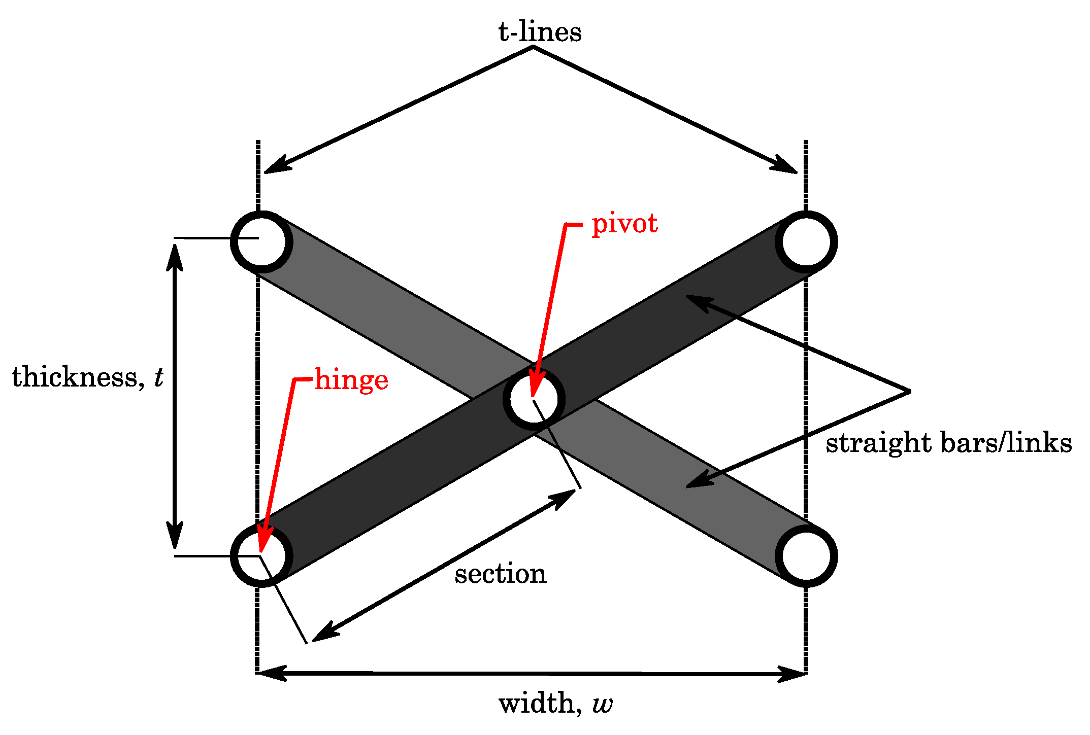
An SLE, also known as a pantograph or scissor-hinge unit, is a special type of kinematic element that is formed by two or more bars hinged together by a kinematic pair, often a revolute joint (“scissor-hinge”) [38].
In Figure 1, the most basic form of an SLE is shown. In that, two straight bars are assembled to each other with a revolute joint. This location can be called the “pivot”. In the same figure, end nodes, where an SLE can be assembled to another one, are shown as “hinge”. The portion of a straight bar from the pivot to the hinges is called a “section”. SLEs are distinguished by imaginary lines that go through the hinge locations, which are called “t-lines”.
2.1.2. Typology of Scissor-Like Elements
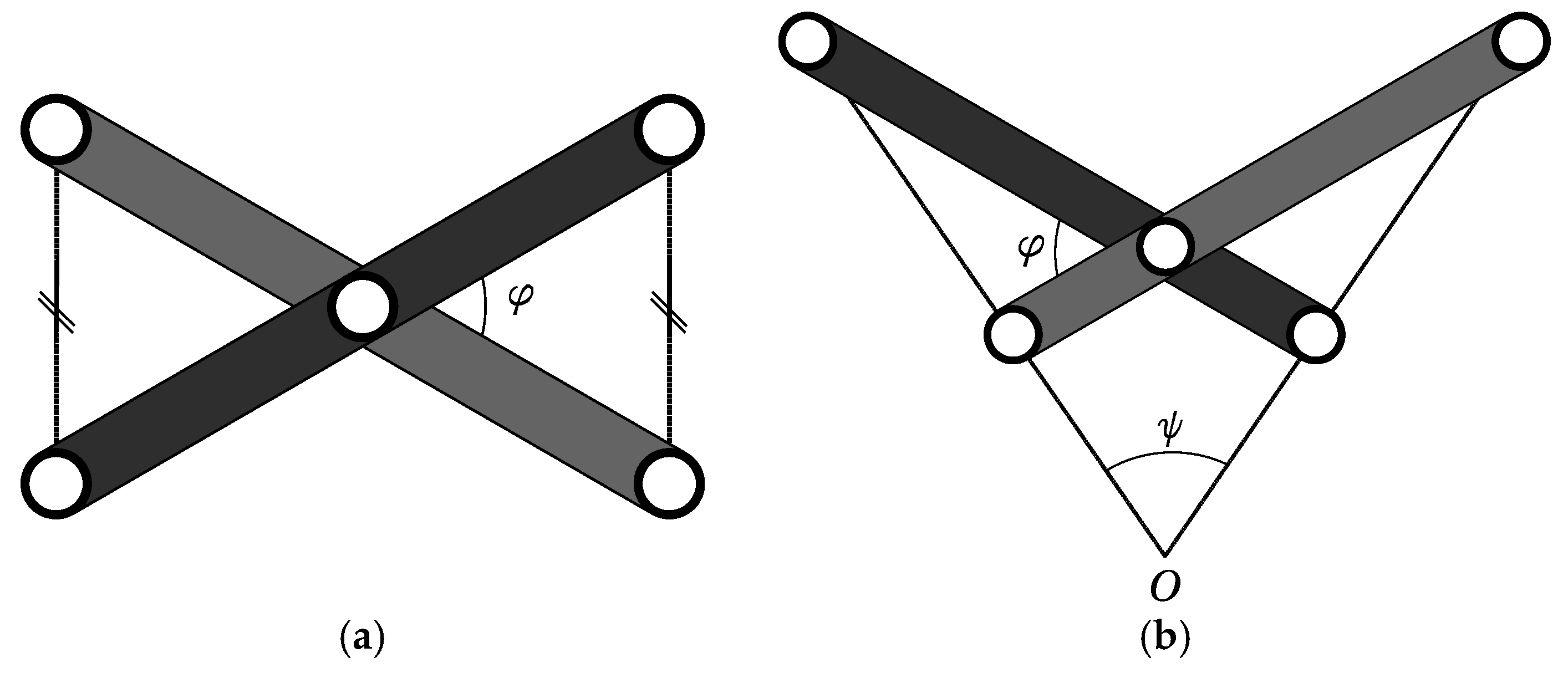
SLEs have imaginary lines that go through the joint locations where an SLE can be assembled to another one (i.e., hinges) [39]. Calling those imaginary lines “t-lines”, the group of “translational SLEs” covers the elements for which t-lines remain parallel throughout the deployment process. If the t-lines do not remain parallel throughout the deployment process, then this type of SLE is called “polar SLEs” or “curvilinear SLEs”.
The difference between translational and polar SLEs can be revealed by a single quantity, which is the difference of the section ratios of bars from the SLEs. For example, let and be the lengths of the straight bars where and determine the eccentricity of the hinge location. If , the SLE becomes a translational SLE; whereas, if , the SLE becomes a polar SLE. Figure 2 illustrates both translational and polar SLEs.
The common property of SLEs is the inverse-proportion of the thickness and the width. It is clearly seen that, by changing the type of SLE, such an inverse relation can take a complex form, which is used to stretch/shrink/bend any geometry in any direction. This relation can be brought out by defining a “foldability vector”, which connects the midpoints of consecutive thicknesses. The detailed derivation of the foldability vector for each type of SLE can be found in [40,41].
2.2. Kinematic Analysis of Scissor-Structural Mechanisms
In order to find out the kinematic capability of the designed mechanism where the resulting velocities and accelerations will be used in order to determine the inertial forces and compute the required torque to drive the mechanism, the kinematic analysis of a mechanism is required.
2.2.1. Mobility of Scissor-Structural Mechanisms
The mobility of an SSM can be defined as the number of input parameters (prime movers or actuators) that must be independently controlled to bring the mechanism into a desired position. It is also called as the degree-of-freedom (DOF) of a mechanism [42]. It is possible to calculate the mobility of the mechanism by directly counting the number of links and joints considering the types of mechanism, links, and joints through Chebyshev–Grübler–Kutzbach’s formula. The Chebyshev–Grübler–Kutzbach’s criterion is given as [43]:
In Equation (1), represents the space in which the mechanism works. for planar and spherical mechanisms, while for spatial mechanisms. is the DOF of the mechanism, the total number of links, the total number of joints, and the independent DOF of the ith joint.
For the proposed planar SSM, which consists of translational or polar SLEs of any kind, , mobility can be calculated as: . If one of the fixed joints is set free, then mobility becomes .
According to these results, the proposed SSM cannot move (behaves as a structure) or needs two actuators to deploy; therefore, in order to obtain a single-DOF mechanism, one needs an additional input linkage system. Hence, an additional planar four-bar linkage (FBL), which was developed in [44], is assumed to be attached to manipulate the whole planar SSM.
2.2.2. Position Analysis of Scissor-Structural Mechanisms
Figure 3 represents the geometric representation of a generic planar SSM. In Figure 3, and are two straight bars that form the jth SLE of the SSM. , and , represent section lengths, and and represent the orientations about the global coordinates of those straight bars, respectively. When another SLE is attached to the jth SLE and letting the SLE, there occurs a closed-loop , which is a “quadrilateral”. This closed-loop can be expressed in complex notation as:
If the orientation angles of the SLE ( and ) are known, Equation (2) can be solved. Assuming angle varies, then multiplying both sides of Equation (2) with gives an equation in terms of , and :
In Equation (3), angle can also be eliminated by using trigonometric identities. Hence, the resulting equation takes the form of the well-known Freudenstein equation when Euler’s identity is applied:
where the Freudenstein parameters (,,) are:
Equation (4) gives an implicit relation between the position variables and . This equation can be solved by applying half-tangent representation of the sine and cosine function in terms of unknown , which gives a quadratic equation in terms of .
Since from the designed FBL, the first orientation angles and are known, the other orientation angles, and can be calculated through Equation (4). Hence, position vectors of all joints can be written in complex form as:
The details of the theory and the extensive steps of the derivation can be found in [41].
2.2.3. Velocity and Acceleration Analysis of Scissor-Structural Mechanisms
In order to conduct a velocity and acceleration analysis, one first assumes that the angular velocity and acceleration of one of the links of the first SLE is prescribed (i.e., , ), then velocities and accelerations of the whole system can be calculated. The angular velocities and accelerations of the SSM can be determined by taking time derivatives of Equation (3) and writing the equations in matrix form [45].
Angular velocities can be determined as:
where is known as the “characteristic matrix”, is the unknown angular velocity column matrix, and is the known column matrix. The details of these matrices are given in Equations (8)–(10).
Since angular velocity is prescribed, and ; the other angular velocities, and , can be determined by solving Equation (7) for every SLE separately. Hence, the velocities of all joints can be written in complex form as:
Similarly, the angular accelerations can be determined as:
where the characteristic matrix is the same as Equation (8). is an unknown angular acceleration column matrix, and is the known column matrix, which are:
Since angular acceleration is prescribed, and ; other angular accelerations, and , can be determined by solving Equation (12) for every SLE separately. Hence, accelerations of all joints can be written in complex form as:
2.3. Aerodynamic Analysis of the Surfaces Formed by Scissor-Structural Mechanisms
In order to conduct an aerodynamic analysis for the surfaces formed by the SSM, the panel method is selected. It is widely known that the panel method provides solutions for linear, inviscid, irrotational flows around solid surfaces, which are subjected to subsonic speeds. The solution algorithm employs panels in order to construct the solid interfaces with vortices and sources inducing a velocity field around the body. The corresponding pressure distribution is calculated by using the tangential velocity components distributed over the surface, which also leads to the lift and drag forces by the integration of the pressure distribution over the airfoil contour. During the analysis, the computer program XFOIL (namely XFRL5) is utilized. Throughout the solutions performed using XFOIL, with panels assigned over the airfoil, the iteration number is limited to , which is accompanied with a root-mean-square (RMS) tolerance of for convergence. Angle-of-attack (AoA) values higher than and lower than were avoided. The detailed information about aerodynamic analysis can be found in [41,47].
2.4. Dynamic Force Analysis of Scissor-Structural Mechanisms
If inertial forces and moments are considered in the dynamic analysis of the mechanism, the analysis is called as the “dynamic force analysis”. In order to determine the dynamic characteristics of the whole SSM, deriving the equations of one generic SLE is sufficient.
In the dynamic force analysis problem, in order to determine inertial forces and moments, arbitrary locations of the mass centers should be defined. The representation of arbitrary locations of mass centers of a generic SLE is given in Figure 4.
In Figure 4, and represent the mass centers of links that construct an SLE; , and , represent the position vectors of the mass centers and the angles between the corresponding link and the mass center vector of that corresponding link, respectively.
Figure 5a shows the internal and external forces and moments on a generic SLE, while Figure 5b shows inertial forces and moments of the same element.
In order to determine the characteristic of the whole SSM, the system of equations represented in Equation (16) should be constructed and solved for every SLE separately. The equation system can be solved analytically with the information of SSMs having free ends; specifically, two hinges of the Nth SLE do not carry loads (i.e., ). Therefore, internal forces on the other hinges can be calculated by solving Equation (16) starting from the Nth SLE to the first SLE (in the opposite direction of the kinematic analysis). Dynamic force analysis can be achieved by solving Equation (16) at different time steps. The details of the theory and the extensive steps of the derivation can be found in [41,48].
where is the column matrix, which contains unmown internal forces:
Using trigonometric identities, the matrix can be constituted as:
where and .
The known column matrix can be constituted as:
In Equations (18) and (19), , , , represent vectors from the mass centers to the hinges and the pivot. These vectors and their orientations can be defined as:
After the calculation of all internal forces and moments, the required driving torque of the SSM can be determined accordingly. Equation (19) considers the internal forces and externally-applied pressure forces, as well. Hence, it is suitable for the case where the aerodynamic effects are also taken into the consideration. In Equation (19), ’s denote the internal forces, and ’s stand for the external forces due to the pressure; therefore, the same equation can also be used for the dynamic force analysis of the SSM in vacuo by simply assigning ’s equal to zero.
2.5. Synthesis and Design of Scissor-Structural Mechanisms
Any planar SSM constructed by using the proposed translational and polar SLEs can generate three different 2D curves. As can be seen from Figure 6, those three curves are assumed to pass through joint locations , , , respectively. This property of planar SSMs can be used to morph structures that are described by curves.
It is convenient to start the design with the selection of the total number of used SLEs . By segmentation, “baseline curves”, which characterize the original structure, and “target curves”, which is the morphed form of the structure, can be analyzed to find the correct number of used SLE.
With the power of the computer, the above design procedure can be expedited by perturbing the design parameters. The obtained SSMs can be compared by their errors, and the final SSM that best matches both the baseline and target curves can be selected [41,46]. Such a type of error, which originates in the design, is named “design error” and can be defined as:
where in Equation (21), is the shortest distance from the newest joint locations of SLE to the target curves and is the characteristic dimension selected to reveal the percentage error.
Since all errors are lengths, so positive , the mean error can be calculated as:
which is the only parameter to compare different candidate SSMs with each other and select the best one, which has the minimum mean design error.
In this study, the theoretical parts explained so far are written in METU-licensed MATLAB software [49]. The flowchart of the complete developed computer-routine is given in Appendix A.
3. Results
This section presents the various results of the study.
3.1. Scissor-Structural Mechanism for the Trailing Edge of a Morphing Wing
In the study, the chord length of the airfoil was taken as 0.6 m, and the rear spar of the wing was taken at of the chord length, similar to [41,50]. In this paper, the actuator, which was an FBL and was intended to drive the whole SSM, was located in the torque box of the UAV wing. The FBL was assumed to be attached to the SSM and drive the SSM from the first SLE that was the closest one to the rear spar.
In Figure 7a, the SSM with SLEs is considered. The baseline airfoil was NACA 4412, and the target airfoil was NACA 8412. In this case, mean t-line orientation angle was determined as a hundred and ten degrees, . All SLEs were chosen as the type of polar-SLE with constant Segmentation was done linearly for simplicity (the width of each SLE was equal). Then, when the anchor-link was rotated in the clockwise direction, the designed SSM generated the NACA 8412 geometry with mean design error.
As seen from Figure 7b, if the anchor-link was rotated in the counter-clockwise sense from the baseline airfoil of NACA 4412, the mechanism also added the decamber property to the aircraft wing. The same SSM with SLEs could eventually generate the NACA 2412 profile with mean design error.
This study assumed that the wing skin was composed of a fully-compliant material, which followed any prescribed motion during the morphing. Such a wing concept, which was enhanced by the SSM, required the segmentation or discretization of the wing skin in the chordwise direction. Each wing skin segment corresponded to a particular SLE and changed its position and orientation together with the movement of that SLE. Hence, each skin segment could be considered as comprised of two different portions. The hinges of SLEs were assumed to be attached to the wing skin from the rigid portion of the skin segment, whereas those rigid portions were combined together with a hyper-elastic portion. Therefore, the wing skin could be formed as a sequence of rigid and hyper-elastic portions successively.
This study only considered the development of an internal actuation mechanism. However, in order to predict the characteristic of the required surface material, displacements of the wing segments which were in between two consecutive SLEs were also considered.
Figure 8a gives the first pose of the SSM with SLEs, which stretched the wing skin or produced elongation with a magnitude of at most when it morphed the wing profile into NACA 8412; whereas, Figure 8b gives the second pose of the SSM, which stretched the wing skin with a magnitude of at most when it morphed the wing profile into NACA 2412.
SSMs can affect the wing skin by stretching or shrinking the hyper-elastic portion of the wing skin segment. In order to avoid any slack of the hyper-elastic portion, the whole wing skin should be in tension. Moreover, due to structural concerns, such extensions should be small enough. As seen from the results, if the SSM was allowed to manipulate the chord length, the designed SSM stretched the wing skin up to . Therefore, the slackness of the wing skin will be avoided by using SSMs within feasible limits, which is an advantageous property. Another result was that the designed SSM required a compliant material for the elastic portion of the wing skin, which provided a safe elongation up to . Such an extension capability corresponds to materials in the literature that are good enough for aircraft wings.
3.2. Aerodynamic Analysis of the Surfaces Formed by Scissor-Structural Mechanisms for the Trailing Edge of a Morphing Wing
Aerodynamic analyses were conducted for the designed SSMs with the package XFLR5, which is an analysis tool for airfoils, wings, and planes operating at low Reynolds numbers. XFLR5 includes XFOIL’s direct and inverse analysis capabilities with wing design and analysis capabilities based on the lifting line theory, on the vortex lattice method, and on a three-dimensional (3D) panel method [51].
Figure 9 shows the aerodynamic behavior of the surfaces formed by the SSM with SLEs when the SSM morphed the baseline wing profile into the position of NACA 8412 and NACA 2412, respectively. It can be seen that the surfaces formed by the SSM nearly show as similar performance as the NACA airfoils.
3.3. Dynamic Force Analysis of the Scissor-Structural Mechanisms for the Trailing Edge of a Morphing Wing
Dynamic force analysis of the mechanism can be performed in two conditions, which are “in in vacuo” and “under aerodynamic loading”.
First of all, one should define masses and mass centers. For that purpose, the masses of links were calculated by assuming the material of the links: aluminum with . The volumes of the links and their moment of inertias were calculated assuming that the links were those of rectangular beams with a square cross-section. Both sides of each unique element were one eighth () of the airfoil thickness. The mass centers of each element were assumed to be located at their geometric centers. By considering these parameters, the weight penalty of the mechanism brought to the wing was 138.7 g, where the weight of the aircraft is 25 (kg).
3.3.1. In Vacuo Condition
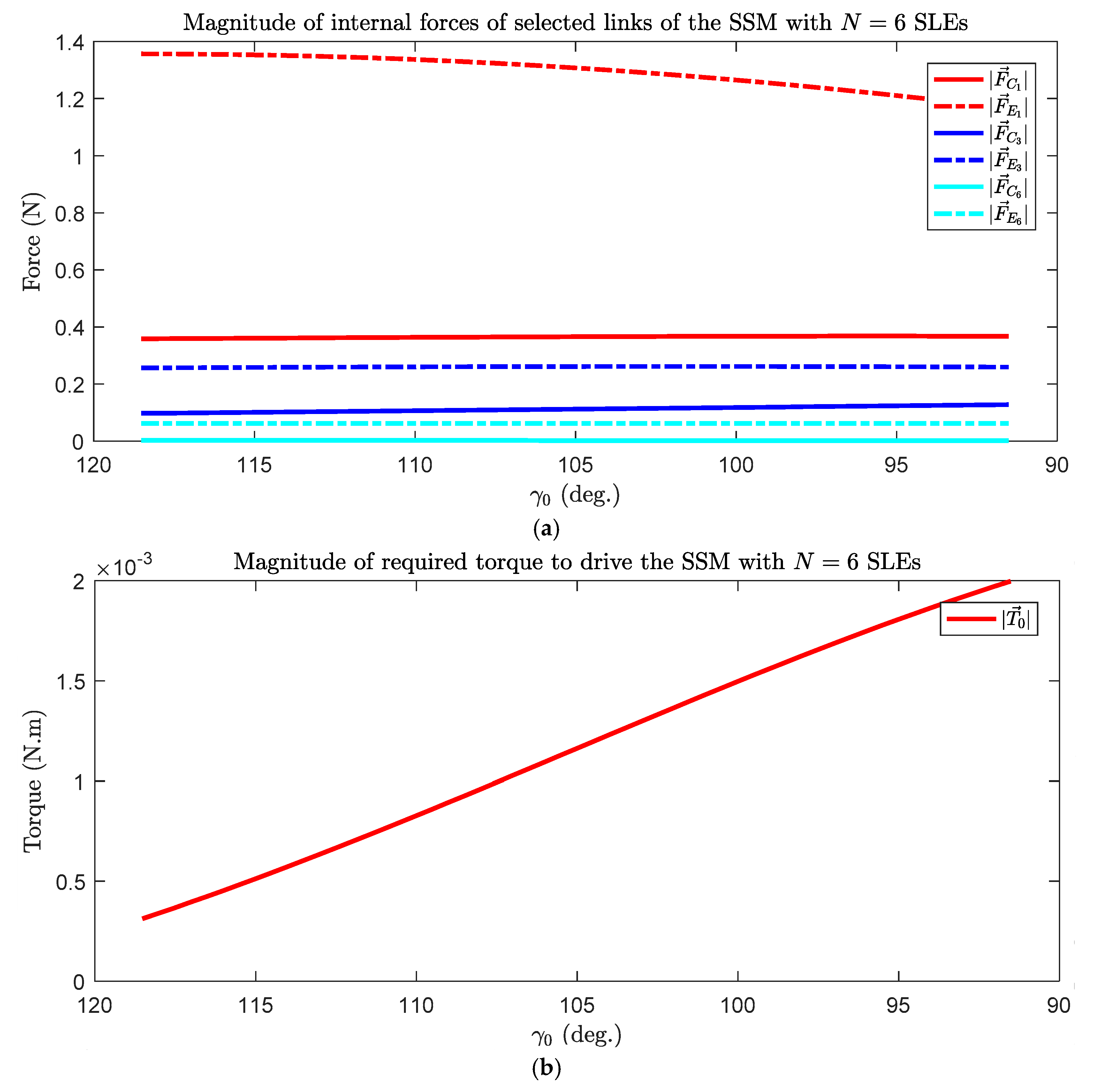
In Figure 10a, the magnitudes of internal forces of selected links (links of the first, the middle, and the last SLEs) of the SSM with SLEs while it was forming the baseline airfoil into NACA 8412 are shown.
In Figure 10b, the magnitude of required torque to drive the SSM with SLEs while it was forming the baseline airfoil into NACA 8412 is shown.
It can be seen from Figure 10 that only those links that were close to the torque application carried some internal forces due to the applied torque, whereas the other links carried almost zero internal forces. The main characteristic of such a type of deployable structure is having a stress-strain free state. The computed very low internal forces and moments are important in the verification of this fact.
Moreover, the required torque variation in in vacuo condition was below 0.002 (N·m), which is very low since the SSM is too light and aerodynamic loading is ignored. This torque value can be associated with the dynamic characteristics of the analysis, which can be neglected if the aerodynamic forces and moments are considered.
3.3.2. Under Aerodynamic Loading
The calculated pressure coefficient distribution of the surface formed by the SSM could be used to estimate the required torque to drive the SSM under aerodynamic loading. In order to convert the pressure distribution, , into the nodal forces on the upper and lower surface hinge locations of the SSM, the sea level properties of the air were used. The air velocity was assumed as 0.2 Mach. For the simplicity of the problem, a single distribution was used for all poses of the SSM.
In Figure 11, the magnitudes of the internal forces of the selected links and the magnitude of the required torque of the SSM with SLEs in order to morph the baseline airfoil into NACA 8412 are shown, respectively.
4. Discussion
In this study, the synthesis, analysis, and design of a special type of deployable mechanism, which is the scissor-structural mechanism (SSM), for morphing of the trailing edge of an aircraft wing is presented. The wing skin is assumed to be a hybrid one with fully-compliant and rigid segments, and in order to satisfy the mobility requirements, a four-bar linkage (FBL) is assumed to be attached to the designed SSM.
A computer-routine, which synthesizes, analyzes, and design an SSM in order to morph different NACA airfoils into different shapes is developed. A single sample SSM with six SLEs is presented. The results show that the developed mechanism satisfies both camber and decamber target profiles with mean design errors of and , respectively.
The profiles obtained from the proposed mechanism are modelled and analyzed aerodynamically with the XFLR5 (panel method). The obtained results are compared with NACA airfoils. The results show that surfaces formed by SSMs for each case nearly produce the same pressure distribution, lift, and drag as the target NACA airfoils.
The dynamic force analysis of the designed SSM has also been performed in order to compute the internal force values that occur in the elements of the mechanism and the required torque value that is necessary for driving the whole SSM. The computed results revealed that as the links get farther from the application point, the force that carries it progressively gets lower. That shows that the link which is farthest away carries almost zero internal force. It is also computed that the required torque value is very small in in vacuo condition. However, aerodynamic loading was found to have increased the required torque value significantly. Therefore, it is believed that the aerodynamic loading is critical for the determination of the size of the actuator and the links.
Author Contributions
Conceptualization Y.Y.; methodology, H.L.Ş. and Y.Y.; software, H.L.Ş.; writing H.L.Ş. and, Y.Y.; visualization, H.L.Ş.; supervision, Y.Y.
Funding
This research received no external funding.
Conflicts of Interest
The authors declare no conflict of interest.
Appendix A
Figure A1.
Flowchart of the computer routine developed, which synthesizes the SSM for given baseline and target curves.
Figure A1.
Flowchart of the computer routine developed, which synthesizes the SSM for given baseline and target curves.

Figure A2.
Flowchart of the computer routine developed, which analyzes the synthesized SSM.

References
- Ghommem, M.; Hajj, M.R.; Beran, P.S.; Puri, I.K. Role of Wing Morphing in Thrust Generation. Theor. Appl. Mech. 2014, 4, 1–7. [Google Scholar] [CrossRef]
- Barbarino, S.; Bilgen, O.; Ajaj, R.M.; Friswell, M.I.; Inman, D.J. A Review of Morphing Aircraft. J. Intell. Mater. Syst. Struct. 2011, 22, 823–877. [Google Scholar] [CrossRef]
- Ninian, D.; Dakka, M.S. Design, Development and Testing of Shape Shifting Wing Model. Aerospace 2017, 4, 52. [Google Scholar] [CrossRef]
- Fincham, J.H.S.; Friswell, M.I. Aerodynamic Optimisation of a Camber Morphing Aerofoil. Aerosp. Sci. Technol. 2015, 43, 245–255. [Google Scholar] [CrossRef]
- Olympio, K.R.; Gandhi, F. Flexible Skins for Morphing Aircraft Using Cellular Honeycomb Cores. J. Intell. Mater. Syst. Struct. 2010, 21, 1719–1735. [Google Scholar] [CrossRef]
- Kudva, J.N. Overview of the DARPA Smart Wing Project. J. Intell. Mater. Syst. Struct. 2004, 15, 261–267. [Google Scholar] [CrossRef]
- Thornton, S.V. Reduction of Structural Loads Using Maneuver Load Control on the Advanced Fighter Technology Integration (AFTI)/F-111 Mission Adaptive Wing; National Aeronautics and Space Administration (NASA): Washington, DC, USA, 1993. [Google Scholar]
- Smith, K.; Butt, J.; von Spakovsky, M.; Moorhouse, D. A Study of the Benefits of Using Morphing Wing Technology in Fighter Aircraft Systems. In Proceedings of the 39th AIAA Thermophysics Conference, Fluid Dynamics and Co-Located Conferences, Miami, FL, USA, 25–28 June 2007; American Institute of Aeronautics and Astronautics (AIAA): Miami, FL, USA, 2007. [Google Scholar]
- Sofla, A.Y.N.; Meguid, S.A.; Tan, K.T.; Yeo, W.K. Shape Morphing of Aircraft Wing: Status and Challenges. Mater. Des. 2010, 31, 1284–1292. [Google Scholar] [CrossRef]
- Abbott, I.H.; Von Doenhoff, A.E. Theory of Wing Sections: Including a Summary of Airfoil Data, 2nd ed.; Dover Publications Inc.: New York, NY, USA, 1959; Volume 11, ISBN 0486605868. [Google Scholar]
- Raymer, D.P. Aircraft Design: A Conceptual Approach, 4th ed.; American Institute of Aeronautics and Astronautics, Inc.: Washington, DC, USA, 2006; ISBN 1563478293. [Google Scholar]
- Murugan, S.; Woods, B.K.S.; Friswell, M.I. Hierarchical Modeling and Optimization of Camber Morphing Airfoil. Aerosp. Sci. Technol. 2015, 42, 31–38. [Google Scholar] [CrossRef]
- Vasista, S.; Tong, L.; Wong, K.C. Realization of Morphing Wings: A Multidisciplinary Challenge. J. Aircr. 2012, 49, 11–28. [Google Scholar] [CrossRef]
- Parker, H.F. Variable-Camber Rib for Aeroplane-Wings. US Patent No. 1341758, 1 June 1920. [Google Scholar]
- Bonney, L.W. Aeroplane Wing or Aerofoil Structure. US Patent No. 1710673, 23 April 1929. [Google Scholar]
- Antoni, U. Construction of Flexible Aeroplane Wings Having a Variable Profile. US Patent No. 1886362, 8 November 1932. [Google Scholar]
- Grant, C.H. Airfoil. US Patent No. 2022806, 3 December 1935. [Google Scholar]
- Cole, J.B. Variable Camber Airfoil. US Patent No. 4053124, 11 October 1977. [Google Scholar]
- Zapel, E.J. Variable Camber Trailing Edge for Airfoil. US Patent No. 4131253, 26 December 1978. [Google Scholar]
- Monner, H.P.; Breitbach, E.; Bein, T.; Hanselka, H. Design Aspects of the Adaptive Wing—The Elastic Trailing Edge and the Local Spoiler Bump. Aeronaut. J. 2000, 104, 89–95. [Google Scholar] [CrossRef]
- Bartley-Cho, J.D.; Wang, D.P.; Martin, C.A.; Kudva, J.N.; West, M.N. Development of High-rate, Adaptive Trailing Edge Control Surface for the Smart Wing Phase 2 Wind Tunnel Model. J. Intell. Mater. Syst. Struct. 2004, 15, 279–291. [Google Scholar] [CrossRef]
- Campanile, L.F.; Anders, S. Aerodynamic and Aeroelastic Amplification in Adaptive Belt-Rib Airfoils. Aerosp. Sci. Technol. 2005, 9, 55–63. [Google Scholar] [CrossRef]
- Marques, M.; Gamboa, P.; Andrade, E. Design of a Variable Camber Flap for Minimum Drag and Improved Energy Efficiency. In Proceedings of the 50th AIAA/ASME/ASCE/AHS/ASC Structures, Structural Dynamics, and Materials Conference, Structures, Structural Dynamics, and Materials and Co-Located Conferences, Palm Springs, CA, USA, 4–7 May 2009; American Institute of Aeronautics and Astronautics (AIAA): Palm Springs, CA, USA, 2009. [Google Scholar]
- Barrett, R.V.; Roelof, V. Mechanics of Pressure-Adaptive Honeycomb and Its Application to Wing Morphing. Smart Mater. Struct. 2011, 20, 94010. [Google Scholar]
- Takahashi, H.; Yokozeki, T.; Hirano, Y. Development of Variable Camber Wing with Morphing Leading and Trailing Sections Using Corrugated Structures. J. Intell. Mater. Syst. Struct. 2016, 27, 2827–2836. [Google Scholar] [CrossRef]
- Pecora, R.; Magnifico, M.; Amoroso, F.; Monaco, E. Multi-Parametric Flutter Analysis of a Morphing Wing Trailing Edge. Aeronaut. J. 2014, 118, 1063–1078. [Google Scholar] [CrossRef]
- Wu, R.; Soutis, C.; Zhong, S.; Filippone, A. A Morphing Aerofoil with Highly Controllable Aerodynamic Performance. Aeronaut. J. 2017, 121, 54–72. [Google Scholar] [CrossRef]
- Akgün, Y.; Gantes, C.J.; Sobek, W.; Korkmaz, K.; Kalochairetis, K. A Novel Adaptive Spatial Scissor-Hinge Structural Mechanism for Convertible Roofs. Eng. Struct. 2011, 33, 1365–1376. [Google Scholar] [CrossRef]
- Chen, Y. Design of Structural Mechanisms. Ph.D. Thesis, University of Oxford, Oxford, UK, 2003. [Google Scholar]
- Şahin, H.L.; Yaman, Y. Design and Analysis of a Mechanism for the Chord and Camber Morphing of an Aircraft Wing. In Proceedings of the 7th EASN International Conference on Innovation in European Aeronautics Research, Warsaw, Poland, 26–28 September 2017; The European Aeronautics Science Network (EASN): Warsaw, Poland, 2017. [Google Scholar]
- Zhao, J.S.; Chu, F.; Feng, Z.J. The Mechanism Theory and Application of Deployable Structures Based on SLE. Mech. Mach. Theory 2009, 44, 324–335. [Google Scholar] [CrossRef]
- Chen, W.-J.; Luo, Y.-Z.; Fu, G.-Y.; Gong, J.-H.; Dong, S.-L. A Study on Space Masts Based on Octahedral T russ Family. Int. J. Space Struct. 2001, 16, 75–82. [Google Scholar] [CrossRef]
- Rosenfeld, Y.; Logcher, R.D. New Concepts for Deployable-Collapsable Structures. Int. J. Space Struct. 1988, 3, 20–32. [Google Scholar] [CrossRef]
- Escrig, F.; Perez Valcarcel, J.; Sanchez, J. Deployable Cover on a Swimming Pool in Seville. J. Int. Assoc. Shell Spat. Struct. 1996, 37, 39–70. [Google Scholar]
- Thrall, A.P.; Adriaenssens, S.; Paya-Zaforteza, I.; Zoli, T.P. Linkage-based movable bridges: Design methodology and three novel forms. Eng. Struct. 2012, 37, 214–223. [Google Scholar] [CrossRef] [Green Version]
- You, Z.; Pellegrino, S. Foldable Bar Structures. Int. J. Solids Struct. 1997, 34, 1825–1847. [Google Scholar] [CrossRef]
- Hanaor, A.; Levy, R. Evaluation of Deployable Structures for Space Enclosures. Int. J. Space Struct. 2001. [Google Scholar] [CrossRef]
- Akgün, Y. A Novel Transformation Model for Deployable Scissor-Hinge Structures. Ph.D. Thesis, İzmir Institute of Technology, İzmir, Turkey, 2010. [Google Scholar]
- Roovers, K.; De Temmerman, N. Deployable Scissor Grids Consisting of Translational Units. Int. J. Solids Struct. 2017, 121, 45–61. [Google Scholar] [CrossRef]
- Langbecker, T. Kinematic Analysis of Deployable Scissor Structures. Int. J. Space Struct. 1999, 14, 1–15. [Google Scholar] [CrossRef]
- Şahin, H.L. Synthesis, Analysis and Design of a Novel Mechanism for the Trailing Edge of a Morphing Wing. Master’s Thesis, Middle East Technical University (METU), Ankara, Turkey, 2018. [Google Scholar]
- Uicker, J.J., Jr.; Pennock, G.R.; Shigley, J.E. Theory of Machines and Mechanisms, 3rd ed.; Oxford University Press, Inc.: New York, NY, USA, 2003; ISBN 019515598X. [Google Scholar]
- Zhao, J.; Feng, Z.; Ma, N.; Chu, F. Design of Special Planar Linkages, 1st ed.; Springer: Berlin/Heidelberg, Germany, 2014; ISBN 978-3-662-51353-8. [Google Scholar]
- Şahin, H.L.; Yaman, Y. Design of a Mechanism that Provides Camber and Chord Change for a Fully Morphing Wing. In Proceedings of the 6th National Conference on Aerospace, Kocaeli, Turkey, 28–30 September 2016; UHUK: Kocaeli, Turkey, 2016. (In Turkish). [Google Scholar]
- Russell, K.; Shen, Q.; Sodhi, R.S. Mechanism Design: Visual and Programmable Approaches, 1st ed.; CRC Press, Inc.: Boca Raton, FL, USA, 2013; ISBN 1466570172. [Google Scholar]
- Şahin, H.L.; Yaman, Y. Design and Analysis of a Novel Mechanism for the Morphing of Trailing Edge of an Aircraft Wing. MATEC Web Conf. 2018, 188, 04001. [Google Scholar] [CrossRef]
- Şahin, H.L.; Çakır, B.O.; Yaman, Y. Aerodynamic Modelling and Analysis of a Novel Mechanism for Chord and Camber Morphing Wing. MATEC Web Conf. 2018, 188, 04002. [Google Scholar] [CrossRef]
- Şahin, H.L.; Çakır, B.O.; Yaman, Y. Dynamic Force Analysis of a Novel Mechanism for Chord and Camber Morphing Wing Under Aerodynamic Loading. MATEC Web Conf. 2018, 233, 00006. [Google Scholar] [CrossRef]
- MATLAB®. Available online: https://www.mathworks.com/products/matlab.html (accessed on 9 November 2018).
- Spirlet, G.B. Design of Morphing Leading and Trailing Edge Surfaces for Camber and Twist Control. Master’s Thesis, Delft University of Technology, Delft, The Netherlands, 2015. [Google Scholar]
- XFLR5. Available online: http://www.xflr5.com/xflr5.htm (accessed on 9 November 2018).
Figure 1.
A basic scissor-like element.

Figure 2.
Two types of scissor-like element (SLE): (a) translational; (b) polar.

Figure 3.
Geometric representation of a planar scissor-structural mechanism (SSM).

Figure 4.
Representation of the arbitrary locations of mass centers of a generic SLE.

Figure 5.
Free-body-diagram of an SLE: (a) internal-external forces, (b) effective forces.

Figure 6.
Curves that can be generated by a planar SSM.

Figure 7.
Scissor-structural mechanism with N = 6 SLEs at the deployed position when the target airfoil was: (a) NACA 8412; (b) NACA 2412.
Figure 7.
Scissor-structural mechanism with N = 6 SLEs at the deployed position when the target airfoil was: (a) NACA 8412; (b) NACA 2412.

Figure 8.
Percentage elongation of wing skin segments of the SSM with N = 6 SLEs for: (a) NACA 8412; (b) NACA 2412.
Figure 8.
Percentage elongation of wing skin segments of the SSM with N = 6 SLEs for: (a) NACA 8412; (b) NACA 2412.

Figure 9.
Comparison of the aerodynamic behavior of the surface formed by the proposed SSM with N = 6 SLEs at the position of the baseline airfoil morphed into NACA 8412: (a) pressure distribution; (b) lift coefficient vs. AoA; (c) drag coefficient vs. AoA; and the surface formed by the proposed SSM with N = 6 SLEs at the position of the baseline airfoil morphed into NACA 2412: (d) pressure distribution; (e) lift coefficient vs. AoA; (f) drag coefficient.

Figure 10.
(a) Magnitude of internal forces of selected links of the SSM and (b) Magnitude of required torque to drive the SSM with N = 6 SLEs for NACA 8412.
Figure 10.
(a) Magnitude of internal forces of selected links of the SSM and (b) Magnitude of required torque to drive the SSM with N = 6 SLEs for NACA 8412.

Figure 11.
(a) Magnitude of internal forces of selected links of the SSM and (b) magnitude of the required torque to drive the SSM with N = 6 SLEs for NACA 8412.
Figure 11.
(a) Magnitude of internal forces of selected links of the SSM and (b) magnitude of the required torque to drive the SSM with N = 6 SLEs for NACA 8412.

© 2018 by the authors. Licensee MDPI, Basel, Switzerland. This article is an open access article distributed under the terms and conditions of the Creative Commons Attribution (CC BY) license (http://creativecommons.org/licenses/by/4.0/).
Share and Cite
MDPI and ACS Style
Şahin, H.L.; Yaman, Y. Synthesis, Analysis, and Design of a Novel Mechanism for the Trailing Edge of a Morphing Wing. Aerospace 2018, 5, 127. https://doi.org/10.3390/aerospace5040127
AMA Style
Şahin HL, Yaman Y. Synthesis, Analysis, and Design of a Novel Mechanism for the Trailing Edge of a Morphing Wing. Aerospace. 2018; 5(4):127. https://doi.org/10.3390/aerospace5040127
Chicago/Turabian StyleŞahin, Harun Levent, and Yavuz Yaman. 2018. "Synthesis, Analysis, and Design of a Novel Mechanism for the Trailing Edge of a Morphing Wing" Aerospace 5, no. 4: 127. https://doi.org/10.3390/aerospace5040127
Note that from the first issue of 2016, this journal uses article numbers instead of page numbers. See further details here.