Abstract
Future power equipment tends to take hydrogen or middle/low heat-value syngas as fuel for low emission. The heat transfer of a film-cooled turbine blade shall be influenced more by radiation. Its characteristic of conjugate heat transfer is studied experimentally and numerically in the paper by considering radiation heat transfer, multicomposition gas, and thermal barrier coating (TBC). The Weighted Sum of Gray Gases Spectral Model and the Discrete Transfer Model are utilized to solve the radiative heat transfer in the multicomposition field, while validated against the experimental data for the studied cases. It is shown that the plate temperature increases significantly when considering the radiation and the temperature gradient of the film-cooled plate becomes less significant. It is also shown that increasing percentage of steam in gas composition results in increased temperature on the film-cooled plate. The normalized temperature of the film-cooled plate decreases about 0.02, as the total percentage of steam in hot gas increases 7%. As for the TBC effect, it can smooth out the temperature distribution and insulate the heat to a greater extent when the radiative heat transfer becomes significant.
1. Introduction
The future advanced power generation cycles are supposed to utilize hydrogen or middle/low heat-value syngas as fuel, aiming to realize Zero-Emission or Near-Zero Emission. In detail, the thermal performance of turbines depends on moist gas composition. Furthermore, the radiative heat transfer can be enhanced when the turbine inlet temperature grows. Also, the varied gas composition due to fuel variation will impact the turbine heat transfer performance, since steam and carbon dioxide are far more radiative than air or nitrogen diluted gas stream [1]. The thermal barrier coating (TBC)—used as a semitransparent medium for radiation—is influenced by the gas compositions and radiation at the same time. Therefore, it is important to predict temperature distribution of thermal components accurately, especially considering radiative heat transfer.
The conjugate heat transfer method is widely adopted in the design of the high-thermal loaded components of gas turbines. Bohn et al. [2,3,4,5,6,7] used the self-developed code and conducted comprehensive studies on the conjugate heat transfer performance of turbomachinery. Mansour et al. [8] investigated the effect of transition model on the accuracy of conjugate heat transfer simulation. Heidmann [9] investigated the boundary element method (BEM) in simulating the three-dimensional film-cooled turbine vane, two materials with different thermal conductivity were considered. The work of Hylton et al. [10,11] conducted detailed surface temperature measurements at the midspan of the Mark II and the C3X vanes. The data of Hylton is widely used as benchmark data for conjugate heat transfer simulations. Recently, Dees and Bogard et al. [12,13,14] conducted a series of experiments of a turbine vane including adiabatic and conjugate heat transfer conditions.
Efforts focused on the effects of radiative heat transfer on the gas turbine have been widely conducted. Kumar and Kale [15] conducted conjugate heat transfer simulation of a two-dimensional blade by a FEM based numerical scheme. The computational results showed that the radiative heat transfer was decreased if the TBC was included. He and Tan [16] simulated the radiative heat transfer process in a three-dimensional engine vane adopting the discrete ordinates model. The results indicate that the incident radiative heat fluxes increases from 188% to 212% as the inlet gas temperature increases 29.9%. Zhang et al. [17] utilized a coupled fluid-thermal model to investigate the conjugate heat transfer characteristics of 3D turbine blade by adopting P-1 radiation model. It was shown that the blade surface temperature increased significantly and varied a lot when considering the inlet radiation. Akwaboa et al. [18] investigated the combined effects of radiation heat transfer and heat conduction in the semitransparent TBCs. Their results showed that the temperature of the metal substrate with TBC exceeded ~40 K compared to without radiation. Mazzotta et al. [19] investigated the temperature distribution on a E3 airfoil with the turbine inlet temperature exceeding 1700 °C. They considered varied gas compositions, by employing P-1 model for solving the radiative heat transfer equation. It was shown that the contribution of radiation on the total surface heat flux was up to 5.7%.
The effect of the hot gas compositions on the turbine heat transfer performance was also investigated in recent studies. S. Na et al. [20] studied the effect of varying hot gas composition on the temperature distribution of flat plate. The results showed that varying hot gas composition has a significant influence on the maximum temperature distribution of a film-cooled flat plate. Moliere et al. [21] reported that increasing 1% radiative heat transfer resulted in a temperature increment of 2.3 K on the airfoil surface. As for the TBC, Feuerstein [22] reviewed the effect of TBC materials on the thermal performance of turbine airfoil. Bohn et al. and Davidson et al. [23,24] investigated the effect of TBC on the temperature distribution of gas turbines.
In the present study, previous researches in our group are reviewed to show the effects of radiation heat transfer, multicomposition gas, and TBC on a high temperature film-cooled plate from experimental and numerical aspects. A high temperature test rig was built to investigate the conjugate heat transfer performance of a flat plate with a row of film cooling holes, considering the combination of conduction, convection, and radiation. The hot gas is ~800 °C while the coolant air is ~400 °C. The present study reviews the thermal performance considering the radiation heat transfer, hot gas composition, and TBC. The hot gas compositions are the combustion products of liquefied petroleum gas (LPG), natural gas (NG), syngas (syn), hydrogen (H2), and oxy-fuel gas (oxy). Both experimental and numerical methods are employed to understand the interaction among conjugate heat transfer, gas compositions, and TBC.
2. Experimental Apparatus
Figure 1 shows the highly thermal-loaded film cooling test rig, which was built in Tsinghua University, China. The test rig is composed of five main parts: the hot main gas inlet system, the coolant air supply system, the film plate test section, the exhaust section, and the measurement system. The five parts will be described in detail in the following sections.
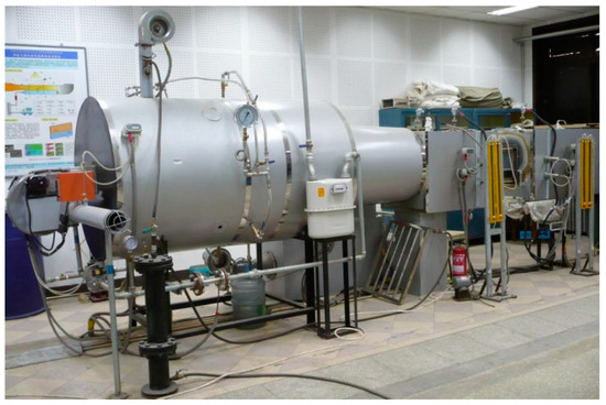
Figure 1.
Highly thermally loaded film cooling test rig.
2.1. Hot Gas and Coolant Air Supply Systems
Figure 2 shows the schematic representation of the test rig. The hot main gas system includes a fuel injection section and a burner section and produces hot gas with a temperature of 800 °C. The fuel is mixed with air and is ignited in a 380 Mcal/h burner. The fuel is liquefied petroleum gas (LPG) and has a flow rate from 15 to 30 kg/h, regulating the burner output power at a range of 200 to 400 Mcal/h. The combustion products leave the burner with a temperature of ~2000 °C and enter the diluting section. The hot gas is mixed with the diluting air and the sprayed water, supplied by the top blower and the water supply system, respectively. The resulting hot multicomposition gas is 800 °C.
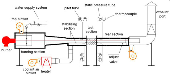
Figure 2.
Schematic representation of test rig.
The second system is the water supply system, which is used to adjust the hot gas composition with water. Eight spraying nozzles are spaced equally around the diluting section, delivering the diluting water into the section. The water flow rate is adjusted by the water supply pressure. The secondary coolant air is generated by a second blower and then is heated by an electric heat exchanger. The resulting air temperature is ~400 °C. Both the mainstream and coolant air channels are covered with heat-insulated layers.
2.2. Test Section
The test section is composed of an internal cooling side and a film cooling side, which is a typical cooling section of a turbine airfoil. The film cooling side hot gas temperature is 800 °C and the internal cooling side air temperature is 400 °C. The film cooling side and the internal cooling side are separated by a nickel-based superalloy flat plate with a thickness of 18 mm, as shown in Figure 3. A row of seven film holes are arranged on the nickel-based superalloy plate, with a hole diameter of 8 mm. The film hole pitch is 3 D, the hole inclination angle is 35°, and the length of the hole is L = 3.92 D. The distance between the trailing edge of the holes and the inlet of the plate is 11 D, while between the trailing edge of the holes and the outlet of the plate is 42 D. On the top surface of the superalloy plate, TBC is sprayed by utilizing APS (Air Plasma Spraying) method, which is shown in Figure 4. The top coat is 0.5 mm thick and the bond coat is 0.2 mm thick. The thermal conductivities of the superalloy plate and TBC are 20 W/mK and 2 W/mK, respectively, which are measured at 550 °C; however they will change with temperature.
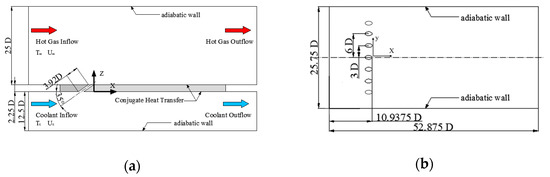
Figure 3.
Schematic drawing of the test section. (a) Front view of the test section; (b) Top view of the film-cooled plate.
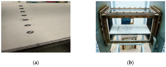
Figure 4.
Superalloy plate and test section. (a) Photo of the superalloy plate; (b) Photo of the test section.
The hot gas and the coolant air are at a speed of 15–20 m/s. An adjustable valve is installed in the cooling air channel, and by decreasing the flow area of the coolant air channel, the back pressure of the coolant air channel is higher than that of the hot gas channel. The blowing ratios are varied by adjusting the coolant and mainstream pressure difference.
2.3. Measurement System
The measuring system includes the pitot tubes, the static pressure tubes, the thermocouples, and the chromatographic analyzer. Four thermocouples are implemented at the center point of inlet and outlet of mainstream channel and coolant channel, measuring the temperatures of the inflow and the outflow, as shown in Figure 2. The inflow velocity is obtained by two pitot tubes that are installed in the center of each channel at the inlet of the test section. The back pressures of the channels are acquired by the static pressure tubes located at the outlet of the test section. In the downstream area of the centered film cooling hole, 90 thermocouples are installed on the top surface, bottom surface, and the middle of the plate, as shown in Figure 5 and Table 1. The gas collecting tube locates at the stabilizing section of the hot main gas channel. The composition of the hot gas is determined by the chromatographic analyzer from the gas sample collected.
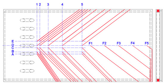
Figure 5.
Schematic drawing of thermos couple positions on the plate.

Table 1.
Positions of the thermocouples.
The measurement uncertainty of the thermocouple is 0.3% and of chromatographic analyzer is 2.2%. The uncertainty of the test system for temperature measurement is ~2.3%. The correction factors of the pitot tubes and the static tubes are calibrated to be unity.
3. Numerical Methodology
The numerical algorithm applied in the present study is conjugate heat transfer method, which considers the thermal conduction, convection, and radiation in the computation. Commercial software ANSYS CFX 12.1 was adopted for all the numerical studies. The radiation heat transfer equation is solved by utilizing the discrete transfer radiation model (DTM). The absorption coefficient of the gas is determined by the weighted sum of gray gases (WSGG) spectral model. The numerical method is validated by comparing computational results with the experimental data.
3.1. Test Section Radiation Model
In the present study, the discrete transfer model (DTM) was employed due to the optical thickness of the radiation is less than unity. The DTM depends upon the discretization of the equation of transfer along multiple rays leaving from the bounding surfaces. The radiation transport governing equation is expressed as follows.
The DTM assumes that operating system is homogeneous. The intensity Iv is solved along the rays leaving from the boundaries in the following form.
The homogeneity assumption is maintained to extend the solution to the entire domain. It is then integrated over a solid angle to obtain the spectral incident radiation and the radiative heat flux at discrete points.
3.2. Spectral Model
For computation of the gas radiation properties, the weighted sum of gray gases (WSGG) model is the most widely used model option, which is a compromise between the complete model that considers the absorption bands [25] and the oversimplified gray gas model. The WSGG model is combined with the DTM to obtain the emissivity of H2O and CO2. In the WSGG model, the gas emissivity is a weighted sum of gray gas emissivity in the following expression.
where aj and kj are the weighting factor and the absorption coefficient for the jth gray gas component, respectively. s is the path length. There exists a constraint that the sum of coefficients aj is equal to unity when calculating the coefficients of aj and kj. The transparent regions of the spectrum are indicated by the term j = 0. The coefficients (aj and kj) from references [26,27] are used in the study. The partial pressure ratios of H2O and CO2 (H2O/CO2) are 1 and 2 when the number of gray gases is three [26]. The coefficients are applied when gas temperature falls within the range of 600 to 2000 K and the partial pressure-path length products are from 0.001 to 10.0 atm-m. The property values are adequately predicted and are designated as “Smith 4GG”. The partial pressure ratios of H2O and CO2 (H2O/CO2) are 2 and 3 when the number of gray gases is four [27]. The model is designated as “Perry 5GG”. A more detailed description of the model can be found in reference [28].
3.3. Computational Geometry and Domain
The computational geometry is similar to the test section, including hole geometries, coolant, and mainstream supply system. The inlet and outlet sections are extended by 10 D to generate stable flow boundary conditions as shown in Figure 6. Figure 7 shows the multiblock structured mesh, which is refined near the film-cooling holes and near-wall regions. More than 10 points are implemented in the boundary layer to achieve y+ less than unity. The total element amount of the mesh is ~7.94 million. A grid refinement was conducted to generate a mesh with 12.20 million cells and check mesh independent study. The results show that the two sets of meshes behave quite similar, and hence the mesh with 7.94 million cells is adopted in the present simulations.
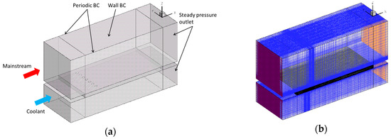
Figure 6.
Computational domain and the structured mesh. (a) Computational domain. (b) Multiblock structured mesh.
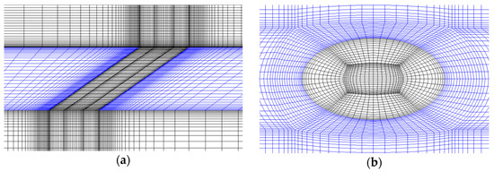
Figure 7.
Details of the structured mesh. (a) Refined mesh near the plate and (b) refined mesh around the film cooling hole.
3.4. Turbulence Model and Boundary Conditions
The SST k-ω turbulence model of Menter is adopted in the steady RANS simulations. The k-ω model is used in near wall regions and the k-ε model is switched on in mainstream region. The mass flow rate boundary condition is applied at the inlet section and steady pressure is applied at the outlet section. The top and bottom surfaces of the test plate are heat transfer interface between fluid and solid domain. The other walls around the fluid domain are temperature wall; the temperatures are measured by thermocouples.
3.5. Material Parameters
In the present simulations, the specific heat and thermal conductivity of the nickel-based superalloy vary with temperature and are provided in reference [29]. The emissivity of the nickel-based superalloy plate was set to 0.79 [30]. Ideal gas assumption is used in the simulations, where the specific heat capacity of the gas is calculated by the NASA format polynomials. The gas transport properties are obtained from the REFPROP program that is an acronym for reference fluid properties [31].
3.6. Validation of the Numerical Algorithm
Based on the configuration of the test rig, three gas composition cases are studied to validate the numerical algorithm. The gas compositions of each case are listed in Table 2 [28]. Varying the steam humidity of hot gas can change the gas composition. Other boundary conditions of the three experimental cases keep the constant, which is shown in Table 3. The blowing ratio is calculated to be 1.0.
Table 2.
The experimental hot gas compositions.
Table 3.
Experimental boundary conditions.
Figure 8 shows the experimental and numerical centerline temperature distribution along the centerline on the top and bottom plate surfaces. The red line indicates temperature distribution on the top surface, and the green line indicates the temperature distribution on the bottom surface. It is shown that the numerical results agree well with the experimental results for three cases. Therefore, it is concluded that the DTM and WSGG model are adequately accurate for the present cases.
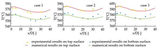
Figure 8.
Centerline temperature distribution on the top and bottom surfaces of the film-cooled plate.
4. Results and Discussion
4.1. Effect of Radiative Heat Transfer
A pair of numerical cases with/without radiation are carried on to study the effect of radiative heat transfer based on the validated algorithm. The numerical study corresponds to a selected test cases with a mass fraction of H2O is 7.92. The detailed information of the selected test case could be found in reference [32].
The temperature distributions on the top and bottom sides of film plate resulted from the numerical study are showed in Figure 9 for both with/without radiation cases. It is noted that the temperature level is significantly increased after considering the radiation for both the upper and bottom surfaces. Also, the temperature patterns change if the plate is subjected to radiation, especially on the top surface where film cooling occurs.
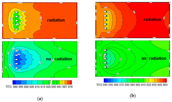
Figure 9.
Temperature distribution with/without radiation (a) on the top surface and (b) on the bottom surface.
Continually, the spanwise temperature profiles on the top plate surface at x/D = 1 in both cases are shown in Figure 10. It is noted that, on both top and bottom surfaces near the film cooling hole, the temperature profile in the spanwise direction becomes smoother when considering the radiation. This means radiation decreases the temperature gradient in the spanwise direction.
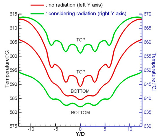
Figure 10.
Spanwise temperature profile on the top plate surface, X/D = 1.
To further quantify the effect of radiative heat transfer, the normalized temperature, η, is defined in the following expression.
where Tg, Tc, and Tw are the temperatures of the hot gas, the coolant air and the top surface wall. The normalized temperature is similar to the film cooling effectiveness when the plate surface is adiabatic.
Figure 11 shows line plots of η along the centerline of the plate top surface, an adiabatic case is employed as the basic. Compares with the case with no radiation, the normalized temperature of the case with radiation is ~0.2 lower, and even is lower than the adiabatic effectiveness before x = 13 D, the high cooling effectiveness near the holes almost disappears. That is to say, the film cooling effect is weakened by radiation while it further smears out the temperature gradient. In real engine conditions, the hot main gas temperature will be higher than 1200 °C (much higher than the condition of the test rig), leading to high surface temperature and a high local temperature gradient, which will result in significant thermal-mechanical load. The radiation enhances the increase in temperature but weakens the temperature gradient.
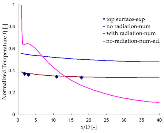
Figure 11.
Normalized temperature along the centerline of the top plate surface.
4.2. Effect of Hot Gas Composition
The effect of the hot gas composition on the film cooling system is investigated by varying five different kinds of fuel. The hot gas compositions for each fuel are listed in Table 4 [28].
Table 4.
Hot gas compositions in the numerical study 1
Figure 12 shows the temperature distribution along the centerline of the top surface for five different fuels, with and without considering the radiation. Without considering radiative heat transfer, the temperature distributions are similar for five different fuel cases. Nitrogen is the major composition of the hot gases and its mole fraction is more than 70%, while steam is the major composition of the combustion product of oxy and its mole fraction is 82%. Therefore, it is observed that the temperature distribution for the combustion product of oxy is ~15 °C higher than the other four gases. When considering the radiative heat transfer, a temperature increase of ~50 °C is observed. A great temperature rise occurs for the combustion product of the natural gas, which leads to a quite close temperature distribution to that of the combustion product of the oxy-fuel gas.
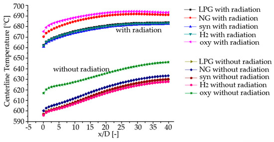
Figure 12.
Temperature distribution along the centerline of the plate with/without radiation.
4.3. Effect of Thermal Barrier Coating (TBC)
The effect of thermal barrier coating on the heat transfer performance was experimentally investigated. Three different hot gas compositions were investigated after spraying TBC on the top surface of the plate. Table 5 shows the different gas compositions with and without TBC.
Table 5.
Hot gas compositions in experiments with/without thermal barrier coating (TBC).
Figure 13 shows the experimental centerline temperature results on the top and bottom sides of the film plate. It is observed that the temperature patterns show a quite similar trend with and without TBC. In particular, the temperature is at a high value at the inlet, then decreases as x/D increases, and increases at the downstream region.
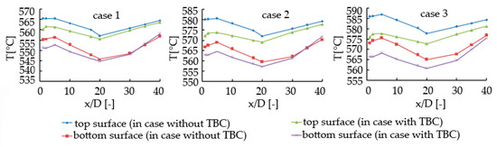
Figure 13.
Temperature along the centerline of the test plate surface.
The temperature drops inside TBC are shown in Figure 14, which is derived from the results of three pairs of cases. It is clear that, in case 3, a higher percentage of steam results in a greater temperature drop. By observing the temperature drop distribution with x/D, it is observed that the temperature drop reaches maximum value at the entrance section and decrease as x/D increases. This is associated with the radiation distribution feature, i.e., a larger humidity causes a stronger radiation. Therefore, the radiation is strongest at the entrance section, and grows weaker as x/D increases, which indicates the temperature drop by TBC is higher when radiation effect is stronger.
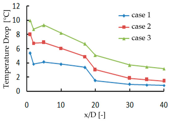
Figure 14.
Temperature decrease inside TBC along the centerline of the test plate top surface.
Therefore, we conclude that the heat insulation effect of TBC grows more obvious when the radiation effect is significant. This is caused by the radiation property differences between TBC and the nickel-based alloy. However, when TBC is coated, over 50% of the radiation heat transfer is reflected by TBC, which means TBC absorbs less radiation heat than superalloy and protects the metal substrate. Another advantage of TBC is that it smooths the temperature distribution and decreases the temperature gradient to some extent [33].
5. Conclusions
Gas turbine film cooling system shows complicated flow and heat transfer characteristics due to the interaction of heat conduction, heat convection, and radiation heat transfer. In the present study, the conjugate heat transfer characteristics of a film cooling system are experimentally and numerically analyzed. The topics include the radiation heat transfer, multicomposition gas, and TBC. In solving the radiative heat transfer in the multicomposition field, the Discrete Transfer Model (DTM) and the Weighted Sum of Gray Gases (WSGG) spectral model were employed and validated.
The results show that the surface temperature increase significantly and the temperature gradient through the plate becomes much larger when the radiation is considered. It is also observed that a higher percentage of steam in gas composition results in a higher temperature (lower normalized temperature) on the film-cooled plate. In particular, the normalized temperature on the film-cooled plate decreases ~0.02 as the percentage of steam in hot gas increases per 7%. Furthermore, the heat insulation effect of TBC grows more obvious when the radiation heat transfer is stronger. Also observed is that TBC smooths the temperature distribution and thus decreases the temperature gradient to some extent.
Author Contributions
J.R. guided and summarized the work, X.L. and H.J. conceived the idea.
Funding
This research was funded by Projects 51076076 and 51110105013 supported by National Natural Science Foundation of China.
Acknowledgments
The authors appreciate the brilliant work of Wenping Wan, Peng Sun, Mingfei Li and Hong Yin on the thermally loaded film cooling test rig and the numerical simulation. Thanks also to Weihong Li, who summarized the work of the research group on the topic.
Conflicts of Interest
The authors declare no conflict of interest.
Nomenclature
| Emission weighting factor | (-) | |
| Diameter of the hole | (m) | |
| Spectral black body emission intensity | (Wm−3sr−1) | |
| Spectral radiation intensity | (Wm−3sr−1) | |
| Radiation Intensity leaving the boundary | (Wm−3sr−1) | |
| Spectral absorption coefficient | (m−1) | |
| Spectral scattering coefficient | (m−1) | |
| Absorption coefficient | (m−1) | |
| Length of the hole | (m) | |
| Number of gray gases | (-) | |
| Position vector | (m) | |
| S | Radiation intensity source term | (Wm−4sr−1) |
| Path length | (m) | |
| Direction vector | (m) | |
| T | Temperature | (K) |
| Cartesian coordinates | (m) | |
| Dimensionless wall distance | (-) |
Greeks
| ε | Total gas emissivity | (-) |
| η | Normalized temperature | (-) |
| Frequency | (s−1) | |
| Solid angle | (sr) |
Subscripts
| Coolant flow | |
| Gas | |
| Index | |
| w | Wall |
Acronyms
| DTM | Discrete transfer model |
| RTE | Radiation transport equation |
| WSGG | Weighted sum of gray gases |
References
- Mazzotta, D.W.; Chyu, M.K.; Alvin, M.A. Airfoil Heat Transfer Characteristics in Syngas and Hydrogen Turbines; ASME Paper, No. GT2007-28296; ASME: New York, NY, USA, 2007. [Google Scholar]
- Bohn, D.; Bonhoff, C. Combined Aerodynamic and Thermal Analysis of a Turbine Nozzle Guide Vane; IGTC Paper 95-108; Gas Turbine Society of Japan: Tokyo, Japan, 1995. [Google Scholar]
- Bohn, D.; Heuer, T. Conjugate Flow and Heat Transfer Calculation of a High Pressure Turbine Nozzle Guide Vane. In Proceedings of the 37th Joint Propulsion Conference and Exhibit, Salt Lake City, UT, USA, 8–11 July 2001. [Google Scholar]
- Bohn, D.; Becker, V.; Kusterer, K.; Otsuki, Y.; Sugimoto, T.; Tanaka, R. 3-D Internal Conjugate Calculations of a Convectively Cooled Turbine Blade with Serpentine-Shaped Ribbed Channels. In Proceedings of the ASME 1999 International Gas Turbine and Aeroengine Congress and Exhibition, Indianapolis, IN, USA, 7–10 June 1999. [Google Scholar]
- Bohn, D.; Ren, J.; Kusterer, K. Conjugate Heat Transfer Analysis for Film Cooling Configurations with Different Hole Geometry. In Proceedings of the ASME Turbo Expo 2003, Collocated with the 2003 International Joint Power Generation Conference, Atlanta, GA, USA, 16–19 June 2003. [Google Scholar]
- Hansmann, T.; Wilhelmi, H.; Bohn, D. An Experimental Investigation of the Film-Cooling Process at High Temperatures and Velocities. In Proceedings of the 5th International Aerospace Planes and Hypersonics Technologies Conference, Munich, Germany, 30 November–3 December 1993. [Google Scholar]
- Bohn, D.; Becker, V. 3-D Conjugate Flow and Heat Transfer Calculations of Film-Cooled Turbine Guide Vane at Different Operation Conditions. In Proceedings of the ASME 1997 International Gas Turbine and Aeroengine Congress and Exhibition, Orlando, Florida, USA, 2–5 June 1997. [Google Scholar]
- Mansour, M.L.; Hosseini, K.M.; Liu, J.S. Assessment of the Impact of Laminar-Turbulent Transition on the Accuracy of Heat Transfer Coefficient Prediction in High Pressure Turbines. In Proceedings of the ASME Turbo Expo 2006: Power for Land, Sea, and Air, Barcelona, Spain, 8–11 May 2006. [Google Scholar]
- Heidmann, J.D.; Kassab, A.; Divo, E.A.; Rodriguez, F.; Steinthorsson, E. Conjugate Heat Transfer Effects on a Realistic Film-Cooled Turbine Vane. In Proceedings of the ASME Turbo Expo 2003, collocated with the 2003 International Joint Power Generation Conference, Atlanta, GA, USA,, 16–19 June 2003. [Google Scholar]
- Hylton, L.D.; Milhec, M.S.; Turner, E.R.; Nealy, D.A.; York, R.E. Analytical and Experimental Evaluation of the Heat Transfer Distribution Over the Surface of Turbine Vanes; NASA CR-168015; NASA: Washington, DC, USA, 1983.
- Hylton, L.D.; Nirmalan, V.; Sultanian, B.K.; Kaufman, R.M. The Effects of Leading Edge and Downstream Film Cooling on Turbine Vane Heat Transfer; NASA CR-182133; NASA: Washington, DC, USA, 1988.
- Dees, J.E.; Bogard, D.G.; Ledezma, G.A.; Laskowski, G.M. Overall and Adiabatic Effectiveness Values on a Scaled Up, Simulated Gas Turbine Vane: Part I—Experimental Measurements. In Proceedings of the ASME 2011 Turbo Expo: Turbine Technical Conference and Exposition, Vancouver, BC, Canada, 6–10 June 2011; pp. 571–582. [Google Scholar]
- Ledezma, G.A.; Laskowski, G.M.; Dees, J.E.; Bogard, D.G. Overall and Adiabatic Effectiveness Values on a Scaled Up, Simulated Gas Turbine Vane: Part II—Numerical Simulations. In Proceedings of the ASME 2011 Turbo Expo: Turbine Technical Conference and Exposition, Vancouver, BC, Canada, 6–10 June; pp. 595–605.
- Dees, J.E.; Bogard, D.G.; Ledezma, G.A.; Laskowski, G.M. The Effects of Conjugate Heat Transfer on the Thermal Field above a Film Cooled Wall. In Proceedings of the ASME 2011 Turbo Expo: Turbine Technical Conference and Exposition, Vancouver, BC, Canada, 6–10 June 2011; pp. 607–617. [Google Scholar]
- Kumar, A.; Kale, S.R. Numerical simulation of steady state heat transfer in a ceramic-coated gas turbine blade. Int. J. Heat Mass Transf. 2002, 45, 4831–4845. [Google Scholar] [CrossRef]
- He, Z.H.; Tan, H.P.; Liu, L.H.; Feng, G.T.; Ruan, L.M. Numerical computation on blade channel radiation in engine. J. Propuls. Technol. 2001, 22, 65–68, 88. [Google Scholar]
- Zhang, L.; Liu, Z.; Lian, X. Numerical study of 3D heat transfer for turbine blade with air cooling. J. Aerosp. Power 2007, 22, 1268–1272. [Google Scholar]
- Akwaboa, S.; Mensah, P.; Diwan, R. Effects of Thermal Radiation on Air Plasma Spray (APS) Coated Gas Turbine Blade. In Proceedings of the ASME Turbo Expo 2010: Power for Land, Sea, and Air, Glasgow, UK, 14–18 June 2010. [Google Scholar]
- Mazzotta, D.W.; Karaivanov, V.G.; Chyu, M.K.; Slaughter, W.S. Gas-Side Heat Transfer in Syngas, Hydrogen-Fired and Oxy-Fuel Turbines. In Proceedings of the ASME Turbo Expo 2008: Power for Land, Sea, and Air, Berlin, Germany, 9–13 June 2008. [Google Scholar]
- Na, S.; Dennis, R.A.; Alsup, C.; Bryden, K.M.; Shih, T.I.-P. Effects of Hot-Gas Composition on Temperature Distribution in a Flat Plate Cooled by Internal and Film Cooling. In Proceedings of the ASME Turbo Expo 2009: Power for Land, Sea, and Air, Orlando, FL, USA, 8–12 June 2009. [Google Scholar]
- Moliere, M. Hydrogen-fuelled gas turbines: Status and prospects. In Proceedings of the 2nd CAME-GT conference, Bled, Slovenia, 29–30 April 2004. [Google Scholar]
- Feuerstein, A.; Knapp, J.; Taylor, T.; Ashary, A.; Bolcavage, A.; Hitchman, N. Technical and economical aspects of current thermal barrier coating systems for gas turbine engines by thermal spray and EBPVD: A review. J. Therm. Spray Technol. 2008, 17, 199–213. [Google Scholar] [CrossRef]
- Bohn, D.; Krewinkel, R. Influence of a Broken-Away TBC on the Flow Structure and Wall Temperature of an Effusion Cooled Multi-Layer Plate Using the Conjugate Calculation Method. In Proceedings of the ASME Turbo Expo 2008: Power for Land, Sea, and Air, Berlin, Germany, 9–13 June 2008; pp. 351–362. [Google Scholar]
- Davidson, F.T.; Dees, J.E.; Bogard, D.G. An Experimental Study of Thermal Barrier Coatings and FilmCooling on an Internally Cooled Simulated Turbine Vane. In Proceedings of the ASME 2011 Turbo Expo: Turbine Technical Conference and Exposition, Vancouver, BC, Canada, 6–10 June 2011; pp. 559–570. [Google Scholar]
- Cui, Y.F.; Xu, G.; Yu, B.; Nie, C.Q.; Huang, W.G. The Effects of Pressure on Gas Turbine Combustor Performance: An Investigation via Numerical Simulation. In Proceedings of the ASME Turbo Expo 2006: Power for Land, Sea, and Air, Barcelona, Spain, 8–11 May 2006. [Google Scholar]
- Smith, T.F.; Shen, Z.F.; Friedman, J.N. Evaluation of Coefficients for the Weighted Sum of Gray Gases Model. Trans. ASME 1982, 104, 602–608. [Google Scholar] [CrossRef]
- Krishnamoorthy, G. A New Weighted-Sumof-Gray-Gases Model for CO2-H2O Gas Mixtures. Int. Commun. Heat Mass Transf. 2010, 37, 1182–1186. [Google Scholar] [CrossRef]
- Sun, P.; Wang, W.; Ren, J.; Jiang, H. Effect of the Hot Gas Composition on a Highly Thermally Loaded Film Cooling System. In Proceedings of the ASME 2011 Turbo Expo: Turbine Technical Conference and Exposition, Vancouver, BC, Canada, 6–10 June 2011. [Google Scholar]
- Kermanpur, A.; Varahram, N.; Davami, P.; Rappaz, M. Thermal and Grain-Structure Simulation in a Land-Based Turbine Blade Directionally Solidified with the Liquid Metal Cooling Process. Metall. Mater. Trans. B 2000, 31, 1293–1304. [Google Scholar] [CrossRef]
- Hottel, H.C.; Noble, J.J.; Sarofim, A.F.; Green, D.W.; Perry, R.H. Chapter 5: Heat and Mass Transfer. In Perry’s Chemical Engineers’ Handbook, 8th ed.; McGraw-Hill: New York, NY, USA, 2007. [Google Scholar]
- ‘‘REFPROP: (NIST).”. Available online: http://www.boulder.nist.gov/div838/theory/refprop/Frequently_asked_questions.htm#Updates. (accessed on 12 November 2018).
- Wang, W.; Sun, P.; Ren, J.; Jiang, H. Radiative Effectiveness on the Aero- and Thermodynamics in a Highly Thermally Loaded Film Cooling System. In Proceedings of the ASME 2011 Turbo Expo: Turbine Technical Conference and Exposition, Vancouver, BC, Canada, 6–10 June 2011. [Google Scholar]
- Li, M.; Yin, H.; Ren, J.; Jiang, H. Conjugate Heat Transfer Characteristics of a Highly Thermal-Loaded Film Cooling System in Hot and Multicomposition Gas Condition. J. Heat Transf. 2015, 138, 024503. [Google Scholar] [CrossRef]
© 2019 by the authors. Licensee MDPI, Basel, Switzerland. This article is an open access article distributed under the terms and conditions of the Creative Commons Attribution (CC BY) license (http://creativecommons.org/licenses/by/4.0/).