Energy Harvesting Performance of Plate Wing from Discrete Gust Excitation


1
School of Aeronautic Science and Engineering, Beihang University, Beijing 100191, China
2
Faculty of Engineering and Physical Sciences, University of Southampton, Southampton SO171BJ, UK
*
Author to whom correspondence should be addressed.
Aerospace 2019, 6(3), 37; https://doi.org/10.3390/aerospace6030037
Submission received: 30 December 2018
/
Revised: 9 March 2019
/
Accepted: 9 March 2019
/
Published: 15 March 2019
(This article belongs to the Special Issue Aeroelasticity)
Abstract
:Energy harvesting from aeroelastic response tends to have a wide application prospect, especially for small-scale unmanned aerial vehicles. Gusts encountered in flight can be treated as a potential source for sustainable energy supply. The plate model is more likely to describe a low aspect ratio, thin plate wing structure. In this paper, the Von Kármán plate theory and 3D doublet lattice method, coupled with a piezoelectric equation, are used to build a linear state-space equation. Under the load of “one-minus-cosine” discrete gust, the effects of flow speed and gust amplitude, thickness of piezoelectric ceramic transducer (PZTs) layers, and mounted load resistance are investigated. Results reveal that the PZTs layers on the wing root of the leading edge can obtain the highest electrical parameters. The flow velocity, thickness of the PZTs layers and load resistance are used to optimize energy harvesting data.
1. Introduction
In the last few years, numerous studies have reached a consensus that energy harvesting (EH) from aeroelastic response has a potential application foreground [1,2,3]. Aeroelastic flutter characteristics can be a new approach to generate electricity from wind power, or be a direct replenishment to provide energy for an aircraft itself [4].
The expanded direction of EH is to generate wind power by using the flow-induced vibration from wing section or thin plate. It is considered as a substitute for a traditional wind turbine on miniaturization. Mckinney et al. [5] designed a device, which drives the wing section into an aeroelastic flutter under a certain flow speed and transforms plunge motion into rotation to drive an electromagnetic generator. Bryant et al. [6,7] proposed the other way to perform aeroelastic flutter EH by using piezoelectric materials, and researching the base structure character, which replaced the wing section with a rigid plate. Orrego et al. [8] investigated equipment for collecting wind power with a polyvinylidene fluoride (PVDF) membrane, a type of organic piezoelectric material. The adopted inverted-flag configuration can maintain the flutter motion in a wider range of wind speeds and the flutter boundary can be changed by tailoring the length-width ratio. An airfoil with double plunge degrees of freedom was proposed by Wu et al. [9]. Wu’s model can collect extra EH power from airfoil plunge motion, which can be a complement for the single pitch motion EH system in Reference [1].
With the development of small-scale unmanned aerial vehicles (UAVs), a contradiction exists between weight reduction and the penalty associated with a power source. The duration of power supply, which is limited by the energy density of carried fuel or batteries, restricts the ability to perform tasks. EH from the phenomenon of aeroelastic response was suggested as an additional energy refill method, as was solar radiation. The main aeroelastic responses of the wing structure are flutter, limit cycle oscillations (LCOs) and gust response, although they are considered as negative phenomena since in many cases these unwanted vibrations may cause a reduction in life span and structural damage.
Giacomello et al. [10] used a plate covered with ionic metal polymeric materials (IPMC) for EH of LCOs. Dunnmon et al. [11] placed a piezoelectric material at the root of a plate, and both numerical simulation and experimental results showed that the device can gain about 17% total energy from flow. Tang et al. [12] developed a piezoelectric-aeroelastic coupled system based on the composite material laminate plate and analyzed power efficiency by changing the yawed flow angle. Aeroelastic vibration EH from a cantilevered plate wing with embedded piezoceramics was demonstrated by Marqui et al. [13]. The model was based on the frequency-domain and discussed the output electrical feature under the variables of different airflow speed and electrical boundary conditions. Wu et al. [14] built a coupled pitch-plunge-leadlag airfoil-based piezoaeroelastic EH model and compared the power outputs from the plunge and leadlag motions. The influence of nonlinear dynamic behaviors for the proposed EH system was discussed.
Gust response is more likely to be encountered in the practical flight [15]. Many studies have been completed on gusts, such as analysis of gust response [16], multi-objective gust optimization [17], and gust alleviation control [18], although these purposes aim to alleviate the influence of gust. From a different point of view, gusts can provide a potential source for EH. Pozzi et al. [19] studied EH from a wing structure under gust loads using engineering softwares Nastran and Ansys. Wu et al. [9] built a coupled piezo-aeroelastic model for the analysis of EH from the gust response and evaluated the energy conversion efficiency and material utilization efficiency.
The aim of this paper is to investigate EH of a plate wing model under the discrete gust load based on previous work by Wu et al. [20]. From the results of the beam model EH [20], an aeroelastic response converges rapidly via relevant high bending and twisting stiffness, and the time point of the highest voltage output is around the end of gust encounter phase. The different EH phenomena of the beam model can be found in Bruni et al. [21], for the obvious aeroelastic response behavior, the highest power output (as well as voltage) occurs in the phase of free response phase. EH from gust response behavior of the plate model wing structure was adopted and evaluated as a notable low bending and twisting stiffness model [13]. According to the two above-mentioned beam models, plate structure seems to be more of the latter. To analyze its EH characteristics, the proportions of EH output at each phase need to be assessed under certain conditions. Furthermore, the data differences with the location variation of the chord direction can also be calculated using the 2-D plate feature. In this paper, the kinetic equation is established using linear plate theory, unsteady aerodynamics and coupled with the piezoelectric equation. A discrete “one-minus-cosine” gust is loaded as a base excitation. EH properties of the model are studied based on the time-domain state-space equations. The performance of energy output of aeroelastic response is quantified in the voltage, electrical power and energy. For further analysis, the effect of flow speed and gust intensity, piezoelectric ceramic transducer (PZTs) thickness, location and load resistance value are discussed by comparing the data of the energy output density.
2. Aeroelectroelastic Model
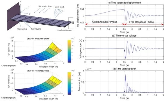
The piezoaeroelastic model is designed as a thin cantilevered plate wing and covered with piezoelectric plates, shown in Figure 1. The piezoelectric materials, covered by continuous and perfectly conductive electrodes with certain thickness, are placed along the elastic axis symmetrically. The transducers and the substructure are assumed to be perfectly bonded together. The wing is in subsonic flow and subject to a vertical discrete gust load. The load resistance is mounted for the charging circuit. Every blocked symmetric PZTs on both sides can be calculated separately.
2.1. Structural Model
The structure model is based on the bending motion equation of Von Karman large deflection equations, coupled with piezoelectric layers. The equation of motion of the plate wing is
where is the displacement at plate location at time ; , and are the mass, damping and stiffness matrix; is the aerodynamic force matrix.
The e-form piezoelectric equations are [22]:
where and are the stress vector, electric displacement vector, electric field vector, and strain vector; and are the elastic stiffness matrix, piezoelectric stress matrix, and matrix of permittivity components. The superscripts and indicate that corresponding parameters are measured at a constant electric field and a constant strain, respectively; the superscript indicates transposition.
The Rayleigh-Ritz approach is used to discretize the system. The deflection is assumed to be:
where is the order modal function of the piezoelectric cantilevered wing; is the order modal time coordinate.
Combining Equations (1)–(3), a generalized form of the coupled aeroelectroelastic flow-induced vibration based EH model [13] can be expressed as:
where is the vector describing the structural states; is the piezoelectric coefficient matrix; is the piezoelectric voltage output vector; is the equivalent piezoelectric capacitance matrix; is the applied load resistance. The formula derivation can also be found in Reference [20].
2.2. Aerodynamic Model
The linear unsteady aerodynamic model is the doublet lattice method (DLM) [23], which is a finite element method for the oscillatory, subsonic, inviscid lifting surface theory. The thin wing can be assumed as a lift surface and divided into several “box” elements with doublet singularities of constant strength in chordwise and parabolic strength in spanwise direction. These segments are arranged in columns parallel to the freestream, surface edges and fold lines lie on the boundaries. The 1/4 chord line of each box is taken to contain a distribution of acceleration potential doublets of uniform but unknown strength. The control point, arranged at the cross of 3/4 chord and half span lines, is verified boundary condition.
The integral pressure-wash equation for multiple interfering surfaces is:
Where is the induced downwash at the surface; is the kernel function for nonplanar surface; is the number of divided lifting surfaces; is the dimensionless lifting pressure coefficient; and are dummy variables of integration over the area of the wing in spanwise direction y and chordwise direction x.
In matrix notation, Equation (5) becomes
where is the downwash factor matrix related to the kernel function; is the density of air; is the airflow speed; is the downwash caused by the discrete gust. In general, the gust is represented in discrete or continuous forms. A relative realistic discrete gust model that allows for the spatial scale of the gust zone is the “one-minus-cosine” model. The vertical velocity of the gust is [23]:
where is the gust velocity amplitude; is the generalized wind discrete scale; is the distance that the wing travels in the gust.
Note that this model is based on the frequency-domain procedures, which is not conveniently adaptable to the consideration of aeroelastic gust response. The time-domain equation of motion is more suitable for establishing a liner state-space model for the discrete gust analysis. The minimum state approach can describe the time-domain aerodynamic force and the discrete gust by using a rational function of the Laplace variable s [24],
where is the frequency-domain aerodynamic force matrix; are approximation matrix; is the half chord length.
Combining Equations (5)–(8), the time-domain aerodynamic lift is approximated to
where is augmenting aerodynamic state vector.
2.3. State-Space Model
Combining Equation (4) with the aerodynamic model of Equation (9), the aeroelastic model in the time-domain state-space form is obtained,
where are the combined mass, damping and stiffness matrix obtained from Equation (4);
2.4. Performance Analysis
The power output is
where and are the voltage from upper and lower PZTs.
The electric energy harvested is
where is the time span for the energy output.
The energy output density is introduced to evaluate the performance of the harvester, namely, the energy output per unit volume of the PZTs,
where is the volume of PZTs layers.
3. Results and Discussions
The initial geometric and material properties of the plate wing and PZTs layers are given in Table 1 and Table 2. The wing structure is made of aluminum Al 7075, and the PZTs material is PZT-5H.
The operating conditions for the subsequent results are as follows; cruise speed of 40 m/s, 1500 m above sea level, the gust shape was for a discrete “one-minus-cosine” function with peak intensity of 5 m/s, a gust wavelength of 100 m, and the gust interacts with the wing at the initial time. The displacement is measured at the leading edge of the wing tip, where the EH data was collected from a pair of PZTs layers at the leading edge of the wing root for the highest energy output density.
The range of gust intensity was chosen from ESDU 04024 [25]. For 40 m/s cruise speed, 1500 m altitude and two hours flight, the largest gust intensity occurred more than once is 5 m/s. The comparison of gust amplitude is from a higher probability condition 3 m/s (more than twice during a flight) to an extreme condition 10.50 m/s (2% probability during a flight).
The flutter boundary should be determined initially as an important aeroelastic behavior. The linear flutter speed can be obtained from the state-space matrices (Equation (10)) using linear eigenvalue analysis. The stability and frequency of the system are determined by the real and imaginary parts of the eigenvalues. The flutter speed can be calculated when the real part of eigenvalues of the aeroelectroelastic system become positive.
The flutter characteristics of the wing model adopted is shown in terms of damping and frequency at an increasing airflow speed in Figure 2. The load resistance of EH system is 5.00 × 10⁴ Ω.
Results show that the real part of the eigenvalues first become positive at an airflow speed of 154 m/s and that the critical mode is a coupled 1 bending–1 torsional mode, as shown in Figure 2a. Figure 2b shows the frequency behaviors of the first three modes. The first six modes are listed in Table 3. It is noticed that all the modes present bending-torsional coupling for the plate model.
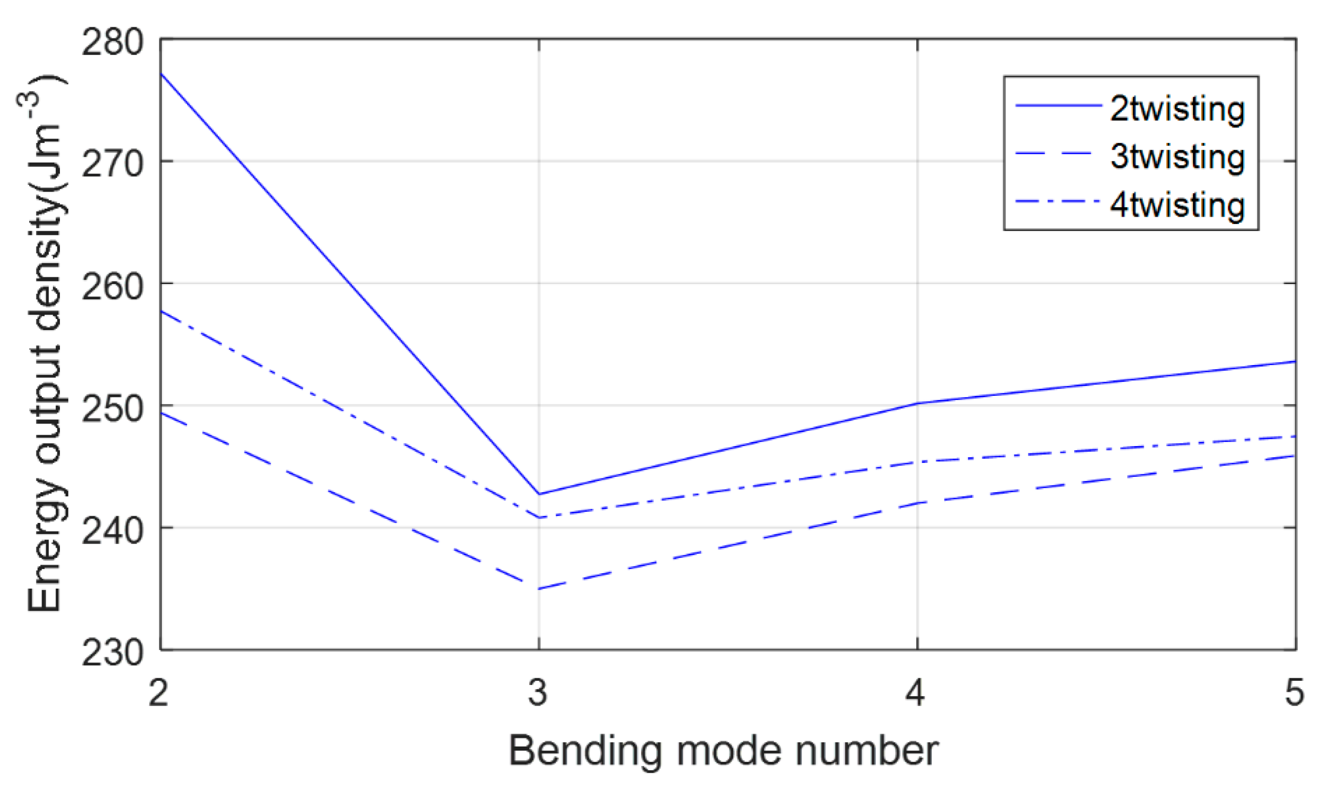
A preliminary study was carried out to investigate the number of mode shapes needed for converged results. The energy output density is chosen as a calibration criterion, which can be calculated from the combination of Equations (3), (10)–(13). Figure 3 shows the energy output density of the PZTs plates on both sides of the leading edge of the wing root.
Results show that the relative error between EH data of 5-bending coupled 4-twisting modes and the data of 5-bending coupled 3-twisting modes is 0.73%. Therefore, the results presented include the lowest 5 bending and 4 twisting modes.
3.1. Time-History Analysis
The time-history analysis of the gust response can be calculated from the state-space matrices (Equation (10)). The Fourth Order Runge-Kutta method is used to solve the motion equation of the system.
Results are presented in Figure 4. Figure 4a shows the tip displacement at the leading edge of the wing. Figure 4b shows the voltage output at the leading edge symmetric PZTs layers of the wing root, which has the highest EH output data. Figure 4c demonstrates the power output at the leading edge symmetric PZTs layers of the wing root, obtained from Equation (11).
The gust load lasts for 0.05 s in this condition, the gust duration is 2.50 s and the first 2.50-second response is selected of the voltage and power output. The detail EH energy data of every PZTs layers is shown in Figure 5, with the gust encounter presented in Figure 5a and free response power output in Figure 5b. The displacement of wing tip continues to increase until the peak 4.40 × 10⁻² m at 2.50 s during the end of gust wavelength. After the gust moves away from the wing the voltage and power output reach their peaks, −6.44 V and 8.29 × 10⁻⁴ W when the tip displacement springs back to −2.43 × 10⁻² m at 2.58 s. For all PZTs layers, EH power during the first second of gust response is 14.52 × 10⁻⁴ J, 95.68% of the total EH (15.18 × 10⁻⁴ J). During the gust interaction, the data are 1.30 × 10⁻⁵ J, 0.86%.
Results demonstrate that the voltage and power output have phase differences with the tip displacement, yet it is consistent with the stress changing. Comparing with the percent of EH data, EH is mainly from the first few seconds (from 2.50 s in Figure 4) when the wing disengaged from the gust zone. It can be considered that the main influence of the gust load is the modal displacement, modal velocity, augmenting aerodynamic state vector and voltage of structure and PZTs layers’ circuit system at the end of gust zone, as shown in Equation (10), which is also the initial condition at the beginning of free response phase.
Energy output differences of wing-like EH system in the chordwise direction PZTs layers need to be concerned. In the beam structure, it is neglected for the model limitation. As a 2-D model, the plate structure can demonstrate the energy output differences in the chordwise direction. The reason for the EH inconsistency in Figure 5 is that the differences are balanced by cycles of the torsional vibration (Figure 5b), unlike the disparity caused by a single one-direction displacement in gust encounter phase (Figure 5a).
The main differences of EH characteristic between the plate wing and the beam structure results of Reference [19] is the structure behavior. The torsion and bending stiffness of the plate model wing is weaker than the beam structure wing with the same wing area. Thus, the proportion of EH data of plate wing free response in whole phase is more than the beam wing at the same scale of cruise speed and gust amplitude.
3.2. Effect of Gust Velocity Amplitude and Airflow Velocity of the Energy Output Density
Under the circumstances of various flow velocity and gust amplitude, the changing of energy output density is presented in Figure 6, obtained from Equations (10) and (13).
Results show that both flow velocity and gust amplitudes exert an important part in EH. The slope of curves reveals the influence of gust intensities, and the EH density increases significantly which is impacted by the rising of both flow velocity and gust amplitude. For encountering gust, more severe conditions, discussed above, will bring a better performance of EH efficiency. The increase of gust intensity is more efficiency than the flow velocity’s, the latter is limited by the safety margin of flutter speed.
3.3. Effect of Thickness and Location of the Energy Output Density
The energy output value of every PZTs layers at different locations can be obtained from the solution of Equations (10) and (13). The thickness range of PZTs layers is from 1.00 × 10⁻⁵ m to 1.00 × 10⁻³ mm. The relationship between the energy output density and the location of the PZTs is given in Figure 7. A similar variation of the output density with the location is observed. The first four pairs of layers from the wing root at leading edge are chosen for the higher energy output density. With the rising of thickness, the energy output density peaks when the abscissa value reaches 6.00 × 10⁻⁵ m, followed by a rapid decrease. The tendency above happens to all listed PZTs layers at different locations, which also has a great influence on EH in a certain thickness range, as indicated in Figure 7.
It should be emphasized that the analysis above aims at one specific “one-minus-cosine” discrete gust load. Once the gust intensity or wind scale changes, the dynamic response of the wing would change. Therefore, the position which is beneficial to EH may be different accordingly. Generally, the amplitude and scale of the gust loads are not constant, which makes it difficult to find the optimum location. However, the parametric analysis could still be used to identify better designs.
The results indicate that the impact of PZTs thickness need to be considered even at the certain part of maximum stress. A reasonable PZTs laminate structure will improve EH efficiency.
3.4. Effect of Load Resistance of the Energy Output Density
The effect of the external load resistance is shown in Figure 8, obtained from Equations (10) and (13). The energy output density increases with the load resistance at the beginning and reaches a peak value of 246.83 J m−3 at 5.00 × 10⁴ Ω.
A steady fall of the conversion efficiency follows with the further increase of the resistance. As the resistance approaches infinity, the voltage output tends to be a constant value, i.e., the open-circuit voltage. Thus, the electric power output tends to be zero. Thus, the energy output density has similar trends with the variation of the load resistance.
The determination of optimal resistance is significant for the design of more complex external circuit, such as one capable of energy collection and storage.
4. Conclusions
A time-domain state-space aeroelastic model coupled with piezoelectric equations is calculated for gust response analysis. The base excitation of the EH system is “one-minus-cosine” discrete gusts. Initial working conditions and the density of energy as a non-dimensional parameter are defined to evaluate EH performance. Results show that output data are influenced by various factors; PZTs at the wing root of leading edge can generate maximum electrical related parameters under the same condition, the phase difference exists between tip displacement and electrical output, EH efficiency is more significant for a flow speed close to the flutter boundary, and a certain thickness range of PZTs can provide the highest energy output density, as well as load resistance. The electrical output of EH from a single gust reaches grades of milliwatt and millijoule, which can be a potential source for powering micro-electronic systems mounted on small-scale UAVs.
Author Contributions
Conceptualization, D.L.; methodology, Y.C.; software, Y.C.; validation, Y.C., D.L.; formal analysis, D.L.; investigation, Y.C.; resources, D.L.; data curation, Y.C.; writing—original draft preparation, Y.C.; writing—review and editing, A.D.R.; visualization, Y.C.; supervision, J.X.; project administration, D.L.; funding acquisition, D.L.
Funding
This research received no external funding.
Conflicts of Interest
The authors declare no conflicts of interest.
References
- Tang, L.; Païdoussis, M.P. Cantilevered flexible plates in axial flow: Energy transfer and the concept of flutter-mill. J. Sound Vib. 2009, 326, 263–276. [Google Scholar] [CrossRef]
- Abdelkefi, A.; Nuhait, A.O. Modeling and performance analysis of cambered wing-based piezoaeroelastic energy harvesters. Smart Mater. Struct. 2013, 22, 95029. [Google Scholar] [CrossRef]
- Saporito, M. Energy Harvesting from Gust-Induced Vibrations for Active Aeroelastic Control. MSc Thesis, Università degli Studi di Palermo, Palermo, Italy, 19 October 2018. [Google Scholar]
- Li, D.; Wu, Y. Energy harvesting by means of flow-induced vibrations on aerospace vehicles. Prog. Aerosp. Sci. 2016, 86, 28–62. [Google Scholar] [CrossRef] [Green Version]
- McKinney, W.; DeLaurier, J. Wingmill: An oscillating-wing windmill. J. Energy 1981, 5, 109–115. [Google Scholar] [CrossRef]
- Bryant, M.; Garcia, E. Development of an aeroelastic vibration power harvester. In Proceedings of the Active and Passive Smart Structures and Integrated Systems, San Diego, CA, USA, 8–12 March 2009. [Google Scholar] [CrossRef]
- Bryant, M.; Garcia, E. Energy harvesting: A key to wireless sensor nodes. In Proceedings of the Second International Conference on Smart Materials and Nanotechnology in Engineering, Weihai, China, 8–11 July 2009. [Google Scholar] [CrossRef]
- Orrego, S.; Shoele, K. Harvesting ambient wind energy with an inverted piezoelectric flag. Appl. Energy 2017, 194, 212–222. [Google Scholar] [CrossRef]
- Wu, Y.; Li, D. Piezoaeroelastic energy harvesting based on an airfoil with double plunge degrees of freedom: Modeling and numerical analysis. J. Fluids Struct. 2017, 74, 111–129. [Google Scholar] [CrossRef]
- Giacomello, A.; Porfiri, M. Underwater energy harvesting from a heavy flag hosting ionic polymer metal composites. J. Appl. Phys. 2011, 109, 84903. [Google Scholar] [CrossRef]
- Dunnmon, J.A.; Stanton, S.C. Power extraction from aeroelastic limit cycle oscillations. J. Fluids Struct. 2011, 27, 1182–1198. [Google Scholar] [CrossRef]
- Tang, D.M.; Dowell, E.H. Aeroelastic response and energy harvesting from a cantilevered piezoelectric laminated plate. J. Fluids Struct. 2018, 76, 14–36. [Google Scholar] [CrossRef]
- Marqui, C.D.; Erturk, A. Modeling and analysis of piezoelectric energy harvesting from aeroelastic vibrations using the doublet-lattice method. J. Vib. Acoust. 2011, 133, 11003. [Google Scholar] [CrossRef]
- Wu, Y.; Li, D. Dimensionless modeling and nonlinear analysis of a coupled pitch–plunge–leadlag airfoil-based piezoaeroelastic energy harvesting system. Nonlinear Dyn. 2018, 92, 153–167. [Google Scholar] [CrossRef]
- Dowell, E.H. A Modern Course in Aeroelasticity; Kluwer Academic Publications: Dordrecht, The Netherlands, 2004. [Google Scholar]
- Ghommem, M.; Abdelkefi, A. Aeroelastic analysis and nonlinear dynamics of an elastically mounted wing. J. Sound Vib. 2012, 331, 5774–5787. [Google Scholar] [CrossRef]
- Guo, S.; Li, D. Multi-objective optimization of a composite wing subject to strength and aeroelastic constraints. Proc. Inst. Mech. Eng. Part G J. Aerosp. Eng. 2011, 226, 1095–1106. [Google Scholar] [CrossRef]
- Xiaoping, X.U.; Zhu, X. Application of active flow control technique for gust load alleviation. Chin. J. Aeronaut. 2011, 24, 410–416. [Google Scholar] [CrossRef]
- Pozzi, M.; Guo, S. Harvesting energy from the dynamic deformation of an aircraft wing under gust loading. In Proceedings of the Health Monitoring of Structural and Biological Systems, San Diego, CA, USA, 11–15 March 2012. [Google Scholar] [CrossRef]
- Xiang, J.; Wu, Y. Energy harvesting from the discrete gust response of a piezoaeroelastic wing: Modeling and performance evaluation. J. Sound Vib. 2015, 343, 176–193. [Google Scholar] [CrossRef]
- Bruni, C.; Gibert, J. Energy harvesting from aeroelastic vibrations induced by discrete gust loads. J. Intell. Mater. Syst. Struct. 2016, 28, 47–62. [Google Scholar] [CrossRef]
- Erturk, A.; Inman, D.J. Piezoelectric Energy Harvesting; John Wiley & Sons: Chichester, UK, 2011. [Google Scholar]
- Karpel, M. Time-domain aeroservoelastic modeling using weighted unsteady aerodynamic forces. J. Guid. Control Dyn. 1990, 13, 30–37. [Google Scholar] [CrossRef]
- Karpel, M. Design for active flutter suppression and gust alleviation using state-space aeroelastic modeling. J. Aircr. 1982, 19, 221–227. [Google Scholar] [CrossRef]
- ESDU. An Introduction to Rigid Aeroplane Response to Gusts and Atmospheric Turbulence; ESDU 04,024; ESDU: London, UK, 2010. [Google Scholar]
Figure 1.
Plate wing covered with piezoelectric ceramic transducer (PZTs) layers.

Figure 2.
First three bending-twisting modes of the wing covered by PZTs layers with 50,000 Ω load resistance. (a) Damping evolution with increasing flow velocity; (b) frequency evolution with increasing flow velocity.
Figure 2.
First three bending-twisting modes of the wing covered by PZTs layers with 50,000 Ω load resistance. (a) Damping evolution with increasing flow velocity; (b) frequency evolution with increasing flow velocity.

Figure 3.
Energy output with bending-twisting modes in the Rayleigh-Ritz method.

Figure 4.
Time histories of (a) displacement at leading edge of wing tip; (b) voltage output at the leading edge symmetric PZTs layers of wing root; (c) power output at the leading edge symmetric PZTs layers of wing root. Flight working condition: 40 m/s chordwise flow speed; 5 m/s “one-minus-cosine” discrete gust intensity; 100 m gust wavelength.

Figure 5.
EH power output during (a) gust encounter phase; (b) EH power output during free response phase. Flight working condition: 40 m/s chordwise flow speed and 5 m/s “one-minus-cosine” discrete gust intensity; 100 m gust wavelength; Wing span length from the root (0 m) to the tip (0.80 m); chord length from leading edge (0 m) to trailing edge (0.20 m).

Figure 6.
Energy output density with gust velocity amplitude under different airflow velocity (v) at the leading edge symmetric PZTs layers of wing root, 100 m gust wavelength.
Figure 6.
Energy output density with gust velocity amplitude under different airflow velocity (v) at the leading edge symmetric PZTs layers of wing root, 100 m gust wavelength.

Figure 7.
Energy output density with thickness under different locations of wing span (L) at the leading edge symmetric PZTs layers from wing root.
Figure 7.
Energy output density with thickness under different locations of wing span (L) at the leading edge symmetric PZTs layers from wing root.

Figure 8.
Energy output density with load resistance at the leading edge symmetric PZTs layers of wing root.
Figure 8.
Energy output density with load resistance at the leading edge symmetric PZTs layers of wing root.


Table 1.
The geometric and material parameters of the wing.
| Parameter | Value |
|---|---|
| Semi-span | 8.00 × 10⁻¹ m |
| Chord length | 2.00 × 10⁻¹ m |
| Thickness | 5.00 × 10⁻³ m |
| Elastic modulus | 7.10 × 10¹⁰ Pa |
| Density | 27.68 × 10² kg/m3 |
| Poisson ratio | 0.33 |
Table 2.
Geometric and material parameters of the PZT-5H layers.
| Parameter | Value |
|---|---|
| Spanwise length | 8.00 × 10⁻² m |
| Chordwise width | 5.00 × 10⁻² m |
| Thickness | 6.00 × 10⁻⁴ m |
| Elastic modulus | 6.06 × 10¹⁰ Pa |
| Density | 75.00 × 10² kg/m3 |
| Poisson ratio | 0.33 |
| Piezoelectric constant (d31) | −2.74 × 10⁻⁷ m/V |
| Permittivity constant | 25.55 × 10⁹ F/m |
Table 3.
First six bending-twisting mode shapes and natural frequencies of the PZTs covered plate wing.
Table 3.
First six bending-twisting mode shapes and natural frequencies of the PZTs covered plate wing.
| Mode Shape | Frequency (Hz) |
|---|---|
| 1 bending–1 twisting | 4.61 |
| 2 bending–1 twisting | 41.49 |
| 1 bending–2 twisting | 43.10 |
| 3 bending–1 twisting | 115.25 |
| 4 bending–1 twisting | 155.78 |
| 2 bending–2 twisting | 225.89 |
© 2019 by the authors. Licensee MDPI, Basel, Switzerland. This article is an open access article distributed under the terms and conditions of the Creative Commons Attribution (CC BY) license (http://creativecommons.org/licenses/by/4.0/).
Share and Cite
MDPI and ACS Style
Cheng, Y.; Li, D.; Xiang, J.; Da Ronch, A. Energy Harvesting Performance of Plate Wing from Discrete Gust Excitation. Aerospace 2019, 6, 37. https://doi.org/10.3390/aerospace6030037
AMA Style
Cheng Y, Li D, Xiang J, Da Ronch A. Energy Harvesting Performance of Plate Wing from Discrete Gust Excitation. Aerospace. 2019; 6(3):37. https://doi.org/10.3390/aerospace6030037
Chicago/Turabian StyleCheng, Yun, Daochun Li, Jinwu Xiang, and Andrea Da Ronch. 2019. "Energy Harvesting Performance of Plate Wing from Discrete Gust Excitation" Aerospace 6, no. 3: 37. https://doi.org/10.3390/aerospace6030037
Note that from the first issue of 2016, this journal uses article numbers instead of page numbers. See further details here.