Modelling and Simulation of Transpiration Cooling Systems for Atmospheric Re-Entry


Aerospace Centre of Excellence, University of Strathclyde, Glasgow G1 1XQ, UK
*
Author to whom correspondence should be addressed.
Aerospace 2020, 7(7), 89; https://doi.org/10.3390/aerospace7070089
Submission received: 3 June 2020
/
Revised: 22 June 2020
/
Accepted: 25 June 2020
/
Published: 1 July 2020
(This article belongs to the Special Issue Cooling/Heat Transfer)
Abstract
:Aerothermodynamic heating is one of the primary challenges faced in progressing towards reliable hypersonic transportation. In the present study, the transpiration cooling method applied to the thermal protection system of re-entry vehicles is investigated. The complexity in analysing the incoming heat flux for re-entry lies not only in the extreme conditions of the flow but also in the fact that the coolant flow through the porous medium needs to be treated appropriately. While the re-entering spacecraft passes through various flow regimes, the peak conditions are faced only near continuum regime. Focusing on these conditions, traditional computational fluid dynamics techniques are used to model transpiration cooling for re-entry vehicles. In the current work, the open source CFD framework OpenFOAM is used to couple two different solvers iteratively and then analyse the thermal response for flow speed conditions typical of re-entry vehicles. Independent computations are performed using the explicit, loosely coupled procedure for high speed argon flow over a 2D axi-symmetrical cylindrical vehicle. The results presented indicate distinct heat flux drop along the surface of the cylindrical vehicle as a function of parameters such as coolant pressure and wall temperature.
1. Introduction
There has been a strong push to develop sustainable technologies and ideas to conserve resources, money and effort. In the field of space technology, research in sustainable space exploration, reusable space systems and relevant technological development has been gaining pace in the last couple of decades. One of the important aspects of any such developmental efforts is to prove the efficiency of the methods in order to lead a standardised approach towards reusability. One of the challenges of human space exploration missions is successfully and comfortably surviving the extreme environmental conditions during atmospheric re-entry. Designing a vehicle for such a mission is a complex process. While accurately calculating the heat flow to the surface of hypersonic re-entry vehicles is an area of ongoing research [1], many are also working on creating robust and efficient strategies and tools to arrive at optimal aerothermodynamic design of a hypersonic vehicle [2]. Similarly, numerical and experimental investigations of thermal protections systems involving various solutions and materials have been carried out. While progress in experimental measurement techniques also continues, addressing challenges in assessing the capabilities of ground testing facilities becomes crucial [3] as we continue to work with new ways of theorising, experimenting, testing and analysing the physics of thermal protection systems. In the present work, the concept of an active thermal protection system based on transpiration cooling is considered and investigated. The idea of transpiration cooling involves using porous material coatings over the hot surfaces. The effectiveness of transpiration cooling in re-entry scenarios remains to be tested extensively. Current facilities cannot reproduce realistic re-entry conditions yet, and the numerical simulations remain largely unexplored for transpiration cooling in extreme environments. To address this challenge, a numerical coupling procedure was developed which allows solving the external flow over the cylinder and the flow through the porous coating iteratively. Using this coupling procedure transpiration cooling is numerically applied for atmospheric re-entry. The main objective of this work was to show the effectiveness of the coupling approach for re-entry scenarios and to obtain preliminary results, considering only argon flow, that can be used to build a low-fidelity meta-model. Argon, being a monoatomic gas, does not have internal energy modes and hence does not behave the same way as diatomic components of air at high temperatures. Using argon is thus ideal for a preliminary numerical investigation of this technique, since consideration for thermal non-equilibrium can be safely avoided. Hence, argon has been used in this work to present baseline studies which can be developed further.
While plasma physics and radiation treatment would certainly be desirable, this work is limited by the current capabilities of the open-source computational tool used. However, the procedure developed herein will not change significantly with the inclusion of the additional features when available to be implemented along with the important physical aspects of transpiration cooling and non-equilibrium reactions.
To elaborate the work further, the rest of the paper is structured as follows. The section “Transpiration Cooling” introduces the idea of the cooling technique and related work done in the past. The “Methodology” section discusses the coupling procedure developed in this work and the computational setup used. That is followed by the “Results and Discussion” section in which preliminary results using the coupling procedure are presented. Finally, the presented work is briefly summarised and critically presented in the “Conclusion” section.
2. Transpiration Cooling
Transpiration cooling is an active mode of cooling, unlike the traditional passive modes used for thermal protection systems (TPS); e.g., ablation. In transpiration cooling, a coolant is passed through a porous zone which is directly exposed to the external environment. The coolant creates a layer of low temperature fluid close to the wall and thus reduces the incoming heat flux. A schematic representation is shown in Figure 1. In contrast, the early history of TPS design includes the ideas of heat sink (Apollo missions [4], Lockheed X15 [5]), heat pipes (National Aerospace Plane [6]) and ablation (Huygens [7], space shuttle external tank [8], Stardust [9]). These are predominantly passive or semi-passive modes of thermal protection in that the incoming flow is not affected directly and thus heat flux is not controlled actively.
Transpiration cooling is not a particularly new idea and was conceptualised as far back as the Apollo missions. However, there were severe restrictions on the materials that could be used and eventually the idea was dropped while the research on porous materials that could be used for transpiration cooling continued. In recent years the development of ceramic porous materials in the family of ultra high temperature ceramics (UHTCs), such as zirconium diboride (ZrBr), hafnium diboride (HfBr) and zirconium carbide (ZnC)-based composites have brought the idea of transpiration cooling to the forefront again.
Two fundamental ways of treating heat transfer within porous regions are local thermal equilibrium (LTE) and local thermal non-equilibrium (LTNE). In LTE, the thermal equilibrium between the porous matrix and local flow is assumed to exist; on the other hand, LTNE treats the solid matrix and the flow separately so that they may have different temperatures and thus have heat transfer. Both are exploited in works related to transpiration cooling. Researchers have discussed a variety of approaches to model the convection in porous media and the numerical techniques to simulate them, while some have suggested improvements to the mathematical model depending on the specific cases. For instance, some have chosen a novel way to implement transpiration cooling involving phase change [10,11] and thus their model includes compressibility of phases in the momentum and energy equations and dependency on temperature and pressure for enthalpy calculations. To model the heat transfer, the LTNE approach may be used, as it is flexible and more realistic. However, it involves a heat transfer coefficient between the solid and fluid interface which is found to have inconsistent values in various experiments. This discrepancy may be addressed by choosing appropriate empirical law by experimenting.
Some researchers [12] have recently shown that by introducing an appropriate adiabatic boundary condition at the plenum boundary for porous region the shortcomings of LTE approach may be countered to some extent. Others have conducted successful experiments to measure the important material and flow properties of the ZrBr UHTC samples [13,14]. However, there is a need to solve the flow in actual re-entry conditions while considering the physics of flow through a porous medium as well.
Numerical Simulation of Transpiration Cooling for Re-Entry Environments
There are some open source codes that can simulate flow through porous media involving complex phenomena; however, those are restricted to standalone non-space applications. Examples of these are MATLAB Reservoir Simulation Toolbox (MRST) [15], DuMux [16] and PFLOTRAN [17]. However, none of these tools can be used to simulate cases involving high-speed external flows.
There is a lot of interest in multiphase flow in porous media. For example, Raeini et al. [18], and Tomin and Lunati [19] have developed two-phase solvers for flow through porous media. More recently, a solver was developed for multiphase flows in porous media based on Darcy’s law using the implicit pressure explicit saturation (IMPES) algorithm [20]. While these solvers treat porous flow effectively, they are not suitable to be used in high speed flow environments where strong shocks are expected in the external flow domain.
The newer versions of open source toolkit OpenFOAM [21] have an in-built functionality to treat porous media, although that too is limited in scope. Several researchers across the world have tried to solve the flow through porous media numerically using OpenFOAM. High Speed Aerodynamic (HiSA) [22], is a solver based on OpenFOAM for high speed flows and thus can handle the porous treatment in its limited capacity. However, the solver is still under development and was found to lack stability in certain numerical conditions. Porous material Analysis Toolbox based on OpenFOAM (PATO) [23] focuses on ablation. Since it is intended for applications such as ablating thermal heat shield response simulations, it did not prove to be appropriate for the current work. In a very recent work, a solver with the aim of analysing boundary layer profiles developed due to transpiration of coolant through porous materials was developed [24]. They have also presented results for air along with helium and argon flows. However, the experimental and numerical setup involves subsonic flow of external hot gas.
There has been increasing interest in applying the transpiration cooling to more challenging conditions of high speed flow among many researchers, and they have been successful in showing the effectiveness of the technique experimentally both with and without phase change involved [25,26,27,28,29]. The flow conditions and geometries involved vary widely, and the research involves mostly experimental work. The comparison of the experimental results, when real fluids are involved, with the outcome of any numerical analysis is very challenging, if not impossible, also because of the complex nature of transpiration flow in re-entry conditions. With the ever expanding capabilities of multi-physics simulations, it may be possible to do comparative studies in future.
However, due to recent developments in the manufacturing of porous materials suitable to be used in such extreme environments, there is a need to test the idea of transpiration cooling extensively. For this, numerical models for transpiration cooling, which can be further developed for more realistic re-entry conditions, are needed. In the presented work a first attempt is made to model a TPS based on transpiration cooling using an explicit iterative coupling procedure.
3. Methodology
While the idea of explicit coupling of two solvers is not new, there has not been any work done to combine two solvers for application to porous flow in the context of transpiration cooling for TPS. This is mainly because transpiration cooling has come to the forefront of research only recently. So far, the focus of researchers has been to develop implicit solvers that can treat the physics of porous flow well in scenarios involving, for example, multiphase flow or species transport. Some of these efforts were mentioned earlier.
It was realised that for a more realistic representation of the physics, it would be advantageous to treat the porous and external flows separately and coupled. Additionally, a correct representation of coolant velocity at the outlet of the porous domain was needed. Thus, efforts were made to iteratively and explicitly couple an external flow solution and an internal porous flow solution using two different suitable solvers. This is explained in more detail subsequently.
3.1. Explicit Coupling for Transpiration Cooling
The choice of solvers to use has been made on the basis of numerical tests. While the external flow requires dealing with compressible flow involving shocks accurately, the flow through the porous domain needs to consider the effect of porosity. The loosely coupled procedure developed in this work uses rhoCentralFoam for solving the external flow while the porous flow is solved using rhoSimpleFoam, both of which are standard solvers in OpenFOAM. Two independent test cases—numerical simulation of argon flow over a 2D axi-symmetrical cylinder [30] and experimental results of flow over porous test piece for different UHTCs [13]—were tested for accuracy and suitability of both solvers. The details of their comparisons with respective references are given in Table 1 below.
rhoCentralFoam is a density-based, compressible, finite volume solver which employs central-upwind schemes of Kurganov and Tadmor [31,32]. The standard Navier–Stokes equations are solved with second order spatial accuracy and first order temporal accuracy. The solver rhoSimpleFoam is a semi-implicit method for pressure link equations (SIMPLE) algorithm-based compressible solver. For macroscopic porous flow through a homogeneous porous material, Equation (1) given below in vector form is utilised through functionObjects functionality which allows for the addition of a sink term derived from the Darcy–Forchheimer expression [33] to account for the additional flow resistance within porous regions of the computational domain. Since the functionality is limited to the addition of a sink term only, it cannot deal with more complex phenomena such as phase change and conjugate heat transfer (CHT). This is LTE-type modelling, as described earlier.
where
In Equation (1), refers to the porosity of the material, the flow density, u the velocity, p the pressure, the dynamic viscosity and the stress tensor. The first term is the temporal derivative and the rest are spatial derivatives. In the sink term, and are the Darcy and Forchheimer coefficients respectively and are characteristic of the porous material.
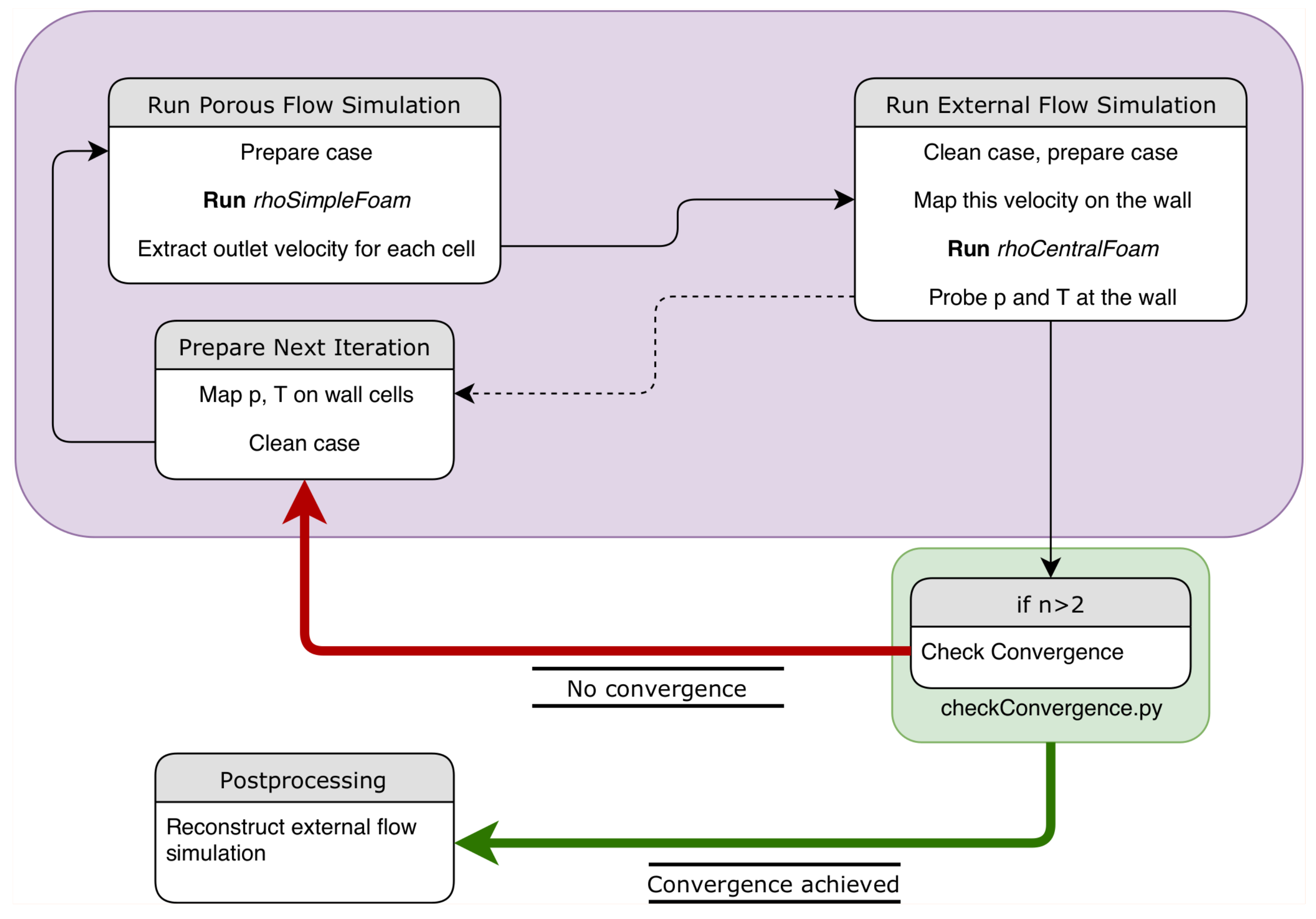
The explicit coupling process involves exchange of the variables at the interface of the two domains of computation and is implemented using python and shell scripts. Both the solvers are run in a serial manner and the relevant variables are mapped at the end of each independent run to be used by the other solver. The velocities obtained at the outlet of the porous region are mapped onto the wall of the re-entering object/vehicle, in this case the surface of the cylinder. To do so, the pressure and temperature on the wall from external free-stream domain computation are first mapped back onto the outlet of the porous only domain. Thus, the variables (velocity, pressure, temperature) are exchanged at the interface between external and porous domains after each complete solution of the solvers. This procedure is repeated until convergence is achieved. Convergence checking is done for pressure values at three locations (0, 45 and 90 angles along the cylinder surface). Convergence is achieved when the change in the probed pressure values in all three locations is less than the specified convergence criterion. The convergence can also be checked for temperature or velocity instead of pressure and the number of probes can also be increased if desired. This coupling procedure is shown as a flowchart in Figure 2.
3.2. Computational Setup
For the presented results, the geometry for the computations is a 12 inch diameter 2D axi-symmetrical cylinder with a 5 mm layer of porous coating of UHTC-8 material [13] across the cylinder’s surface. The relevant material properties for the UHTC-8 material are presented in Table 2 below. The computational domains for each of the solvers are independent, as is evident from the previous discussion. This is shown in the Figure 3 below. For this geometry, a structured mesh was created, and mesh independence studies were carried out. In the external domain, the cell size near the wall was chosen to be at least equal to the mean free path for the initial conditions of the computations. The mean free path calculation is based on variable hard sphere (VHS) model. For the external flow domain fully structured mesh with 192,004 elements (126,504 qudrangles and 65,500 hexahedra) and for the porous domain mesh 27,478 elements (18,718 qudrangles and 8760 hexahedra) were created using the open source meshing tool Gmsh [34]. The common interface between the two domains comprised of 584 cell faces. The mesh is shown in Figure 4.
Argon flow is considered for both the domains to avoid dealing with the complex non-equilibrium reactions during the re-entry which the solvers rhoCentralFoam or rhoSimpleFoam cannot handle. The external flow was chosen to be Mach 10 and the coolant pressure for porous computations was varied for comparative analysis. The specific heats are calculated from the thermophysical model based on Joint Army Navy Air Force thermochemical data, popularly known as JANAF, and the viscosity is based on the Sutherland law. The Sutherland viscosity coefficients (for the form in Equation (2)) used for these computations are given below in Table 3. These coefficients are obtained by fitting the viscosity by power law for VHS model used by Lofthouse [30].
Since the UHTC considered in the present work is a conducting material, choosing a relatively small thickness of the porous layer creates room for the assumption that the porous domain remains at a fixed temperature. This temperature is taken from the fixed wall temperature boundary condition for the external flow computation. Additionally, for the coupled computations, the coolant is assumed to leave the cylinder wall normal to the surface and the corresponding boundary condition is applied. Maxwell velocity slip [35] and Smoluchowski temperature jump [36] conditions with accommodation coefficient of unity are imposed on the cylinder surface to account for the rarefied flow conditions wherever applicable. These initial conditions are summarised in Table 4. For these conditions, the flow will be laminar; hence, no turbulence model is implemented.
4. Results and Discussion
The transpiration cooling affects the flow in the immediate vicinity of the wall, leading to reduction in the heat flux received by the re-entering cylinder’s surface. The external flow is deflected slightly from the cylinder surface when transpiration cooling is employed, and this is evident from the velocity contours. The relatively small coolant velocities also affect the shock formation away from the cylinder as compared to the non-transpiration case. The velocity contours near the cylinder wall are shown in the Figure 5 below; it should be noted the coolant velocity is very small compared to the external flow velocity.
4.1. Variation in Coolant Plenum Pressure
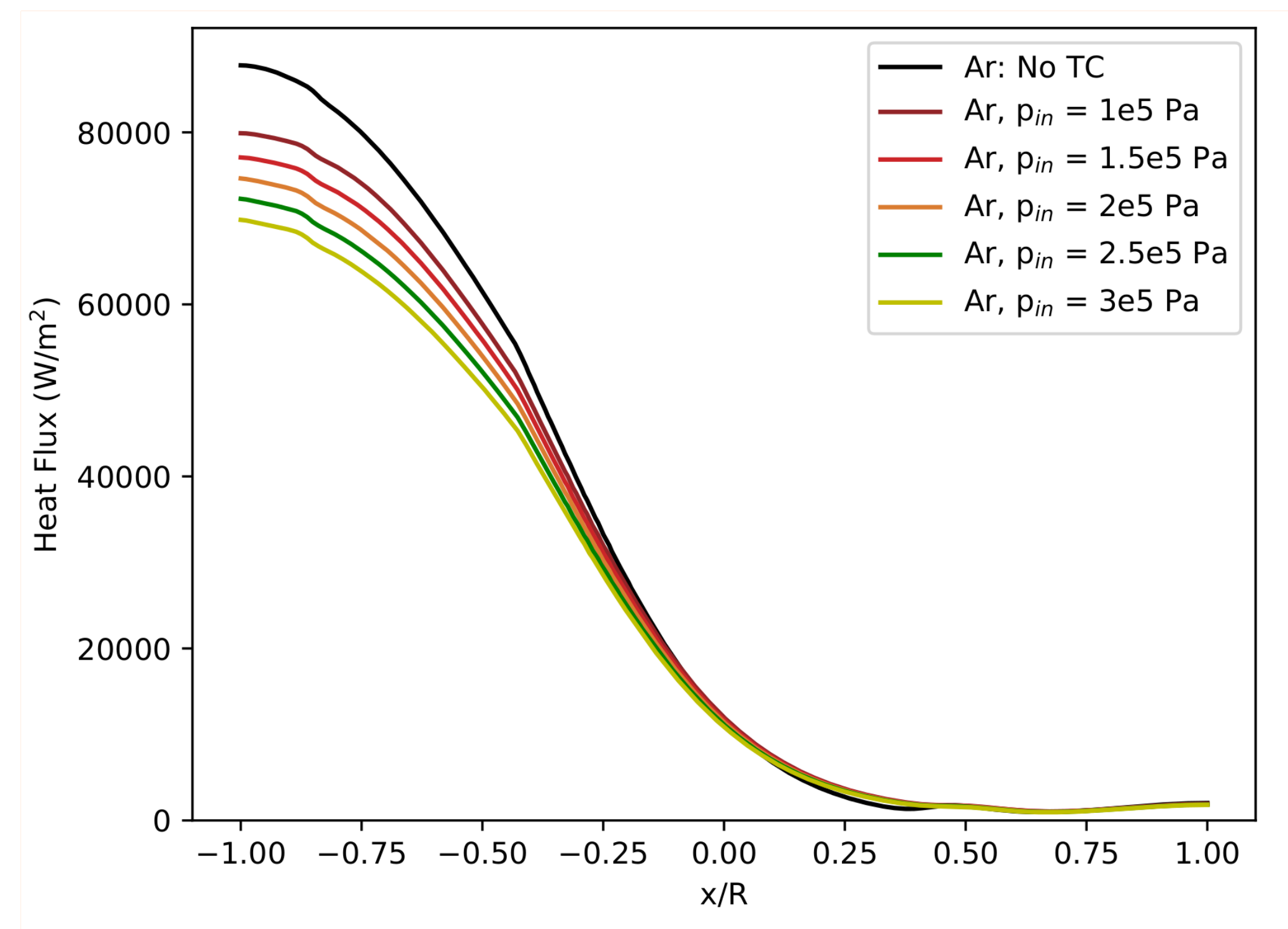
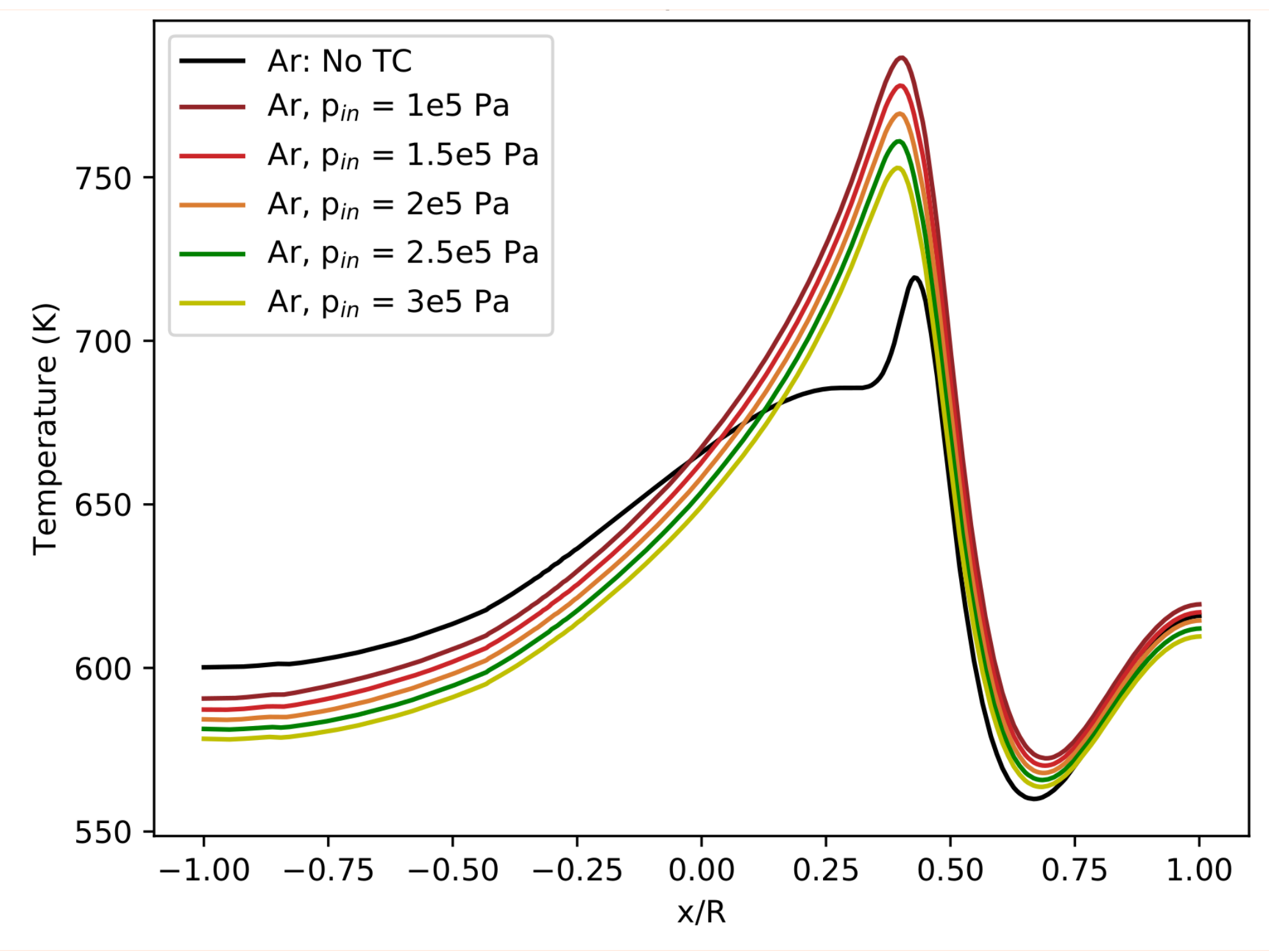
Coolant plenum pressure is varied in steps of 0.5 bar, and the corresponding results are plotted in Figure 6, Figure 7 and Figure 8. In these plots, x represents the distance from the upstream direction and R is the radius of the cylinder. Heat flux reduction is observed in the upstream direction, and although the reduction reduces downstream, the magnitude of heat flux itself reduces. Whereas the wall temperature shows distinct drop in the upstream direction as compared to the non-transpiration case, the difference is inverted further downstream along the cylinder surface and is maximum near x/R = 0.4 mark. A trend noted here is that both drop in upstream wall temperature and heat flux increase with increased coolant pressure. These trends are analogous to the coolant velocity obtained along the wall with varying plenum pressure, as shown in Figure 8. The peak heat flux in each case is tabulated in Table 5.
As observed here, the drop in incoming convective heat flux increases distinctly with an increase in coolant pressure, confirming that the coolant pressure is one of the important design variables for a transpiration-cooling-based TPS. The deviation in temperature along the wall from the initial fixed temperature is due to the rarefied fluid flow conditions because of the implemented Smoluchowski temperature jump boundary condition. The velocity profile along the wall shows a distinct pattern that is directly dependent on the coolant pressure.
4.2. Variation in Initial Fixed Wall Temperature
Additionally, the fixed wall temperature and the fixed porous domain temperature were also varied. The fixed porous domain temperature was chosen to be the same as the initial cylinder wall temperature. While during the coupled simulations, the wall temperature obtained through application of temperature jump condition was mapped on the porous geometry outlet in each iteration, the porous domain temperature remained fixed at the initial value.
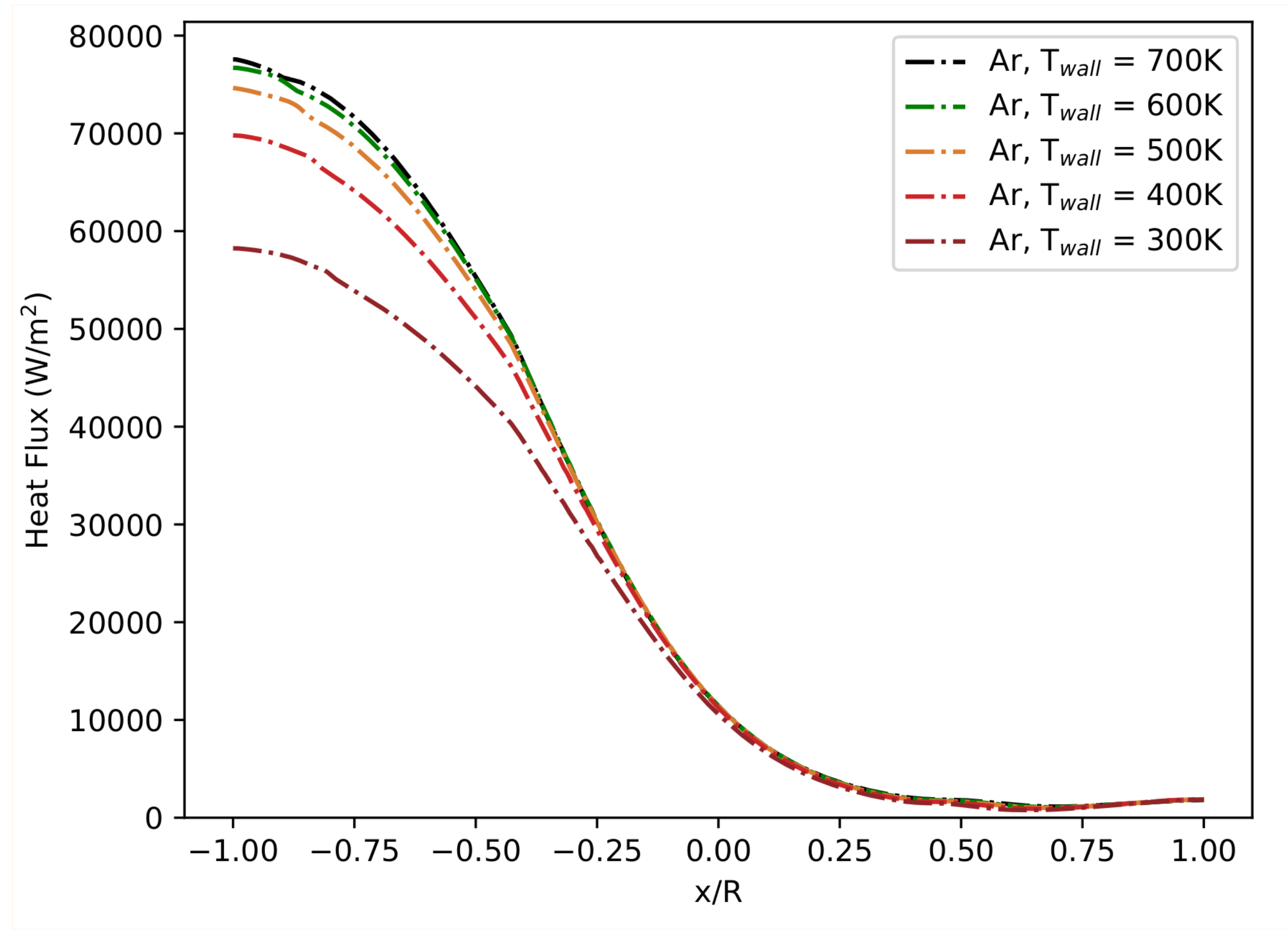
Results obtained for different values of T are shown in Figure 9, Figure 10 and Figure 11. All the the other initial conditions were as mentioned in Table 4. The peak heat flux in each case is tabulated in Table 6.
As observed from these computations, the choice of higher wall temperature for numerical computations constrains the drop in incoming heat flux.
There are other influencing factors, such as the Mach number of the flow, cylinder curvature and free flow, which are currently under investigation. Moreover, while this study involved a 2D, axial-symmetrical cylinder geometry, the numerical procedure may be extended to 3D geometries with appropriate modifications while considering the computational resources needed. The extended results of the ongoing study and the application of the methodology to 3D cases will be the subjects of future publications.
5. Conclusions
High speed argon flow over a 2D axi-symmetrical cylinder was simulated using a newly developed loose, explicit and iterative coupling procedure. The coupling is done at the interface of the external flow and the internal porous flow, both of which are independently solved. The results indicate that the use of transpiration cooling translates into a distinct drop in the heat flux within a range of 10% to 22%, when coolant pressure is varied between 1 and 3 bar. Results also show the strong influence of the wall temperature. Variations in initial fixed wall temperature in the range of 300 to 1000 K may result in 33% to 10% heat flux drop, stressing the importance of this parameter for the correct and appropriate modelling of this kind of system. This work shows the potential of the transpiration cooling method to be employed as part of the thermal protection strategy for re-entry vehicles, and the developed coupling procedure shows a promising way to simulate such a system.
For future work, the temperature in the porous region can be derived from the mapped wall temperature instead of fixing it to a certain value. Additionally, other variables involved—those different from the ones considered here—can be taken into account for at more realistic and complete modelling.
Current and future work will also involve the exploitation of the obtained results to develop and implement low fidelity meta-modelling approaches to design transpiration-cooling-based thermal protection systems.
Author Contributions
Investigation and writing—original draft preparation, D.B.; supervision and writing—review and editing, E.M. All authors have read and agreed to the published version of the manuscript.
Funding
This research received no external funding.
Acknowledgments
Results for this project have been obtained using the EPSRC funded ARCHIE-WeSt High Performance Computer (www.archie-west.ac.uk). EPSRC grant number EP/K000586/1.
Conflicts of Interest
The authors declare no conflict of interest.
References
- Kuzenov, V.V.; Ryzhkov, S.V. Approximate calculation of convective heat transfer near hypersonic aircraft surface. J. Enhanc. Heat Transf. 2018, 25, 181–193. [Google Scholar] [CrossRef]
- Di Giorgio, S.; Quagliarella, D.; Pezzella, G.; Pirozzoli, S. An aerothermodynamic design optimization framework for hypersonic vehicles. Aerosp. Sci. Technol. 2019, 84, 339–347. [Google Scholar] [CrossRef]
- De Cesare, M.; Savino, L.; Ceglia, G.; Alfano, D.; Di Carolo, F.; French, A.; Rapagnani, D.; Gravina, S.; Cipullo, A.; Del Vecchio, A.; et al. Applied radiation physics techniques for diagnostic evaluation of the plasma wind and thermal protection system critical parameters in aerospace re-entry. Prog. Aerosp. Sci. 2020, 112, 100550. [Google Scholar] [CrossRef]
- Pavlosky, J.E.; Leger, L.G.S. Apollo Experience Report—Thermal Protection Subsystem; Technical Report NASA TN D-7564; National Aeronautics and Space Administration; Lyndon B. Johnson Space Center Houston: Houston, TX, USA, 1974; p. 77058.
- Heppenheimer, T.A. Facing the Heat Barrier: A History of Hypersonics; NASA SP (Series), 4232; National Aeronautics and Space Administration, NASA History Division, Office of External Relations: Washington, DC, USA, 2007.
- Camarda, C.J.; Glass, D.E. Thermostructural Applications of Heat Pipes for Cooling Leading Edges of High-Speed Aerospace Vehicles; Technical Report; NASA: Hampton, VA, USA, 1992; pp. 291–318.
- Bouilly, J.M.; Dariol, L.; Leleu, F. Ablative Thermal Protections for Atmospheric Entry. An Overview of Past Missions and Needs for Future Programmes. In Thermal Protection Systems and Hot Structures; ESA Special Publication: Noordwijk, The Netherlands, 2006; Volume 631, p. 26. [Google Scholar]
- Ronquillo, L.; Williams, C. Thermal Protection System for the Space Shuttle External Tank. J. Therm. Insul. 1984, 7, 228–250. [Google Scholar] [CrossRef]
- Atkins, K.L.; Brownlee, D.E.; Duxbury, T.; Yen, C.; Tsou, P.; Vellinga, J.M. STARDUST: Discovery’s InterStellar dust and cometary sample return mission. In Proceedings of the 1997 IEEE Aerospace Conference 1997, Snowmass at Aspen, CO, USA, 13 February 1997; 1997; Volume 4, pp. 229–245. [Google Scholar]
- He, F.; Wang, J.; Xu, L.; Wang, X. Modeling and simulation of transpiration cooling with phase change. Appl. Therm. Eng. 2013, 58, 173–180. [Google Scholar] [CrossRef]
- Su, Y.; Davidson, J. Modeling Approaches to Natural Convection in Porous Media, 1st ed.; Springer International Publishing: Cham, Switzerland, 2015. [Google Scholar]
- Prokein, D.; Boehrk, H.; von Wolfersdorf, J. Analysis of Anisotropy Effects for Transpiration Cooled CMC Leading Edges using OpenFOAM. In Proceedings of the 20th AIAA International Space Planes and Hypersonic Systems and Technologies Conference, Glasgow, Scotland, 6–9 July 2015. [Google Scholar]
- Ifti, H.S.; Hermann, T.; McGilvray, M. Flow Characterisation of Transpiring Porous Media for Hypersonic Vehicles. In Proceedings of the 22nd AIAA International Space Planes and Hypersonics Systems and Technologies Conference, Orlando, FL, USA, 17–19 September 2018. [Google Scholar]
- Ewenz Rocher, M.; McGilvray, M.; Hermann, T.A.; Ifti, H.S.; Hufgard, F.; Eberhart, M.F.; Meindl, A.; Loehle, S.; Giovannini, T.; Veperre, L.J.; et al. Testing a Transpiration Cooled Zirconium-Di-Boride sample in the Plasma Tunnel at IRS. In Proceedings of the AIAA Scitech 2019 Forum, San Diego, CA, USA, 7–11 January 2019. [Google Scholar]
- Lie, K.A.; Krogstad, S.; Ligaarden, I.S.; Natvig, J.R.; Nilsen, H.M.; Skaflestad, B. Open-source MATLAB implementation of consistent discretisations on complex grids. Comput. Geosci. 2012, 16, 297–322. [Google Scholar] [CrossRef] [Green Version]
- Flemisch, B.; Darcis, M.; Erbertseder, K.; Faigle, B.; Lauser, A.; Mosthaf, K.; Müthing, S.; Nuske, P.; Tatomir, A.; Wolff, M.; et al. DuMux: DUNE for multi-phase,component,scale,physics,… flow and transport in porous media. Adv. Water Resour. 2011, 34, 1102–1112. [Google Scholar] [CrossRef]
- Hammond, G.E.; Lichtner, P.C.; Mills, R.T. Evaluating the performance of parallel subsurface simulators: An illustrative example with PFLOTRAN. Water Resour. Res. 2014, 50, 208–228. [Google Scholar] [CrossRef] [Green Version]
- Raeini, A.Q.; Blunt, M.J.; Bijeljic, B. Modelling two-phase flow in porous media at the pore scale using the volume-of-fluid method. J. Comput. Phys. 2012, 231, 5653–5668. [Google Scholar] [CrossRef]
- Tomin, P.; Lunati, I. Hybrid Multiscale Finite Volume method for two-phase flow in porous media. J. Comput. Phys. 2013, 250, 293–307. [Google Scholar] [CrossRef]
- Horgue, P.; Soulaine, C.; Franc, J.; Guibert, R.; Debenest, G. An open-source toolbox for multiphase flow in porous media. Comput. Phys. Commun. 2015, 187, 217–226. [Google Scholar] [CrossRef] [Green Version]
- Weller, H.G.; Tabor, G.; Jasak, H.; Fureby, C. A tensorial approach to computational continuum mechanics using object-oriented techniques. Comput. Phys. 1998, 12, 620–631. [Google Scholar] [CrossRef]
- Heyns, J.; Oxtoby, O. Modelling high-speed viscous flow in OpenFOAM. In Proceedings of the 9th South African Conference on Computational and Applied Mechanics, SACAM 2014, Somerset West, South Africa, 14–16 January 2014. [Google Scholar]
- Lachaud, J.; Mansour, N.N. Porous-Material Analysis Toolbox Based on OpenFOAM and Applications. J. Thermophys. Heat Transf. 2014, 28, 191–202. [Google Scholar] [CrossRef]
- Prokein, D.; von Wolfersdorf, J. Numerical simulation of turbulent boundary layers with foreign gas transpiration using OpenFOAM. Acta Astronaut. 2019, 158, 253–263. [Google Scholar] [CrossRef]
- Khan, M.B.; Iqbal, N.; Haider, Z. Transpiration Cooling Assisted Ablative Thermal Protection of Aerospace Substructures; Trans Tech Publications Ltd.: Stafa-Zurich, Switzerland, 2010; Volume 442, pp. 34–40. [Google Scholar]
- Liu, Y.Q.; Jiang, P.; Xiong, Y.B.; Wang, Y.P. Experimental and numerical investigation of transpiration cooling for sintered porous flat plates. Appl. Therm. Eng. 2013, 50, 997–1007. [Google Scholar] [CrossRef]
- Boehrk, H. Transpiration Cooling at Hypersonic Flight - AKTiV on SHEFEX II. In Proceedings of the 11th AIAA/ASME Joint Thermophysics and Heat Transfer Conference, Atlanta, GA, USA, 16–20 June 2014. [Google Scholar]
- Shen, L.; Wang, J.; Dong, W.; Peng, J.; Qu, D.; Chen, L. An experimental investigation on transpiration cooling with phase change under supersonic condition. Appl. Therm. Eng. 2016, 105, 549–556. [Google Scholar] [CrossRef]
- Huang, G.; Zhu, Y.H.; Liao, Z.; Ouyang, X.L.; Jiang, P. Experimental investigation of transpiration cooling with phase change for sintered porous plates. Int. J. Heat Mass Transf. 2017, 114, 1201–1213. [Google Scholar] [CrossRef]
- Lofthouse, A.J. Nonequilibrium Hypersonic Aerothermodynamics Using the Direct Simulation Monte Carlo And Navier-Stokes Models. Ph.D. Thesis, University of Michigan, Ann Arbor, MI, USA, 2008. [Google Scholar]
- Kurganov, A.; Tadmor, E. New high-resolution central schemes for nonlinear conservation laws and convection–diffusion equations. J. Comput. Phys. 2000, 160, 241–282. [Google Scholar] [CrossRef] [Green Version]
- Kurganov, A.; Noelle, S.; Petrova, G. Semidiscrete central-upwind schemes for hyperbolic conservation laws and Hamilton–Jacobi equations. SIAM J. Sci. Comput. 2001, 23, 707–740. [Google Scholar] [CrossRef] [Green Version]
- Whitaker, S. The Forchheimer equation: A theoretical development. Transp. Porous Media 1996, 25, 27–61. [Google Scholar] [CrossRef]
- Geuzaine, C.; Remacle, J.F. Gmsh: A 3-D finite element mesh generator with built-in pre- and post-processing facilities. Int. J. Numer. Methods Eng. 2009, 79, 1309–1331. [Google Scholar] [CrossRef]
- Maxwell, J.C. VII. On stresses in rarified gases arising from inequalities of temperature. Philos. Trans. R. Soc. Lond. 1879, 170, 231–256. [Google Scholar]
- Smoluchowski von Smolan, M. Ueber wärmeleitung in verdünnten gasen. Ann. Der Phys. 1898, 300, 101–130. [Google Scholar] [CrossRef] [Green Version]
Figure 1.
Schematic of transpiration cooling.

Figure 2.
Flowchart of the coupling procedure.

Figure 3.
Geometric details (not to scale).

Figure 4.
Meshing for individual domains with close-up of upstream mesh for porous domain.

Figure 5.
Velocity contours in the flow field near cylinder wall.

Figure 6.
Heat flux distribution for Mach 10 argon flow when coolant plenum pressure is varied (TC = transpiration cooling).
Figure 6.
Heat flux distribution for Mach 10 argon flow when coolant plenum pressure is varied (TC = transpiration cooling).

Figure 7.
Temperature variation along wall for Mach 10 argon flow when coolant plenum pressure is varied (TC = transpiration cooling).
Figure 7.
Temperature variation along wall for Mach 10 argon flow when coolant plenum pressure is varied (TC = transpiration cooling).

Figure 8.
Coolant velocity variation along wall for Mach 10 argon flow when coolant plenum pressure is varied.
Figure 8.
Coolant velocity variation along wall for Mach 10 argon flow when coolant plenum pressure is varied.

Figure 9.
Heat flux distribution for Mach 10 argon flow when wall and porous domain temperature is varied.
Figure 9.
Heat flux distribution for Mach 10 argon flow when wall and porous domain temperature is varied.

Figure 10.
Temperature variation along wall for Mach 10 argon flow when wall and porous domain temperature is varied.
Figure 10.
Temperature variation along wall for Mach 10 argon flow when wall and porous domain temperature is varied.

Figure 11.
Coolant velocity variation along wall for Mach 10 argon flow when wall and porous domain temperature is varied.
Figure 11.
Coolant velocity variation along wall for Mach 10 argon flow when wall and porous domain temperature is varied.


Table 1.
Verification of suitability of solvers for argon flow over the cylinder.
| External Flow Solution | |||
|---|---|---|---|
| Q (kW/m) | Deviation | ||
| rhoCentralFoam | Work in [30] | ||
| Maxwell slip | 88.95 | 89.14 | −0.21% |
| No slip | 89.88 | 89.84 | 0.03% |
| Porous Flow Solution | |||
| Plenum pressure | Outlet velocity (m/s) | Deviation | |
| p (bar) | rhoSimpleFoam | Work in [13] | |
| 3 | 0.156 | 0.155 | 0.65% |
| 5 | 0.442 | 0.441 | 0.23% |
Table 2.
Ultra high temperature ceramic (UHTC) material properties for UHTC-8 [13].
Table 2.
Ultra high temperature ceramic (UHTC) material properties for UHTC-8 [13].
| Quantity | Value | Unit |
|---|---|---|
| Darcy coefficient, | m | |
| Forchheimer coefficient, | m |
Table 3.
Fitted Sutherland viscosity coefficients used.
| Quantity | Value | Unit |
|---|---|---|
| Sutherland constant, A | kg/msK | |
| Sutherland temperature, | 200 | K |
Table 4.
Initial configuration for computations using argon as fluid for Mach 10 flow.
| Quantity | Value | Unit |
|---|---|---|
| Free-stream temperature, | 200 | K |
| Free-stream pressure, | 5.853 | Pa |
| Free-stream velocity, | 2636.78 | m/s |
| Wall temperature, | 500 | K |
| Number density, n | m | |
| Overall Knudsen number, | 0.002 | - |
Table 5.
Change in the incoming heat flux for Mach 10 argon flow with change in the coolant pressure (TC = transpiration cooling).
Table 5.
Change in the incoming heat flux for Mach 10 argon flow with change in the coolant pressure (TC = transpiration cooling).
| p (Bar) | Q (kW/m) | Q | |
|---|---|---|---|
| No TC | TC | ||
| 1 | 88.95 | 79.90 | −10.17% |
| 1.5 | 77.09 | −13.33% | |
| 2 | 74.64 | −16.09% | |
| 2.5 | 72.27 | −18.75% | |
| 3 | 69.83 | −21.50% | |
Table 6.
Change in the incoming heat flux with changes in the wall and porous domain temperature (TC = transpiration cooling).
Table 6.
Change in the incoming heat flux with changes in the wall and porous domain temperature (TC = transpiration cooling).
| T (K) | Q (kW/m) | Q | |
|---|---|---|---|
| No TC | TC | ||
| 700 | 86.53 | 77.57 | −10.36% |
| 600 | 87.14 | 76.71 | −11.97% |
| 500 | 87.79 | 74.64 | −14.98% |
| 400 | 87.76 | 69.80 | −20.46% |
| 300 | 86.58 | 58.24 | −32.73% |
© 2020 by the authors. Licensee MDPI, Basel, Switzerland. This article is an open access article distributed under the terms and conditions of the Creative Commons Attribution (CC BY) license (http://creativecommons.org/licenses/by/4.0/).
Share and Cite
MDPI and ACS Style
Bandivadekar, D.; Minisci, E. Modelling and Simulation of Transpiration Cooling Systems for Atmospheric Re-Entry. Aerospace 2020, 7, 89. https://doi.org/10.3390/aerospace7070089
AMA Style
Bandivadekar D, Minisci E. Modelling and Simulation of Transpiration Cooling Systems for Atmospheric Re-Entry. Aerospace. 2020; 7(7):89. https://doi.org/10.3390/aerospace7070089
Chicago/Turabian StyleBandivadekar, Deep, and Edmondo Minisci. 2020. "Modelling and Simulation of Transpiration Cooling Systems for Atmospheric Re-Entry" Aerospace 7, no. 7: 89. https://doi.org/10.3390/aerospace7070089
Note that from the first issue of 2016, this journal uses article numbers instead of page numbers. See further details here.