
CFD Investigation into Flow Characteristics of a Special Splash Lubrication in Light Helicopters

College of Mechanical and Electrical Engineering, Central South University, Changsha 410083, China
*
Author to whom correspondence should be addressed.
Aerospace 2022, 9(9), 482; https://doi.org/10.3390/aerospace9090482
Submission received: 27 June 2022
/
Revised: 25 August 2022
/
Accepted: 26 August 2022
/
Published: 29 August 2022
(This article belongs to the Section Aeronautics)
Abstract
:Lubricating oil flow characteristics are the primary concern in the main reducer of light helicopters. To improve the lubricating performance of the main reducer, a special lubrication system is innovatively constructed by adding two oil-guiding tubes to the hub of the output gear, and the influence of the oil-guiding tubes is investigated through CFD (computational fluid dynamics) techniques. A CFD model of the gearbox integrated with the VOF (volume of fluid) technique was established to explore the flow characteristics of the oil–air two-phase flow inside the gearing system. To validate the proposed CFD model, a specialized testing rig is devised and manufactured to examine the features of oil distribution. The effects of the structure parameters of the oil-guiding tubes and operating conditions on the lubrication performance are explored. Comparing experimental and numerical findings reveals that the inner diameter of the oil-guiding tube and the rotational speed of the driven gear have a significant influence on the lubrication performance. In contrast, the length of the installation end of the oil-guiding tube, its angle, and the oil-immersion depth show little impact.
1. Introduction
In the intermediate or tail gearbox of light helicopters with a low rotational speed, the lubrication system is among the most crucial components. The lubrication and cooling performance of gears directly affect the operating performance and service life of the transmission system [1].
With the development of the CFD technique, a deep understanding of the detailed flow field characteristics of gearing systems can be achieved [2,3,4]. Moshammer et al. [5] developed and validated a CFD approach for simulating the flow field inside a cylindrical gearbox when gears splashed oil at various tooth profiles and rotation rates. Li et al. [6] developed a two-dimensional CFD approach to explore the influence of oil quantity, oil physical properties, and gear speed on oil distribution characteristics within a cylindrical splash lubrication gearbox. Hu et al. [7] presented a CFD approach for the splash lubrication of a helicopter’s main gearbox to investigate the effects of various operating circumstances on churning power losses. Jiang et al. [8] constructed a CFD framework for predicting the impact of the geometrical parameters of an oil guide device on the splash lubrication capacity of a helicopter’s main gearbox. The authors [9] further improved the model to analyze the effects of various dynamic flying attitudes on the churning power losses and splash lubrication effectiveness. Experiments were used to validate the practicality of their simulation methodologies. Liu et al. [10] evaluated the oil distribution and the churning power losses of a gear transmission mechanism through a CFD model and showed good consistency with the test findings. Gorla et al. [11,12] investigated the effect of gear geometrical characteristics and working conditions on the power loss of gear transmission through CFD analysis. Concli et al. [13,14,15,16] further estimated the churning loss of the planetary gear gearbox under different gear parameters and working conditions (oil temperature, oil level, rotating speed) by simulating the movement behavior of the air–oil mixture. Kolekar et al. [17] developed a specialized test bench comprising a cylindrical box and a single spur gear for the purpose of determining the effect of lubricating oil qualities on churning power loss. Yin et al. [18,19] studied the effect of various types of oil-guiding cylinder structures on the splash lubrication effectiveness in a light helicopter gearbox employing a CFD model, and the numerical results accorded well with the experimental findings. Peng et al. [20] developed a CFD model for simulating lubrication flow within a vehicle axle housing. The effects of various operational conditions on churning power loss were evaluated. The numerical calculations’ conclusions for oil dispersion were very consistent with the experimental observations. Based on a thermal-fluid coupling modeling technique, Lu et al. [21] studied the lubrication and temperature features of a gear system under the condition of splash lubrication. The numerical findings showed that the roller rotation direction and gravity influenced the oil volume fraction distribution law. To enhance the oil jet lubrication performance of the aviation gearbox, Dai et al. [22,23,24,25] developed CFD models for various types of gears to determine the ideal oil nozzle layout. The effects of jet nozzle arrangement factors on lubrication capacity, including the position, angle, and number, have been investigated and optimized. Fondelli et al. [26,27] investigated oil-jet losses and the resisting torque induced by jet lubrication utilizing a CFD model of high-speed gears and a rotating test apparatus equipped with high-speed visualizations.
The aforementioned research mainly focused on the traditional lubrication methods. However, the light helicopter is featured with a compact structure, small volume, and low weight, that has high requirements to the main reducer. The common splash or jet lubrication method are not applicable anymore. Therefore, this paper describes a special splash lubrication method. Instead of being directly immersed in the oil sump, the meshing gear pair in the main gearbox is lubricated through the oil-guiding tubes to steer the oil flow from the oil sump to the gear surface, as illustrated in Figure 1. This paper aims to evaluate the impact of the geometry parameters of oil-guiding tubes and working conditions on the lubrication and cooling performance by leveraging with the CFD approach. Moreover, a specialized splash lubrication testing bench is set up for the purpose of validating the proposed numerical analysis’s practicality. It will provide the design and manufacturing principles for the main gearbox in light helicopters.
2. Methodology
2.1. Governing Equations
Calculating the characteristics of the gearbox’s lubricating flow field without taking the influence of temperature into account involves the use of mass and momentum conservation equations.
a. Mass conservation equation:
where ρ represents the fluid density. u, v, and w denote x, y, and z velocity components, correspondingly.
b. Momentum conservation equation:
where Fbx, Fby and Fbz are mass force components acting on the fluid micro-element body in the x, y, and z directions, respectively, and p is the tension component of the fluid internal stress.
2.2. Multiphase Flow Model
Under the condition of splash lubrication with the oil-guiding tube, the flow field in the gearbox is a typical gas–liquid two-phase flow model. The lubricating oil is the primary phase, while air is the secondary phase. The Volume of Fluid model is mainly used to simulate the interface change process of various incompatible fluids [28]. In the model, the fluid interface is tracked by solving the continuous equation, and the location of the interface is determined by finding the sharply changing point in the volume component.
The proportion of oil and air in the total fluid calculation domain is represented by the volume ratio, and the sum of the volume ratio of the two is equal to 1.
where α1 represents the volume rate of lubricating oil and α2 represents the volume rate of air.
2.3. Turbulence Model
In the CFD calculation, the choice of turbulence model largely determines the accuracy of the simulation results. The RNG k-ε model [29] has certain advantages when simulating rotation and swirling flow, and its transport equation is:
where Gk represents the turbulent kinetic energy production term caused by the average velocity gradient; Gb represents the turbulent kinetic energy k production term caused by buoyancy; YM represents the contribution of pulsation expansion incompressible turbulence; C1ε, C2ε, C3ε are empirical constants; σk, σε represents the Prandtl number corresponding to turbulent kinetic energy k and dissipation rate ε; and Sk and Sε are the source items defined by the user.
2.4. Numerical Method
The software utilized in this investigation is ANSYS Fluent 19.2. The following are the primary settings for numerical simulation in this study: the pressure-based solver with the time option set to transient is utilized and taking gravity into account; the VOF model is activated, and the primary phase is set to be air, the secondary phase to be lubricating oil, the implicit volume fraction formulation is selected, and implicit body forces are enabled; the energy module is turned off since the influence of temperature is not considered; the RNG k-epsilon model is used, and the near-wall treatment is considered as standard wall functions; the mesh motion technology is utilized to imitate the gear pair’s rotation; only wall boundary conditions are considered in this study, and they are all set to nonslip; the PISO (Pressure-Implicit with Splitting of Operators) algorithm is used in the solution method for pressure velocity coupling, and the gradient difference, the pressure term, and the momentum term are set to the least squares cell-based method, PRESTO, and second-order upwind, respectively; all residuals convergence criteria are set to 1 × 10⁻³; and the time step is in fixed mode and set to 2.5 × 10⁻⁵ s.
In this study, the lubricating oil flow rate in the meshing area is employed as the criterion for judging the lubrication effect of the oil-guiding tube. To obtain the lubricating oil flow data in the meshing area in the CFD simulation, a monitoring surface (shown in Figure 2) in the meshing area is created, and the Report Type is set to Mass Flow Rate, the Phase to Oil, and the recording interval to 10 steps.
2.5. Numerical Model and Grids
The objective of this study is to investigate the transient flow field characteristics in the light helicopter main gearbox and the lubricating oil flow rate at the gear-meshing area under the condition of the special splash lubrication. To simplify the model, remove all non-essential parts and retain only the essential parts related to splash lubrication, such as the main gearbox, driving gear, driven gear, output shaft, and oil-guiding tube. The simplified geometric model is shown in Figure 2. Since there are no gear teeth immersed in the lubricating oil under the studied working conditions, the gear teeth have no effect on the rotating drainage effect of the oil-guiding tube. To reduce the calculation load and shorten the calculation time, the gear teeth are removed to simplify the gear structure.
The structure of the main gearbox is complex, and the internal flow field changes drastically. Therefore, the use of unstructured tetrahedral meshes can better adapt to complex boundary conditions. The meshes around the gear surface and the oil-guiding tube were refined to enhance the simulation’s reliability. To ensure the computation results would not be affected by the number of grids, the grid independence was analyzed, as shown in Table 1. Taking the lubricating oil mean flow rate through the monitoring surface as the monitoring parameter, when the number of grids reaches around 4 million, continue to increase the number of grids, and the flow rate of the monitoring surface will hardly change, but the simulation calculation time will increase significantly. The final grid number of the entire watershed body is 3,885,689, which includes 797,851 nodes, as shown in Figure 3.
3. Experimental Validation
3.1. Test Rig
To demonstrate the viability of the CFD approach for simulating the splash lubrication flow field of the oil-guiding tube rotating drainage, a drainage splash lubrication test rig was established (see Figure 4).
The primary components of the test rig include servo drive motors, plum blossom couplings, test gearboxes, high-speed cameras, control systems, and test benches. The internal structure of the wheel box is shown in Figure 5. This test only observes the instantaneous distribution of lubricating oil inside the gearbox, so only the drive motor is used to control the speed of the output gear, and no input gear is set. Detachable oil-guiding tubes with threaded connections are installed on the gear spokes. An observation hole is placed on the side of the gearbox, which allows a high-speed camera to capture the flow characteristics of the lubricating oil inside the box at any given time.
3.2. Experimental Test
The density of the lubricating oil used in the test is 0.97 g/cm3, and the dynamic viscosity is 0.0075 N·s/m2. The rotating speed of the output gear speed is 600 r/min. The oil-immersion depth is defined as the distance between the lubricating oil level and the bottom surface of the gearbox’s inner wall. Several tests were carried out with different oil-immersion depths of 40 mm, 45 mm, and 50 mm. The simulation study carried out in this paper did not consider the influence of temperature, so the tests were carried out at the same ambient temperature and oil temperature, and the experimental time was only 5 min, to weaken the influence of temperature on the test results. The instantaneous distribution of lubricant in the tank is recorded by a Phantom VEO-410L high-speed camera.
To reflect the splash lubrication effect of the oil-guiding tube, this study employs the lubricating oil flow rate in the gear-meshing area as the evaluation criterion. Numerical simulation can measure the flow rate by setting a monitoring surface in the meshing area, but it is impossible to directly measure the lubricating oil flow rate at this position under the actual test conditions. As shown in Figure 6, under the conditions of different oil-immersion depths, there are differences in the morphology of the lubricating oil liquid column flowing out of the oil conduit recorded by the camera, and the corresponding CFD simulation shows similar differences. The reliability of the simulation model is indirectly verified by means of this qualitative comparison expressed in Figure 6.
As shown in Figure 6, the simulation results accord well with the test results, demonstrating the effectiveness of the simulation approach for the rotation drainage splash lubrication of the oil-guiding tube. The test results indicate that the lubricating oil can flow via the oil-guiding tube to the tooth surface of the output gear under the three oil-immersion depth settings. At the 40 mm immersion depth, all of the lubricating oil lies below the gear tooth surface; at the 45 mm immersion depth, a little lubricating oil rises along the inner wall of the box to the gear tooth surface. The increase in the oil-immersion depth influences the drainage effectiveness of the oil-guiding tube. There is a noticeable difference at the immersion depth of 50 mm, and a significant volume of lubricating oil climbs up to the gear tooth surface along the inner wall of the box; meanwhile, the amount of lubricating oil drained by the oil-guiding tube diminishes. The strong agitation of the lubricating oil weakens the drainage effect of the oil-guiding tube.
4. Results
During the operational process of the helicopter main gearbox, the driven gear drives the oil-guiding tubes to drain and splash the lubricating oil onto the gear surface. Therefore, the lubrication effect of the guide tube can be indirectly evaluated by measuring the lubricating oil flow rate at the gear-meshing area. Post-processing software can provide the volume fraction contour of lubricating oil that directly reflects the flow field characteristics. In Figure 7, the left 3D figures present the volume fraction contour of lubricating oil inside the main gearbox, and the right 2D figures illustrate the volume fraction contour of lubricating oil in the symmetry plane. The letter r denotes the count of rotations of the driven gear.
As demonstrated in the above simulation results, when R = 0.5 r, the lubricating oil is drained and splashed from the base of the main gearbox to the gear-meshing area through the oil-guiding tube, and in the meantime, the lubricating oil climbs along the inner wall of the gearbox under the action of centrifugal force. When R = 4.0 r, the internal flow field of the gearbox tends to be stable, and a large amount of lubricating oil is visible in the gear-meshing area.
From the above observations, it can be inferred that the geometrical and operating parameters of the oil-guiding tube are the primary elements impacting the lubricating oil flow rate in the gear-meshing area. The main geometrical parameters of the oil-guiding tube include the inner diameter, the angle, and the length of the installation end, as shown in Figure 8. In this study, the tube wall thickness t is held constant at 1 mm. The operating parameters of the oil-guiding tube mainly include gear rotation speed and oil-immersion depth. To examine the impact of the aforementioned factors on the drainage and splashing effects of the oil-guiding tube, multiple simulations with the various geometrical and operational parameters listed in Table 2 were conducted.
The change of lubricating oil flow rate in the gear-meshing area under the conditions of various inner diameters of the oil-guiding tube is depicted in Figure 9. It represents that the lubricating oil begins to appear in the gear-meshing area after the driven gear rotates 0.25 r. The peak flow rate occurs after the driven gear rotates half a circle or a full circle, that is, when the oil-guiding tube rotates to the gear-meshing position. It shows that the drainage effect of the oil-guiding tube is significant. After four rotations of the driven gear, the mean oil flow rates for d = 3 mL, 5 mL, and 7 mL are 4.8 g/s, 9.9 g/s, and 18.4 g/s, correspondingly. The observations indicate that the oil flow rate in the gear-meshing area is positively related to the inner diameter of the oil-guiding tube, and that modifying the inner diameter of the tube may drastically alter the oil flow rate.
Figure 10 depicts the lubricating oil flow rate in the gear-meshing area with different conditions of installation end lengths of the oil-guiding tube. The mean flow rates of L = 12 mm, 15 mm, and 18 mm are 18.4 g/s, 17.2 g/s, and 15.4 g/s, respectively. The lubricating oil flow rate in the gear-meshing area is slightly reduced. This is due to extending the installation end length of the oil-guiding tube, resulting in an increase in the lubricating oil’s climbing height. It is not favorable to increase the lubricating oil flow in the gear-meshing area.
The variation of the lubricating oil flow rate in the gear-meshing area under the conditions of different angles of the oil-guiding tube is represented in Figure 11. For oil-guiding tubes with different angles, the corresponding lubricating oil flow curves have a high degree of overlap. The average flow rate of θ = 70°, 90°, and 110° are 17.6 g/s, 18.4 g/s, and 18.7 g/s, correspondingly. This indicates that when the oil-guiding tube is fully immersed in the lubricating oil, the change in the angle of the oil-guiding tube has little impact on the lubricating oil flow rate in the gear-meshing area.
With various driven gear speeds, the lubricating oil flow rate in the gear-meshing area can be seen in Figure 12 under the action of the oil-guiding tube. The average flow rates of V = 400 r/min, 600 r/min, and 800 r/min are 11.6 g/s, 18.4 g/s, and 28.9 g/s, respectively. The lubricating oil flow rate in the gear-meshing area has increased significantly. It can be deduced from this that increasing the rotational speed of the driven gear can improve the drainage effect of the oil-guiding tube, leading to a significant increase in the amount of lubricating oil that flows through the gear-meshing area.
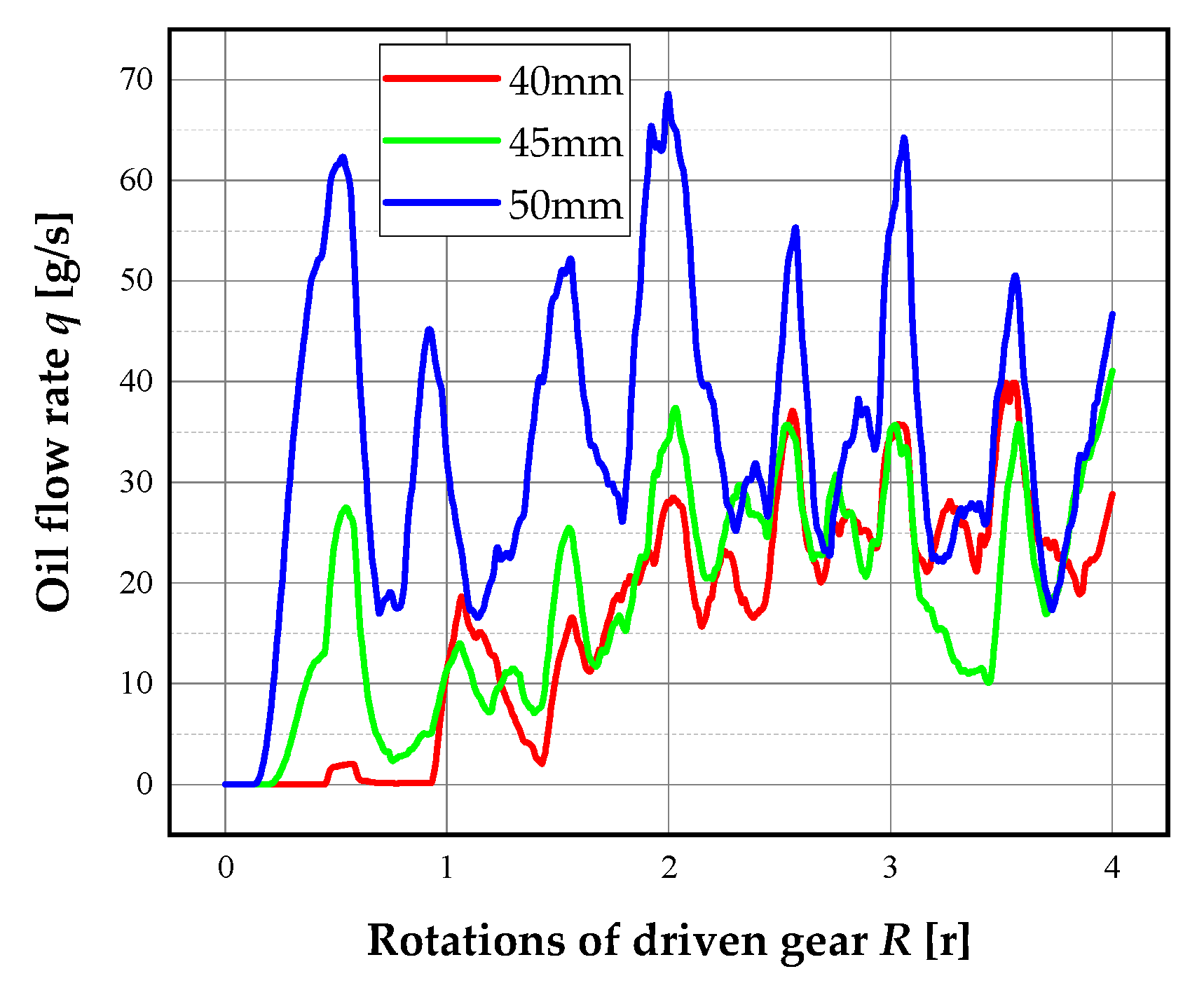
The amount of lubricating oil that flows through the gear-meshing area under the action of the oil-guiding tube can be seen in Figure 13, and it varies according to the depth of oil immersion. The mean flow rates of l = 40 mm, 45 mL, and 50 mm are 16.4 g/s, 18.4 g/s, and 34.4 g/s. The lubricating oil flow rate of the gear-meshing area l = 45 mm is slightly higher than l = 40 mm. However, the lubricating oil flow rate of the gear-meshing area at l = 50 mm is abnormally increased compared to l = 45 mm. Combined with the previous verification test, it can be learned that due to the increase in the oil-immersion depth, a huge quantity of lubricating oil rises to the gear surface along the inner wall of the gearbox under the action of centrifugal force. As a result, the abnormal increase in the lubricating oil flow rate in the gear-meshing area has nothing to do with the drainage function of the guide tube. Therefore, it is possible to draw the conclusion that raising the oil-immersion depth within a particular range can result in a modest improvement in the drainage effect produced by the oil-guiding tube. On the other hand, excessive oil immersion will cause a significant quantity of lubricating oil to climb to the surface of the gear, which will increase the churning power loss. This is a situation that must be avoided.
5. Conclusions
In this study, a CFD approach is used to evaluate how the lubrication performance is affected by the geometrical parameters of the oil-guiding tube and the working conditions of the main reducer. The CFD approach makes it possible to obtain information on the oil distribution features within the gearbox. As a special splash lubrication method, the numerical results show that the oil-guiding tubes can effectively steer the oil from the oil bath at the bottom of the main reducer to the gear surface. In addition, lubrication experiments have been performed on the specialized splash lubrication test bench to validate the proposed numerical method’s effectiveness. The principal conclusions are as follows.
Firstly, without compromising the gear strength and changing the wall thickness of the oil-guiding tubes, increasing the inner diameter of the oil-guiding tubes greatly enhances the oil supply rate in the gear-meshing area. Secondly, the oil supply rate in the gear-meshing area is somewhat reduced by the lengthening of the installation end of the oil-guiding tubes. Thirdly, regarding the oil-guiding tubes that are totally submerged, an increase in their angle has a marginal effect on the amount of oil that flows through the area where the gears mesh. Fourthly, elevating the output gear’s rotational speed will enhance the churning effect of the oil-guiding tube, leading to a significant increase in the oil supply rate in the gear-meshing area. Last but not least, the oil supply rate in the gear-meshing area grows as the tube oil-immersion depth increases in a certain range.
Future work will investigate the impact of oil temperature and helicopter flight attitude on the splash lubrication performance of the oil-guide tube, which will be more compatible with numerical simulations and actual conditions.
Author Contributions
Conceptualization, H.L. and Y.D.; data curation, H.L. and X.Z.; formal analysis, Y.D.; funding acquisition, Y.D.; investigation, X.Z.; methodology, H.L.; project administration, Y.D.; resources, J.J.; software, H.L.; supervision, Y.D. and X.Z.; validation, Y.D., J.J. and X.Z.; visualization, X.Z.; writing—original draft, H.L.; writing—review and editing, J.J. All authors have read and agreed to the published version of the manuscript.
Funding
This research was funded by the National Defense Preliminary Research Project of China (Grant No. KY-1044-2020-0657).
Institutional Review Board Statement
Not applicable.
Informed Consent Statement
Not applicable.
Data Availability Statement
All data are contained within the article.
Acknowledgments
We would like to express our thanks to the editors of Aerospace and the anonymous reviewers for their work in processing this article.
Conflicts of Interest
The authors declare no conflict of interest.
References
- Haudgins, W.A.; Schuetz, H.A. Loss-of-Lubrication of Helicopter Transmissions. J. Am. Helicopter Soc. 1982, 27, 3–10. [Google Scholar] [CrossRef]
- Ouyang, B.; Ma, F.; Dai, Y.; Zhang, Y. Numerical analysis on heat-flow-coupled temperature field for orthogonal face gears with oil–jet lubrication. Eng. Appl. Comput. Fluid Mech. 2021, 15, 762–780. [Google Scholar] [CrossRef]
- Peng, Q.; Gui, L.; Fan, Z. Numerical and experimental investigation of splashing oil flow in a hypoid gearbox. Eng. Appl. Comput. Fluid Mech. 2018, 12, 324–333. [Google Scholar] [CrossRef]
- Wu, W.; Wei, C.; Yuan, S. Numerical simulation of ball bearing flow field using the moving particle semi-implicit method. Eng. Appl. Comput. Fluid Mech. 2022, 16, 215–228. [Google Scholar] [CrossRef]
- Moshammer, T.; Mayr, F.; Kargl, K.; Honeger, C. Simulation of oil flow in gear box housing. In Proceedings of the SAE 2006 World Congress & Exhibition, Detroit, MI, USA, 3–6 April 2006. [Google Scholar] [CrossRef]
- Li, L.; Versteeg, H.K.; Hargrave, G.K.; Potter, T.; Halse, C. Numerical investigation on fluid flow of gear lubrication. SAE Int. J. Fuels Lubr. 2009, 1, 1056–1062. [Google Scholar] [CrossRef]
- Hu, X.; Jiang, Y.; Luo, C.; Feng, L.; Dai, Y. Churning power losses of a gearbox with spiral bevel geared transmission. Tribol. Int. 2019, 129, 398–406. [Google Scholar] [CrossRef]
- Jiang, Y.; Hu, X.; Hong, S.; Li, P.; Wu, M. Influences of an oil guide device on splash lubrication performance in a spiral bevel gearbox. Tribol. Int. 2019, 136, 155–164. [Google Scholar] [CrossRef]
- Hu, X.; Wang, A.; Li, P.; Wang, J. Influence of dynamic attitudes on oil supply for bearings and churning power losses in a splash lubricated spiral bevel gearbox. Tribol. Int. 2021, 159, 106951. [Google Scholar] [CrossRef]
- Liu, H.; Jurkschat, T.; Lohner, T.; Stahl, K. Determination of oil distribution and churning power loss of gearboxes by finite volume CFD method. Tribol. Int. 2017, 109, 346–354. [Google Scholar] [CrossRef]
- Gorla, C.; Concli, F.; Stahl, K.; Höhn, B.-R.; Klaus, M.; Schultheiß, H.; Stemplinger, J.-P. CFD simulations of splash losses of a gearbox. Adv. Tribol. 2012, 2012, 616923. [Google Scholar] [CrossRef]
- Gorla, C.; Concli, F.; Stahl, K.; Höhn, B.-R.; Michaelis, K.; Schultheiß, H.; Stemplinger, J.-P. Hydraulic losses of a gearbox: CFD analysis and experiments. Tribol. Int. 2013, 66, 337–344. [Google Scholar] [CrossRef]
- Concli, F.; Gorla, C. Computational and experimental analysis of the churning power losses in an industrial planetary speed reducer. WIT Trans. Eng. Sci. 2012, 74, 287–298. [Google Scholar] [CrossRef]
- Concli, F.; Gorla, C. Influence of lubricant temperature, lubricant level and rotational speed on the churning power losses in an industrial planetary speed reducer: Computational and experimental study. Int. J. Comput. Methods Exp. Meas. 2013, 1, 353–366. [Google Scholar] [CrossRef]
- Concli, F.; Gorla, C. A CFD analysis of the oil squeezing power losses of a gear pair. Int. J. Comput. Methods Exp. Meas. 2014, 2, 157–167. [Google Scholar] [CrossRef]
- Concli, F.; Gorla, C.; Della Torre, A.; Montenegro, G. Churning power losses of ordinary gears: A new approach based on the internal fluid dynamics simulations. Lubr. Sci. 2015, 27, 313–326. [Google Scholar] [CrossRef]
- Kolekar, A.S.; Olver, A.V.; Sworski, A.E.; Lockwood, F.E. Windage and churning effects in dipped lubrication. J. Tribol. 2014, 136, 021801. [Google Scholar] [CrossRef]
- Yin, M.; Chen, X.; Dai, Y.; Yang, D.; Xu, L.; Zhu, X. Numerical and Experimental Investigation of Oil-Guiding Splash Lubrication in Light Helicopter’s Reducers. Aerospace 2021, 8, 345. [Google Scholar] [CrossRef]
- Yin, M.; Xu, L.; Dai, Y.; Yang, D.; Zhu, X. Flow characteristics of oil-guiding splash lubrication: Simulation and experiment studies. Int. J. Simul. Model 2021, 20, 363–374. [Google Scholar] [CrossRef]
- Peng, Q.; Zhou, C.; Gui, L.; Fan, Z. Investigation of the lubrication system in a vehicle axle: Numerical model and experimental validation. Proc. Inst. Mech. Eng. Part D J. Automob. Eng. 2019, 233, 1232–1244. [Google Scholar] [CrossRef]
- Lu, F.; Wang, M.; Pan, W.; Bao, H.; Ge, W. CFD-based investigation of lubrication and temperature characteristics of an intermediate gearbox with splash lubrication. Appl. Sci. 2020, 11, 352. [Google Scholar] [CrossRef]
- Dai, Y.; Jia, J.; Ouyang, B.; Bian, J. Determination of an optimal oil jet nozzle layout for helical gear lubrication: Mathematical modeling, numerical simulation, and experimental validation. Complexity 2020, 2020, 2187027. [Google Scholar] [CrossRef]
- Dai, Y.; Ma, F.; Zhu, X.; Su, Q.; Hu, X. Evaluation and optimization of the oil jet lubrication performance for orthogonal face gear drive: Modelling, simulation and experimental validation. Energies 2019, 12, 1935. [Google Scholar] [CrossRef]
- Dai, Y.; Wu, W.; Zhou, H.; Zhang, J.; Ma, F. Numerical simulation and optimization of oil jet lubrication for rotorcraft meshing gears. Int. J. Simul. Model. 2018, 17, 318–326. [Google Scholar] [CrossRef]
- Zhu, X.; Dai, Y.; Ma, F.; Ouyang, B. Mathematical modeling and numerical simulation for determining an optimized oil jet layout for spiral bevel gear lubrication. Proc. Inst. Mech. Eng. Part J J. Eng. Tribol. 2021, 235, 611–628. [Google Scholar] [CrossRef]
- Fondelli, T.; Andreini, A.; Da Soghe, R.; Facchini, B.; Cipolla, L. Numerical simulation of oil jet lubrication for high speed gears. Int. J. Aerosp. Eng. 2015, 2015, 752457. [Google Scholar] [CrossRef]
- Massini, D.; Fondelli, T.; Facchini, B.; Tarchi, L.; Leonardi, F. High speed visualizations of oil jet lubrication for aero-engine gearboxes. Energy Procedia 2016, 101, 1248–1255. [Google Scholar] [CrossRef]
- Hirt, C.W.; Nichols, B.D. Volume of fluid (VOF) method for the dynamics of free boundaries. J. Comput. Phys. 1981, 39, 201–225. [Google Scholar] [CrossRef]
- Yakhot, V.; Orszag, S.; Thangam, S.; Gatski, T.; Speziale, C. Development of turbulence models for shear flows by a double expansion technique. Phys. Fluids A Fluid Dyn. 1992, 4, 1510–1520. [Google Scholar] [CrossRef] [Green Version]
Figure 1.
Schematic diagram of main gearbox oil-guiding splash lubrication system.

Figure 2.
Simplified simulation model of the main gearbox.

Figure 3.
Central symmetry plane of the mesh model.

Figure 4.
Test rig.
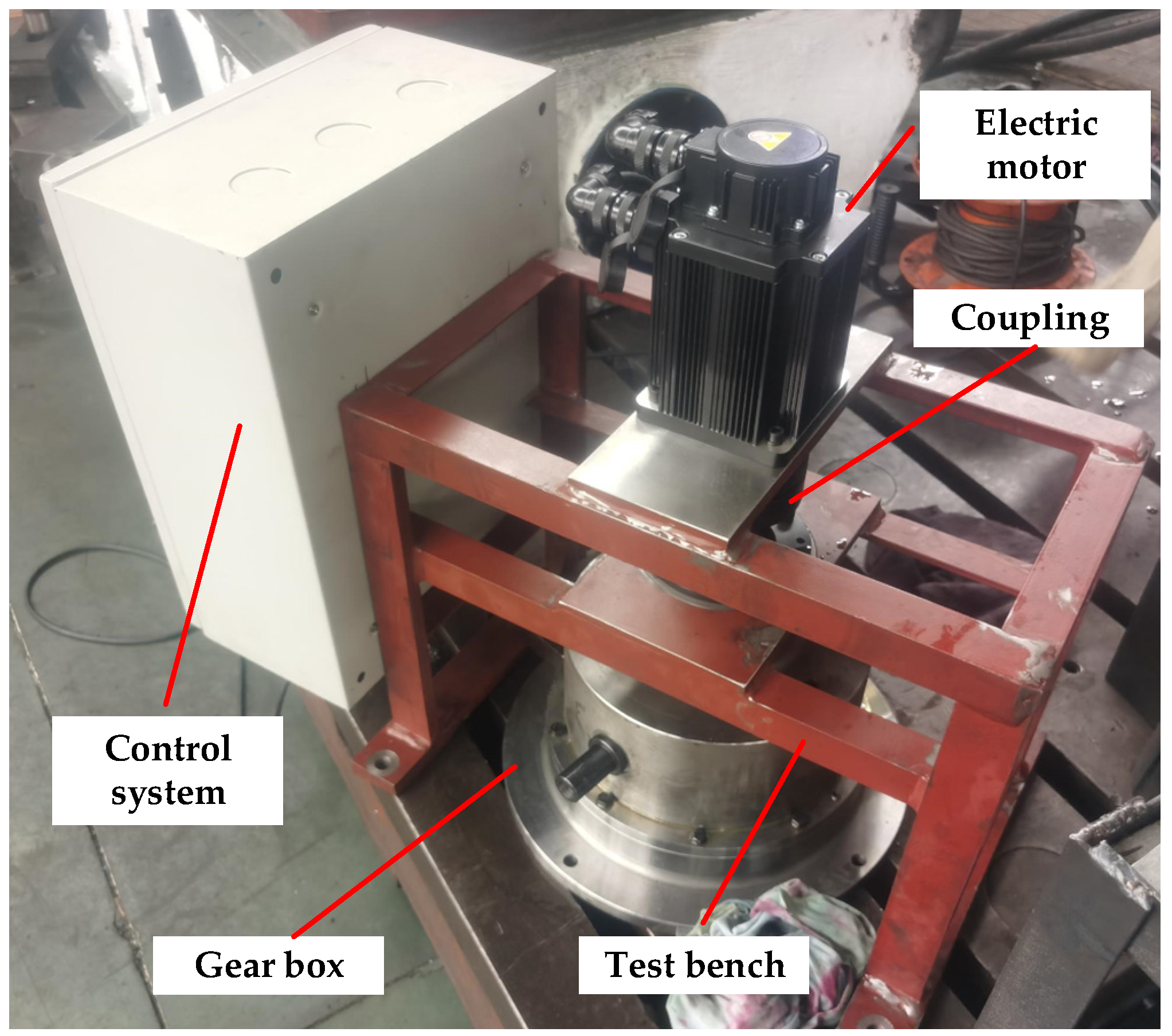
Figure 5.
Internal layout of the test gearbox.
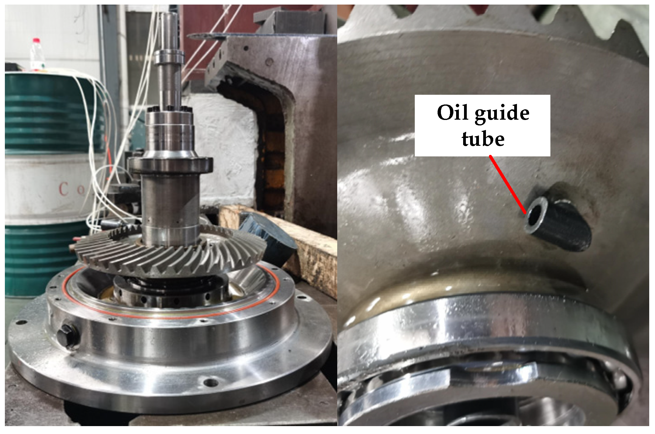
Figure 6.
Comparison of test results and simulation results: (a) H = 40 mm; (b) H = 45 mm; (c) H = 50 mm.
Figure 6.
Comparison of test results and simulation results: (a) H = 40 mm; (b) H = 45 mm; (c) H = 50 mm.

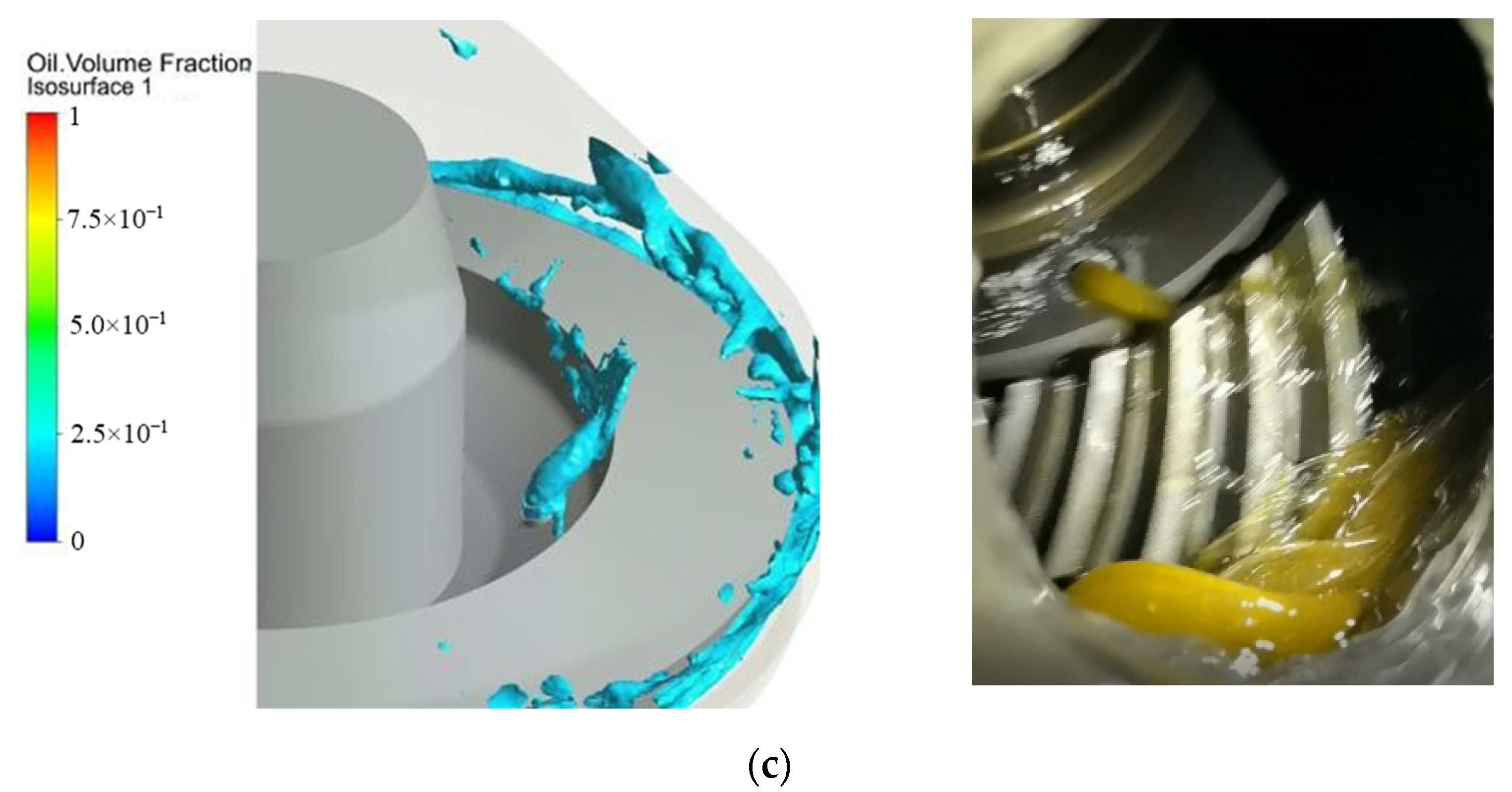
Figure 7.
Instantaneous oil distribution inside the main gearbox: (a) R = 0.5 r; (b) R = 1.0 r; (c) R = 2.0 r; (d) R = 4.0 r.
Figure 7.
Instantaneous oil distribution inside the main gearbox: (a) R = 0.5 r; (b) R = 1.0 r; (c) R = 2.0 r; (d) R = 4.0 r.
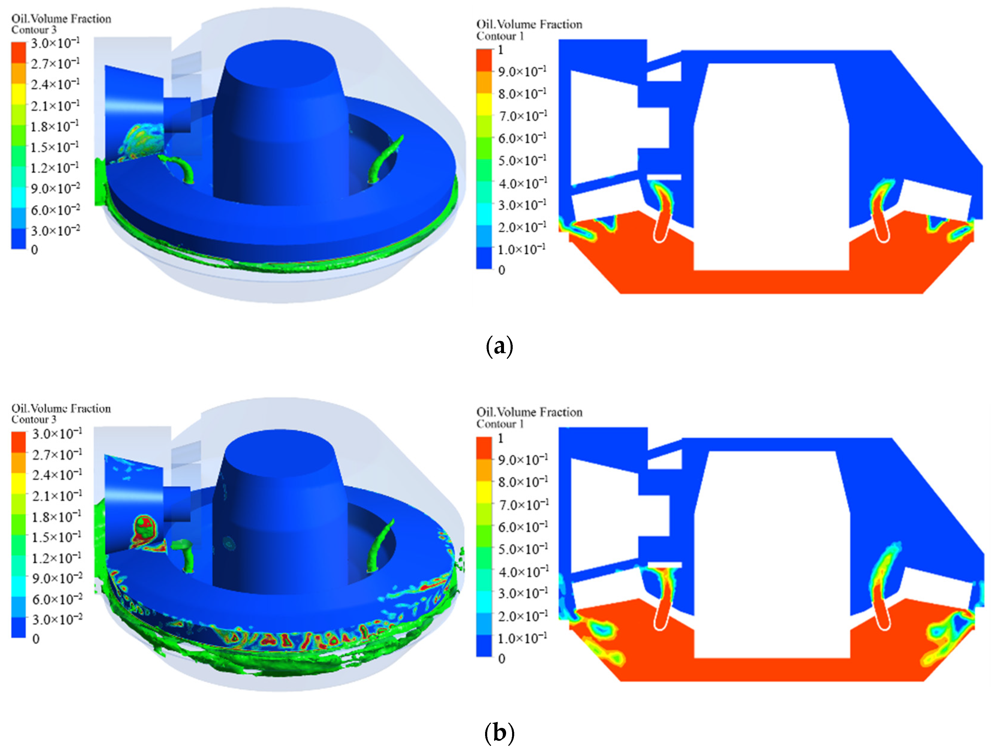
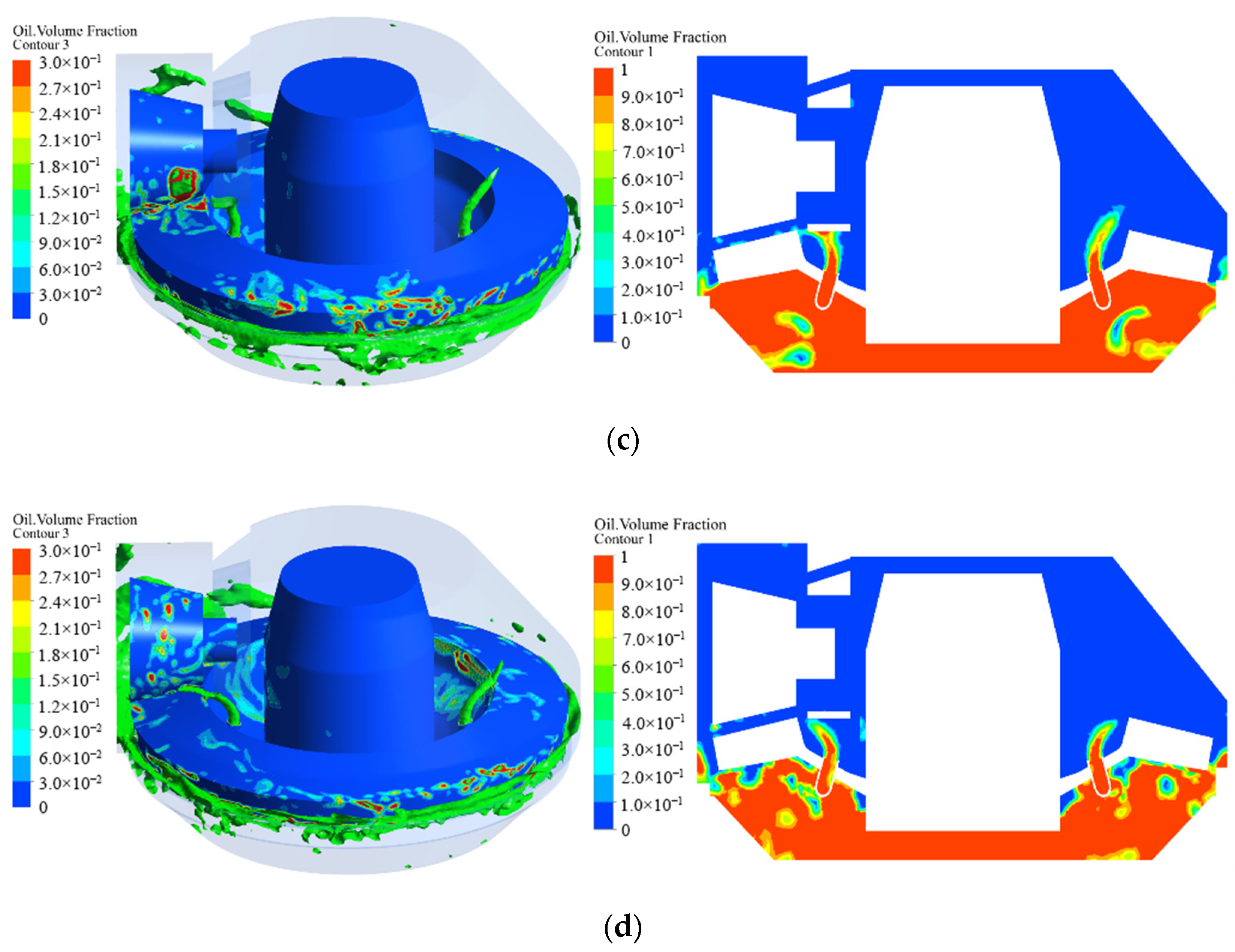
Figure 8.
Geometrical parameters of the oil-guiding tube.
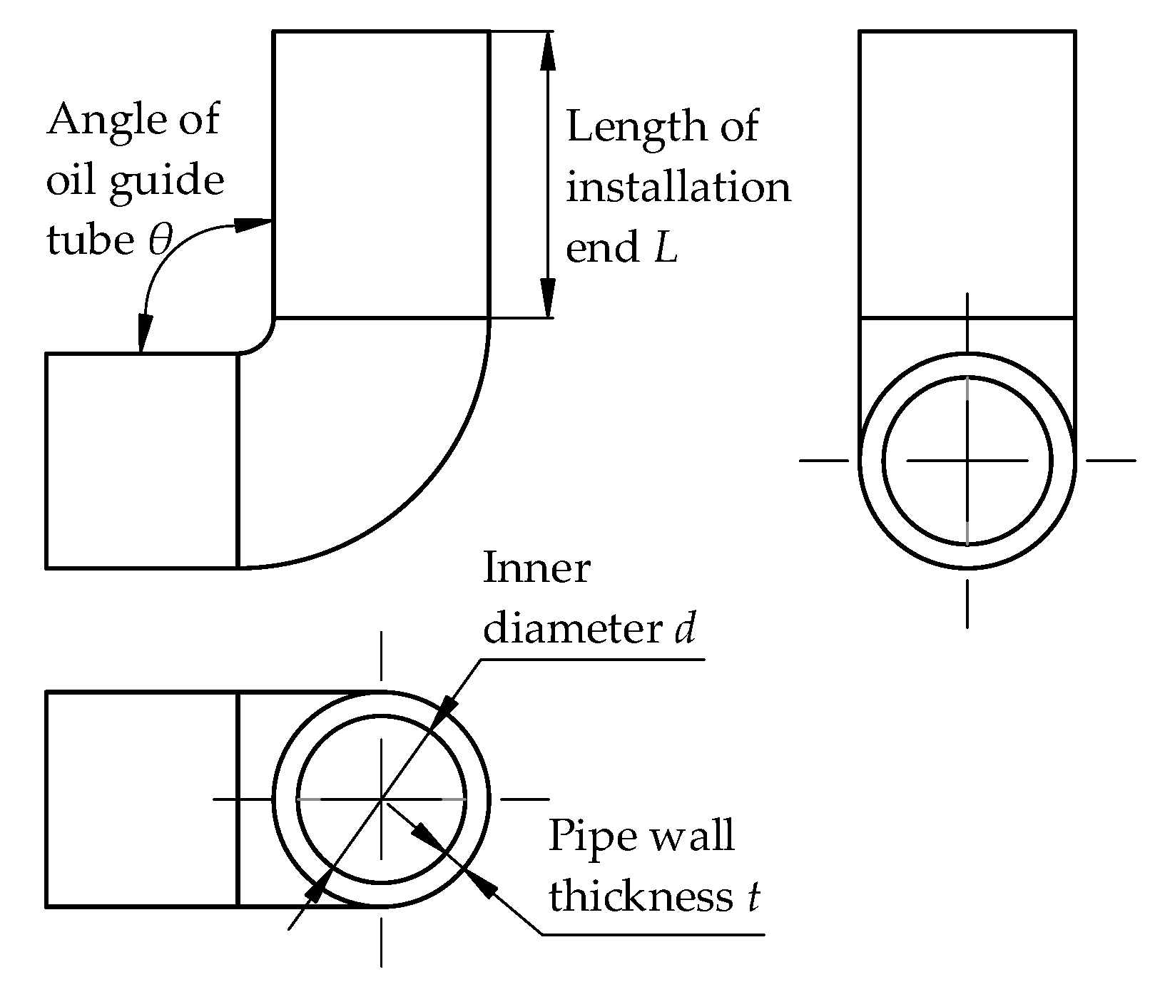
Figure 9.
Oil flow rate of the meshing area at various inner diameters of the oil-guiding tube.
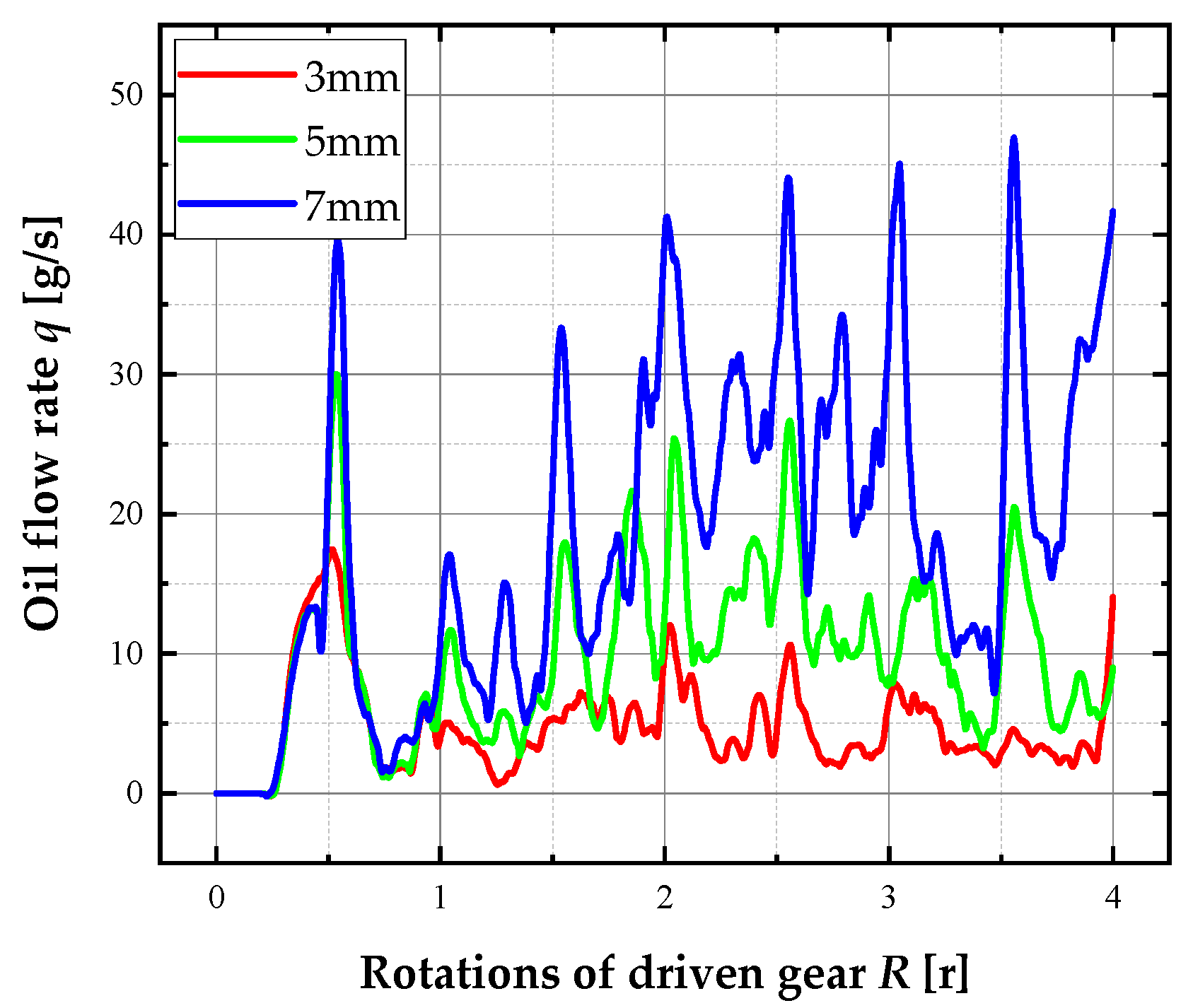
Figure 10.
Oil flow rate of the meshing area at various lengths of installation end of the oil-guiding tube.
Figure 10.
Oil flow rate of the meshing area at various lengths of installation end of the oil-guiding tube.

Figure 11.
Oil flow rate of the meshing area at various angles of oil-guiding tube.
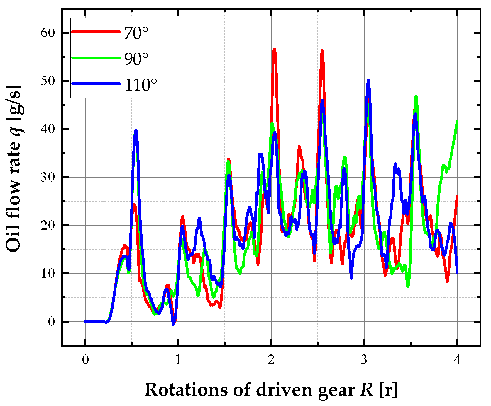
Figure 12.
Oil flow rate of the meshing area at various rotation speeds.
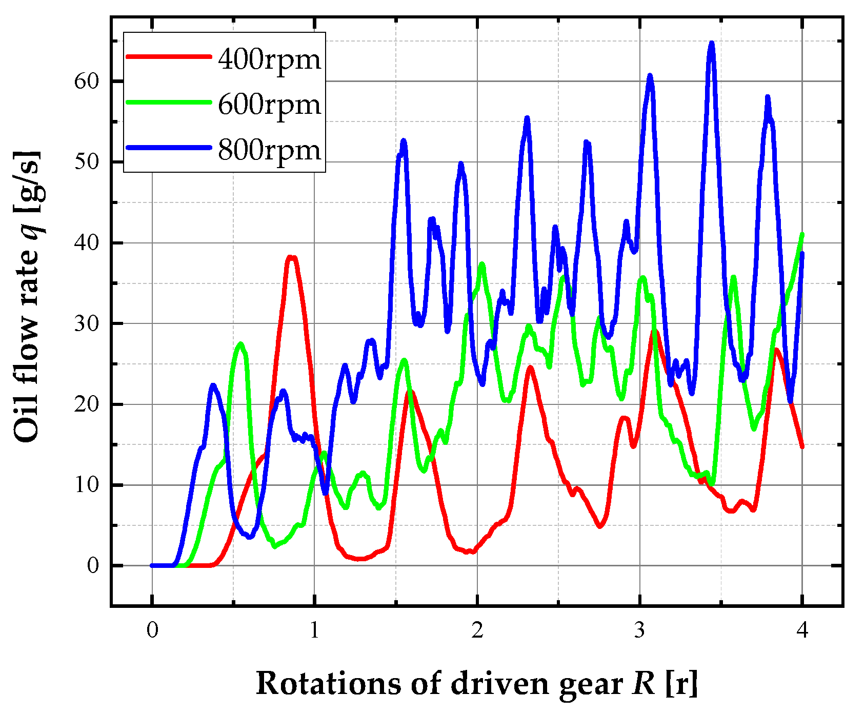
Figure 13.
Oil flow rate of the meshing area at various oil-immersion depths.

Table 1.
Grid independence analysis.
| Number of Grids | Mean Flow Rate of the Monitoring Surface (g/s) | |
|---|---|---|
| Case 1 | 1,172,836 | 23.3 |
| Case 2 | 2,350,738 | 19.3 |
| Case 3 | 3,885,689 | 18.4 |
| Case 4 | 5,976,802 | 18.1 |
Table 2.
Conditions of operation for comparing the flow rate in the gear-meshing area.
| Inner Diameter d (mL) | Length of Installation End L (mL) | Angle of Oil-Guiding Tube θ (°) | Rotation Speed V (r/min) | Oil-Immersion Depth l (mL) | |
|---|---|---|---|---|---|
| Reference case | 7 | 12 | 90 | 600 | 45 |
| Inner diameter 1 | 3 | 12 | 90 | 600 | 45 |
| Inner diameter 2 | 5 | 12 | 90 | 600 | 45 |
| Length of installation end 1 | 7 | 15 | 90 | 600 | 45 |
| Length of installation end 2 | 7 | 18 | 90 | 600 | 45 |
| Angle of oil-guiding tube 1 | 7 | 12 | 70 | 600 | 45 |
| Angle of oil-guiding tube 2 | 7 | 12 | 110 | 600 | 45 |
| Rotation speed 1 | 7 | 12 | 90 | 400 | 45 |
| Rotation speed 2 | 7 | 12 | 90 | 800 | 45 |
| Oil-immersion depth 1 | 7 | 12 | 90 | 600 | 40 |
| Oil-immersion depth 2 | 7 | 12 | 90 | 600 | 50 |
Publisher’s Note: MDPI stays neutral with regard to jurisdictional claims in published maps and institutional affiliations. |
© 2022 by the authors. Licensee MDPI, Basel, Switzerland. This article is an open access article distributed under the terms and conditions of the Creative Commons Attribution (CC BY) license (https://creativecommons.org/licenses/by/4.0/).
Share and Cite
MDPI and ACS Style
Liu, H.; Dai, Y.; Jia, J.; Zhu, X. CFD Investigation into Flow Characteristics of a Special Splash Lubrication in Light Helicopters. Aerospace 2022, 9, 482. https://doi.org/10.3390/aerospace9090482
AMA Style
Liu H, Dai Y, Jia J, Zhu X. CFD Investigation into Flow Characteristics of a Special Splash Lubrication in Light Helicopters. Aerospace. 2022; 9(9):482. https://doi.org/10.3390/aerospace9090482
Chicago/Turabian StyleLiu, He, Yu Dai, Jifu Jia, and Xiang Zhu. 2022. "CFD Investigation into Flow Characteristics of a Special Splash Lubrication in Light Helicopters" Aerospace 9, no. 9: 482. https://doi.org/10.3390/aerospace9090482
Note that from the first issue of 2016, this journal uses article numbers instead of page numbers. See further details here.