
On the Aeroelasticity of the Active Span and Passive Pitching Polymorphing Wing: A Parametric Study


1
Department of Aerospace Engineering, Khalifa University, Abu Dhabi P.O. Box 127788, United Arab Emirates
2
Khalifa University Robotics Institute, Khalifa University, Abu Dhabi P.O. Box 127788, United Arab Emirates
*
Author to whom correspondence should be addressed.
Aerospace 2022, 9(9), 483; https://doi.org/10.3390/aerospace9090483
Submission received: 25 July 2022
/
Revised: 14 August 2022
/
Accepted: 20 August 2022
/
Published: 30 August 2022
(This article belongs to the Special Issue Adaptive/Smart Structures and Multifunctional Materials in Aerospace)
Abstract
:This paper presents an aeroelastic analysis of a polymorphing wing capable of active span extension and passive pitch variation. The wing is split into two segments: an inboard segment responsible for span extension/retraction and an outboard segment capable of pitch variation. The two segments are connected through an overlapping spar and a torsional spring. A finite element aeroelastic model is developed where the wing structure is discretized into Euler–Bernoulli beam elements and the aerodynamic loads are calculated using Theodorsen’s unsteady model. A comprehensive parametric analysis is carried out with and without span extension to analyze the effect of varying critical design parameters, such as elastic axis position of outboard section and torsional spring rigidity, and conditions for aeroelastic phenomena of flutter and divergence are studied. A gust load analysis is carried out to quantify the capability of the outboard wing passive twist mechanism to alleviate loads. Finally, a nonlinear analysis is carried out by replacing the linear torsional spring with a nonlinear cubic spring to study the effects of cubic hardening and softening on the aeroelasticity of the polymorphing wing.
1. Introduction
Morphing refers to a change in shape, structure, or any modification to an original form of a given object. In the realm of aeronautics, it refers to the capability to make changes to any aircraft component, particularly wing configuration, to modify and enhance its flight performance, control authority, and flight envelope [1]. A morphing wing possesses the capability to change its shape to alter its aerodynamic and load carrying capabilities. Since conventional fixed-wing aircraft are optimized for only a certain flight condition, their performance in all other flight phases is sub-optimal. For example, modern aircraft are optimized for a certain design point usually at cruise; however, as the aircraft deviates from that design condition, its performance suffers significantly [2]. An adaptive wing overcomes these limitations by the reconciliation of differing flight requirements to enable optimal flight performance for multiple missions or roles through aerodynamic load adjustment and mitigation, consequently enhancing the aerodynamic performance of the aircraft for a myriad of flight conditions.
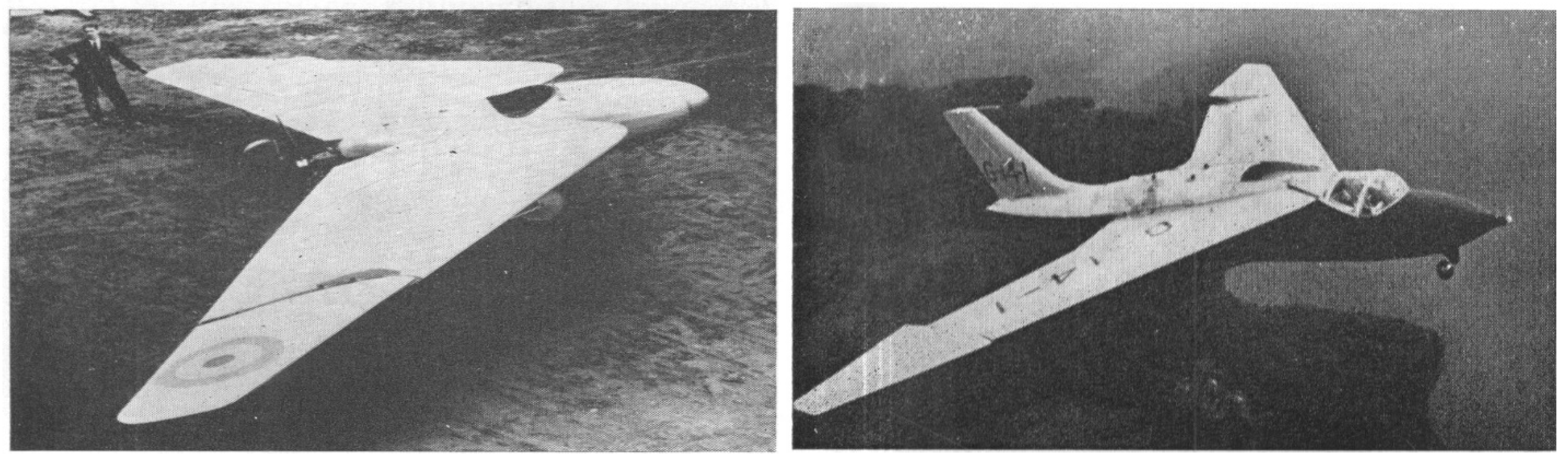
For example, aircraft with large wingspans have higher aerodynamic efficiency but a reduced maneuverability margin when compared to those with low aspect ratios [1]. A span morphing wing can combine the benefits of low and high aspect ratio wing designs, allowing one aircraft to effectively perform various types of missions [3]. Span morphing offers the advantage of enabling efficient flight at high and low speeds. Span variation affects the wing’s aspect ratio, which influences the lift-induced drag coefficient and lift-to-drag ratio. An increase in aspect ratio augments the range and endurance of an aircraft and a decrease in wingspan allows higher speeds and greater maneuverability [3,4]. Another popular wing morphing strategy is twist morphing. It is regarded as the oldest form of wing morphing and can be traced back to the Wright Flyer developed in 1903. The Wright Flyer relied on changing the wing twist via pilot actuation in the cockpit to achieve lateral control. Twist morphing allows altering the wing angle of attack, influencing wing stability, control, maneuverability, and load alleviation, which can then be adjusted for various flight scenarios [5,6]. A series of all-moving wingtip aircraft was developed by Professor JTR Hill in the 1920s and 1930s, known as Hill’s Pterodactyl [7,8]. It featured a controlled variable sweep, as shown in Figure 1, and could perform various flight maneuvers, such as inverted flights, loops, etc. Its performance was judged to be on par with conventional aircraft designs in terms of control stability and maneuverability. However, due to some secondary concerns, the aircraft was discontinued. Another attempt for wingtip twist morphing was realized in the Sherpa SB 4 aircraft, shown in Figure 1. It was an aero-isoclinic wing experimental aircraft, developed as part of a research program by Short Brothers and Harland Ltd. [9,10]. The project aimed to develop a tailless aircraft with a twisting wingtip, which would enable a constant incidence angle for the flight regime. The all-moving wing tip could replace the conventional ailerons by working as elevons whilst also providing control of the control surface loading axis. It could also counteract the tip stall phenomena and rolling moment due to the sideslip of swept-back wings by reducing the incidence angle. However, after several flights and data recordings, the developing company decided against further research on the project.
A monomorphing wing possesses the ability to change its external structure in one degree of freedom, whether it be in terms of span, twist, sweep, or any other form of shape change. Although monomorphing wings are advantageous, their performance is limited due to only a singular added degree of freedom compared to a conventional wing. An emerging trend in the field of morphing aircraft involves developing wings capable of multiple degrees of morphing. Research is ongoing regarding implementing two or more of these morphing mechanisms simultaneously in a single aircraft system to achieve superior characteristics; such aircraft wings are referred to as polymorphing wings [4,6,11,12]. A polymorphing wing is a concept comprising an aircraft wing having the capability of undergoing two or more morphing degrees of freedom (DOF). Polymorphing wings promote superior aircraft performance by deriving benefits of multiple morphing mechanisms and optimizing wing configuration to achieve multi-mission capabilities. However, such systems are accompanied by an increase in complexity, weight, cost, and reduction in reliability [13]. Incorporating multiple morphing schemes into one aircraft system leads to a complex interaction between the mass, stiffness, and damping matrices. While one morphing scheme can enhance a certain parameter of performance, it could have a debilitating effect on other structural, aerodynamic, or aeroelastic properties. For example, span extension allows superior range, endurance, and lower induced drag, increasing aerodynamic performance. However, it also leads to lower flutter and divergence velocity and significantly higher root loads. Similarly, twist morphing can be used to reduce root loads by placing the elastic axis of the rotating section ahead of the wing aerodynamic center, but it comes with a penalty of reduced aeroelastic stability and lower flutter and divergence velocity. Therefore, it is imperative to study the aeroelasticity of any polymorphing wing system in the initial design stage to quantify any advantages offered by it and assess any imposed risks or limitations.
One such concept of an active span and passive pitch extension (ASAPP) wing is presented by Ajaj et al. [6], which compromises a polymorphing wing capable of span extension in the inboard wing section, and a passive pitching outboard section. The elastic axis (ea) of the outboard wing section is located ahead of the aerodynamic center, which enables load alleviation properties.
This study focuses on polymorphing wings equipped with span and twist morphing as they are dubbed as two of the most promising morphing degrees of freedom due to their huge potential in terms of flight performance, flight control, aeroelastic control, and load alleviation. For this purpose, the ASAPP wing is used as the subject of this study as it serves as an ideal model of a modern polymorphing wing design. The scope of this paper pertains to determining aeroelastic phenomena encompassing the morphing of the ASAPP wing, particularly span and twist morphing, and conducting parametric and sensitivity studies by varying key aerodynamic and structural parameters and observing their aeroelastic response. A quasi-static gust load analysis is also carried out to observe the properties of the outboard passive pitch twist mechanism in alleviating root loads on the wing structure. Lastly, structural cubic nonlinearities are introduced into the system by integrating hardening and softening effects in the outboard section torsional pitch spring, and their effect on the system is examined.
Active Span Extension and Passive Pitch (ASAPP) Wing
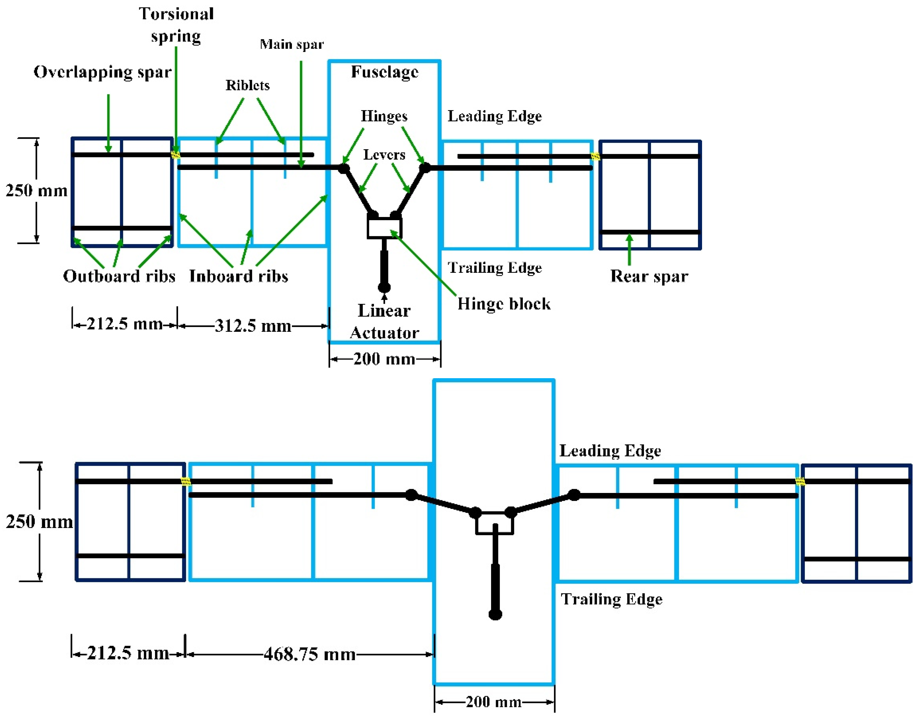
The ASAPP wing is a novel concept introduced by Ajaj et al. [6,14] to exploit the benefits of polymorphing wing technology by integrating two degrees of a freedom morphing mechanism in a single wing design (Figure 2). Each side of the wing is divided into two segments: inboard and outboard. The inboard segment is responsible for span extension/retraction actuated using a linear actuator placed inside the fuselage, while the outboard segment is connected to the inboard section using an overlapping spar and a torsional spring, which allows the outer section of the wing to rotate (as a rigid body) as per the spring stiffness and the acting aerodynamic loads, resulting in passive pitch variation. The structure of the wing consists of the main spar, which runs through the inboard section of the wing, and an overlapping spar, which is located at 20% of the chord and passes through two of the three ribs on the inboard section for load transfer, as shown in Figure 2 and Figure 3. The overlapping spar is located ahead of the wing aerodynamic center, and, hence, increasing aerodynamic loads tend to pitch down the outboard segment, leading to a reduced bending moment and increased aerodynamic efficiency in the inboard section. Ajaj et al. [6] analyzed the aerodynamic characteristics and structural aspects associated with the ASAPP wing. Polymorphing wings (including the ASAPP wing) are associated with large changes in their aerodynamic, elastic, and inertial properties as they morph [15,16,17,18]. Therefore, it is very essential to study the aeroelastic behavior of the ASAPP wing (which forms the basis of this study) to be able to quantify its full benefits and potential in a range of flight conditions and loading scenarios.
2. Modeling and Validation
2.1. Structural Dynamics Model
The developed structural model is valid for tapered and swept wings; however, for simplicity, the wing is modeled as a uniform, rectangular beam and discretized into Euler–Bernoulli beam elements to be solved using a finite element solver developed on MatlabTM (Las Vegas, NV, USA). A clean configuration wing is chosen for the analysis; i.e., no flaps, slats, or other high lift devices are assumed on the lifting surface. Lagrange’s method is used to obtain the equations of motion. For a beam undergoing coupled bending and torsional vibration, the kinetic energy (T) can be defined as [19]:
where m’ is mass per unit length, w is bending deflection, θ is the angle of twist, t is time, e is the distance between the elastic axis and center of gravity (cg), rα is the radius of gyration, l is the half span length of the wing, and x is the position along the span. The potential energy (U) is given as:
where EI is the bending rigidity, GJ is torsional rigidity, J is the torsional constant, Cw is the warping constant, and E is Young’s modulus. A schematic of the beam element undergoing bending and torsion is shown in Figure 4.
For transverse vibration of the Euler–Bernoulli beam, four nodal variables are required: w1, w2 and ϕ1, ϕ2, which represent the bending deflection and slope on the 2 nodes of the beam element, respectively. Hence, a cubic polynomial function is assumed for w(x) to satisfy four boundary conditions [21]:
where , , , and are the shape functions.
Similarly, a linear shape function is used to approximate the torsional deflection of the beam element and is given as:
where and are the linear shape functions.
Since a linear shape function is used to account for torsion, the effects of warping cannot be captured in the developed model, and, hence, wing-warping effects are not included in the scope of this study. Lagrange’s equation is used to derive the equation of motion, and the elemental stiffness (K) and mass (M) matrices are calculated. Beam bending and torsional elemental matrices can be combined using an independent notation of nodal displacements to form a 6 × 6 matrix representing both bending and twisting. Since the mass axis does not coincide with the elastic axis, coupling terms are present in the elemental mass matrix due to inertia coupling. Each elemental matrix is multiplied by a transformation matrix to transform the local coordinate system into a global coordinate system. The transformation matrix is constructed using Euler angles to account for wing sweep, dihedral, and twist. Each mass and stiffness element is transformed to global coordinates using the transformation matrix before being added to the global matrices.
2.2. Aerodynamic Model
The developed aerodynamic solver is based on Theodorsen’s unsteady lift model using strip theory. Theoodorsen’s model approximates lift and moment around a symmetric airfoil using 2-D approximations; therefore, it is unable to account for the 3-D flow effects, such as induced flow, downwash, and wing tip vortices. These 3-D effects could have a significant effect on the performance and capabilities of the outboard passive twist section; however, since ASAPP wing is undergoing span extension, it is expected that 3-D flow effects and their influence on passive pitching mechanism are of minor concern. Moreover, the objective of this study is to analyze the sensitivity of various parametric changes instead of absolute magnitude of quantities; therefore, the underlying assumptions concerning Theodorsen’s model seem apt for analysis at this point of study.
As per aerodynamic strip theory, the wing is subdivided into several spanwise elements, with each strip assumed to have an infinite span. This allows 2-D aerodynamic approximations for lift and moment to be applied over each element and integrated over the wingspan. Theodorsen’s model contains circulatory and non-circulatory terms to include the effect of added mass and wake vorticity, respectively. It builds upon the quasi-steady thin airfoil theory by multiplying the lift coefficient by Theodorsen’s transfer function, C(k), to incorporate the effects of magnitude attenuation and phase lag. An ‘apparent inertia’ term is further added to the lift coefficient to account for the reaction force of the fluid mass flow in case of rapid maneuvering [22,23,24].
The unsteady lift and moment per unit span around the elastic axis for a symmetric 2-D airfoil is given as:
where is the fluid density, b is half-chord, V is velocity, is normalized pitch axis location, k is reduced frequency, and C(k) is Theodorsen’s transfer function, which is given as [24]:
By substituting the oscillatory harmonic heaving and pitching expression and the complex form of Theodorsen’s function, the lift and moment equation can be derived in their oscillatory derivative form, which is expressed as:
where , , , , , and are nondimensional oscillatory aerodynamic derivatives normalized for heave and pitch by displacement and velocity. The complete expressions for the aerodynamic derivatives can be found in the Appendix A in Table A1. The aerodynamic loads on a strip element can be obtained by application of the principle of virtual work and integrated for the length of the airfoil, and they can be expressed as [20]:
represents the shape functions in bending and torsion and is given as:
The above expressions can be used to derive the aerodynamic damping and stiffness matrices as given below:
where and are given as:
2.3. Aeroelastic Model
The wing surface is discretized into a number of elements and a finite elements solver is used to compute the structural stiffness and mass matrices for each element. Aerodynamic stiffness and mass matrices are dependent on the reduced frequency (k), and, hence, a frequency matching method (pk) method [25] is used to determine these quantities. Using Euler’s transformation matrix, each element is transformed from a local coordinate system to a global coordinate system. Subsequently, all the elements are assembled into global stiffness and mass matrices and expressed in the following form:
where A, D, and E represent structural inertia, damping, and stiffness matrices, respectively, and B and C denote aerodynamic damping and stiffness, respectively. Equation (16) can be used to study the system’s frequency and damping response against variation in velocity and, hence, can be used to determine the aeroelastic phenomena of flutter and divergence.
2.4. Gust Load Modelling
A discrete 1-cosine gust model is used, and its profile is defined in accordance with FAR Part 25, Section 25.341 [20]. Upward and downward gust loads are considered, and the variations in root bending moment and root shear force are calculated. The temporal variation in gust velocity is defined as:
where H is the gust gradient, which is the distance required for the gust to reach its peak value, in the parallel direction to the flight path. Uds is the design gust velocity and is defined as:
where Uref is the reference gust velocity, which varies linearly from 17.07 m/s at sea level to 13.4 m/s EAS at 15,000 feet. Fg is the flight profile alleviation factor and is set as 1 for this analysis.
2.5. Model Validation
The Goland wing is used for validation of the developed aeroelastic model. Flutter and divergence calculations for the Goland wing are pervasive in literature; therefore, it serves as an ideal test subject. Moreover, for this paper, the ASAPP wing configuration is also integrated into Goland wing specifications. The specifications of the Goland wing are given below in Table 1.
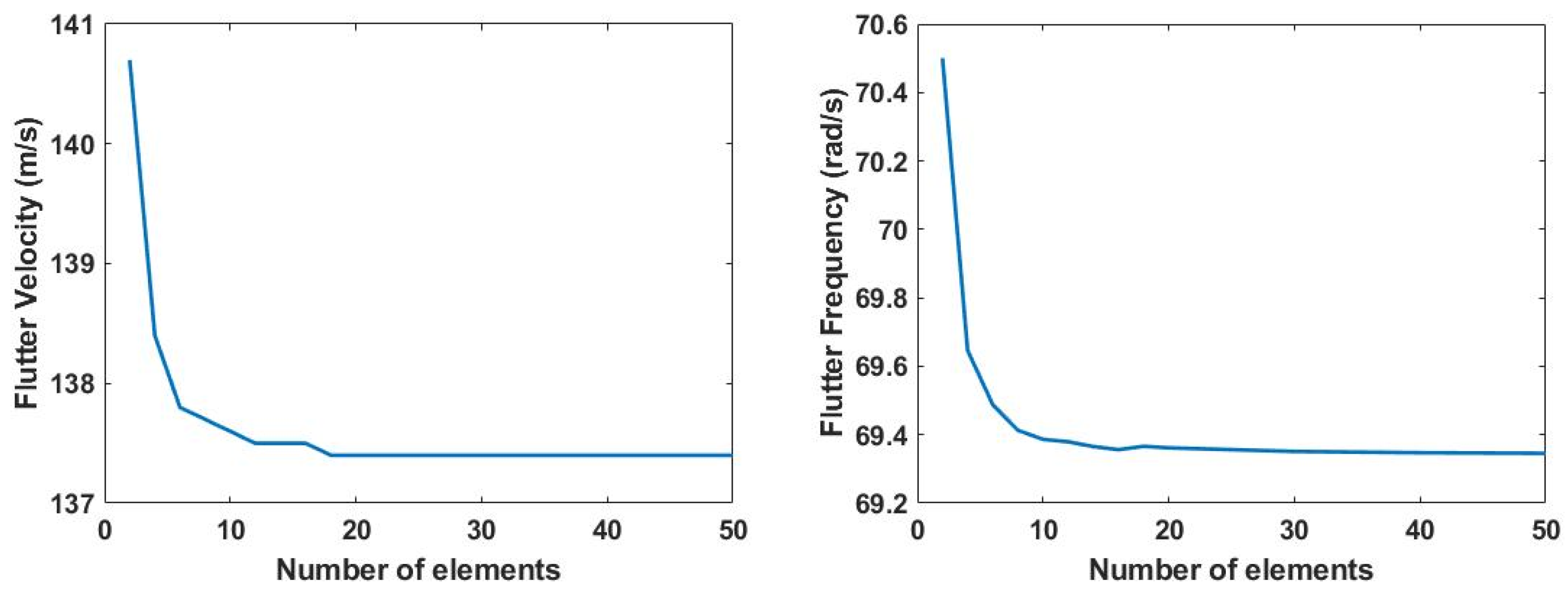
For validation, the Goland wing is discretized and aeroelastic boundaries are determined. The inboard and outboard wing sections are divided into an equal number of elements, and the adjoining torsional spring is represented by a single element of fixed length (0.1 m). The spring torsional rigidity is varied by substitution in the potential energy equation given in Equation (2). A convergence study is carried out to ensure the accuracy of the obtained results and determine the minimum number of required elements. The results for the convergence study are presented in Figure 5. The results exhibit that a converged solution is obtained for 19 total elements and above for the developed model.
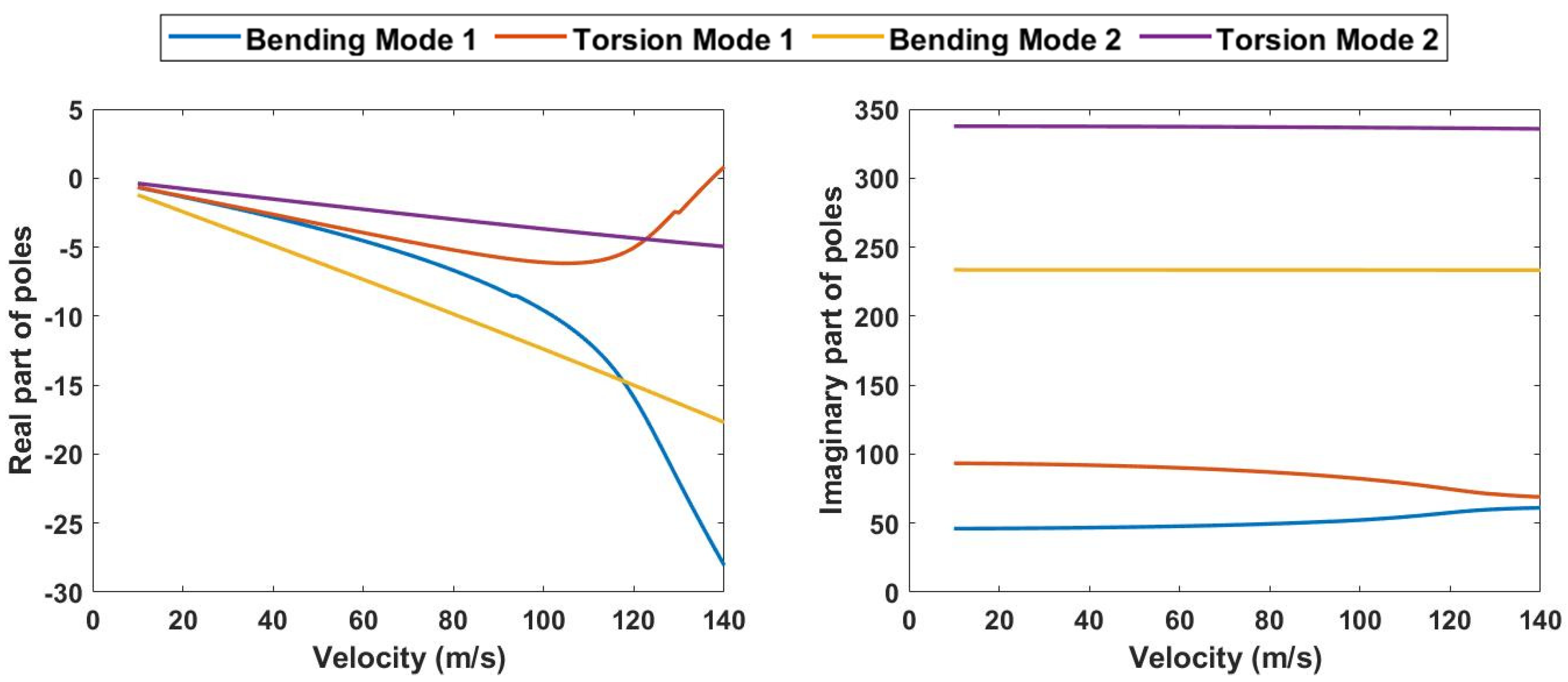
To minimize the numerical error, the wing is divided into 19 elements: 9 each for inboard and outboard section and 1 for adjoining torsional spring for the analysis. The frequency and damping variation for the model is given in Figure 6. The model exhibits excellent accuracy to predict aeroelastic flutter and divergence velocity in comparison to available literature data, as is evident from Table 2.
3. Parametric Study
The parametric analysis is performed by integrating the polymorphing capability of the ASAPP wing into a Goland wing configuration. Therefore, the baseline wing specifications correspond to a 33% chordwise position of the elastic axis, a 43% chordwise position of the center of gravity, and the adjoining torsional spring rigidity identical to the torsional rigidity of the Goland wing. The parametric study is performed for a wing without span extension, 25% span extension, and 50% span extension. The details of the three wingspan configurations are shown in Table 3 below.
3.1. Variation in Elastic Axis and Torsional Rigidity at 0% Span Extension
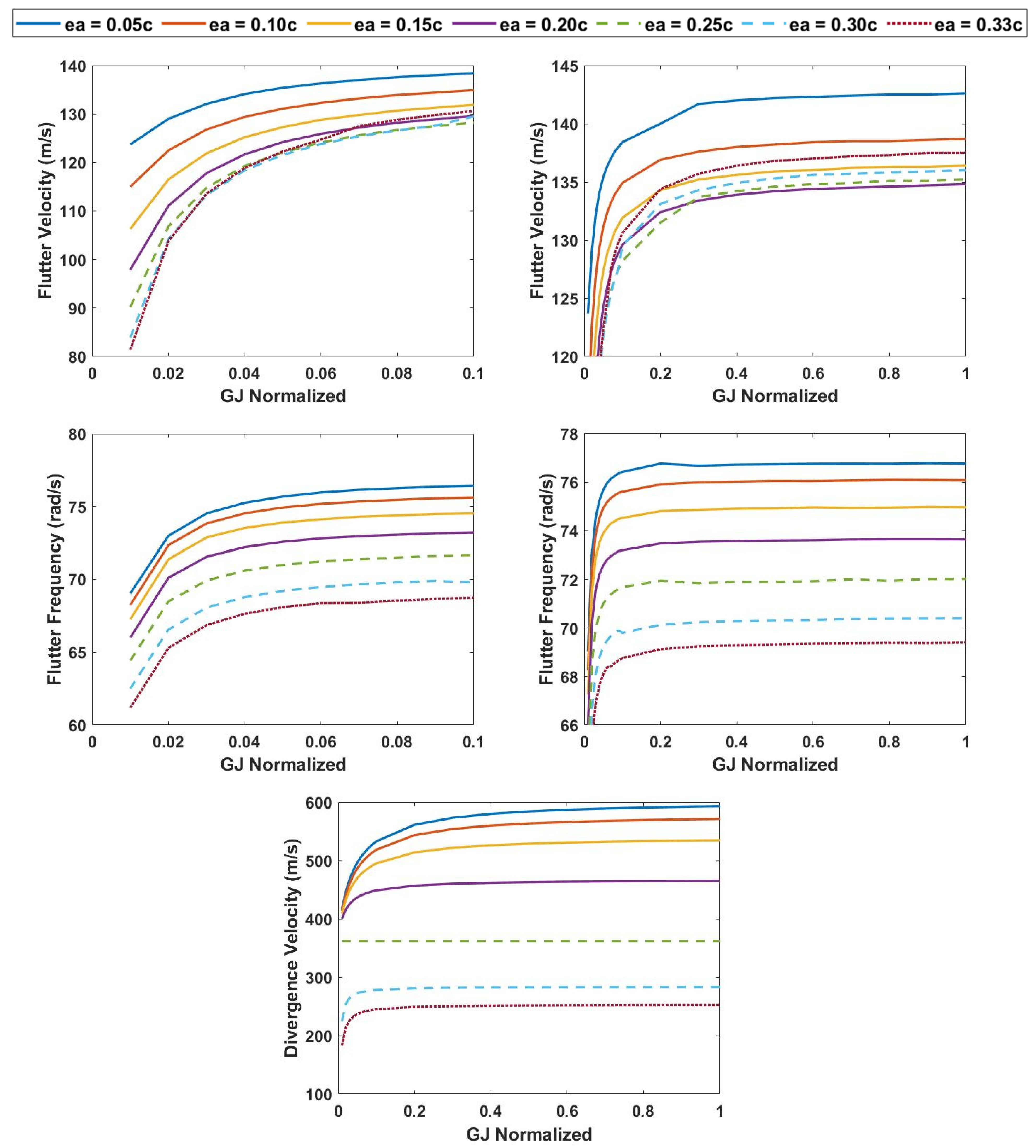
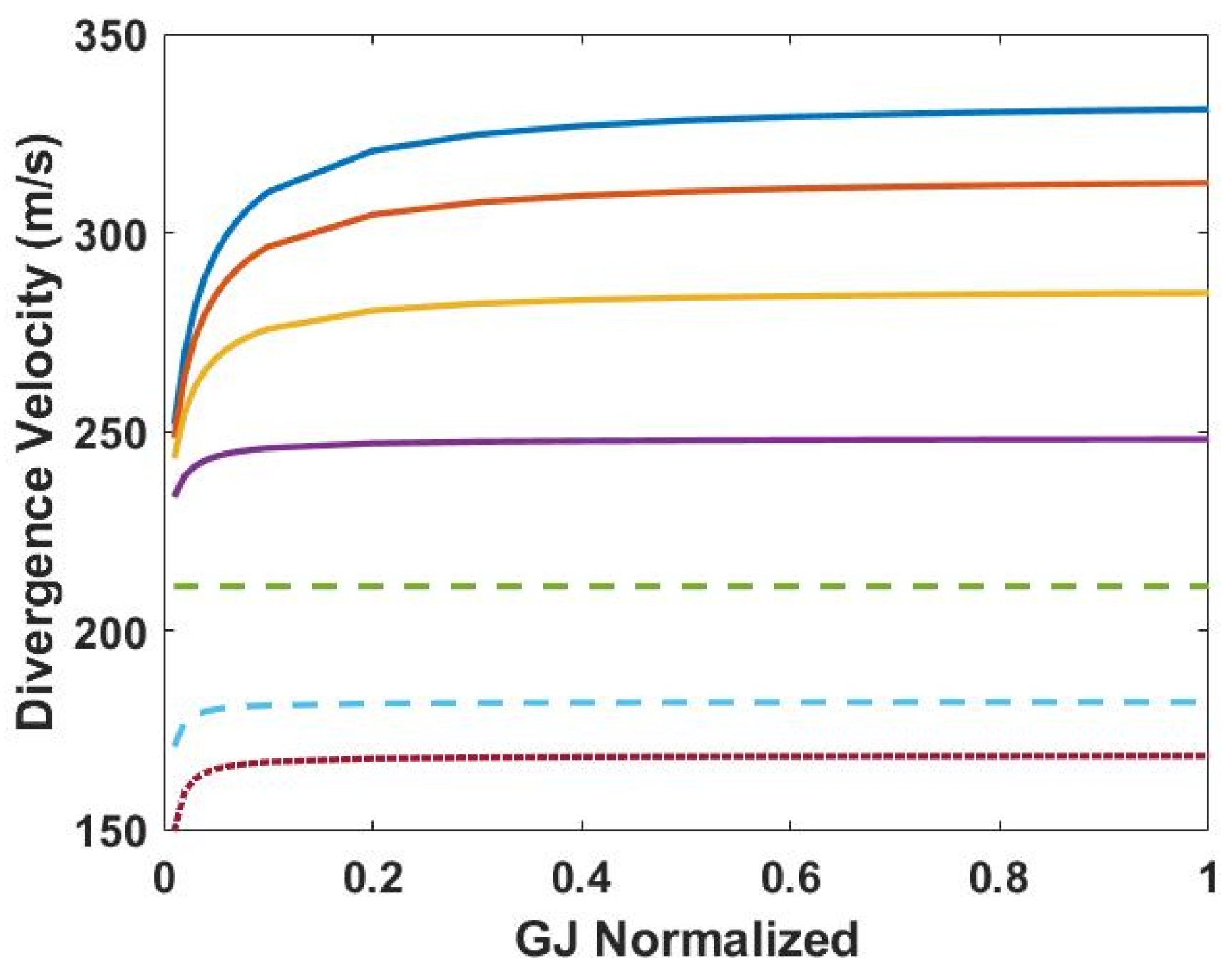
The variation in flutter velocity for change in elastic axis position of the outboard wing segment and variable torsional rigidity of the connecting spring is evaluated. For each elastic axis position, the spring torsional rigidity is varied from 1% to 100% of the baseline wing value (listed in Table 1). The procedure is repeated for each elastic axis position, starting from 5% of the chord to 30%, from the leading edge, with an increment of 5% for each calculation. The case for the baseline Goland wing is represented by a 33% elastic axis position at 100% torsional rigidity case to determine the relative change in aeroelastic properties. The results are plotted against torsional rigidity normalized from the baseline configuration. It is evident from Figure 7 that flutter velocity decreases as the position of the elastic axis is moved farther from the leading edge for the 1% torsional rigidity case. An increase in spring torsional rigidity is followed by an increase in flutter velocity. However, the flutter velocity for ea positions following 20% chordwise position shows a more rapid increase in flutter velocity with an increase in torsional rigidity, the greatest increase being for the 33% ea case, followed by 30% and 25% ea cases, respectively. At 1% and 100% torsional rigidity cases, the minimum ea position shows a 52% and 3.7% increase in flutter velocity compared to the baseline configuration, respectively. Moreover, the ea positions following the 10% chordwise mark register a lower flutter velocity than the baseline test case. The highest flutter frequency is observed for the minimum elastic axis position, which decreases as the elastic axis is moved farther from the leading edge. A similar trend can be seen for divergence velocity in Figure 7, with higher divergence velocities for the elastic axis closer to the leading edge and higher torsional rigidity of the spring. However, divergence exhibits a lower sensitivity to torsional spring rigidity in comparison to flutter. An approximate increase of 135% is observed in divergence velocity, at 100% torsional rigidity and 0.05c elastic axis location, from the baseline configuration.
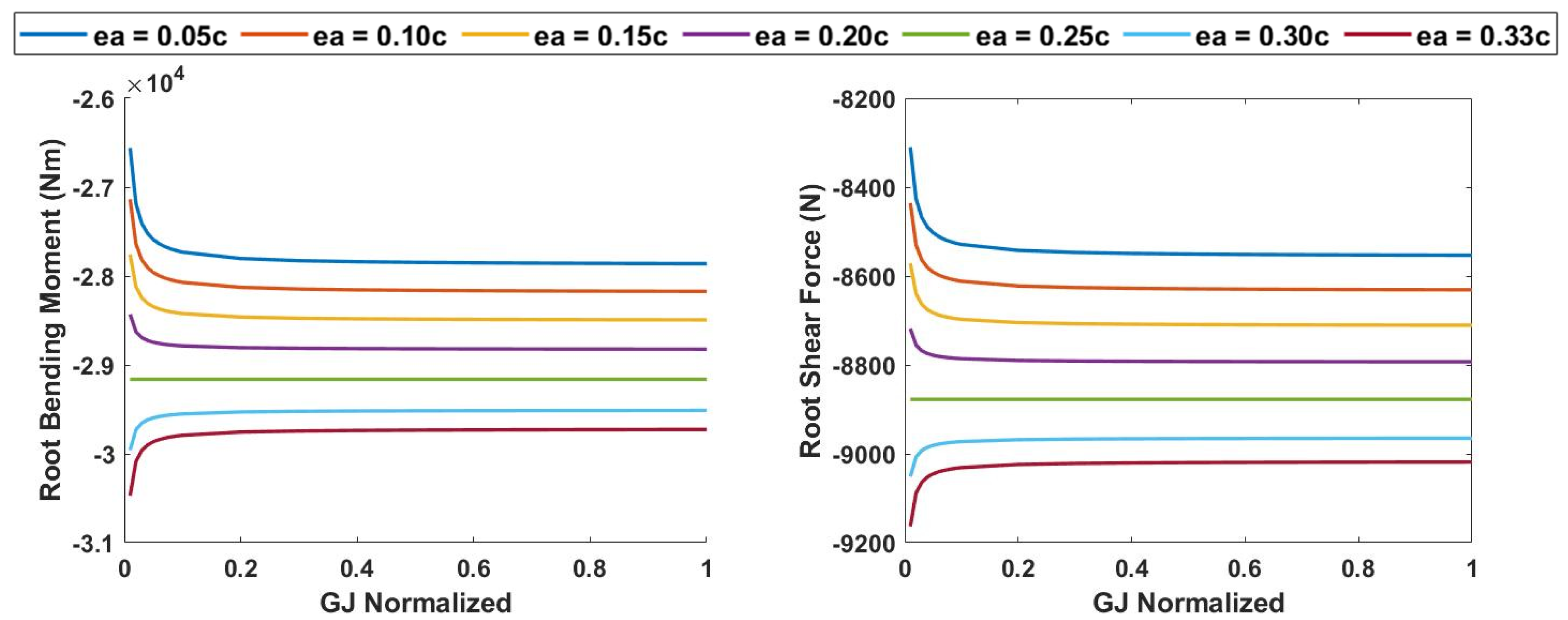
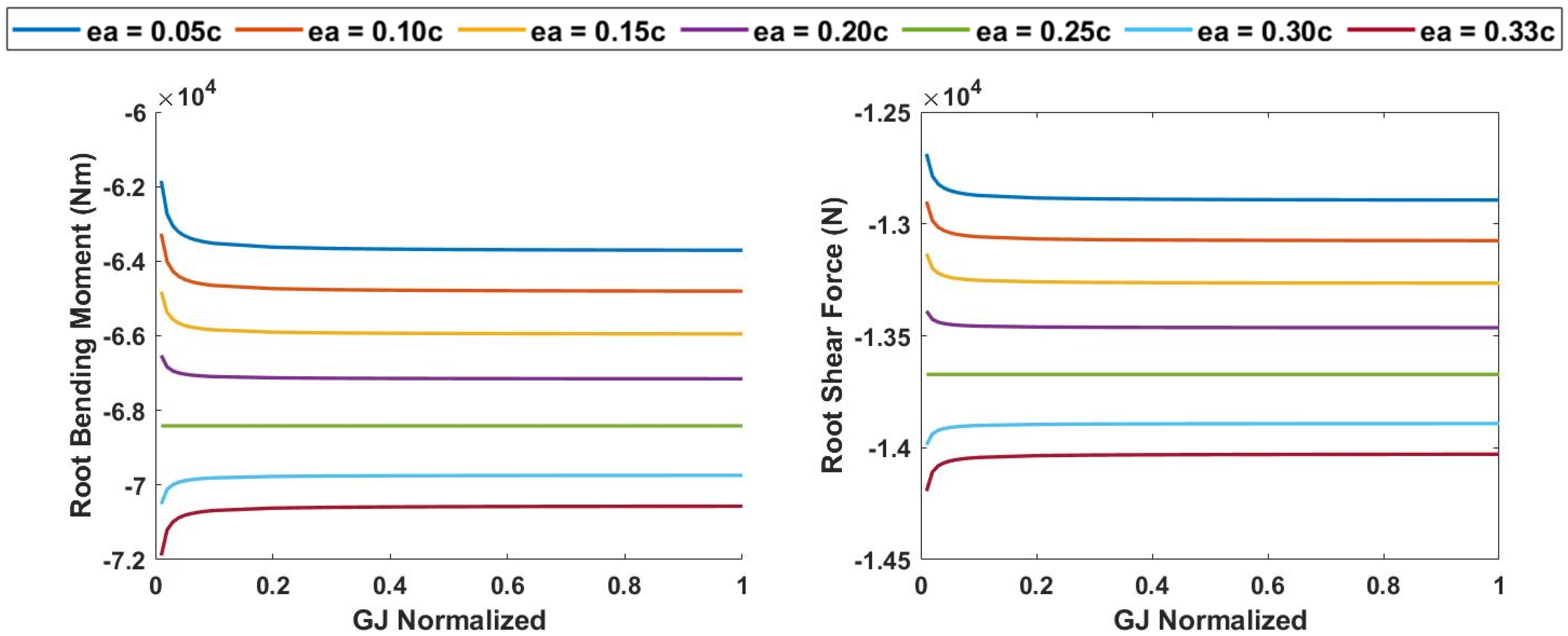
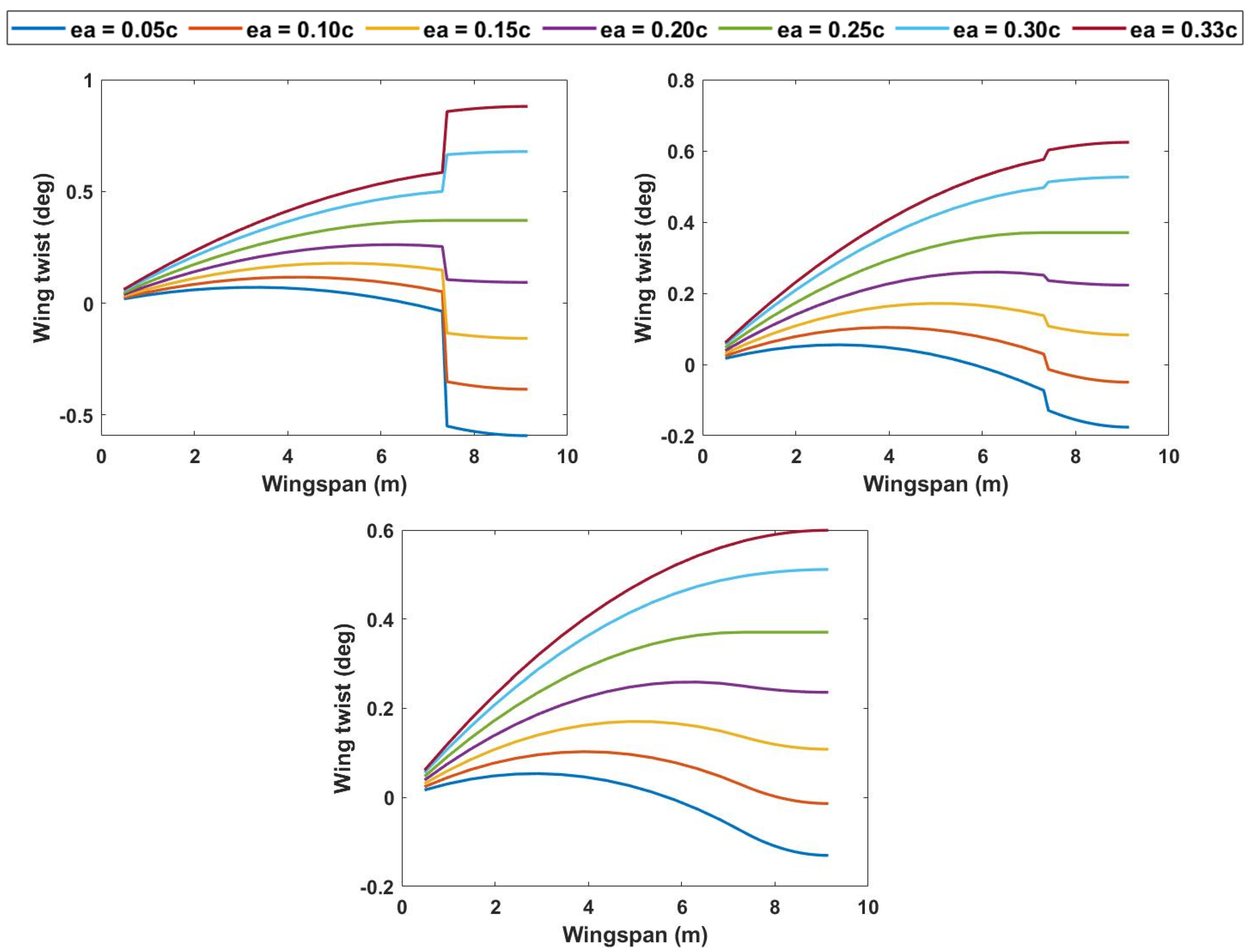
To analyze the effectiveness of the passive pitching mechanism, the polymorphing wing is set at a velocity of 50 m/s and a 5-degree angle of attack. The root bending moment is calculated for various elastic axes and compared to a baseline wing performance (without the pitching mechanism). It can be seen in Figure 8 that the passive pitching mechanism significantly reduces root bending moment loads. This is attributed to the outboard passive pitching mechanism moving opposite to the inboard wing and acting against its produced loads to reduce the overall bending moment encountered at the wing root. The baseline wing configuration is at the 0.33c point, and it should be noted that any movement of the elastic axis towards the leading edge, from that point, results in a lower root bending moment from the baseline wing. The root bending moment, however, shows only slight sensitivity to torsional rigidity for very low values but is not much affected for larger values. The torsional spring mechanism reduces the root bending moment load by approximately 12.8% for the minimum ea position and torsional rigidity from the baseline configuration, and 6.3% from the baseline configuration for the minimum ea position at 100% torsional rigidity. Similarly, the root shear force exhibits a 9.3% decrease from the baseline configuration at the point closest to the leading edge for minimum torsional rigidity and a 5.2% decrease at 100% torsional rigidity. The variation in twist across the wingspan is shown in Figure 9. The greatest twist is shown for the lowest value of torsional rigidity, leading to greater defection of the passive wing twist mechanism.
3.2. Variation in Elastic Axis and Torsional Rigidity at 25% Span Extension
The wingspan is quasi-statically increased to 125% of the baseline configuration and a similar analysis as before is carried out to study the effect of span morphing on aeroelastic boundaries and wing root bending moment. The span of the outboard segment is kept constant, and the span extension is carried out in the inboard segment of the wing. The results for the change in flutter and divergence velocity with a variation in elastic axis and spring torsional rigidity are plotted in Figure 10. A significant reduction in flutter and divergence velocity with an increase in wingspan is evident. An increase in wingspan affects the structural stiffness of the lifting surface, which negatively influences the system stiffness and damping, and, hence, results in lower velocity flutter and divergence. However, it should be noted that the position of the elastic axis closer to the leading edge affects the flutter and divergence positively at minimum torsional rigidity, resulting in a 5.8% higher flutter velocity than the baseline configuration value at minimum ea position. The elastic axis positions farther from the leading edge exhibit a steeper increase in flutter velocity, with an increase in torsional rigidity, than the closer ones. Consequently, at 100% torsional rigidity, the greatest flutter velocity is observed for the farthest ea case, which decreases as ea position comes closer to the leading edge. Conversely, divergence velocity shows a positive increase for minimum ea position and decreases as the elastic axis position is moved aft of the leading edge. It is shown to be 69.8% greater than the baseline wing configuration.
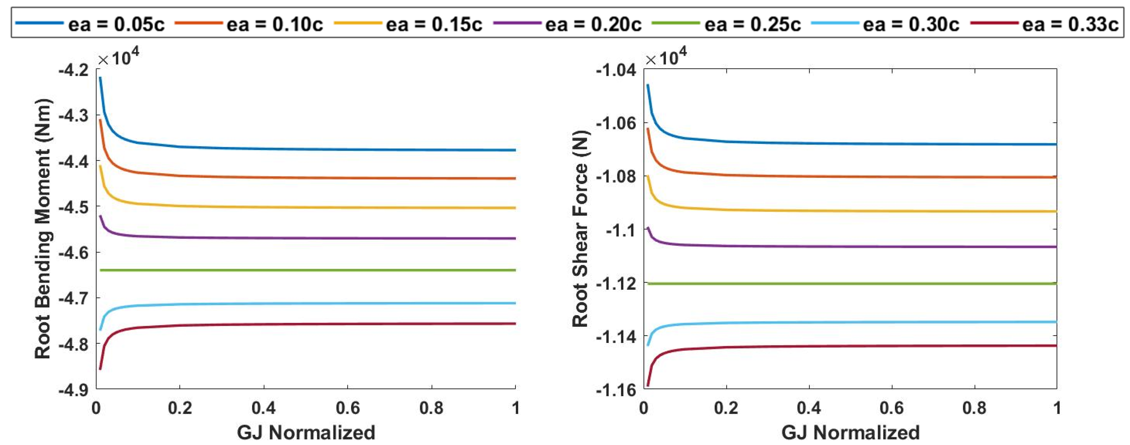
The root bending moment significantly increases due to the longer wingspan, as shown in Figure 11; however, a difference of approximately 47.2% is evident for the lowest elastic axis position and the baseline position compared to a 60% increase in root bending moment if the span extension were to be carried out on a non-pitch-twisting wing. Furthermore, the ASAPP wing exhibits an increase in root shear force of 18.5% at the minimum elastic axis position as compared to the baseline wing configuration and 26.8% lower than the shear force at 25% span extension without the pitch twist mechanism. The wing twist shown in Figure 12 indicates a 2.7% decrease in the angle of twist for the lowest value of GJ at minimum ea and a 6% decrease in twist angle for 100% GJ as compared to similar torsional rigidity and elastic axis position without span increase.
3.3. Variation in Elastic Axis and Torsional Rigidity at 50% Span Extension
The change in flutter and divergence velocity with a variation in elastic axis and spring torsional rigidity for 150% wingspan of the baseline configuration is plotted in Figure 13. The flutter velocity for this case exhibits an increase in value with the farther movement of the elastic axis position, the greatest value being for the baseline case of 33% chordwise ea location. There is a 30.8% decrease in flutter velocity at the minimum ea position and a 24% decrease at the 33% chordwise ea position in comparison to the unmorphed baseline configuration. The decrease in the aeroelastic influence of the outboard pitch twist mechanism can be attributed to the outboard section span length being kept constant, for an overall 50% increase in the inboard section of the wingspan. Hence, the amount of force generated due to the mechanism plays a smaller role in damping the aeroelastic phenomena of flutter and divergence. This suggests that a trade-off is necessary between the force produced by the twisting mechanism, its moment arm length, and the change in outboard section span to obtain maximum benefits from the configuration. The divergence velocity is 31% greater than that of the baseline wing configuration.
An increase of 113.6% in root bending moment and a 43% increase in root shear force at minimum elastic axis position for a 50% increase in wingspan is shown in Figure 14. Although the change in loads is substantial, the root bending moment and root shear force are still 10.6% and 8.1% lower, respectively, than the configuration without a pitch twist mechanism. The wing twist shown in Figure 15 shows a 9.4 % decrease in the angle of twist for the lowest value of GJ at minimum ea and a 28.3% decrease in twist angle for 100% GJ as compared to similar torsional rigidity and elastic axis position without span increase.
3.4. Aeroelastic Effect of Varying Outboard Wing Center of Gravity to 33% Chordwise Position
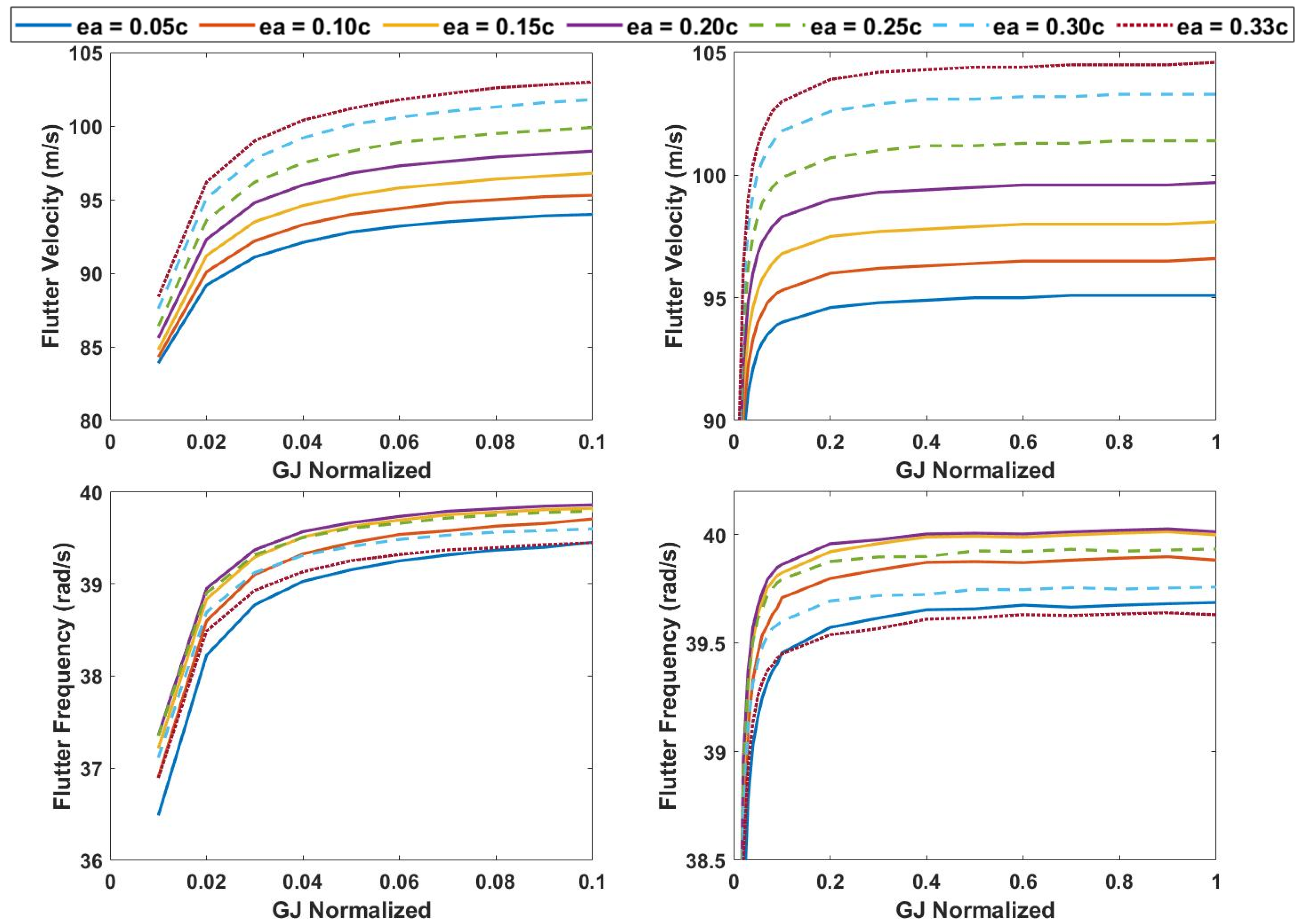
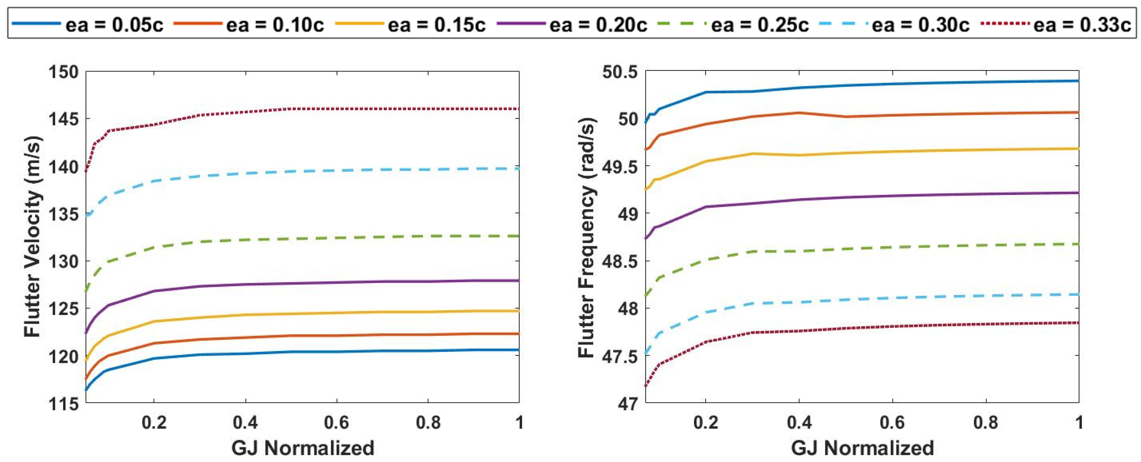
The effect of varying the outboard segment center of gravity on the aeroelasticity of the ASAPP wing is analyzed by moving the cg towards the leading edge at the 33% chordwise position. Aeroelastic analysis is performed to evaluate the change in flutter boundaries of the wing due to the change in cg from 43% to 33% chordwise position. The flutter velocity and frequency for the three wingspan cases—0%, 25%, and 50%—are calculated for torsional rigidities of 5% of baseline configuration and higher, and the results are presented in Figure 16, Figure 17 and Figure 18. A significant increase in the flutter velocity is evident for all the span lengths as compared to the previous case of identical cg position for the inboard and outboard sections.
The highest flutter velocity is observed for the 33% ea position for all three cases, which corresponds to the coincident center of gravity and elastic axis for the outboard wing section. However, for the wing without span extension, the second highest flutter velocity is observed for the most forward ea position for torsional rigidity of up to 70% of the baseline configuration, following which the 30% ea case exhibits slightly greater value, as shown in Figure 16. There is a 14.8% increase in flutter velocity for the forward cg case as compared to the identical cg case at the lowest ea position, whereas a 19% increase from the baseline configuration is evident.
The flutter velocity and frequency show a similar pattern for the higher torsional rigidity cases as compared to the identical cg position case, as is evident from Figure 17 and Figure 18. However, both wing lengths exhibit significant elevation in flutter velocities, the change being a 7.4% increase for 25% span extension and a 10.4% increase for the 50% span extension case at the lowest elastic axis position. For 25% span extension, the highest flutter frequency is observed for the lowest elastic axis position, which progressively decreases as the elastic axis is moved backward toward the trailing edge. For the 50% span extension case, the 10% and 15% ea position cases show greater flutter frequency than the 5% ea position case, which has approximately the same flutter frequency as the 20% ea position case, followed by the 30% and 33% ea positions.
3.5. Gust Load Analysis
A gust load analysis is performed to quantify the load alleviation properties of the pitch twist mechanism. A quasi-static gust load analysis is performed to calculate root bending moment and root shear force for various values of gust gradient, H, ranging from 9.144 to 106.7. A quasi-steady form of Theodorsen’s model is utilized for the calculation of aerodynamic forces by setting the Theodorsen’s transfer function, C(k), as 1. The analyses are performed for 0% and 25% span extension.
Quasi-Steady Analysis
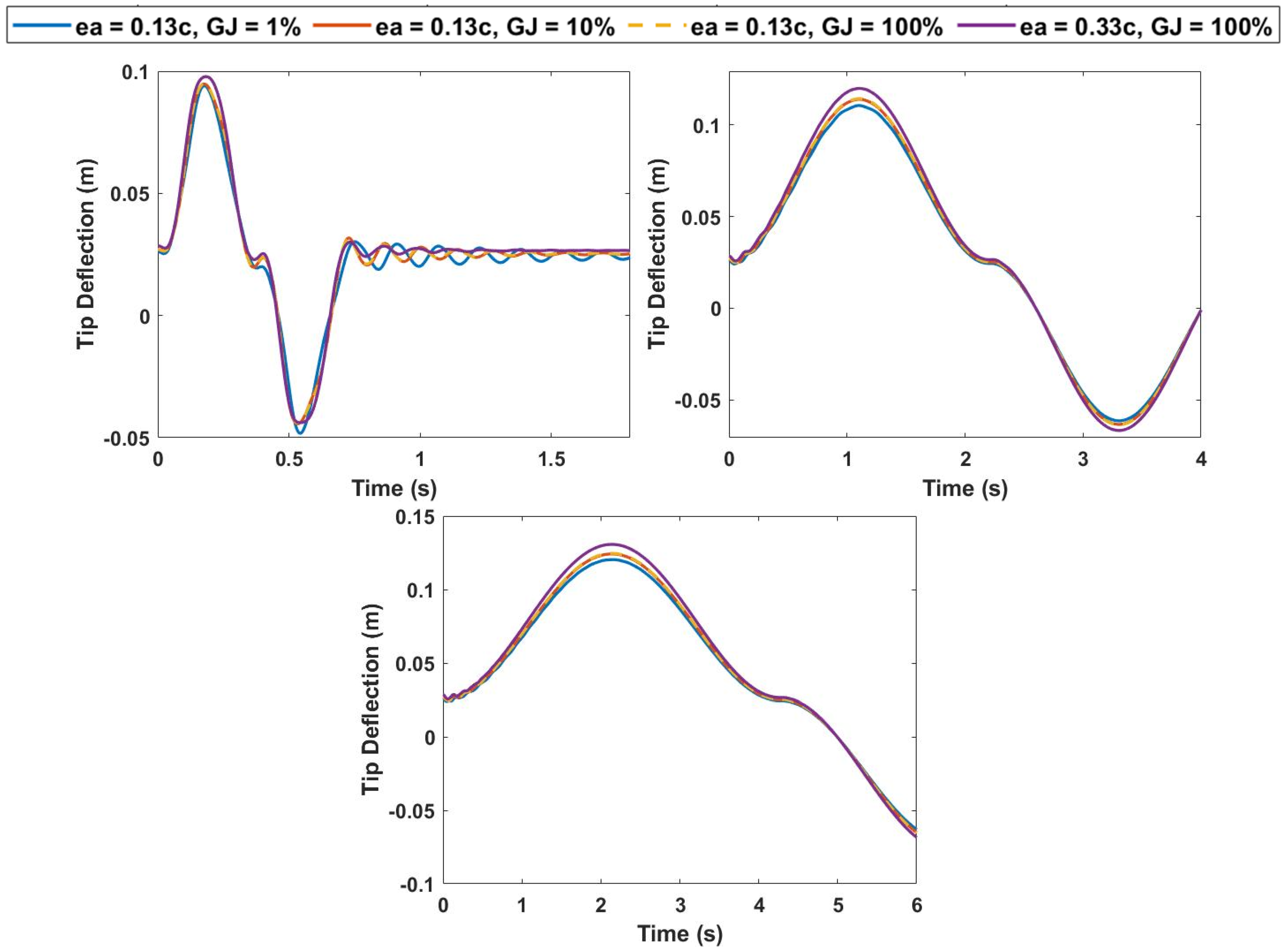
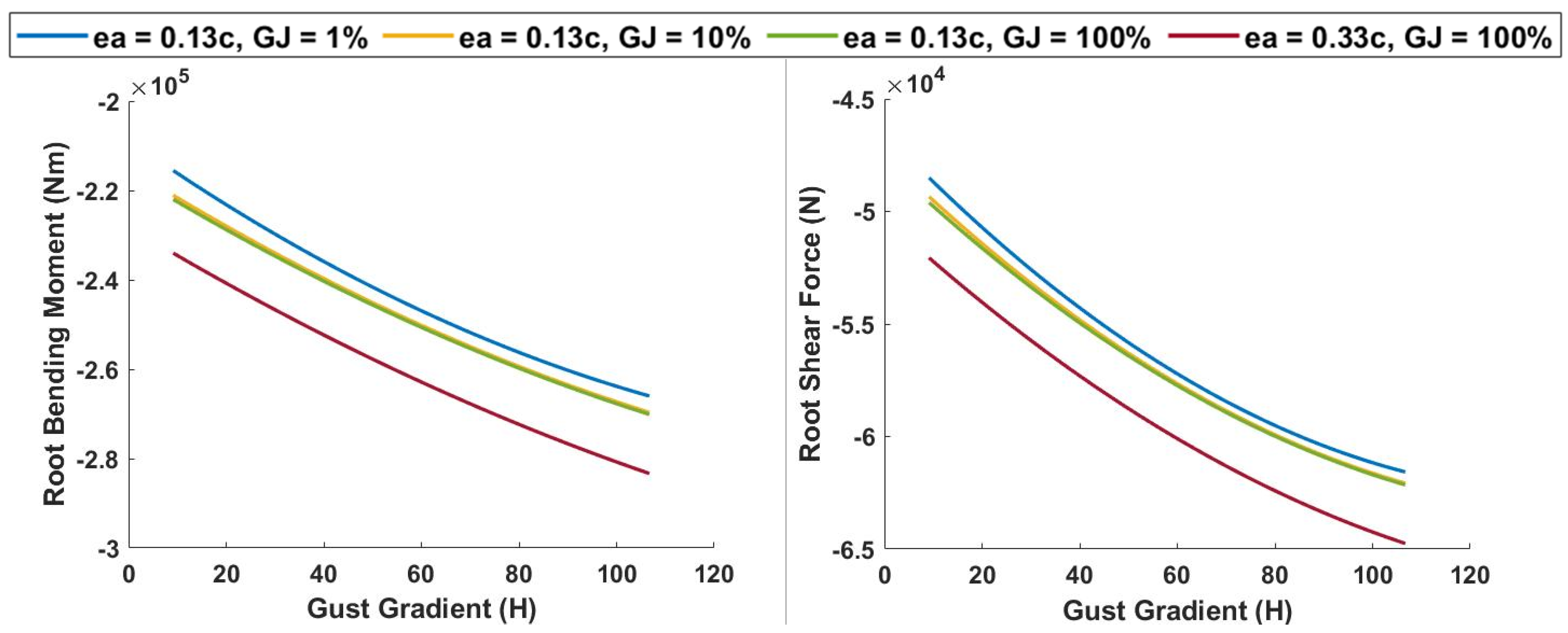
For the analysis, the angle of attack is set as 5 degrees at an airspeed of 50 m/s. The elastic axis position is fixed at between 13% of the chord, while the outboard rotational spring torsional rigidity is varied between 1%, 10%, and 100% of the reference value. A quasi-steady analysis is considered by setting Theodorsen’s transfer function to 1. The results for tip deflection for 0% and 25% span extension are presented. Root bending moment and root shear force are calculated at the point of maximum positive and negative tip deflection with variation in gust gradient (H). For the reference wing configuration, the tip deflection of 0.1307 m is calculated for a gust gradient of 106.7 m, with a root bending moment and root shear force of −1.37 × 10⁵ Nm and −4.23 × 10⁴ N, respectively. As is evident from Figure 19 and Figure 20, the ASAPP wing exhibits reduced loads for the considered values of outboard spring torsional rigidity. For 1%, 10%, and 100% value of torsional rigidity, the tip deflection is 8%, 5%, and 4.6% lower than the reference values, respectively. Similarly, the root bending moment and root shear forces are 6.9% and 5% lower at the lowest elastic axis position compared to the reference configuration.
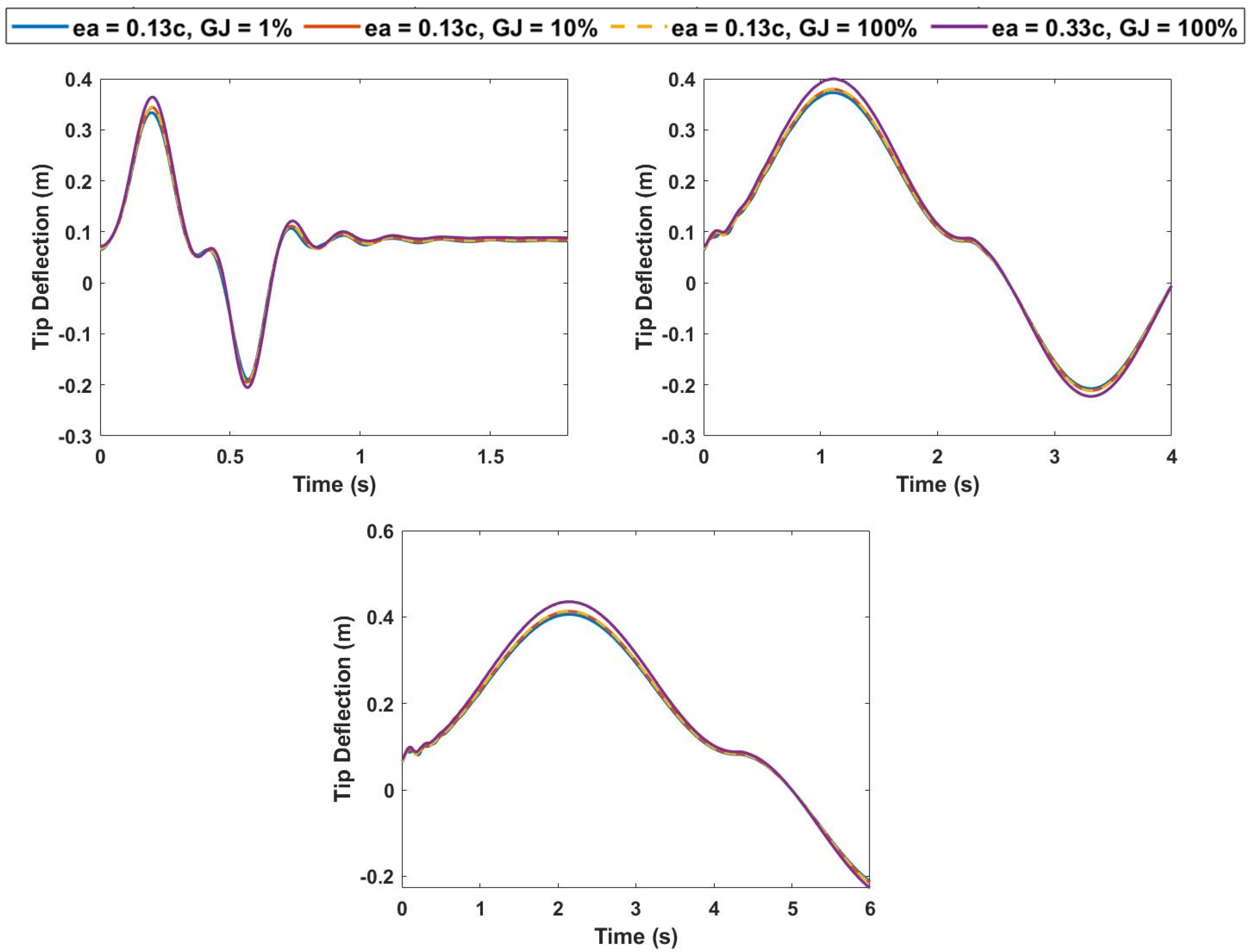
A 25% increase in span leads to greater tip deflection and wing loads, as is evident from Figure 21 and Figure 22. For the highest gust gradient, a 67% increase in tip deflection is noted for minimum torsional rigidity. However, this increase is 6.7% lower than the encountered deflection for an increase in span without the passive pitching mechanism. Similarly, an increase of 94% in root bending moment and 45.3% root shear force is exhibited for the augmented span configuration at minimum ea in comparison to the baseline wing. For a wing with a similar wingspan, the ASAPP wing exhibits a decrease of 6.5% and 5% in root bending moment and root shear force, respectively.
4. Cubic Nonlinearities
Conventional aeroelastic methods rely on linear approximations of structural and aerodynamic properties to determine static and dynamic aeroelastic boundaries and have been used to date with much success. However, there are inherent nonlinearities present in aerospace systems [29], which become critical under certain flight conditions. These could result from aerodynamic causes, such as unsteady aerodynamic phenomena, flow separations, shock formation, etc., or structural sources, such as large deflections, degradation of structural integrity, or loss of control surface. Woolston et al. [30,31] conducted one of the first studies regarding structural non-linearity using cubic springs in two-dimensional systems to investigate their effect on aeroelastic flutter. The cubic spring was modeled using an analog computer and validated with wind-tunnel experimentation. A good correlation was found between the developed model and experimental results. The results highlighted the sensitivity of flutter speed to initial disturbance in the system. Lee et al. investigated the aeroelastic effect of cubic softening and hardening springs in two-dimensional airfoil in incompressible flow [32]. The aeroelastic model was represented by eight first-order ordinary differential equations and solved using the fourth-order Runge–Kutta method. The results exhibited that softening springs were sensitive to initial disturbances, whereas the aeroelastic response was independent of the initial conditions for hardening springs. Divergent flutter did not occur, and limit-cycle oscillations appeared for velocities greater than the flutter velocity for linear spring. Lee and Leblanc [33] exhibited that cubic hardening springs experience limit-cycle oscillations instead of divergent flutter, whose amplitude increases with freestream velocity. Kim and Lee [34] analyzed the aeroelastic effect of freeplay nonlinearity in pitch and plunge motion for a two-dimensional airfoil in transonic and low-supersonic flow regimes. Aerodynamics were modeled using 2-D Euler code, and aeroelastic equations were solved using numerical methods. It is observed that limit-cycle oscillations occur for much lower velocities than in the case of linear structural properties. It is also exhibited that dangerous dynamic instabilities can arise from even small freeplay angles. O’Neil et al. [35] introduced nonlinear behavior into a wing model mounted using a model support system that permits prescribed nonlinear stiffness characteristics. The results indicate that LCOs (for the non-linear case) have significantly lower amplitude than for the linear flutter case. The effect of initial conditions and structural damping on the aeroelastic characteristics of the system were also studied. The results showed good consonance with previous literature [31,33] and exhibited freestream velocity to be the dominant factor in determining LCO behavior regardless of initial conditions.
In the present study, a structural nonlinearity is introduced in the aeroelastic system by replacing the linear torsional spring adjoining the inboard and outboard wing section with a cubic nonlinear spring. Hardening and softening effects are considered for a range of freestream velocities. Theodorsen’s unsteady aerodynamic model is used to determine aerodynamic parameters, and the system of differential equations is solved using the Runge–Kutta method. The stiffness of the nonlinear cubic spring is defined as:
where Kspr is the torsional spring stiffness, θspr is the spring angle of twist, and C1 and C2 are cubic spring coefficients.
where C1 is equal to linear spring stiffness in the absence of nonlinearities (GJinit) and γ = C2/C1 corresponds to the degree of spring hardness or softness, positive for hardening and negative for softening spring. The torsional spring stiffness is incorporated into the finite element model and the system of equations is solved using the explicit Runge–Kutta (2,3) method.
4.1. Hardening Spring
The aeroelastic response of a cubic hardening spring is analyzed for 0% span extension at various freestream velocities. An external lift force for a 5-degree angle of attack at a freestream velocity of 50 m/s is applied and it is assumed that the system starts from rest. The elastic axis is fixed at 13% of chord and GJinit is fixed to be 10% of the baseline wing torsional rigidity.
4.1.1. Spring Hardening Response for 0% Span Extension
The response for tip deflection vs. time and phase portrait of tip twist rate vs. tip twist is given in Figure 23. At a velocity of 138.9 m/s and γ = 0 (linear spring), a limit-cycle oscillation (LCO) is observed, which corresponds to the flutter point. By increasing the spring hardness—increasing γ to 250—the flutter condition can be suppressed at the given velocity, as is evident from the stable, depleting oscillations. An increase in velocity to 139.9 m/s, at similar spring hardness, leads to divergent oscillations, which signify the crossing of the flutter boundary.
The spring hardness is increased from γ = 100—where the oscillations are unstable and divergent—up to γ = 1 × 10³, where behavior resembling an LCO can be observed from the system. This can also be observed in the phase portraits of Figure 24, where contained and thin lines of γ =1 × 10³ response demonstrate neither a converging nor a diverging scenario. A further increase in γ, to a value of 1 × 10⁴, makes the system stable, and the amplitude of the oscillations can be seen to be diminishing with time. For the condition of γ = 1 × 10⁴, the system is asymptotically stable, and this can further be corroborated by the converging lines of the phase portrait plot. The decrease in amplitude of oscillations demonstrates the potential of nonlinearities in preventing the onset of fatigue, which would otherwise be present in the structure due to cyclic loading at or above the flutter velocity.
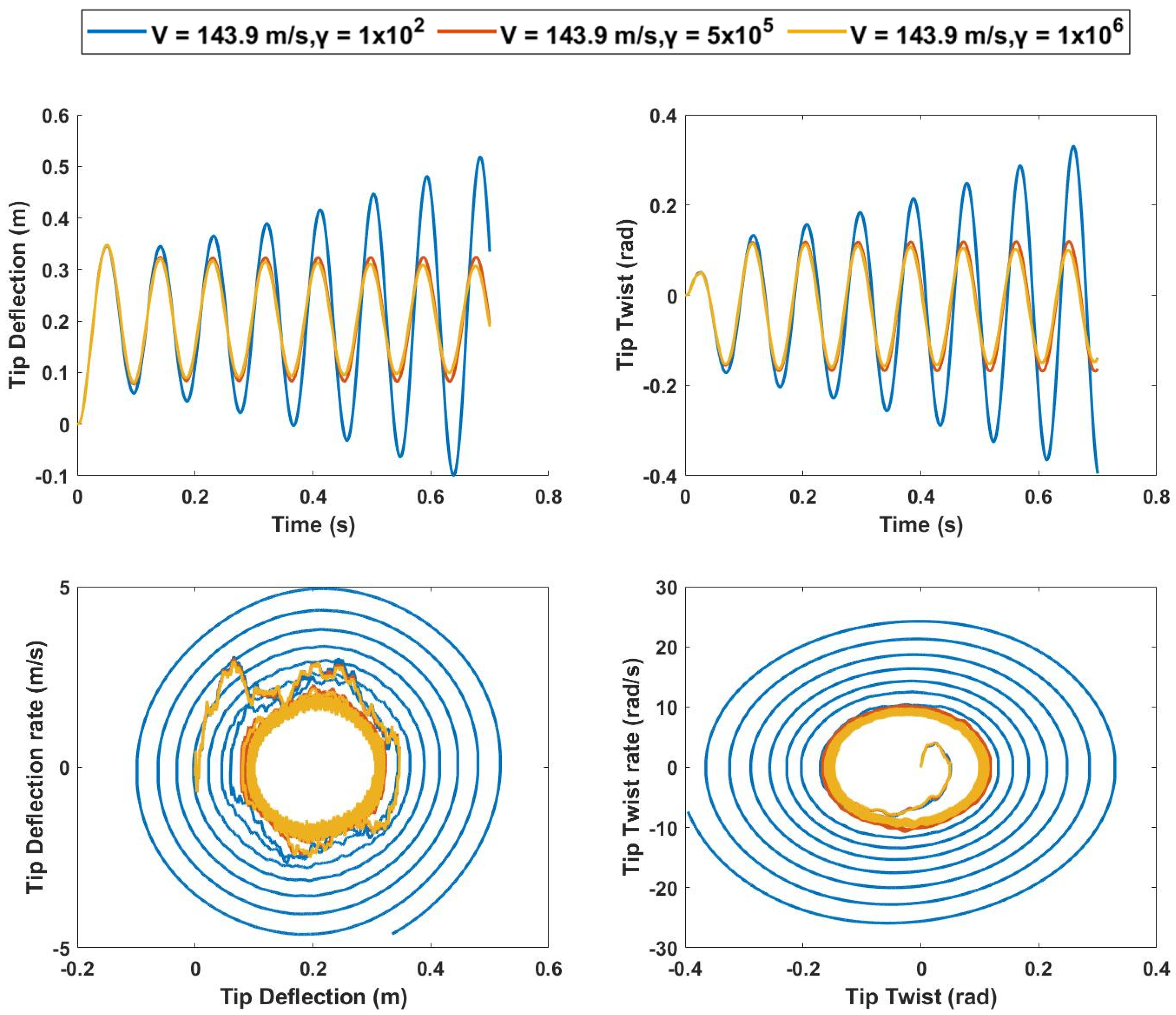
An increase in velocity to 143.9 m/s leads to significantly higher tip deflection and twist. At γ = 100, large divergent oscillations with asymptotically unstable phase portraits are evident. However, this condition can be limited, and flutter suppression can be achieved by increasing spring hardness, as shown in Figure 25. At γ = 5 × 10⁵ value, LCOs can be seen, and, at γ = 1 × 10⁶, the system exhibits decreasing amplitude and asymptotically stable phase plane behavior. However, it is worth noting that, for this velocity, 20 times increase in gamma from the LCO point results in only a marginal reduction in tip deflection.
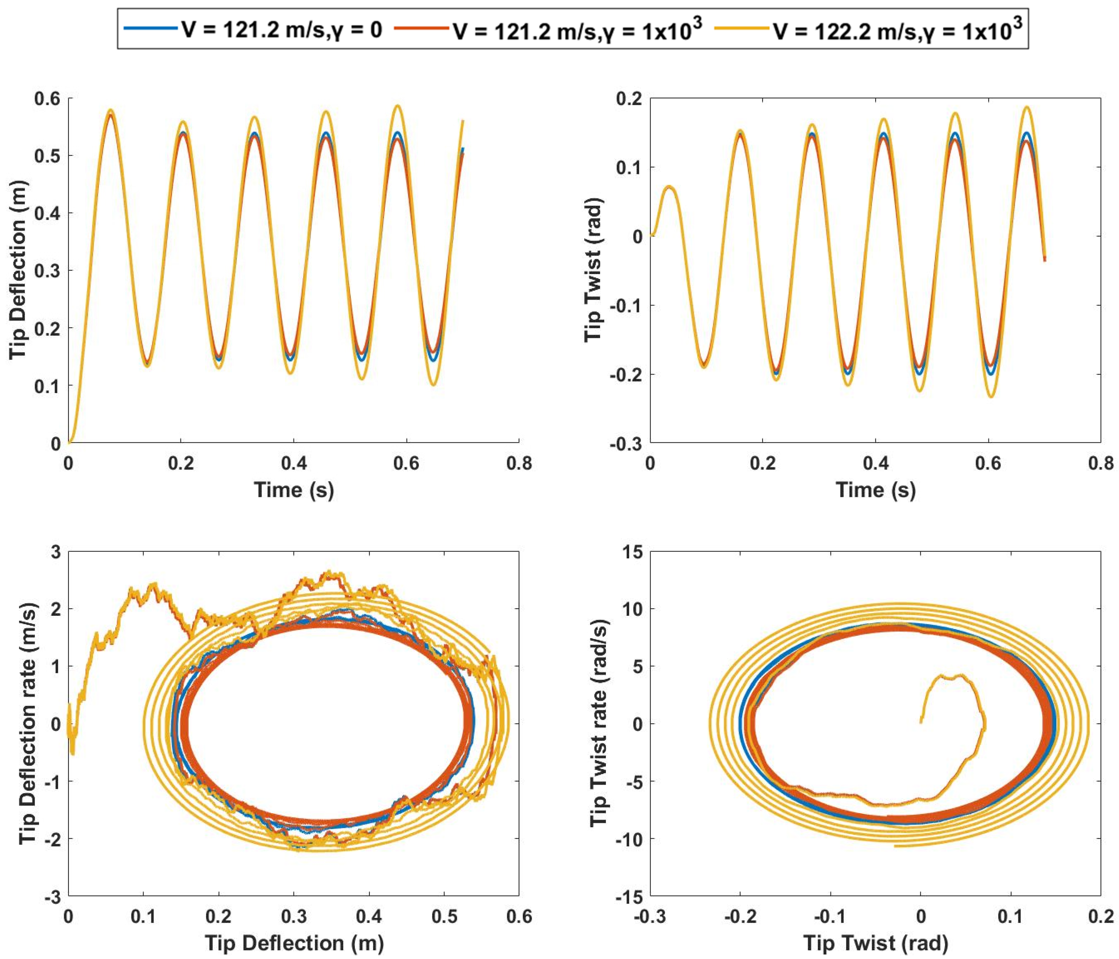
4.1.2. Spring Hardening Response for 25% Span Extension
The effect of cubic spring nonlinearity at a 25% span extension case is studied to estimate the effectiveness of introducing spring nonlinearity as a flutter suppression mechanism for span extended cases. The linear spring behavior at the flutter condition is represented by the γ = 0 condition in Figure 26, which can be observed from constant amplitude oscillation and a limit-cycle oscillation in the phase portrait plot, occurring at a velocity of 121.2 m/s for the given conditions. For a higher γ of 1 × 10³, a decrease in the amplitude of oscillation can be seen with an asymptotically stable phase plot. For a slight increase in velocity to 122.2 m/s, the system becomes unstable and divergent oscillations can be seen with a protruding phase plot.
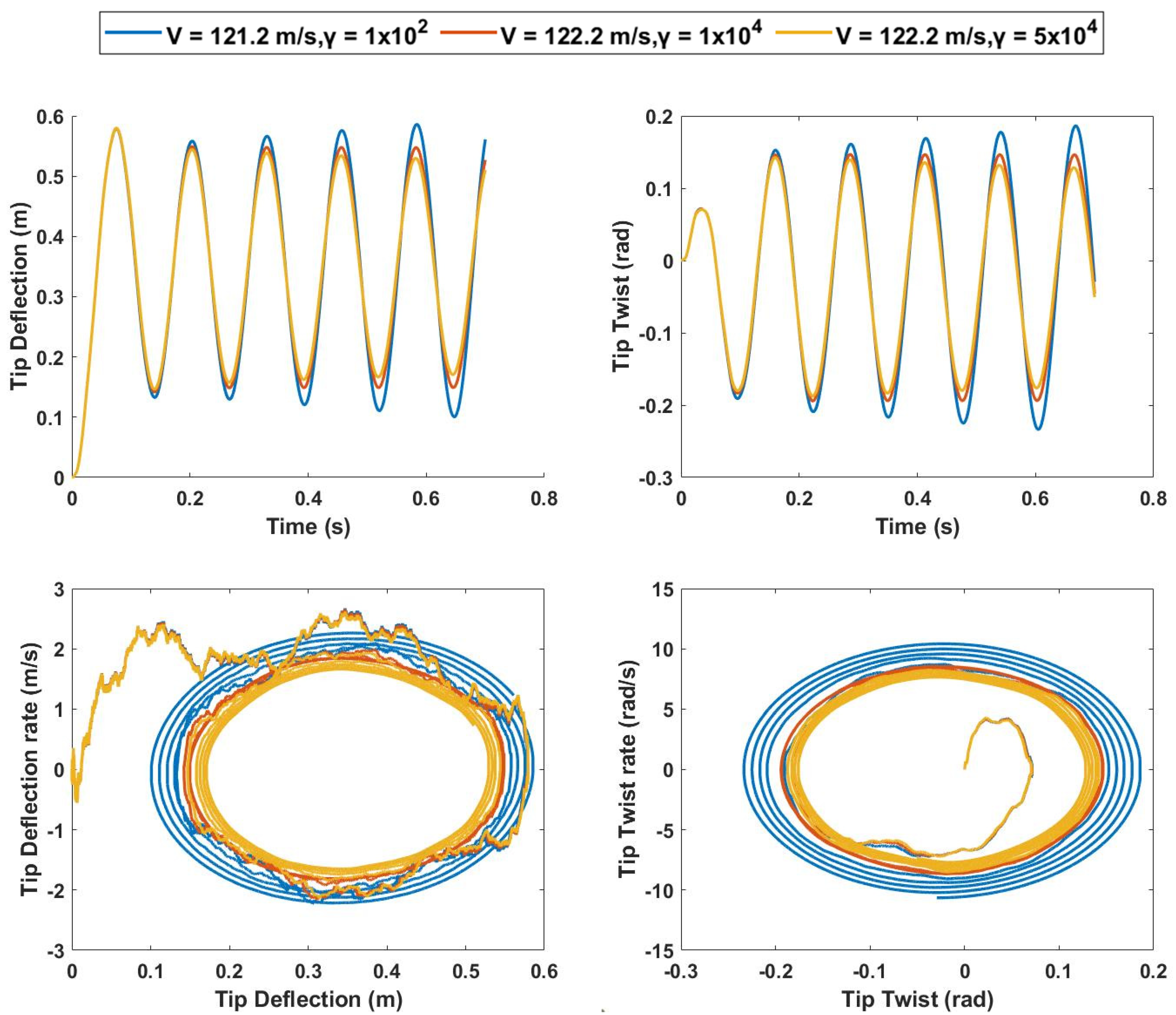
As the degree of hardness is further increased, a decrease in amplitude appears and LCOs occur for the value of γ = 1 × 10⁴, as shown in Figure 27. A further increase in γ leads to a reduction in amplitude of oscillations at a value of about 5 × 10⁴, suggesting a hardening spring can delay the flutter condition for the polymorphing ASAPP wing to a higher freestream velocity. The frequency of oscillations increases with an increase in torsional spring hardness and the magnitude of the LCO increases with an increase in freestream velocity.
4.2. Softening Spring
For the softening torsional spring analysis, the ASAPP wing configuration at 0% span extension, elastic axis at 13% of chord, and GJinit of 10% of inboard wing torsional rigidity are chosen. The analysis is carried out at various freestream velocities, at flutter point and below, and an external lift force for a 5-degree angle of attack is applied. The softening spring analysis is highly dependent on the initial conditions [30,31,33,35]; hence, for uniformity of condition for various γ and freestream velocities, the analysis is carried out from rest.
4.2.1. Spring Softening Response for 0% Span Extension
The linear case flutter condition for elastic axis position of 13% chord and 10% torsional spring rigidity is represented by γ = 0 case at a freestream velocity of 137.9 m/s. At a slightly low γ of −100, the amplitude of vibration decays with time and the phase portrait is asymptotically stable, as shown in Figure 28. As the degree of softness is increased to γ = −300, the amplitude of vibration increases, and the system starts to exhibit a very slight decrease in the amplitude of oscillation. However, any further increase in spring softness leads to abrupt, extremely high, and divergent oscillations.
A decrease in velocity to 133.9 m/s leads to a stable system for values of γ up to −400, as is seen in Figure 29. This is expected because, the further the velocity is dropped below the linear flutter velocity, the greater there is a spring softness requirement to cause instability. As the spring softness increases, there is a slight increase in the amplitude of vibration; however, no LCOs and the subtle onset of the unstable condition, such as in the previous case, are observed with increasing softness. Unlike the previous case, the system changes from being asymptotically stable to unstable and is characterized by large diverging oscillations with any further increase in spring softness beyond γ = −400.
It can be inferred from the data that the gradual onset of LCOs and flutter condition is only observed in neighboring values of linear flutter velocity for this span length. As the freestream velocity moves farther from linear flutter velocity, the change in spring softness results in an abrupt and divergent flutter condition occurring with huge amplitudes beyond a certain value of γ.
4.2.2. Spring Softening Response for 25% Span Extension
The effect of spring softening on the aeroelastic boundaries of a 25% span extended ASAPP wing is investigated, and the results are presented. At a slightly lower value than linear flutter velocity, the system is shown to be asymptotically stable with decreasing amplitude of vibrations, as shown in Figure 30. As spring softness increases, the amplitude of vibration increases up to the value of γ = −450, following which a sudden onset of violent divergent flutter is observed with huge amplitudes. Therefore, it can be stated that spring softening results in a hard divergent flutter, characterized by sudden and violent deflections that need to be considered in the design phase.
5. Conclusions
The aeroelasticity of the ASAPP polymorphing wing, capable of span extension of variable pitch/twist, was addressed. Firstly, a parametric analysis was carried out by modeling the wing using the finite element method based on the Euler–Bernoulli beam formulation. The developed aerodynamic solver was based on Theodorsen’s unsteady lift model using strip theory. The equations of motion were developed using the Lagrangian approach, and aeroelastic boundaries of flutter and divergence were estimated using the pk method. It is shown that it is possible to manipulate wing flutter and divergence phenomena by influencing the position of the elastic axis on the outboard wing section and the torsional rigidity of the spring adjoining the inboard and outboard wing section. The response of the polymorphing wing to discrete (1-cosine) gust was studied at various flight conditions, and a quasi-static analysis was performed at various torsional rigidity values of the outboard section to quantify the load alleviation properties of the polymorphing wing. Lastly, the effect of structural cubic nonlinearities on the aeroelastic response of the ASAPP wing was considered by replacing the linear torsional spring with a cubic nonlinear spring. Both hardening and softening effects were considered, and the aeroelastic response of the system due to nonlinearities was analyzed. It is evident from the analysis that the ASAPP wing exhibits superior aeroelastic performance to the baseline reference wing configuration, resulting in higher flutter and divergence velocity, with lower structural loads, such as root bending moment and root shear force. The position of the elastic axis plays a vital role, with improved aeroelastic and structural performance for positions ahead of the aerodynamic center for baseline span length case. However, the practical location of the elastic axis is limited by physical constraints, such as wing thickness and rotation mechanism dimensions. The position of the outboard wing center of gravity also significantly affects the flutter velocity for all the three span cases considered, resulting in a substantial increase as the center of gravity is moved forward. Torsional rigidity of the outboard pitching mechanism is a key variable for load alleviation, with lower root bending moment and root shear force encountered for minimum torsional rigidity values. However, little effect was observed for 10% and 100% torsional rigidity, which hints at a significant reduction in torsional rigidity for enhanced load alleviation capabilities. A trade-off is necessary between minimizing root loads at the wing structure and maximizing aeroelastic performance as the former is greatest for minimal torsional rigidity spring and the latter increases with higher torsional spring stiffness. Moreover, the nonlinear analysis suggests that hardening spring effects add to the damping of the system and delay the flutter condition to a higher freestream velocity. In contrast, spring softening causes instabilities to occur at a lower velocity and is characterized by the onset of a sudden hard flutter condition consisting of large deflections, which can prove to be extremely dangerous due to their abrupt nature and can lead to complete structural failure.
Author Contributions
Conceptualization, Z.H. and R.M.A.; methodology, Z.H. and R.M.A.; validation, Z.H. and R.M.A.; formal analysis, Z.H.; investigation, Z.H. and R.M.A.; resources, R.M.A.; data curation, Z.H.; writing—original draft preparation, Z.H.; writing—review and editing, Z.H., R.M.A. and L.S.; supervision, R.M.A. and L.S.; project administration, Z.H. and R.M.A.; funding acquisition, R.M.A. All authors have read and agreed to the published version of the manuscript.
Funding
The work presented herein has been funded by Abu Dhabi Education Council Award for Research Excellence Program (AARE 2019) through grant number AARE19-213.
Institutional Review Board Statement
Not applicable.
Informed Consent Statement
Not applicable.
Data Availability Statement
The data presented in this study are available on request from the corresponding author.
Acknowledgments
The work presented herein has been funded by Abu Dhabi Education Council Award for Research Excellence Program (AARE 2019) through grant number AARE19-213.
Conflicts of Interest
The authors declare no conflict of interest.
Nomenclature
| m’ | Mass per unit length |
| ρ | Density |
| ea | Elastic axis |
| cg | Center of gravity |
| w | Bending deflection |
| ϕ | Bending slope |
| t | Time |
| EI | Bending rigidity |
| GJ | Torsional rigidity |
| E | Young’s modulus |
| J | Torsional constant |
| l | Half span length of the wing |
| rα | Radius of gyration |
| θ | Angle of twist |
| Cw | Warping constant |
| Hb | Hermite’s cubic bending shape functions |
| Tt | Torsional shape functions |
| K | Stiffness matrix |
| M | Mass matrix |
| CL | Lift coefficient |
| C(k) | Theodorsen’s transfer function |
| Aerodynamic damping matrix | |
| Aerodynamic stiffness matrix | |
| A | Structural inertia matrix |
| D | Structural damping matrix |
| E | Structural stiffness matrix |
| B | Aerodynamic damping matrix |
| C | Aerodynamic stiffness matrix |
| q | Generalized coordinate |
Appendix A
The Hermite’s cubic shape functions are defined as:
The torsion shape function T1 and T2 are defined as:

Table A1.
Theodorsen theorem aerodynamic derivatives.
| Derivative | Expression |
|---|---|
References
- Concilio, A.; Dimino, I.; Lecce, L.; Pecora, R. Morphing Wing Technologies: Large Commercial Aircraft and Civil Helicopters; Butterworth-Heinemann: Oxford, UK, 2018. [Google Scholar]
- Barbarino, S.; Bilgen, O.; Ajaj, R.M.; Friswell, M.I.; Inman, D.J. A Review of Morphing Aircraft. J. Intell. Mater. Syst. Struct. 2011, 22, 823–877. [Google Scholar] [CrossRef]
- Directorate-General for Mobility and Transport; Directorate-General for Research and Innovation. Flightpath 2050—Publications Office of the EU. EU Publications. pp. 1–32. Available online: https://op.europa.eu/en/publication-detail/-/publication/296a9bd7-fef9-4ae8-82c4-a21ff48be673 (accessed on 10 March 2022).
- Weisshaar, T. Morphing Aircraft Technology-New Shapes for Aircraft Design. Multifunct. Struct. Integr. Sens. Antennas 2006, O1-1–O1-20. [Google Scholar]
- Rodrigue, H.; Cho, S.; Han, M.W.; Bhandari, B.; Shim, J.E.; Ahn, S.H. Effect of Twist Morphing Wing Segment on Aerodynamic Performance of UAV. J. Mech. Sci. Technol. 2016, 30, 229–236. [Google Scholar] [CrossRef]
- Ajaj, R.M.; Parancheerivilakkathil, M.S.; Amoozgar, M. Asapp: A Polymorphing Wing Capable of Active Span Extension and Passive Pitch. AIAA Scitech 2021, 2021, 0621. [Google Scholar]
- Okonkwo, P.; Smith, H. Review of Evolving Trends in Blended Wing Body Aircraft Design. Prog. Aerosp. Sci. 2016, 82, 1–23. [Google Scholar] [CrossRef]
- Bishop, W. The Development of Tailless Aircraft and Flying Wings. J. R. Aeronaut. Soc. 1961, 65, 799–806. [Google Scholar] [CrossRef]
- Aero-Isoclinic Wing and All-Moving Wing-Tips. Aircr. Eng. Aerosp. Technol. 1954, 26, 18. [CrossRef]
- Taylor, A.S. Manoeuvre Point Properties of the Aero-Isoclinic Wing. Aircr. Eng. Aerosp. Technol. 1952, 24, 257–262. [Google Scholar] [CrossRef]
- Andersen, G.R.; Cowan, D.L.; Piatak, D.J. Aeroelastic Modeling, Analysis and Testing of a Morphing Wing Structure. In Proceedings of the 48th AIAA/ASME/ASCE/AHS/ASC Structures, Structural Dynamics and Materials Conference, Honolulu, HI, USA, 23–26 April 2007. [Google Scholar]
- Muhammed, S.P.; Ajaj, R.M.; Khan, K.A. A Compliant Polymorphing Wing for Small UAVs. Chin. J. Aeronaut. 2020, 33, 2575–2588. [Google Scholar] [CrossRef]
- Alsulami, A.; Akbar, M.; Joe, W.Y. A Comparative Study: Aerodynamics of Morphed Airfoils Using CFD Techniques and Analytical Tools. In Proceedings of the ASME International Mechanical Engineering Congress and Exposition, Tampa, FL, USA, 3–9 November 2017; Volume 1, pp. 1–10. [Google Scholar] [CrossRef]
- Parancheerivilakkathil, M.S.; Haider, Z.; Ajaj, R.M.; Amoozgar, M. A polymorphing wing capable of span extension and variable pitch. Aerospace 2022, 9, 205. [Google Scholar] [CrossRef]
- Bae, J.S.; Seigler, T.M.; Inman, D.J. Aerodynamic and Static Aeroelastic Characteristics of a Variable-Span Morphing Wing. J. Aircr. 2005, 42, 528–534. [Google Scholar] [CrossRef]
- Neal, D.A.; Good, M.G.; Johnston, C.O.; Robertshaw, H.H.; Mason, W.H.; Inman, D.J. Design and Wind-Tunnel Analysis of a Fully Adaptive Aircraft Configuration. In Proceedings of the 45th AIAA/ASME/ASCE/AHS/ASC Structures, Structural Dynamics and Materials Conference, Palm Springs, CA, USA, 19–22 April 2004. [Google Scholar]
- Cooper, J.E.; Chekkal, I.; Cheung, R.C.M.; Wales, C.; Allen, N.J.; Lawson, S.; Peace, A.J.; Cook, R.; Standen, P.; Hancock, S.D.; et al. Design of a Morphing Wingtip. J. Aircr. 2015, 52, 1394–1403. [Google Scholar] [CrossRef]
- Miller, S.; Vio, G.A.; Cooper, J.E.; Vale, J.; Da Luz, L.; Gomes, A.; Lau, F.; Suleman, A.; Cavagna, L.; De Gaspari, A.; et al. SMorph–Smart Aircraft Morphing Technologies Project. In Proceedings of the 51th AIAA/ASME/ASCE/AHS/ASC Structures, Structural Dynamics and Materials Conference, Orlando, FL, USA, 12–15 April 2010. [Google Scholar] [CrossRef]
- Mei, C. Coupled vibrations of thin-walled beams of open section using the Finite Element Method. Int. J. Mech. Sci. 1970, 12, 883–891. [Google Scholar] [CrossRef]
- Ajaj, R.M.; Flores, E.I.S.; Amoozgar, M.; Cooper, J.E. A parametric study on the aeroelasticity of flared hinge folding wingtips. Aerospace 2021, 8, 221. [Google Scholar] [CrossRef]
- Bennamia, I.; Badereddine, A.; Zebbiche, T. Measurement of Vibrations of Composite Wings Using High-Order Finite Element Beam. J. Meas. Eng. 2018, 6, 143–154. [Google Scholar] [CrossRef]
- Theodorsen, T. General Theory of Aerodynamic Instability and the Mechanism of Flutter, NACA Report 496. Annu. Rep. Natl. Advis. Comm. Aeronaut. 1935, 268, 413. [Google Scholar]
- Brunton, S.L.; Rowley, C.W. Empirical state-space representations for Theodorsen’s lift model. J. Fluids Struct. 2013, 38, 174–186. [Google Scholar] [CrossRef]
- Fung, Y.C. An Introduction to the Theory of Aeroelasticity; Dover: New York, NY, USA, 2002. [Google Scholar]
- Hassig, H.J. An Approximate True Damping Solution of the Flutter Equation by Determinant Iteration. J. Aircr. 1971, 8, 885–889. [Google Scholar] [CrossRef]
- Ajaj, R.M.; Friswell, M.I. Aeroelasticity of Compliant Span Morphing Wings. Smart Mater. Struct. 2018, 27, 105052. [Google Scholar] [CrossRef]
- Patil, M.J.; Hodges, D.H.; Cesnik, C.E.S. Nonlinear Aeroelastic Analysis of Complete Aircraft in Subsonic Flow. J. Aircr. 2000, 37, 753–760. [Google Scholar] [CrossRef]
- Raghavan, B.; Patil, M.J. Flight Dynamics of High-Aspect-Ratio Flying Wings: Effect of Large Trim Deformation. J. Aircr. 2009, 46, 1808–1812. [Google Scholar] [CrossRef] [Green Version]
- Dowell, E.H.; Clark, R.; Cox, D.; Curtiss, H.C.; Edwards, J.W.; Hall, K.C.; Peters, D.A.; Scanlan, R.; Simiu, E.; Sisto, F.; et al. A Modern Course in Aeroelasticity; Springer: Berlin/Heidelberg, Germany, 2005. [Google Scholar]
- Woolston, D.S.; Runyan, H.L.; Andrews, R.E. An Investigation of Effects of Certain Types of Structural NonHnearities on Wing and Control Surface Flutter. J. Aeronaut. Sci. 1957, 24, 57–63. [Google Scholar] [CrossRef]
- Woolston, D.S.; Runyan, H.L.; Byrdsong, T.A. Some Effects of System Nonlinearities in the Problem of Aircraft Flutter; National Advisory Committee for Aeronautics: Washington, DC, USA, 1955.
- Lee, B.H.K.; Jiang, L.Y.; Wong, Y.S. Flutter of an Airfoil with a Cubic Nonlinear Restoring Force. In Proceedings of the 39th AIAA/ASME/ASCE/AHS/ASC Structures, Structural Dynamics and Materials Conference, Long Beach, CA, USA, 20–23 April 1998; Volume 1, pp. 237–257. [Google Scholar] [CrossRef]
- Lee, B.H.K.; LeBlanc, P. Flutter Analysis of a Two-Dimensional Airfoil with Cubic Non-Linear Restoring Force; BMT Limited: London, UK, 1986. [Google Scholar]
- Kim, D.H.; Lee, I. Transonic and Low-Supersonic Aeroelastic Analysis of a Two-Degree-of-Freedom Airfoil with a Freeplay Non-Linearity. J. Sound Vib. 2000, 234, 859–880. [Google Scholar] [CrossRef]
- O’Neil, T.; Gilliatt, H.; Strganac, T.W. Investigations of Aeroelastic Response for a System with Continuous Structural Nonlinearities. In Proceedings of the 37th AIAA/ASME/ASCE/AHS/ASC Structures, Structural Dynamics and Materials Conference, Salt Lake City, UT, USA, 15–17 April 1996. [Google Scholar] [CrossRef] [Green Version]
Figure 1.
Left: Westland Hill Pterodactyl I. Right: Short Sherpa Reprinted with permission from Ref. [8]. 1961, Cambridge University Press.
Figure 1.
Left: Westland Hill Pterodactyl I. Right: Short Sherpa Reprinted with permission from Ref. [8]. 1961, Cambridge University Press.

Figure 2.
ASAPP wing before (top) and after span extension (bottom) [6].
Figure 2.
ASAPP wing before (top) and after span extension (bottom) [6].

Figure 3.
ASAPP wing internal structure (left) and actuation mechanism (right) [10].
Figure 3.
ASAPP wing internal structure (left) and actuation mechanism (right) [10].

Figure 4.
Schematic of a wing undergoing bending and torsion [20].
Figure 4.
Schematic of a wing undergoing bending and torsion [20].
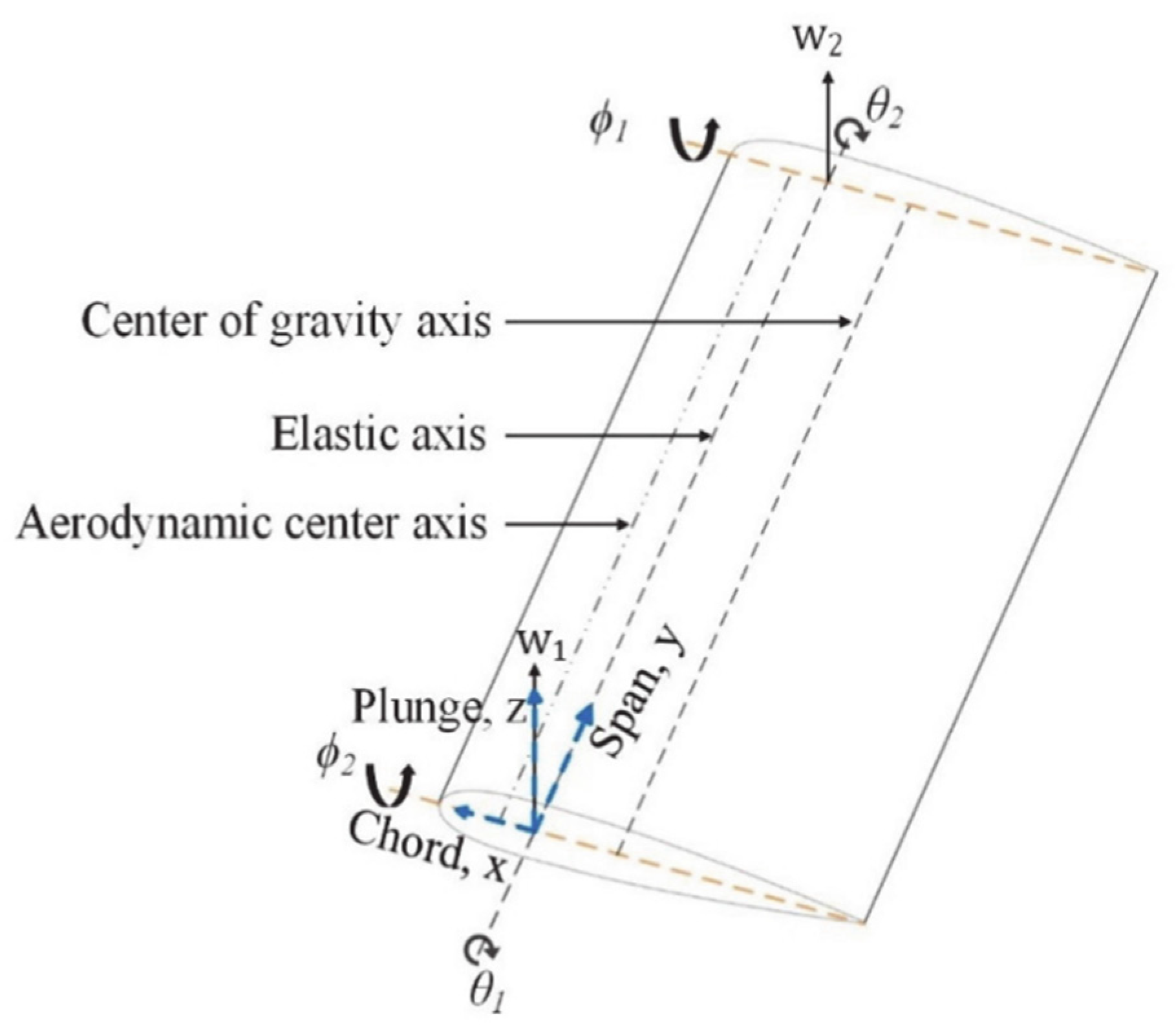
Figure 5.
Convergence study performed for the finite element model with 1 element for adjoining torsional spring and an equal number of elements for inboard and outboard wing sections.
Figure 5.
Convergence study performed for the finite element model with 1 element for adjoining torsional spring and an equal number of elements for inboard and outboard wing sections.

Figure 6.
Goland wing flutter modes for the first two bending and torsion modes.

Figure 7.
Top: Variation in flutter velocity against normalized torsional rigidity of spring. Middle: Variation in flutter frequency against normalized torsional rigidity of spring. Bottom: Variation in divergence velocity against normalized torsional rigidity of spring.
Figure 7.
Top: Variation in flutter velocity against normalized torsional rigidity of spring. Middle: Variation in flutter frequency against normalized torsional rigidity of spring. Bottom: Variation in divergence velocity against normalized torsional rigidity of spring.

Figure 8.
Left: Variation in root bending moment against normalized torsional rigidity of spring. Right: Variation in root shear force against normalized torsional rigidity of spring.
Figure 8.
Left: Variation in root bending moment against normalized torsional rigidity of spring. Right: Variation in root shear force against normalized torsional rigidity of spring.

Figure 9.
Wing twist at 5° angle of attack at 50 m/s velocity. Top left: GJ = 1% of reference value. Top right: GJ = 10% of reference value. Bottom: GJ = 100% of reference value.
Figure 9.
Wing twist at 5° angle of attack at 50 m/s velocity. Top left: GJ = 1% of reference value. Top right: GJ = 10% of reference value. Bottom: GJ = 100% of reference value.
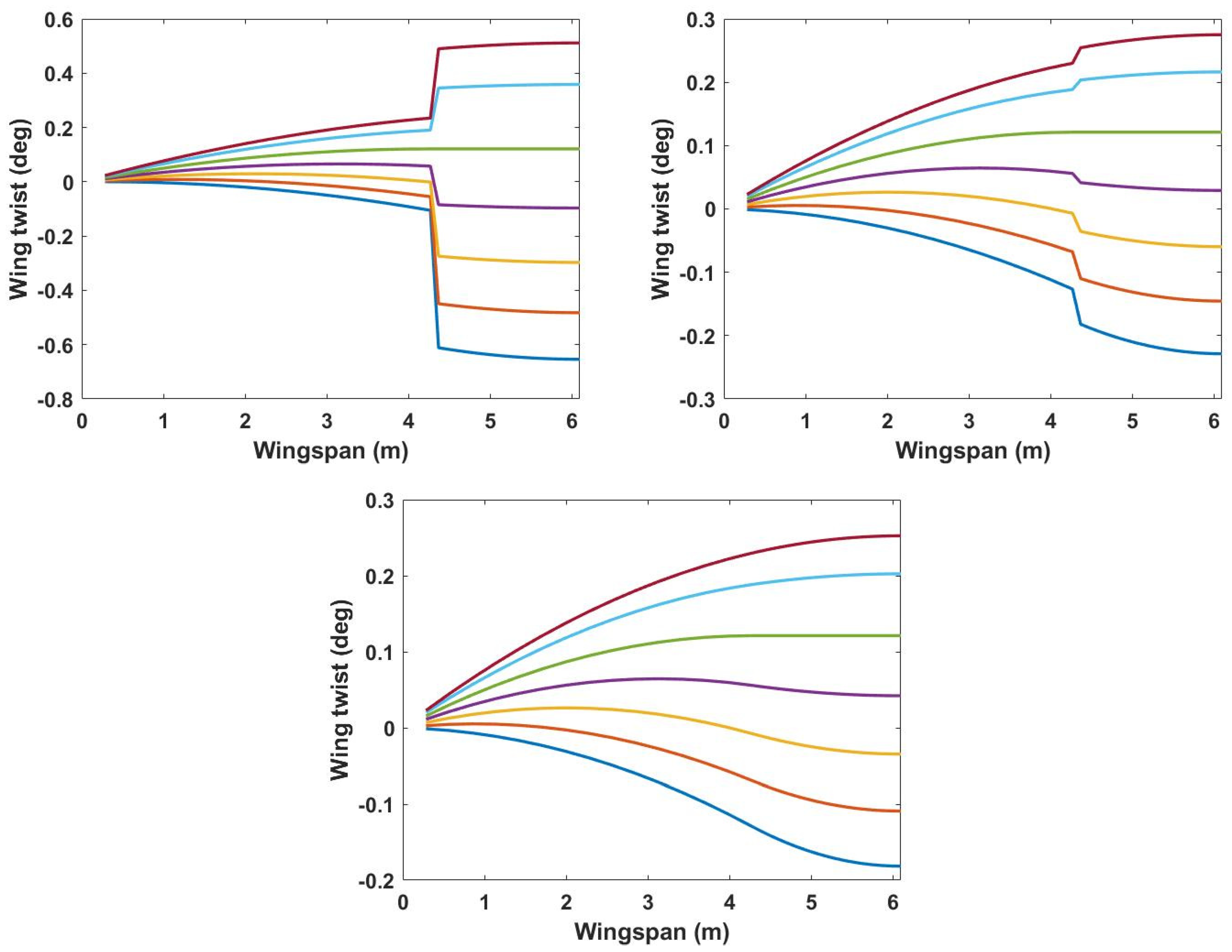
Figure 10.
Top: Variation in flutter velocity against normalized torsional rigidity of spring at 125% wingspan. Middle: Variation in flutter frequency against normalized torsional rigidity of spring. Bottom: Variation in divergence velocity against normalized torsional rigidity of spring at 125% wingspan.
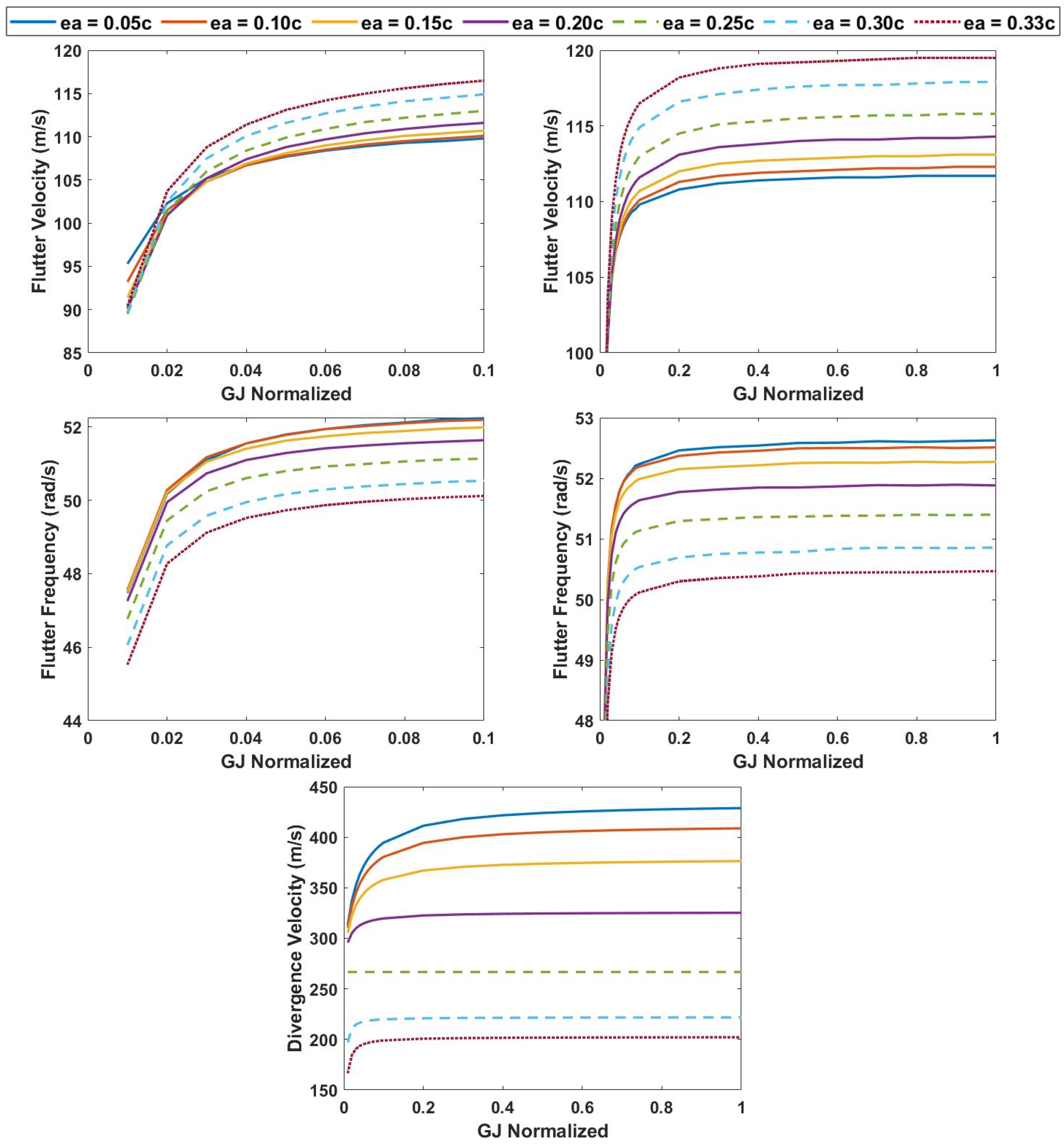
Figure 11.
Left: Variation in root bending moment against normalized torsional rigidity of spring at 125% wingspan. Right: Variation in root shear force against normalized torsional rigidity of spring at 125% wingspan.
Figure 11.
Left: Variation in root bending moment against normalized torsional rigidity of spring at 125% wingspan. Right: Variation in root shear force against normalized torsional rigidity of spring at 125% wingspan.

Figure 12.
Wing twist at 5° angle of attack at 50 m/s velocity at 25% span extension. Top left: GJ = 1% of reference value. Top right: GJ = 10% of reference value. Bottom: GJ = 100% of reference value.
Figure 12.
Wing twist at 5° angle of attack at 50 m/s velocity at 25% span extension. Top left: GJ = 1% of reference value. Top right: GJ = 10% of reference value. Bottom: GJ = 100% of reference value.
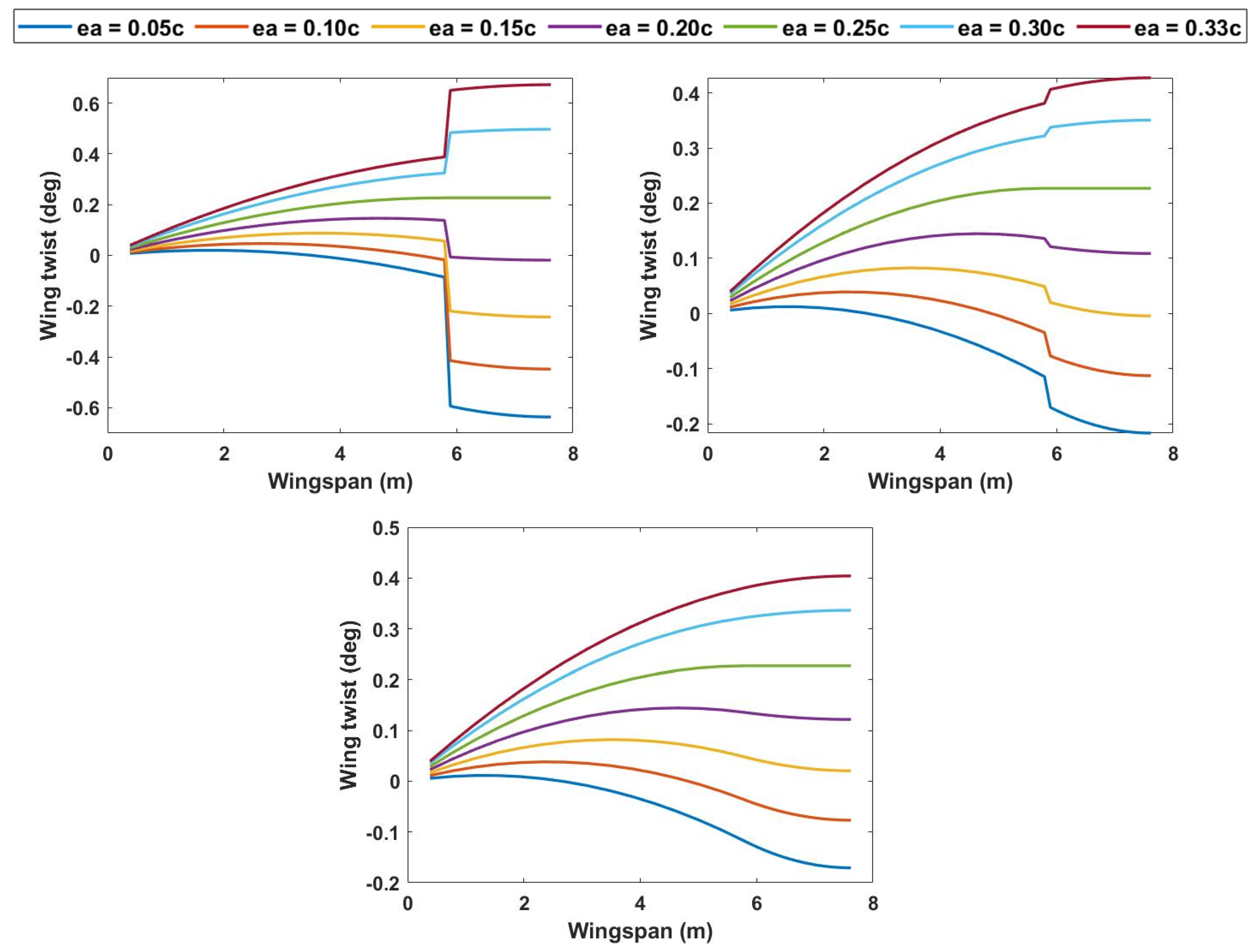
Figure 13.
Top: Variation in flutter velocity against normalized torsional rigidity of spring at 150% wingspan. Middle: Variation in flutter frequency against normalized torsional rigidity of spring at 150% wingspan. Bottom: Variation in divergence velocity against normalized torsional rigidity of spring at 150% wingspan.


Figure 14.
Left: Variation in root bending moment against normalized torsional rigidity of spring at 150% wingspan. Right: Variation in root shear force against normalized torsional rigidity of spring at 150% wingspan.
Figure 14.
Left: Variation in root bending moment against normalized torsional rigidity of spring at 150% wingspan. Right: Variation in root shear force against normalized torsional rigidity of spring at 150% wingspan.

Figure 15.
Wing twist at 5° angle of attack at 50 m/s velocity at 50% span extension. Top left: GJ = 1% of reference value. Top right: GJ = 10% of reference value. Bottom: GJ = 100% of reference value.
Figure 15.
Wing twist at 5° angle of attack at 50 m/s velocity at 50% span extension. Top left: GJ = 1% of reference value. Top right: GJ = 10% of reference value. Bottom: GJ = 100% of reference value.

Figure 16.
Left: Flutter velocity vs. GJ normalized without span extension. Right: Flutter frequency vs. GJ normalized without span extension.
Figure 16.
Left: Flutter velocity vs. GJ normalized without span extension. Right: Flutter frequency vs. GJ normalized without span extension.
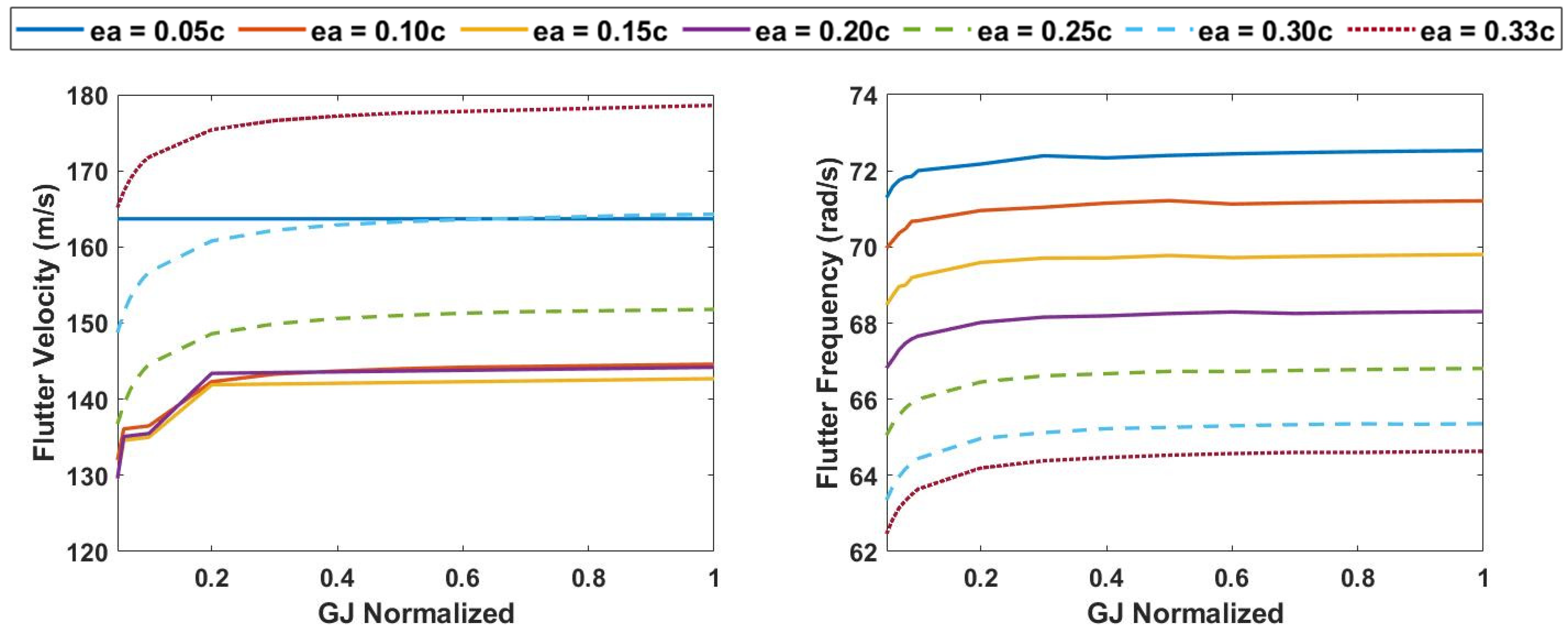
Figure 17.
Left: Flutter velocity vs. GJ normalized at 25% span extension. Right: Flutter frequency vs. GJ normalized at 25% span extension.
Figure 17.
Left: Flutter velocity vs. GJ normalized at 25% span extension. Right: Flutter frequency vs. GJ normalized at 25% span extension.

Figure 18.
Left: Flutter velocity vs. GJ normalized at 50% span extension. Right: Flutter frequency vs. GJ normalized at 50% span extension.
Figure 18.
Left: Flutter velocity vs. GJ normalized at 50% span extension. Right: Flutter frequency vs. GJ normalized at 50% span extension.
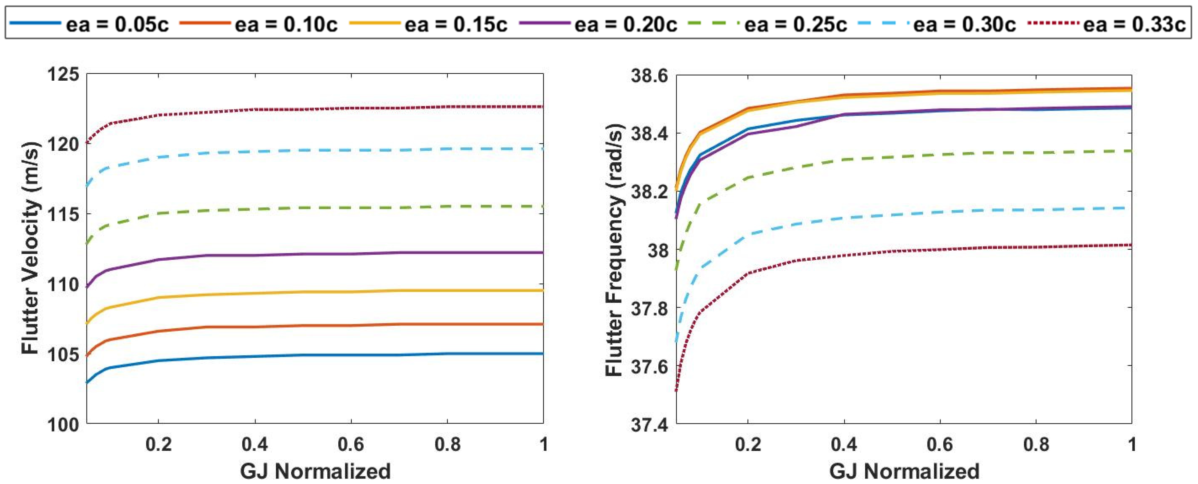
Figure 19.
Tip deflection without span increase vs. time. Top Left: H = 9.144. Top Right: H = 55. Bottom: H = 106.7. (Blue: GJ = 1%, Red: GJ = 10%, Dashed Yellow: GJ = 100%).
Figure 19.
Tip deflection without span increase vs. time. Top Left: H = 9.144. Top Right: H = 55. Bottom: H = 106.7. (Blue: GJ = 1%, Red: GJ = 10%, Dashed Yellow: GJ = 100%).

Figure 20.
Left: Root bending moment without span increase vs. gust gradient. Right: Root shear force without span increase vs. gust gradient. (Blue: GJ = 1%, Yellow: GJ = 10%, Green: GJ = 100%).
Figure 20.
Left: Root bending moment without span increase vs. gust gradient. Right: Root shear force without span increase vs. gust gradient. (Blue: GJ = 1%, Yellow: GJ = 10%, Green: GJ = 100%).

Figure 21.
Tip deflection at 25% span extension vs. time. Top Left: H = 9.144. Top Right: H = 55. Bottom: H = 106.7. (Blue: GJ = 1%, Red: GJ = 10%, Dashed Yellow: GJ = 100%).
Figure 21.
Tip deflection at 25% span extension vs. time. Top Left: H = 9.144. Top Right: H = 55. Bottom: H = 106.7. (Blue: GJ = 1%, Red: GJ = 10%, Dashed Yellow: GJ = 100%).

Figure 22.
Left: Root bending moment at 25% span extension vs. gust gradient. Right: Root shear with 25% span increase vs. gust gradient. (Positive gust: Blue: GJ = 1%, Yellow: GJ = 10%, Green: GJ = 100%).
Figure 22.
Left: Root bending moment at 25% span extension vs. gust gradient. Right: Root shear with 25% span increase vs. gust gradient. (Positive gust: Blue: GJ = 1%, Yellow: GJ = 10%, Green: GJ = 100%).

Figure 23.
Top: Left: Tip deflection vs. time response. Right: Tip twist vs. time response. Bottom: Left: Phase portrait of tip deflection rate vs. tip deflection. Right: Tip twist rate vs. tip twist.
Figure 23.
Top: Left: Tip deflection vs. time response. Right: Tip twist vs. time response. Bottom: Left: Phase portrait of tip deflection rate vs. tip deflection. Right: Tip twist rate vs. tip twist.

Figure 24.
Top: Left: Tip deflection vs. time response. Right: Tip twist vs. time response. Bottom: Left: Phase portrait of tip deflection rate vs. tip deflection. Right: Tip twist rate vs. tip twist.
Figure 24.
Top: Left: Tip deflection vs. time response. Right: Tip twist vs. time response. Bottom: Left: Phase portrait of tip deflection rate vs. tip deflection. Right: Tip twist rate vs. tip twist.
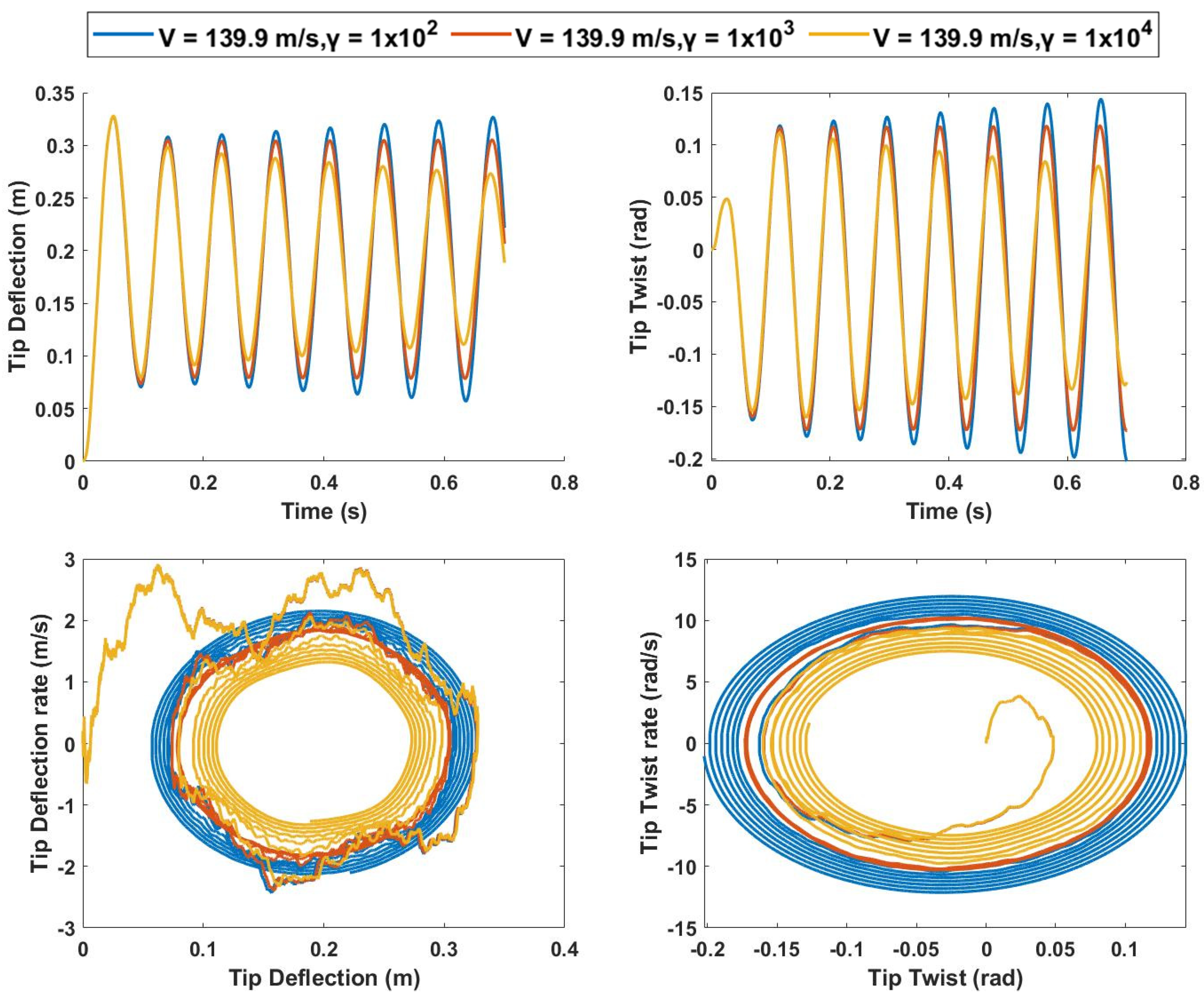
Figure 25.
Top: Left: Tip deflection vs. time response. Right: Tip twist vs. time response. Bottom: Left: Phase portrait of tip deflection rate vs. tip deflection. Right: Tip twist rate vs. tip twist.
Figure 25.
Top: Left: Tip deflection vs. time response. Right: Tip twist vs. time response. Bottom: Left: Phase portrait of tip deflection rate vs. tip deflection. Right: Tip twist rate vs. tip twist.

Figure 26.
Top: Left: Tip deflection vs. time response. Right: Tip twist vs. time response. Bottom: Left: Phase portrait of tip deflection rate vs. tip deflection. Right: Tip twist rate vs. tip twist.
Figure 26.
Top: Left: Tip deflection vs. time response. Right: Tip twist vs. time response. Bottom: Left: Phase portrait of tip deflection rate vs. tip deflection. Right: Tip twist rate vs. tip twist.

Figure 27.
Top: Left: Tip deflection vs. time response. Right: Tip twist vs. time response. Bottom: Left: Phase portrait of tip deflection rate vs. tip deflection. Right: Tip twist rate vs. tip twist.
Figure 27.
Top: Left: Tip deflection vs. time response. Right: Tip twist vs. time response. Bottom: Left: Phase portrait of tip deflection rate vs. tip deflection. Right: Tip twist rate vs. tip twist.

Figure 28.
Top: Left: Tip deflection vs. time response. Right: Tip twist vs. time response. Bottom: Left: Phase portrait of tip deflection rate vs. tip deflection. Right: Tip twist rate vs. tip twist.
Figure 28.
Top: Left: Tip deflection vs. time response. Right: Tip twist vs. time response. Bottom: Left: Phase portrait of tip deflection rate vs. tip deflection. Right: Tip twist rate vs. tip twist.

Figure 29.
Top: Left: Tip deflection vs. time response. Right: Tip twist vs. time response. Bottom: Left: Phase portrait of tip deflection rate vs. tip deflection. Right: Tip twist rate vs. tip twist.
Figure 29.
Top: Left: Tip deflection vs. time response. Right: Tip twist vs. time response. Bottom: Left: Phase portrait of tip deflection rate vs. tip deflection. Right: Tip twist rate vs. tip twist.
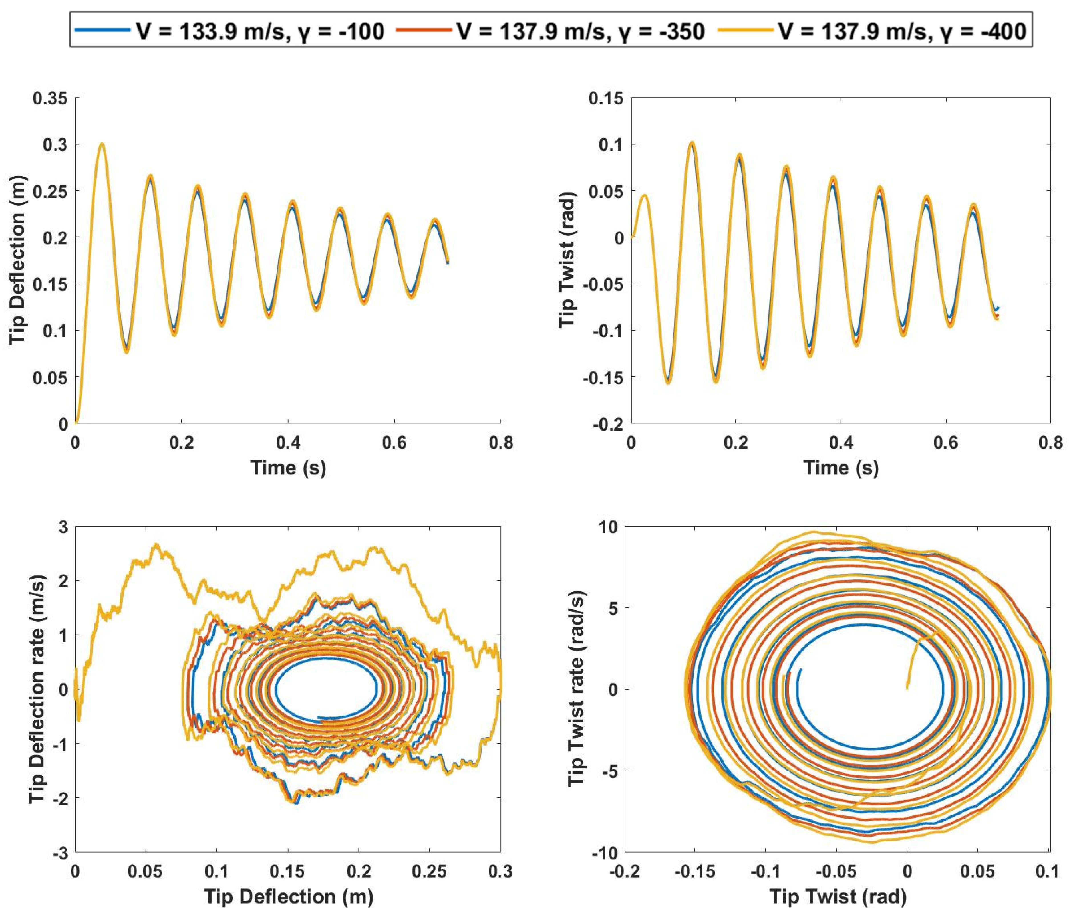
Figure 30.
Top: Left: Tip deflection vs. time response. Right: Tip twist vs. time response. Bottom: Left: Phase portrait of tip deflection rate vs. tip deflection. Right: Tip twist rate vs. tip twist.
Figure 30.
Top: Left: Tip deflection vs. time response. Right: Tip twist vs. time response. Bottom: Left: Phase portrait of tip deflection rate vs. tip deflection. Right: Tip twist rate vs. tip twist.
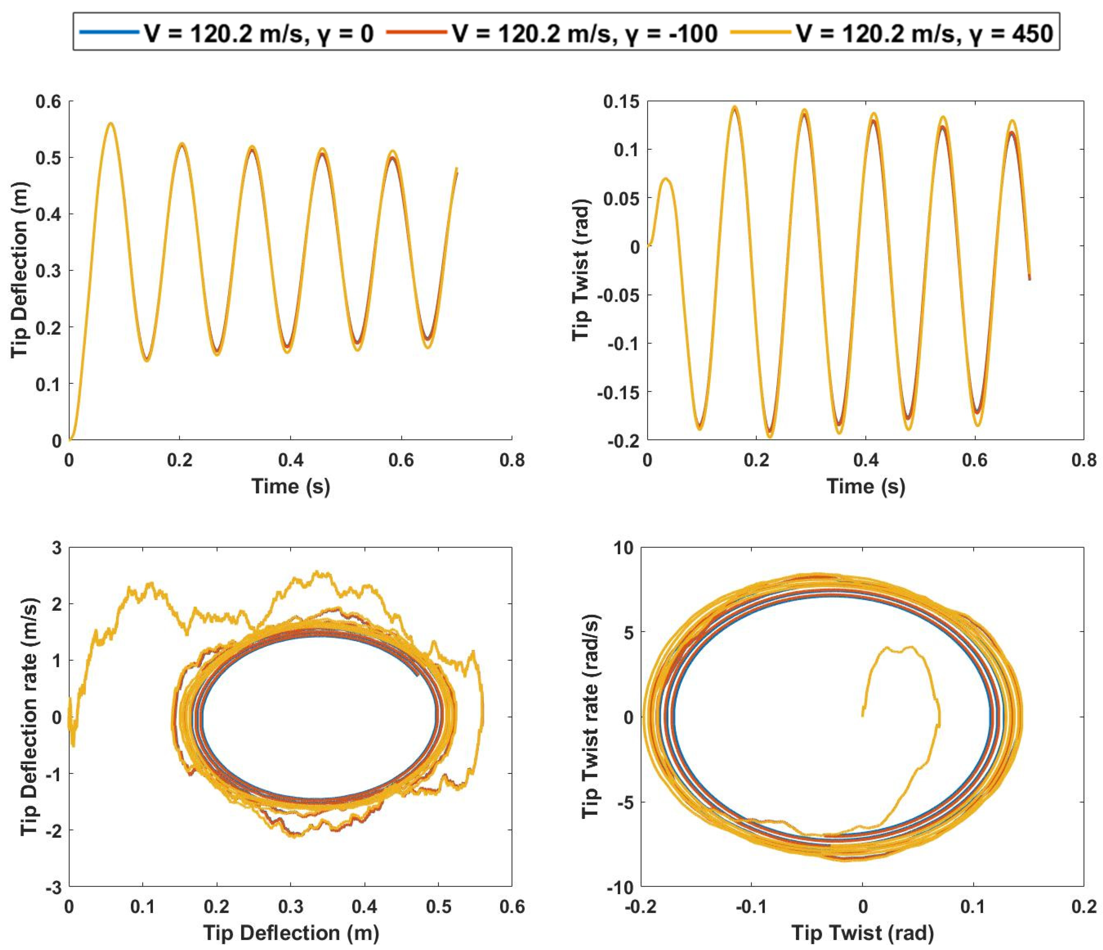
Table 1.
Properties of Goland wing.
| Specifications | Goland Wing |
|---|---|
| Half span (m) | 6.096 |
| Chord (m) | 1.8288 |
| Mass per unit length (m’) (kg/m) | 35.71 |
| Air density (ρ) (kg/m3) | 1.225 |
| Moment of inertia per unit length (kgm) around ea | 8.64 |
| Center of gravity (from leading edge) | 43% of chord |
| Elastic axis location (from leading edge) | 33% of chord |
| Flexural rigidity (EI) (Nm2) | 9.77 × 10⁶ |
| Torsional rigidity (GJ) (Nm2) | 9.87 × 10⁵ |
Table 2.
Comparison of calculated aeroelastic boundaries of Goland wing.
| Method | |||||
|---|---|---|---|---|---|
| Present Work | Ref. [20] | Ref. [26] | Ref. [27] | Ref. [28] | |
| Flutter Velocity (m/s) | 137.4 | 136.99 | 137.11 | 135.60 | 136.22 |
| Flutter Frequency (rad/s) | 69.351 | 69.97 | 69.90 | 70.20 | 70.06 |
| Divergence Speed (m/s) | 252.31 | 252.47 | 252.80 | - | 250.82 |
Table 3.
Span extension lengths of inboard and outboard wing sections.
| ASAPP Wing | Inboard Length (m) | Outboard Length (m) |
|---|---|---|
| Without span extension | 4.267 | 1.8288 |
| 25% span extension | 4.633 | 1.8288 |
| 50% span extension | 4.877 | 1.8288 |
Publisher’s Note: MDPI stays neutral with regard to jurisdictional claims in published maps and institutional affiliations. |
© 2022 by the authors. Licensee MDPI, Basel, Switzerland. This article is an open access article distributed under the terms and conditions of the Creative Commons Attribution (CC BY) license (https://creativecommons.org/licenses/by/4.0/).
Share and Cite
MDPI and ACS Style
Haider, Z.; Ajaj, R.M.; Seneviratne, L. On the Aeroelasticity of the Active Span and Passive Pitching Polymorphing Wing: A Parametric Study. Aerospace 2022, 9, 483. https://doi.org/10.3390/aerospace9090483
AMA Style
Haider Z, Ajaj RM, Seneviratne L. On the Aeroelasticity of the Active Span and Passive Pitching Polymorphing Wing: A Parametric Study. Aerospace. 2022; 9(9):483. https://doi.org/10.3390/aerospace9090483
Chicago/Turabian StyleHaider, Zawar, Rafic M. Ajaj, and Lakmal Seneviratne. 2022. "On the Aeroelasticity of the Active Span and Passive Pitching Polymorphing Wing: A Parametric Study" Aerospace 9, no. 9: 483. https://doi.org/10.3390/aerospace9090483
Note that from the first issue of 2016, this journal uses article numbers instead of page numbers. See further details here.