

Application of Modeling and Control Approaches of Piezoelectric Actuators: A Review

1
Department of Mechanical and Industrial Engineering, Manipal Institute of Technology, Manipal Academy of Higher Education, Manipal 576104, India
2
Department of Mechanical Engineering, National Institute of Technology Karnataka, Surathkal, P.O. Srinivasnagar, Mangalore 575025, India
*
Author to whom correspondence should be addressed.
Technologies 2023, 11(6), 155; https://doi.org/10.3390/technologies11060155
Submission received: 13 July 2023
/
Revised: 12 September 2023
/
Accepted: 27 September 2023
/
Published: 1 November 2023
(This article belongs to the Collection Electrical Technologies)
Abstract
:Piezoelectric actuators find extensive application in delivering precision motion in the micrometer to nanometer range. The advantages of a broader range of motion, rapid response, higher stiffness, and large actuation force from piezoelectric actuators make them suitable for precision positioning applications. However, the inherent nonlinearity in the piezoelectric actuators under dynamic working conditions severely affects the accuracy of the generated motion. The nonlinearity in the piezoelectric actuators arises from hysteresis, creep, and vibration, which affect the performance of the piezoelectric actuator. Thus, there is a need for appropriate modeling and control approaches for piezoelectric actuators, which can model the nonlinearity phenomenon and provide adequate compensation to achieve higher motion accuracy. The present review covers different methods adopted for overcoming the nonlinearity issues in piezoelectric actuators. This review highlights the charge-based and voltage-based control methods that drive the piezoelectric actuators. The survey also includes different modeling approaches for the creep and hysteresis phenomenon of the piezoelectric actuators. In addition, the present review also highlights different control strategies and their applications in various types of piezoelectric actuators. An attempt is also made to compare the piezoelectric actuator’s different modeling and control approaches and highlight prospects.
1. Introduction
The general requirement of precision motion in manufacturing and other commercial devices has led to extensive research and development in precision engineering. Having emerged as an integrated domain, precision engineering focuses on movement, measurement, and maintaining precision motion with higher accuracy and repeatability [1,2,3]. Piezoelectric actuators have been extensively used over the past few years as a source of precision positioning in a wide range of commercial applications. Piezoelectric actuators offer the advantage of precision motion in a few nanometers range to the tens of micrometer range. Furthermore, the faster response, low voltage actuation, high stiffness/load capacity/force generation smooth, backlash-free motion, non-magnetic actuation, wear resilience, cleanroom compatibility, vacuum, and cryogenic condition, low energy consumption adds to the advantages of the piezoelectric actuators [4,5,6]. Typical application domains of the piezoelectric actuators include precision manufacturing, fluidic applications, medical technology, micro-optics, aviation, defense, automation, robotics, aerospace, and consumer electronics.
Piezoelectric actuators are effectively employed in different applications such as micropumps/microreactors/micromixers [7,8], micromanipulators [9,10], microvalves [11], micro jet dispensers [12,13], atomic force microscopes [14,15], tool feed mechanisms [16,17], vibration isolation systems [18], etc. Piezoelectric actuators suffer from system nonlinearity when operated under dynamic conditions despite many advantages. The inherent hysteresis and creep limit the performance of the piezoelectric actuators under dynamic conditions, leading to nonlinearity in the system. Moreover, a badly damped system leads to undesirable vibrations, which add to the nonlinearity [4,19,20]. The present review aims to bring out different modeling and control approaches employed in recent years to overcome the nonlinearities in piezoelectric actuators. The organization of the review is as follows. Section 2 briefly highlights the different piezoelectric actuators used in commercial applications. Section 3 sheds light on the piezoelectric actuators’ modeling, control, and comprehensive modeling approach. Section 4 illustrates different methods of driving the piezoelectric actuators. Section 5 highlights the various methods, comparisons, and applications of charge-based control of the piezoelectric actuators. Section 6, Section 7 and Section 8 highlight various aspects of voltage-based control, emphasizing different hysteresis models, creep models, control methods, and applications. The review ends with a conclusion and scope for future work in Section 9. Figure 1 shows the organization of the current review.
2. Overview of the Piezoelectric Actuation System
Piezoelectric actuators are a class of electromechanical devices that convert electrical signals to precise, controllable displacement. Typically, piezoelectric actuators are made of a group of smart materials that possess the property of piezoelectricity due to electromechanical coupling, which produces electric charge or mechanical strain based on the input stimulus [21]. When subjected to an external force, the piezoelectric materials produce electric charges corresponding to the direct piezoelectric effect. The application of piezoelectric materials as precision actuators adopts the inverse piezoelectric effect, which develops mechanical strain based on the applied electric potential, which in turn produces precision motion [21,22,23]. The early stage of discovering piezoelectric materials constituted quartz, Rochelle salt, and tourmaline, producing a comparable piezoelectric effect. However, the commercial need for large-range precision motion led to the discovery of synthetic piezoelectric materials such as Lead Zirconium Titanate (PZT) [24], Barium Titanate (BaTiO3) [25], PVDF [26], ZnO [27], etc.
Figure 2 represents the basic configuration of the piezoelectric actuators used in different applications. The basic configuration of piezoelectric actuators is unimorph and bimorph, wherein the single-layer or two-layer piezo materials are bonded onto the metal substrate [28,29]. The unimorph and bimorph actuators are also available in a cantilever configuration, which is more flexible and produces a significant range of motion. However, the cantilever configuration lacks generated force [30,31]. The piezoelectric tube actuators can generate linear or lateral motion and are effectively adopted in many precision motion applications [32,33]. The multi-layered stacked configuration of the piezoelectric actuators can operate in linear or shear mode to produce linear or lateral precision motion. The range of motion developed by the stacked configuration is limited; however, the blocked force generated has an advantage over other types of actuators [5,21,34,35]. The amplified piezo actuators are developed with a flexural-compliant structural member to enhance the deflection of the stacked piezo actuators. Flexural-based amplification enhances the deflection range of the stacked actuators with moderate force [36,37]. Typically, the amplified piezo actuators in elliptical type, rhombus type, bridge type, symmetric five bar type, honeycomb type, Scott–Russell type, and lever type are extensively used in precision positioning applications [21,38,39,40,41].
Further advancement in piezoelectric actuator technology led to the development of stepping-piezoelectric actuators intended to generate a broader range of bi-directional linear and rotary motion. The stepping configuration of the piezoelectric actuators is also known as the piezo motor, which typically involves traditional piezoelectric actuators such as the unimorph/bimorph/multi-layered stacked actuators and the amplified piezo actuators as the primary source of actuation [21,42,43]. Inchworm piezoelectric motors [21,44,45], inertial piezoelectric motors [21,46,47], and ultrasonic piezoelectric motors [21,48,49] have been extensively reported in recent years which are effective in fulfilling the need of large range stepping motion. These piezoelectric motors can produce either linear/rotational motion or both, depending on the design and arrangement of the primary piezoelectric actuation mechanism. Researchers have also developed a series/parallel arrangement of multiple piezoelectric stepping stages to achieve multi-degree freedom linear/rotational motion along different coordinates [50,51]. A detailed review of different configurations of traditional, stepping, and multi-degree freedom piezoelectric actuators are presented in the works of Mohith et al. [21], Jianping Li et al. (2019) [52], Liang Wang et al. (2019) [53], and Shupeng Wang et al. (2019) [54].
The traditional piezoelectric actuators such as unimorph, bimorph, tube, and multi-layered actuators are a primary source of precision actuation in many commercial actuation systems. The constitutive Equations (1) and (2) represent the piezoelectric phenomena occurring in piezoelectric actuators is represented as follows [55] (IEEE Ultrasonics, Ferroelectrics, and Frequency Control Society)
where σ and ε correspond to the stress tensor and strain tensor, D and E correspond to the vector representing the electric displacement and the electric field, d represents the piezoelectric material constant, eE the elastic compliance matrix, ϵT represents the dielectric constant, i, j = 1, 2, 3, 4, 5, 6 and m, k = 1, 2, 3 refers to the different directions in the Cartesian coordinates. As observed in Equations (1) and (2), the mechanical strain developed in the piezoelectric materials follows a linear relationship with the applied electric field. However, when the piezoelectric actuators are put into operation under dynamic conditions, there exist system nonlinearities that affect the performance of the piezoelectric actuators. Therefore, there is a need for better modeling and control approaches that can model the inherent system nonlinearities of the piezoelectric actuation systems and minimize the error occurring due to nonlinearity through appropriate compensation models and control strategies.
3. Comprehensive Dynamic System Model and Modeling/Control Issues of the Piezoelectric Actuator
The promising potential of piezoelectric actuators has led to their application across wide ranges of precision manipulation to the extent of the nanometer scale. However, the dynamics of the piezoelectric actuator in specific applications lead to inherent nonlinearity that causes positioning errors. Thus, the development of modeling and control strategies for minimizing the nonlinearity errors in piezoelectric actuators have been given considerable attention. The constitutive relationship of piezoelectric materials (Equations (1) and (2)) does not account for any dynamic nonlinearity in the piezoelectric actuators. The nonlinearity emanates from hysteresis and creep, which significantly degrades the performance of the piezoelectric actuators in dynamic applications. Moreover, a badly damped system with piezoelectric actuation leads to dynamic vibrations, adding to the system’s nonlinearity [55,56].
Figure 3 represents the schematic of nonlinearity occurring in the piezoelectric actuators due to hysteresis, creep, and vibration. Hysteresis in the piezoelectric actuators occurs due to specific extrinsic contributions that induce nonlinearity between the actuation voltage and precision output displacement. The extent of hysteresis error depends on the present value of the input voltage and the previous history, thus developing a memory-based phenomenon. The amplitude and the frequency of the actuation signals majorly affect the extent of hysteresis error occurring under the dynamic operation of the piezoelectric actuators. Thus, the hysteresis in piezoelectric actuators shows either amplitude-dependent or rate-dependent behavior. The model approximating the hysteresis is either rate-dependent or rate-independent [56,57,58,59,60,61,62]. The piezoelectric actuators under dynamic operation experience hysteresis error of about 15%, but with the increase in the driving frequency of the actuation signal, the error can shoot up to almost 35%, thus leading to the error in precision motion [55].
The creep in the piezoelectric actuators occurs due to the effect of applied electric potential on the remnant polarization of the electric dipole. The root cause for creep drift is the realignment of the crystal structure on the application of the electric field. The effect of creep drift significantly occurs at a low speed of operation and leads to a broad range of nonlinearity with the increase in time [55,56]. The combined effect of hysteresis and creep hinders the performance of the piezoelectric actuators in precision positioning applications where higher accuracy and precision are the significant criteria [57,58,59,60,61,62]. Implementing an appropriate modeling approach can model the piezoelectric actuator system behavior under hysteresis and creep, which can provide suitable compensation by adopting proper control approaches to overcome the nonlinearity errors.
The piezoelectric actuators are modeled as a combination of electrical and mechanical systems based on the electromechanical interaction at different stages [63,64,65]. Figure 4 represents the schematic of the electromechanical model of the piezoelectric actuator. Goldfarb et al. [63] developed and implemented the following electromechanical model of the piezoelectric actuator with hysteresis nonlinearity. Adriaens et al. [64] also adopted a similar approach in defining the electromechanical model of the piezoelectric actuator with hysteresis. Gao et al. [63] proposed a linear modeling approach with the electromechanical interaction, which excluded the effect of nonlinearity occurring due to hysteresis.
Mathematically the comprehensive dynamic model of the piezoelectric actuator can be written as shown in Equations (3)–(9)
where Vapplied is the control voltage fed through a linear amplifier of gain Aamp, Ri is the overall resistance of the driving circuit. Vi is the amplified voltage that drives the piezo actuator, q and are the total charge and current through the circuit, H and T represent the hysteresis and electromechanical piezo coefficient with corresponding voltage drop VH, VT, and C corresponds to the total capacitance of the piezoelectric circuit which stores charge qc. The piezoelectric effect induces a charge of qP across the transformer element T. The conversion of the applied voltage across the piezoelectric element induces force FP with the piezoelectric element of mass mP, stiffness kP, and damping coefficient of bP, resulting in the displacement of xP.
4. Driving and Control Methods of Piezoelectric Actuators
Piezoelectric actuators are subject to inherent nonlinearities due to hysteresis, creep, and vibration. The extent of nonlinearity in the system could be controlled by driving the piezoelectric actuator. Figure 5 represents the control and driving approaches for piezoelectric actuators. Generally, actuators are either voltage-driven or charge-driven [58,60,66]. Both the charge-based and voltage-based control approaches of piezoelectric actuators effectively minimize the nonlinearity occurring in the piezoelectric actuators. However, both methods possess their disadvantages, which limit their applications. The basic principle of charge-based control considers effective control of charge applied to the piezoelectric actuator, thus controlling the internal electric field and resulting displacement. The voltage-based control adopts control of the piezoelectric actuator through appropriate modeling and control algorithms to eliminate the system’s nonlinearities. The following section presents the different methods of charge-based and voltage-based control of the piezoelectric actuators.
5. Charge-Based Control of Piezoelectric Actuators
The charge-driven mode effectively minimizes the dynamic nonlinearities occurring in the piezoelectric actuators due to hysteresis and creep effect. When supplied with an external electric field, the piezoelectric actuator behaves like a capacitor due to its dielectric property. Under dynamic operating conditions, the piezoelectric actuator behaves like a nonlinear capacitor. Thus, the charge across the piezoelectric actuator varies due to the nonlinear variation in capacitance of the piezoelectric actuator, which induces nonlinearity due to hysteresis and creep. The regulation of charge through control of current significantly reduces the nonlinearity due to hysteresis and creep [66].
From Equation (9), the input voltage Vi into the piezo actuator can be represented mathematically in terms of charge q(t) as shown in Equation (10)
where . From Equation (10), it is evident that the charge control of the piezoelectric actuator is independent of the hysteresis effect. Therefore, regulating the actuator capacitance by controlling the input current; therefore, the charge across the actuator results in substantial hysteresis and creep minimization. Thus, the charge input into the piezoelectric actuator gives almost a linear displacement with the minimum error [55,66,67]. The following section highlights the different approaches to charge-based control of the piezo actuators.
5.1. Capacitor Insertion
Under dynamic conditions, the application of time-varying voltage results in capacitance variation across the actuator due to the inherent dielectric properties of the piezoelectric material. This variation in the capacitance leads to variation in charge across the actuator, which induces hysteresis. Inserting a capacitor in series makes the piezoelectric actuator insensitivity to change in charge, limiting the hysteretic nonlinearity.
Figure 6 represents the schematic of the capacitor insertion method for charge-based control of piezoelectric actuators. From Figure 6,
where C, Cp corresponds to the capacitance of the inserted capacitor and the piezoelectric actuator with charge q and qp. From Equations (11) and (12), it is evident that the sensitivity decreases by a factor C/(C + Cp), which reduces the hysteresis loop due to the charge regulation across the piezo actuator by inserted capacitor C. Since the applied voltage from the source is divided between the inserted capacitor and the piezo actuator, the actual voltage available for actuation reduces, leading to a reduced range of motion. Thus, the capacitor insertion method requires a higher voltage source for achieving the same range of motion [66,68,69].
5.2. Time Controlled Current Amplification
The charge-based approach with current amplification is typically considered for high-dynamic applications. Figure 7 represents the schematic representation of the current amplification charge-based approach of the piezoelectric actuators. Since the integral of the charge on piezoelectric actuators represents the electric current, a current amplification can effectively be used as a source of charge control. In a real sense, the current amplification adopts a high gain voltage amplifier, which amplifies the input voltage, thus the input current [66]. As observed from Figure 7, the load current IL passes through the piezo actuator and the sensing resistor Rs to the ground.
Therefore, as shown in Equation (13),
The control circuit of the current amplification approach involves a voltage amplifier with gain factor ‘k’ with the input voltage Vin, which in turn controls the input current Iin. The implementation of a voltage amplifier with a close loop leads to Vin = VL, as shown in Equation (14)
Thus, with the implementation of a time-controlled current approach, the charge on the piezoelectric actuator can be amplified. A smaller value of the sensing resistor is adopted in the faster response of the actuator, whereas a higher value of the sensing resistor is used for precise positioning [66]. In addition, switching circuits can be implemented with the charge amplifier to control the direction of motion, rate of actuation, and precision motion achieved with the actuator [70,71].
5.3. Capacitor Based Sensing
Most of the charge amplifier used for the piezoelectric actuator adopts a secondary capacitor for sensing. Figure 8 represents the schematic of the charge-driven approach of the piezoelectric actuator with capacitor-based sensing with the sensing capacitor Cs with a high gain (k) feedback loop [72,73].
The grounding of the sensing capacitor Cs leads to the current flow from the source through Cs, as evident from Figure 8a. Therefore, the total charge (qL) across the piezoelectric actuator is represented in Equation (15)
The presence of a high gain feedback loop renders the voltage Vs across the sensing capacitor Cs equal to the input voltage Vin. Therefore, the charge across the load within the frequency bandwidth of the control loop is shown in Equation (16)
Thus, the charge across the piezoelectric actuator varies as a function of the input voltage if the control loop has ideal characteristics. Equation (16) does not consider the effect of the resistors R1 and R2. However, in actual physical amplifiers, these resistors model the leakage current at input terminals of the voltage amplifier, sensing capacitor, and piezoelectric actuator and the resistance required for managing the voltage drift of the op-amp due to the input bias current. Considering the effect of R1 and R2, the transfer function between the input voltage and the charge across the piezoelectric actuators is represented as shown in Equation (17)
Thus, from Equation (17), it is evident that the capacitor-based sensing circuit, as shown in Figure 8a, contains a low pass filter with a cut-off frequency (ωc) equal to 1/R1Cp. When the system operates below the cut-off frequency, the impedance offered by R1 and R2 is much lower than the impedance of Cs and Cp. Therefore, it is represented as in Equation (18)
Thus, at low frequencies, the circuit acts like a voltage amplifier, which does not produce charge-based control of the piezoelectric actuator. Adding additional voltage feedback with a grounded load DC charge amplifier eliminates the low-frequency effect and generates a constant charge-based control [73]. Figure 8b represents the grounded load accurate charge amplifier, which typically consists of a voltage feedback loop. The amplifier sets the voltage drop across the sensing capacitor equal to the input voltage Vin. The transfer function of the amplifier between the charge across the actuator of capacitance Cp and the input voltage is given by Equation (19)
From Equations (17) and (19)
The low-frequency characteristics of the amplifier will be eliminated if , thus achieving a constant gain factor of Cs. The frequency corresponding to Vz = Vp renders the amplifier in charge-dominant mode, whereas Vz = 0 in the voltage-dominant mode. The transfer function of Vp to Vz suggests the voltage and charge dominance of the amplifier when Vref = 0, qL = 0. When Vin = 0, the transfer function is represented as in Equation (21)
Therefore, the amplifier is charge dominant above the frequency value of 1/R1Cp, which could be achieved by the selection of the larger value of R1 considering the effects of current noise attenuation of the op-amp, bias current based offset voltages, and the differential and common mode leakages of the op-amp [73,74,75]
5.4. Charge Control with Inverting Configuration
The charge controller approach also effectively reduces the hysteresis and creep nonlinearity and is effectively used in open-loop sensorless controlled piezoelectric stages. Two types of approaches, such as the linear charge controller (LCC) and the nonlinear charge controller (NCC), have been reported in the charge controller approach of the piezoelectric actuators [76,77,78,79]. Figure 9 represents the schematic of the charge controller approach of piezoelectric actuators.
The basic form of a linear charge controller without DC feedback consists of inverting op-amp with a capacitor C1 and a piezoelectric actuator of capacitance CP connected across it, as shown in Figure 9a [76,77,79]. With the ideal characteristics of the op-amp and the capacitance of the piezoelectric actuator, the actual charge across the piezoelectric actuator Qactual when supplied with input voltage Vin is represented by the following Equation (22)
Due to the linear relationship of displacement of the piezoelectric actuator with Qactual, the displacement of the piezoelectric actuator remains linear as long as the input voltage remains linear. A resistive DC feedback path enhances the frequency response of the charge controller and reduces the low-frequency drift. Figure 9b represents the linear charge controller with DC feedback, which consists of resistors R1 and R2 connected across C1 and CP. The following Equation (23) represents the transfer function of the circuit shown in Figure 9b,
As evident from Equation (23), there is a zero point and pole point at −1/R1C1 and −1/R2CP. The effect of zero and pole point is minimized by setting the gain factor such that R1C1 = R2CP. In actual practice, the frequency of the actuation signal is kept far away from the zero and pole points. Therefore, the relationship between the input voltage Vin and the output voltage Vout is represented as follows in Equation (24),
The effectiveness of the reduction in nonlinearity with a charge controller can be enhanced by the implementation of a nonlinear charge controller (NCC) represented in Figure 9c [79]. The amplifier with gain K1 is an inverting amplifier with gain −1. The capacitor C1 plays the role of the sensing capacitor, the charge across which equals the charge across the actuator. Therefore, from Figure 9c,
The value of K2 = CP/C1, which is the reciprocal of the voltage gain of the amplifier. From Equations (25)–(27),
From Equations (28) and (29), it is evident that the K3 plays a vital role in controlling the nonlinearity of V0. Tuning the value of K3 can compensate for V0 to minimize the nonlinearity. Accordingly, three regions can be identified for the value of K3, i.e., K3 > 0 where the nonlinear deviation of V0 is reduced, K3 = 0 where the charge controller adopts linear behavior, −1 > K3 > 0 where the nonlinear deviation of V0 is strengthened.
5.5. Digital Charge Control
Figure 10 represents the schematic of the digital charge amplifier adopted for charge-based control of the piezoelectric actuators. The voltage amplifier, analog-to-digital converter (ADC), digital-to-analog converter (DAC), and digital signal processor (DSP) constitute the integral parts of the digital charge amplifier [80,81]. The charge across the piezoelectric actuator qp(t) is the integral of current flowing through given by the Equation (30)
where RT is the total resistance that consists of sensing resistor Rs in parallel with the input resistance RinputADC of the ADC. Thus, the charge across the piezoelectric actuator varies as a function of the voltage across the sensing resistor. The presence of a high-gain feedback loop equates to the actual and the desired charge for driving the actuator.
The transfer function between the output voltage of the amplifier and the voltage across the sensing resistor is represented as follows in Equation (31)
where Cp is the capacitance of the piezoelectric actuator. The discrete transfer function of Equation (31) is as follows as shown in Equation (32)
where Ts is the sampling time,
Therefore, Equation (33)
The digital charge amplifier results in displacement drift because of the non-ideal characteristics of the ADC. Thus, a current leakage leads to bias voltage Vbias at the input, leading to charge drift. The expression for the measured charge is given by Equation (34)
5.6. Comparison and Applications of the Charge-Based Control of the Piezoelectric Actuators
The charged-based driving methods have effectively reduced the inherent nonlinearity of piezoelectric actuators. Several researchers have implemented the charge-based approach in different applications comprising different piezoelectric actuators. Table 1 represents the charge-based driving of piezoelectric actuators implemented by different researchers and their application to reduce nonlinearity.
6. Voltage-Based Control of Piezoelectric Actuators
The limitations of the charge-based driving approach led to the extensive use of voltage-based driving methods for piezoelectric actuators. The voltage-based driving methods proved more comfortable and convenient for the piezoelectric actuators. The voltage-driven mode does not require any calibration or specially designed amplifier and does not affect the range and bandwidth of the piezoelectric actuator. Mathematically, the electromechanical model for voltage-driven piezoelectric actuators can be written from Equations (3)–(9) as follows, represented in Equations (35) and (36),
where,.
As observed in Equation (33), the inherent nonlinearity due to hysteresis is evident with voltage-driven piezoelectric actuators. Appropriate hysteresis modeling and control approaches can help reduce the nonlinearity of voltage-driven piezoelectric actuators [55,84]. The following sections highlight some hysteresis modeling approaches adopted for piezoelectric actuators.
6.1. Hysteresis Modeling of Piezoelectric Actuator
Over the past few years, many mathematical models have been developed and adopted to describe piezoelectric actuators’ hysteresis behavior. There are diverse classifications of hysteresis models for piezoelectric actuators, as represented in Figure 11. The hysteresis model for piezoelectric actuators can be classified at three different levels. One such level of classification contains phenomenological hysteresis models and physics-based hysteresis models. Physics-based models for hysteresis of the piezoelectric actuators are developed based on the first principles of the physics effect [55]. The phenomenological models are developed based on the empirical relationship of the phenomena of hysteresis occurrence in the piezoelectric actuators, consistent with the theoretical base [85,86,87].
Further, the hysteresis models are either rate-dependent or rate-independent, which describes the dependence of hysteresis behavior on the rate of change in input signal [80,81]. The third classification level is based on the mathematical formulations of the hysteresis models, which involve operator and differential equation-based models. The differential equation-based models are typically represented in differential equation form, whereas the operator-based models contain weighted hysteresis operators [55,88,89].
6.1.1. Jiles–Atherton Hysteresis Model and Domain Wall Hysteresis Model
The Jiles–Atherton model is one of the popularly known physical-based models for hysteresis modeling. The Jiles–Atherton model was proposed for modeling the hysteresis behavior of ferromagnetic material, which was adopted later than the piezoelectric materials [90,91,92]. Another physical-based modeling approach is domain wall modeling, which is derived based on the Jiles–Atherton model by Smith and Ounaies [92]. The hysteresis operator can be represented according to Jiles–Atherton shown in Equation (37) [90,91]
The model consists of a superposition of the anhysteric part han and the hysteric part, which is irreversible hirr. The internal variables han (t), hirr(t), and input variable E(t) are functions of time. The model follows the assumption of isotropic material with polarization in any direction. The anhysteric part is defined in terms of electric field E(t) and saturation part hS as follows, represented by Equation (38)
The hysteresis model through domain wall dynamics with irreversible hirr is presented in Equation (39)
where δ = sign (dE/dt) signifies the change in the direction of the electric field. Another operator prevents an increase in hysteresis operator h when the electric field changes its direction. The operator is defined as Equation (40),
The Jiles–Atherton and the Domain wall model involves parameters such as c, a, α, and k, which must be identified through appropriate parameter identification techniques for the particular material. Solving the above set of algebraic and differential equations over a specific time interval can represent the hysteresis of the piezoelectric actuator with respect to the applied electric field. Even though the identification of only five model parameters (c, a, α, k, and Hs) adds to the advantage of the simplicity of the model, the disability to follow the minor loops in the hysteresis results in the major drawback of the Jiles–Atherton and Domain Wall Hysteresis Models [92,93].
6.1.2. Duhem Model
The Duhem model is one of the differential equation-based models implemented for describing the hysteresis behavior of the ferromagnetic materials which was subjected to the magnetic field of H(t) and the magnetic flux of B(t) defined as in Equation (41) [94]
Equation (41) consists of parameters α, β, γ, which control the shape of the hysteresis loop. Further, for a system with single input (voltage) v(t) and single-output (displacement) x(t), the generalized Duhem model is expressed as in Equation (42)
Based on the above equation, the generalized Duhem model for a piezoelectric actuator with the linear component of X(t), input voltage of v(t), and hysteresis component of h(t) be expressed as follows in Equation (43) [95,96]
The model contains parameters k, α, β, and γ, which have to be identified through appropriate parameter identification methods. Duhem model of hysteresis is rate-dependent, which helps in modeling the rate-dependent hysteresis characteristics of the piezoelectric actuator at a high frequency of actuation.
6.1.3. Bouc–Wen Model
The Bouc–Wen model hysteresis model was derived based on the Duhem model, largely used for modeling the nonlinear hysteresis behavior of the piezoelectric actuators. R. Bouc and Yi-Kwei Wen developed the Bouc–Wen model, which involves the superposition of linear component Y(t) and hysteresis component h(t). The conventional Bouc–Wen model is represented as follows in Equations (44) and (45) [97,98]
For a piezoelectric actuator, usually the value of n is taken as one. Thus, it is represented by Equation (46).
The shape of the hysteresis loop depends on the estimated values of the model parameters α, β, and γ. The Bouc–Wen model has the advantage of more straightforward implementation to represent a large class of hysteresis. Furthermore, the differential and inverse form of the Bouc–Wen model is more comfortable to implement in the control system for nonlinearity compensation [98,99].
6.1.4. Backlash Type Model
The mathematical representation (Equation (47)) of the backlash model is as follows [100,101]
where α, c, and B1 are the constants such that c > B1. The solution for Equation (47) is presented as
The backlash model represents the nonlinear hysteresis as a linear function of the input signal with some disturbances (Equations (48) and (49)). With the implementation of the backlash-type model, the conventional control approach can be adopted for compensating the hysteresis error without the inverse model [55].
6.1.5. Preisach Model
The Preisach model for hysteresis of piezoelectric materials is an extension of the model developed to interpret ferromagnetic materials. The Preisach model adopts an operator-based approach for defining the hysteresis behavior between the input and the output through the relay operator, as represented in Figure 12. The representation of the classical Preisach model with weighting operator μ(α,β) with two parameters α, β and hysteresis operator of is as follows in Equation (50) [102,103]
The hysteresis effect through the Preisach model can be considered as integrating the hysteresis operator, which is represented in plane Figure 12. When the input voltage to the piezoelectric actuator increases from v(t0) to v(tx), the line L(t) moves horizontally from αmin to α v(tx). The value of the hysteresis operator varies between 1 and 0 for the integral region below to the above of L(t), leading to . Further, the line L(t) drops vertically down when the input to the piezo actuator decreases from v(tx) to v(ty), leading to the variation of the value of between 1 (left of L(t)) and 0 (right of L(t)). Thus, a memory-based effect is produced when H(t) equals the integral of the weighing function in the P+ region [55,104,105]. Due to the general structure of the Preisach model, a wide range of hysteresis could be modeled for different actuators. The major limitation exists due to the lack of understanding of the physical significance of the model. Moreover, obtaining the inverse of the model is quite difficult; thus, it requires numerical methods for obtaining the inverse of the model [104,105].
6.1.6. Prandtl–Ishlinskii (PI) Model
The Prandtl–Ishlinskii is an operator-based model derived from the Preisach model, effectively used to characterize the hysteresis behavior of the piezoelectric actuators through play or stop operator with a density function. The geometric representation of the continuous rate-independent hysteresis operator has been presented in Figure 13 [106,107].
The play or stop operators are characterized by threshold parameter r and the input to the piezoelectric actuator v. The play hysteresis operator t0 = 0, t0 < t1 < ⋯ < tN = tE with an input v(t) ϵ Cm[t0,tE] with Cm being a space piecewise monotone continuous function and v(t) which is monotonous in interval [ti,ti+1] can be represented as Equation (51) [106,107,108,109].
Based on the above play operator the Fr[v(t)], the relationship between the input v and output x of the actuator is represented by the PI model as follows Equation (52)
where q is a positive constant, p(r) is a density function with p(r) ≥ 0 identified through the experimental data. The control and characterization of the rate-independent hysteresis could be effectively achieved through the PI model with few play operators.
6.1.7. Krasnoselskii–Pokrovskii Model
Krasnoselskii–Pokrovskii (K–P) model is hypothesized and improvised from the Preisach model [110]. The K–P model incorporates an improved play operator called the K–P kernel represented as kP[v,ζ(ρ)](t) (Figure 14), which replaces the traditional play operator of the Preisach model [106,107].
The K–P model is represented mathematically as follows in Equation (53),
where v(t) and x(t) represent the input and output of the K–P model, μ(ρ) is the weight factor of the Krasnoselskii–Pokrovskii operator with the Preisach plane points of ρ = (ρ1,ρ2) T0 such that Tmax, Tmin are the maximum and minimum values on the Preisach plane, respectively. Since the K–P model is an improvised form of the Preisach model, the Preisach plane can be extended for determining the output of the K–P model with an operator K–P kernel defined as follows in Equation (54)
where r(v) represents the ridge function defined as shown in Equation (55)
The slope of the ridge function depends on the value of a. The K–P kernel incorporates two ridge functions with parameters ρ1 and ρ2, such that . When the input v(t) is applied, the response of the K–P kernel follows either a horizontal line between r(v − ρ2) and r(v − ρ1) or follows one of the curves of the ridge function as shown in Figure 14 [111]. The complications associated with the Preisach model are very much evident in the K–P model due to the similarity with the Preisach model.
6.1.8. Maxwell–Slip Model
The Maxwell–Slip model is a quasi-static model intended to relate the nonlinearity between the force and displacement of the spring system. Later on, the same approach was extended to model the nonlinearity hysteresis of the piezoelectric actuators [112,113]. The Maxwell–Slip model considers the analogy of the massless friction element and the massless spring, as represented in Figure 15.
Mathematically, the Maxwell–Slip model with the input displacement of x, output force of F, and spring constant of K as follows as shown in Equation (56) [106,107],
where μ represents the coefficient of friction between the sliding element such that the frictional force f = μN. For an accurate representation of the hysteresis behavior, numbers of friction elements are taken in parallel, with xi being the initial position of the ith slider [112,113,114,115]. Though the Maxwell model of hysteresis is simple to understand and implement, the rate-independent nature of the model cannot represent hysteresis behavior at high frequency
6.2. Applications and Comparison of the Hysteresis Model
A large number of hysteresis models are proposed to minimize nonlinearity errors in piezoelectric actuators for precision applications. Several researchers have contributed significantly to developing and optimizing the hysteresis model for piezoelectric actuators through an appropriate mathematical approach. Table 2 and Table 3 represents the applications of different hysteresis models for modeling the hysteresis behavior of the piezoelectric actuators upto the year 2020 and onwards respectively.
The rate-independent models are best suited for modeling the hysteresis behavior of the piezoelectric actuators operating at a low-frequency range. With the increase in the actuation frequency to a higher level, the implementation of rate-dependent models can describe the hysteretic behavior effectively. The differential-based models are easy to implement due to a more straightforward approach to solving the differential equations and methods to identify the model parameters. Implementing operator-based models is challenging due to the complexity associated with finding the solution and model parameters. There have been continuous efforts in improvisation of the existing hysteresis model, such as the modified P-I model [134,135] and the modified Preisach model [136,137] for better compensation of dynamic nonlinearity. Furthermore, the neural network-based models [138,139], fuzzy logic models [140,141], and support vector machine-based models [142,143] have also proved to help model the hysteretic characteristics of the piezoelectric actuators.

Table 3.
Application of the hysteresis models in the piezo actuation technology reported after 2020.
Table 3.
Application of the hysteresis models in the piezo actuation technology reported after 2020.
| Author | Year | Ref. No. | Type of Actuator | Hysteresis Model | Observation |
|---|---|---|---|---|---|
| C. Zhou | 2021 | [144] | Piezo Stack | Modified Prandtl–Ishlinskii |
|
| X. Shan | 2021 | [145] | Pizeo Stack | Prandtl–Ishlinskii |
|
| K. Ahmed | 2021 | [146] | Piezoelectric nano-stage | Duhem |
|
| C. Zhou | 2022 | [147] | Piezo Stack | Prandtl–Ishlinskii |
|
| W. Wang | 2022 | [148] | Piezoelectric Positioning Stage | Prandtl–Ishlinskii |
|
| A. G. Baziyad | 2023 | [149] | Piezoelectric-driven nanopositioning Stage | Preisach |
|
| J. Lu | 2023 | [150] | Fast piezo-driven scanner | Bouc–Wen |
|
Based on the understanding of the above-described modeling approaches, implementing a particular model majorly depends on rate-dependent or rate-independent behavior. Besides factors such as ease of obtaining the inverse model of the hysteresis model, ease of identification of the model parameters, compatibility and ease of the hysteresis model, and suitable controller occupy significant importance. Table 4 describes, in brief, the comparison of the different hysteresis modeling models.
7. Modeling of Creep Behavior of the Piezoelectric Actuators
The application of a piezoelectric actuator for precision motion requires positioning accuracy and retaining the specific position without any fluctuation. Under the dynamic application of piezoelectric actuators, there is difficulty in maintaining a particular position due to the inherent effect of the creep phenomenon. Creep in the piezoelectric actuator is a time-dependent phenomenon resulting in the slow drift of the output displacement when there is a sudden change in the input voltage [151,152]. The root cause for the creep in the piezoelectric actuators occurs due to the interaction between the applied electric field and the retained polarization. The application of voltage across the piezoelectric materials results in specific orientations of the crystal structure. When there is a change in the applied voltage, the interaction of polarization retained in the materials continues, resulting in a drift termed a creep. Thus, the extent of creep in piezoelectric materials varies as a function of time and the applied voltage. Further, the rate of creep nonlinearity decreases logarithmically with respect to time [153,154,155].
The mathematical modeling approaches for the creep phenomenon in the piezoelectric actuators are either linear or nonlinear [156]. The linear modeling approach adopts a linear time-invariant dynamic viscoelastic model consisting of springs and dampers connected in series, as shown in Figure 16 [157]. The mathematical formulation of the low-frequency response of the viscoelastic creep model represented in Figure 16 is expressed as follows in Equation (57)
where V(s) represents the input voltage, x(s) represents the output displacement, k0 represents stiffness corresponding to elastic deflection, Ncx represents the order of the model, i.e., the number of spring (Ki) and damper (Ci) elements. The standard deviation and the maximum error corresponding to the model with the measure output xi, predicted output of the model is described by Equation (57) is represented as shown in Equation (58) [158]
Reasonable accuracy in modeling the creep behavior of the piezoelectric actuators is possible to achieve with the linear model of the third-order model, i.e., N = 3. Moreover, the linear creep model has the flexibility of up-gradation to include the high-frequency system dynamics through which the controller can be designed for compensation of nonlinearity [158,159].
The second approach to modeling the creep phenomenon in piezoelectric actuators is a logarithmic approach, which follows the logarithmic response of the piezoelectric actuators over time [155]. Mathematically, the nonlinear model can be represented as in Equation (60)
where x(t) defines the displacement of the piezoelectric actuator upon application of electric potential at time t, x0 corresponds to the displacement of the piezoelectric actuator after the application of electric potential at time t0, γ corresponds to a factor that determines the rate of logarithmic creep response [160,161]. Though the logarithmic-based models effectively describe the creep behavior of the piezoelectric actuators, the dependence of x0 and γ on the selection of time factor t0 adds to the complexity of the model. Moreover, the logarithmic model is valid for a specific domain of 0 > t > ∞, the output displacement x(t) becomes unbounded as the value of t becomes too large or too small, i.e., as t → 0 or t → ∞ [55,159,160,161,162].
The linear and the nonlinear creep models for piezoelectric actuators are just the phenomenological descriptions of the creep phenomenon. Therefore, these models provide a brief insight into the creep phenomenon and do not holistically describe the creep phenomenon of the piezoelectric actuator. Other than the lumped model parameter, the piezoelectric actuators can also be modeled as distributed parameter elements with a memory effect. Considering this fact, a fractional-order approach can be adapted to model the creep phenomenon of the distributed parameter model of the piezoelectric actuators. The fractional-order model of order 0 to 1 can adequately define the drift, which can model the creep phenomenon of piezoelectric actuators [133,159].
When the piezoelectric actuators are excited through step input voltage, the early part of the response from the actuators exists for a few milliseconds with resonance, followed by creep, which can be represented as follows in Equation (61) [159].
Since the effect of resonance response of the actuator occurs for a very short duration, i.e., in the order of milliseconds of time tc, its effect can be ignored for most applications. Therefore, as shown in Equation (62),
The response of the piezo actuator after time tc with a step input of V(s) = 1/s can be represented by Equation (63),
where Γ(α) corresponds to the gamma function. Therefore, the mathematical representation of the response of the piezoelectric actuator after the time tc based on power law is as follows as shown in Equation (64),
Equation (64) represents a creep model of the piezoelectric actuators through the fractional-order approach, also termed the double logarithm creep model. This particular model is useful in predicting the creep behavior of the piezoelectric actuators, which matches well with the experimental data. However, the complexity of the double logarithmic model, when compared with the nonlinear logarithmic model, limits its applications. Moreover, the model applies to time-domain t ≥ tc and does not consider the effect of time-domain t ≤ tc [55,159].
8. Control Approaches for Piezoelectric Actuator
Precision manipulation through the piezoelectric actuators significantly requires higher accuracy and resolution from the range of micrometers to the nanometers range with a stable response. Such a high level of accuracy and stability is possible if the piezoelectric actuation systems are immune to nonlinear errors occurring under dynamic conditions. The undesirable effects of hysteresis in piezoelectric actuators raise significant concern due to its contribution to possible positioning errors and system inaccuracies. Thus, there is a need to design and develop appropriate control approaches to address and compensate for the undesirable effects of inherent system nonlinearity and to control the actuators to have precise positioning with minimum errors. As mentioned earlier, charge-based control of the piezoelectric actuators can significantly reduce hysteresis errors, but specialized hardware and software requirement limits such an approach. Therefore, voltage-driven mode with Feedforward control, Feedback control, and Feedforward–feedback control approaches are predominantly used to control the piezoelectric actuators [68,163].
8.1. Feedforward Control of Piezoelectric Actuators
The feedforward control is the most straightforward and most commonly reported control approach for the precision positioning application of the piezoelectric actuators. The feedforward control is an open-loop approach with an integrated controller that compensates and eliminates the hysteresis nonlinearity error. The critical factor that governs the performance of such a control approach involves the identification of the appropriate hysteresis model and the development of the controller based on the selected hysteresis model [55,163,164].
Figure 17 represents the schematic block diagram of the feedforward control approach of the piezoelectric actuators. One of the approaches towards controller development of feedforward control is associated with obtaining the inverse of the hysteresis model selected. The desired displacement range is input to the feedforward controller embedded with the inverse hysteresis model. The controller output delivers a voltage that drives the piezoelectric actuator to compensate for the hysteresis. Such an approach is effective with operator-based models such as the Preisach model and the Prandtl–Ishlinskii models, whose inverse models are obtained through appropriate numerical methods and are implemented with the feedforward controller to compensate the nonlinearity errors [165,166,167]. The second approach involves implementing the adopted hysteresis model in the feedforward compensator without any inverse approach. Such an approach predominantly incorporates differential equation-based models such as the Bouc–Wen, Duhem, and Backlash Type models in the feedforward compensator [168,169].
The third approach exploits the direct hysteresis inverse compensation technique since the inversion of hysteresis nonlinearity by nature represents the hysteresis loop. The direction of orientation of the hysteresis loop of the piezoelectric actuators depicts the difference between inverse hysteresis and real hysteresis. The readily available inverse hysteresis model can be effectively utilized to characterize the inverse hysteresis effect instead of modeling the real hysteresis nonlinearity, thus eliminating the complex mathematical approach for obtaining the inverse of the identified hysteresis model [170,171]. Such an approach of using the direct inverse model with the inverse Prandtl–Ishlinskii model has been reported in [172,173].
8.2. Feedback Control of Piezoelectric Actuators
Feedback control of the piezoelectric actuators is a closed-loop control approach that monitors the real-time information of the output displacement and eliminates the nonlinearity error to have linear output. Figure 18 represents the schematic block diagram of the feedback control of the piezoelectric actuator. The feedback controller designs for piezoelectric actuators are categorized based on the utilization of the hysteresis model. One of the design approaches for feedback control does not consider any predefined hysteresis models and considers the hysteresis error as a nonlinear disturbance, which is eliminated according to the error generated between the desired and the actual displacement fed into the controller [174]. The second approach involves selecting and integrating an appropriate hysteresis model in the controller design, which can accurately depict the hysteresis behavior of the piezoelectric actuator [175].
As a feedback controller, the PID controller (proportional integral derivative controller) is suitable for piezoelectric actuators and is utilized extensively in commercial control applications in the form of integral controllers, proportional–integral controllers, and proportional integral derivative controllers [176,177]. Since the feedback control without hysteresis model considers hysteresis nonlinearity as disturbances, modified PID controllers such as adaptive PID controllers [178], Self-tuning PID controllers [179], disturbance observer-based PID controllers [180] and nonlinear PID controllers with extended state observer [181] have been proposed for performance enhancement. Moreover, modern feedback control approaches such as Neural Network control [182], H∞ control [183], and sliding mode control [184] have also been proposed and effectively adopted in feedback control of the piezoelectric actuators. The following sections highlight some feedback control approaches adopted in piezoelectric actuators.
8.2.1. Classical PID Controller
The proportional integral derivative (PID) controller is one of the easiest and most convenient control approaches adapted to precision positioning through piezoelectric actuators. The PID controllers effectively suppress the nonlinearity errors occurring in the piezoelectric actuator due to inherent hysteresis and creep by providing high-gain feedback at low frequencies [185]. Figure 19 represents the schematic representation of the generalized PID controller for a piezoelectric actuator.
The mathematical representation of the PID controller can be expressed as represented in Equation (65)
where v(t) represents the input signal to the piezoelectric actuator with an error e(t) = xd(t) − xa(t), xd(t) and xa(t) corresponds to the desired displacement, and the actual displacement from the piezoelectric actuator, Kp, Ki, Kd corresponds to gain factors of proportional, integral and derivative controllers [186,187,188]. The main factors of the controller have to be tuned to achieve effective control of the actuator. Ziegler–Nichols (Z–N) method, Haalman and λ Tuning method, Pole placement method, Graphic tuning methods, M-constrained integral gain optimization (MIGO) tuning methods, Approximate-constrained integral gain, optimization (AMIGO) and Kappa–Tau tuning method, Internal model principle (IMC) etc. are some of the strategies adopted in tuning the gain factors of the PID controller [185,186,187,188].
8.2.2. Self-Tuning Fuzzy PID Controller
A self-tuning fuzzy PID controller is another helpful approach to overcoming the nonlinearity in piezoelectric actuators due to continuous variation in the system parameters. The main factors of the PID controller are self-tuned according to the change in the parameters to achieve a stable response [179,189]. Figure 20 represents the schematic block diaphragm of the self-tuning fuzzy PID controller.
The control algorithm for the self-tuning fuzzy PID control in a discrete manner is represented as shown in Equation (66)
where, Kp is the gain factor of the proportional control, and T, Td, and Ti are sampling time, derivative time, and integral time intervals. During the control action, the PID controller evaluated the error e and change in error ec. The region of error and error change are [−xe, +xe] and [−xde, +xde], and the corresponding control change is [−yv, +yv]. The fuzzy subset of e, ec, Kp, Ki, and Kd are designated with {NB, NM, NS, O, PS, PM, PB}. The effectiveness of self-tuning fuzzy PID controllers depends on the set control rules, with each rule having two causes and three consequences. For example, if e and ec correspond to NB, then Kp, Ki, Kd correspond to PB, NB, and NS, respectively [179,189,190,191,192]. Thus, there exist 49 sets of control rules according to which the gain factors will be tuned with modification factors qp, qi, and qd, as follows represented by Equation (67);
The control rules of the self-tuning PID controller are tabulated, processed, and tuned automatically through an online approach [192].
8.2.3. Fractional Order Fuzzy PID Controller
Typically, the FOFPID controller is a generalization of the PID controller, and the non-integer nature of the order of derivative µ and integral λ leads to the better dynamic performance of the system [193]. The transfer function G(s) and the output v(t) of the FOFPIF controller are represented as shown in Equations (68) and (69),
where Kp, Ki, Kd are the gains of the proportional, integral, and derivative gains and λ, µ > 0. Figure 21 represents the schematic of a fractional-order Fuzzy PID (FOFPID) controller. The parameters of the controller, such as Kde, Ke, α, β, and μ, are determined through the dynamic parameter estimation algorithms. A set of fuzzy rules are defined for the controller with the fuzz values NL (Negative Large), NM (Negative Medium), NS (Negative Small), ZO (Zero), PS (Positive Small), PM (Positive Medium), PL (Positive Large), respectively. For optimal performance, the controller parameters Kde, Ke, α, β, λ, and μ are to be determined and optimized according to the fuzzy control rules defined [193,194,195,196].
8.2.4. Disturbance Observer-Based PID Controller
The schematic representation of the disturbance observer-based PID controller for the piezoelectric actuator is represented in Figure 22. The disturbance observer-based controls find extensive application in motion control applications. The disturbance observer determines the error in the displacement of the piezoelectric device based on the reference input and the output displacement [180,197,198,199,200].
The control value of the disturbance observer is the position value of the piezoelectric actuator. The concept of disturbance observer is based on the following formulations in Equations (70) and (71),
where Gr, Ge corresponds to the coefficient transfer ratio between the desired displacement, the actual displacement, and the coefficient of transfer ratio between the actual displacement and the measured displacement from the sensor, respectively. Grn and Gen represent the optimal value of the disturbance observer parameter with corresponding errors ΔGr and ΔGe, respectively; xl represents error displacements of the piezoelectric actuator with disturbance. Thus, according to the disturbance fed, the gain factors of the PID controller are tuned as expressed in Equation (65), where Kp, Ki, Kd are the gains of the proportional, integral, and derivative gains, and xp, xi, xd are the corresponding control values [198].
8.2.5. H∞ Controller
The H∞ control approach is adopted in the piezoelectric actuators to ensure stabilized motion under dynamic operating conditions [183,200,201,202,203]. The control of the piezoelectric actuator with H∞ can be represented in generalized form as shown in Figure 23a, with Xa representing the measured output of the piezoelectric actuator P(s), which produces an error signal e, controlled through a controller K(s) with a control signal u and input signal x consisting of command signal with noise and interference signal from the sensor [204]. The H∞ approach aims at determining the controller parameters such that the ratio between the error and the external signal w is minimized [205,206]. Based on the H∞ rule, the expression for the transfer function matrix between x and e is represented in (74) [207],
The linear fraction transformation of the transfer function between x and e is as follows in (75)
Figure 23b represents the schematic of control of the piezoelectric actuator under the closed-loop H∞ control method with weighting filters. The effectiveness of the H∞ controller in the stabilization of the response of the piezoelectric actuator is based on Equation (76), where the factor γ is updated iteratively to maintain the condition.
Therefore, based on the configuration of the H∞ controller, the transfer matrix and the condition to be satisfied by the controller K(s) be represented as follows
where S corresponds to the factor of sensitivity, which equals the transfer function between the desired displacement Xd and the error e. To satisfy the above condition, the H∞ is assigned weighting filters (Wi), as represented in Figure 23b, based on the frequency domain of the plant [206]. Thus, the transfer matrix of the H∞ controller with the weighting filters can be represented as
Based on the frequency domain of the system, the expression for the weighting filter parameters with a close loop bandwidth of ω0 is expressed as in Equation (79)
where, A, M correspond to minimum steady-state error and high-frequency amplification gain, respectively. The performance of the H∞ greatly depends on the selection of weighting filter parameters [206]. The selection of weighing filter parameters depends on factors such as frequency bandwidth, stability margin, and the extent of steady-state error acceptable under the dynamic operation of the piezoelectric actuator [204,205,206,207].
8.2.6. Sliding Mode Control
Sliding mode control is a nonlinear control approach characterized by a discontinuous feedback control structure that triggers a change in the positioning trajectory of the system and ensures the system can reach and maintain a specific position/surface through a state space called the sliding surface. The feedback approach adopted in the sliding mode control is not continuous; instead, it adopts a switching function, which switches from one continuous structure to another based on the current position of the actuator [208,209,210,211]. Figure 24 represents the block diagram of the sliding mode control approach for the piezoelectric actuator.
Mathematically, the control law under sliding mode control can be expressed as in Equation (80) [208]
where λ represents the feedback gain of the controller, which has to be tuned to reduce the error e between the desired displacement xd and the current position x, ud represents the compensation component for disturbance and uncertainty in the system, which has to be determined by the estimator of the sliding mode controller.
The switching function S for the controller with switching action Ψ and state variable z is represented as in Equation (82)
where,
Considering a sliding system S = 0 with Lyapunov candidate V = 0.5 S2, the sliding condition is valid for < 0 if S ≠ 0 where . Since Z(0) = e(0), S = 0 for t = 0. Thus, , this indicates the existence of sliding mode at all times. With S = 0, the equivalent value of uncertainties and disturbances corresponds to input with the average measured value through the first-order linear filter and switching action [208,209].
To allow the disturbances and plant dynamics to pass through the filter, the time constant τ is chosen to be as small as possible (τ ≈ 1/λ). Thus, the error dynamics of the sliding mode control can be represented as Equation (85) [209]
8.3. Feedforward–Feedback Control of Piezoelectric Actuators
Though feedforward and feedback control approaches are advantageous, the experimental approach has established the model uncertainty associated with the simple feedforward control and the limited bandwidth with the pure feedback control. Therefore, the concept of feedforward–feedback control emerged, which follows an integrated approach that utilizes the advantages features of both feedforward and feedback control and is typically used for high-speed and high-precision operations of the piezoelectric actuators [212,213]. Figure 25 represents the block diagram of the feedforward–feedback control of the piezoelectric actuator.
The feedforward control usually adopts an inverse hysteresis compensator through the Preisach model, the Prandtl–Ishlinskii model, and the Bouc–Wen model, which compensates the inherent hysteresis nonlinearity of the system [214,215,216]. The feedback control looks after the model uncertainty associated with the piezoelectric actuator and eliminates the residual errors due to inaccuracy in modeling the hysteresis behavior. Commonly, the feedback control adopts PID-based controllers [217,218,219]; moreover, adaptive-based control [220], H∞ control [221,222], and slide mode control [223] are effectively employed in feedforward–feedback control to have better performance.
8.4. Applications of Control Strategies in Piezoelectric Actuators
Over the past few years, several control methods have been proposed and physically implemented to eliminate the nonlinearity in the piezoelectric actuator under dynamic applications. The feedforward control has the advantage of ease of implementation among different control approaches due to the simple structure [171,172]. The feedforward control is based on the inverse hysteresis model, which describes the hysteresis behavior of the piezoelectric actuators. Thus, the Feedforward approach is effective in the elimination of hysteresis nonlinearity by providing appropriate compensation. However, positioning accuracy with feedforward control depends solely on the accuracy of the hysteresis model selected due to the open-loop characteristics [172,173]. Moreover, the Feedforward control approach cannot reject the effect of dynamic disturbances. However, the feedforward approach can be effectively implemented in micro/nanopositioning due to the insignificant effect of load and negligible mass of the object to be positioned.
The feedback closed-loop control approach offers the advantage of real-time control of the piezoelectric actuator displacement with the capability of handling modeling uncertainties and nonlinearities. However, the hysteresis nonlinearities severely affect the system’s stability with feedback control. Furthermore, feedback control is effective only in the low-frequency range with a limited travel range. The system complexity of closed-loop, coupled with the low gain margin, limits the application of the feedback controllers for high-frequency operations. The PID control approach is most widely used due to its simple structure and robust performance compared to other closed-loop feedback approaches. An optimized PID controller greatly enhances the tracking performance of the piezoelectric actuator under dynamic conditions [185,186,187,188]. However, the PID controllers require continuous monitoring due to the variation of controller parameters when external disturbances lead to system instability. A self-tuning fuzzy PID controller effectively manages the variation of controller parameters through a self-tuning algorithm in the presence of disturbances. The self-tuning fuzzy PID controller can adjust the controller parameter according to external disturbances. It adopts an online approach of adjusting the scaling factor of the input and output of the derivative and integral coefficients of the fuzzy PID controller, respectively [189,190,191,192].
The robustness of the PID controller has been enhanced through the implementation of fractional calculus. The performance of the fractional-order fuzzy PID (FOFPID) controller has proved to be better in terms of performance when compared with the conventional PID controller. The performance of the FOFPID controller depends on the order of the integral and derivative operators of the PID, fuzzy rules, the scaling factor of the input and the output, and controller parameters. The controller parameters need to be selected based on the dynamics of the piezoelectric actuators through a suitable optimization technique [193,194,195,196]. The disturbance observer-based fuzzy logic PID controller eliminates the external disturbances and uncertainties effectively to provide stable control of the piezoelectric actuator.
The hysteresis nonlinearity can be treated as a disturbance with the observer-based PID controller, eliminating the need to model the hysteresis behavior of the piezoelectric actuator. The controller parameters are optimized with appropriate tuning methods to reduce the nonlinearity existing in piezoelectric actuators [197,198,199]. Apart from the PID controller, many works on control of the piezoelectric actuator have reported the effectiveness of the H∞ control approach. H∞ control ensures robustness and excellent performance with a high rate of disturbances rejection and guaranteed stability of the piezoelectric actuator under dynamic operating conditions [205,206,207]. The sliding mode of control also ensures a robust control of the piezoelectric actuator and effectively eliminates undesirable dynamic nonlinearity. The significant advantage of sliding mode control is the insensitivity to plant parameter variation and external disturbances. The complexity of the feedback design is simplified with sliding mode control due to the decoupling of the overall motion of the piezoelectric actuator system into partial components of a lower dimension [209,210,211]. The combined approach of feedback and feedforward control significantly improves the performance when compared with feedforward and feedback control separately. Feedforward–feedback control effectively enhances the bandwidth, ensures improved precision motion, and eliminates noise, positioning errors, and disturbances [221,223]. However, the enhanced performance is achieved at the cost of increased complexity in the control architecture due to the feedforward and feedback control approach [55,224]. Table 5 highlights the application of different control methods in the position control of piezoelectric actuators.
9. Concluding Remarks and Future Prospects
The piezoelectric actuators find extensive application in precision positioning and manipulation applications. Despite many advantageous features, the inherent system nonlinearity due to hysteresis creep and vibration degrades the performance of the piezoelectric actuators under dynamic conditions. This review aims to present different modeling and control approaches of piezoelectric actuators adopted to eliminate the inherent system nonlinearity of piezoelectric actuators. The survey included a descriptive narration of comprehensive dynamic modeling approaches and different methods of driving the piezoelectric actuators. The charge-based driving modes, such as capacitor insertion, time-controlled current amplification, capacitor-based sensing, and charge control with inverting configuration, effectively minimize hysteresis and creep. However, such approaches have the disadvantages of voltage drop and drift effects. Implementing digital charge control with suitable filters overcomes the problem of voltage drift. Despite the advantage of nonlinearity elimination in piezoelectric actuators through charge-based driving methods, the requirement of the unique controller design for specific actuators and the cost involved limits its widespread application.
A voltage-based driving method is a generalized approach for different piezoelectric actuators. However, the effectiveness of the voltage-based control method depends on the appropriate modeling of nonlinearities and control strategies adopted. Several models are proposed for modeling the hysteresis nonlinearity of the piezoelectric actuators. The rate-independent hysteresis models help model the hysteresis nonlinearity in low-frequency range applications. The rate-dependent models describe the hysteresis phenomenon in the higher range of the actuation frequency. The differential equation-based models are relatively easier to implement when compared with operator-based models. Further, the logarithmic approach defines the creep behavior of the piezoelectric actuator compared with the linear approach.
The positioning accuracy of the piezoelectric actuators depends on the control approach adopted under dynamic conditions. The feedforward control offers a simple solution for position control of the piezoelectric actuators with suitable compensation to overcome nonlinearity with a stable response. The high sensitivity to external disturbances and uncertainties limits the application of feedforward control. The feedback control approach can address external disturbances and system uncertainties and provide closed-loop, real-time control of the piezoelectric actuator. However, feedback control has the disadvantages of stability issues and low-frequency bandwidth. The cascaded feedforward–feedback controllers take the advantageous feature of both feedforward and feedback controllers and ensure stability and elimination of nonlinearity errors to a greater extent.
Based on the detailed survey of the piezoelectric actuators, the authors observed the following research suggestions.
- Development and enhancement of unique charge-based control method applicable to all types of piezoelectric actuators
- Development of realistic rate-dependent hysteresis models and inverse constructions to model the hysteresis behavior of the piezoelectric actuator at a very high-frequency range.
- Implementation of rate-dependent hysteresis models for multi-degree freedom actuators involving multiple piezoelectric actuators
- Development of an active vibration isolation approach to overcome the issues of dynamic vibration.
- Design, develop, and implement a novel control strategy to better control multi-degree freedom piezoelectric actuators and eliminate system nonlinearities to minimize errors.
Author Contributions
Conceptualization, M.K. and M.S.; methodology, M.K. and M.S.; formal analysis, M.K. and M.S.; investigation, M.K. and M.S.; resources, M.K. and M.S.; data curation, M.K. and M.S.; writing—M.K. and M.S.; review and editing, R.B. and N.N.; visualization, M.K. and M.S.; supervision, R.B. and N.N. All authors have read and agreed to the published version of the manuscript.
Funding
This research received no external funding.
Conflicts of Interest
The authors declare no conflict of interest.
References
- Jia, Z.-Y.; Ma, J.-W.; Song, D.-N.; Wang, F.-J.; Liu, W. A review of contouring-error reduction method in multi-axis CNC machining. Int. J. Mach. Tools Manuf. 2018, 125, 34–54. [Google Scholar] [CrossRef]
- Wang, H.; Li, Y.; Wang, X.; Liu, Z.; Ahmed, M.F.; Zeng, C. Preparation and characterization of piezoelectric foams based on cyclic olefin copolymer. Eng. Sci. 2021, 16, 203–210. [Google Scholar] [CrossRef]
- Su, Y.-F.; Han, G.; Kong, Z.; Nantung, T.; Lu, N. Embeddable piezoelectric sensors for strength gain monitoring of cementitious materials: The influence of Coating Materials. Eng. Sci. 2020, 11, 66–75. [Google Scholar] [CrossRef]
- Muralidhara; Rao, R. Displacement characteristics of a piezo actuator-based prototype microactuator with a hydraulic displacement amplification system. J. Mech. Sci. Technol. 2015, 29, 4817–4822. [Google Scholar] [CrossRef]
- Mohith, S.; Navin Karanth, P.; Kulkarni, S.M. Performance analysis of valveless micropump with disposable chamber actuated through Amplified Piezo Actuator (APA) for biomedical application. Mechatronics 2020, 67, 102347. [Google Scholar] [CrossRef]
- Ling, M.; Cao, J.; Zeng, M.; Lin, J.; Inman, D.J. Enhanced mathematical modeling of the displacement amplification ratio for piezoelectric compliant mechanisms. Smart Mater. Struct. 2016, 25, 075022. [Google Scholar] [CrossRef]
- Naik, N.; Suresh, P.; Yadav, S.; Nisha, M.P.; Arias-Gonzáles, J.L.; Cotrina-Aliaga, J.C.; Bhat, R.; Jalageri, M.D.; Kaushik, Y.; Kunjibettu, A.B. A review on composite materials for energy harvesting in electric vehicles. Energies 2023, 16, 3348. [Google Scholar] [CrossRef]
- Mohith, S.; Karanth, P.N.; Kulkarni, S.M. Experimental investigation on performance of disposable micropump with retrofit piezo stack actuator for biomedical application. Microsyst. Technol. 2019, 25, 4741–4752. [Google Scholar] [CrossRef]
- El-Sayed, A.M.; Abo-Ismail, A.; El-Melegy, M.T.; Hamzaid, N.A.; Osman, N.A.A. Development of a Micro-Gripper Using Piezoelectric Bimorphs. Sensors 2013, 13, 5826–5840. [Google Scholar] [CrossRef]
- Abondance, T.; Jayaram, K.; Jafferis, N.T.; Shum, J.; Wood, R.J. Piezoelectric Grippers for Mobile Micromanipulation. IEEE Robot. Autom. Lett. 2020, 5, 4407–4414. [Google Scholar] [CrossRef]
- Jeon, J.; Han, C.; Han, Y.-M.; Choi, S.-B. A new type of a direct-drive valve system driven by a piezostack actuator and sliding spool. Smart Mater. Struct. 2014, 23, 075002. [Google Scholar] [CrossRef]
- Sohn, J.W.; Choi, S.-B. Identification of Operating Parameters Most Strongly Influencing the Jetting Performance in a Piezoelectric Actuator-Driven Dispenser. Appl. Sci. 2018, 8, 243. [Google Scholar] [CrossRef]
- Deng, G.; Cui, W.; Zhou, C.; Li, J. A piezoelectric jetting dispenser with a pin joint. Optik 2018, 175, 163–171. [Google Scholar] [CrossRef]
- Cai, K.; Tian, Y.; Wang, F.; Zhang, D.; Shirinzadeh, B. Development of a piezo-driven 3-DOF stage with T-shape flexible hinge mechanism. Robot. Comput. Manuf. 2016, 37, 125–138. [Google Scholar] [CrossRef]
- Eslami, B.; Solares, S.D. Experimental approach for selecting the excitation frequency for maximum compositional contrast in viscous environments for piezo-driven bimodal atomic force microscopy. J. Appl. Phys. 2016, 119, 084901. [Google Scholar] [CrossRef]
- Muralidhara; Vasa, N.J.; Makaram, S. Investigations on a directly coupled piezoactuated tool feed system for micro-electro-discharge machine. Int. J. Mach. Tools Manuf. 2009, 49, 1197–1203. [Google Scholar] [CrossRef]
- Tian, X.; Zhang, B.; Liu, Y.; Chen, S.; Yu, H. A novel U-shaped stepping linear piezoelectric actuator with two driving feet and low motion coupling: Design, modeling and experiments. Mech. Syst. Signal Process. 2019, 124, 679–695. [Google Scholar] [CrossRef]
- Lu, Z.-Q.; Shao, D.; Fang, Z.-W.; Ding, H.; Chen, L.-Q. Integrated vibration isolation and energy harvesting via a bistable piezo-composite plate. J. Vib. Control 2020, 26, 779–789. [Google Scholar] [CrossRef]
- Rodriguez-Fortun, J.M.; Orus, J.; Alfonso, J.; Gimeno, F.B.; Castellanos, J.A. Flatness-Based Active Vibration Control for Piezoelectric Actuators. IEEE/ASME Trans. Mechatron. 2013, 18, 221–229. [Google Scholar] [CrossRef]
- Tavakolpour, A.R.; Mailah, M.; Mat Darus, I.Z.; Tokhi, O. Self-learning active vibration control of a flexible plate structure with piezoelectric actuator. Simul. Model. Pract. Theory 2010, 18, 516–532. [Google Scholar] [CrossRef]
- Mohith, S.; Upadhya, A.R.; Navin, K.P.; Kulkarni, S.M.; Rao, M. Recent trends in piezoelectric actuators for precision motion and their applications: A review. Smart Mater. Struct. 2021, 30, 013002. [Google Scholar] [CrossRef]
- Boukari, A.-F.; Carmona, J.-C.; Moraru, G.; Malburet, F.; Chaaba, A.; Douimi, M. Piezo-actuators modeling for smart applications. Mechatronics 2011, 21, 339–349. [Google Scholar] [CrossRef]
- Xue, D.; Zhou, Y.; Bao, H.; Gao, J.; Zhou, C.; Ren, X. Large piezoelectric effect in Pb-free Ba(Ti, Sn)O3-x(Ba, Ca)TiO3 ceramics. Appl. Phys. Lett. 2011, 99, 122901. [Google Scholar] [CrossRef]
- Su, X.; Jia, Y.; Han, C.; Hu, Y.; Fu, Z.; Liu, K.; Yu, Y.; Yan, X.; Wang, Y. Flash sintering of lead zirconate titanate ceramics under an alternating current electrical field. Ceram. Int. 2019, 45, 5168–5173. [Google Scholar] [CrossRef]
- Kholodkova, A.A.; Danchevskaya, M.N.; Ivakin, Y.D.; Muravieva, G.P.; Smirnov, A.D.; Tarasovskii, V.P.; Ponomarev, S.G.; Fionov, A.S.; Kolesov, V.V. Properties of barium titanate ceramics based on powder synthesized in supercritical water. Ceram. Int. 2018, 44, 13129–13138. [Google Scholar] [CrossRef]
- Naik, R.; Mohit, S.; Chavan, S. Piezoelectric property investigation on PVDF/ZrO2/ZnO nanocomposite for energy harvesting application. Eng. Res. Express 2021, 3, 025003. [Google Scholar] [CrossRef]
- Colorado, S.A.; Colorado, H.A. Manufacturing of zinc oxide structures by thermal oxidation processes as scalable methods towards inexpensive electric generators. Ceram. Int. 2017, 43, 15846–15855. [Google Scholar] [CrossRef]
- Bakhtiari-Shahri, M.; Moeenfard, H. Energy harvesting from unimorph piezoelectric circular plates under random acoustic and base acceleration excitations. Mech. Syst. Signal Process. 2019, 130, 502–523. [Google Scholar] [CrossRef]
- Rios, S.A.; Fleming, A.J. A new electrical configuration for improving the range of piezoelectric bimorph benders. Sens. Actuators A Phys. 2015, 224, 106–110. [Google Scholar] [CrossRef]
- Ozaki, T.; Hamaguchi, K. Performance of direct-driven flapping-wing actuator with piezoelectric single-crystal PIN-PMN-PT. J. Micromech. Microeng. 2018, 28, 025007. [Google Scholar] [CrossRef]
- Almeida, A.; Andrews, G.; Jaiswal, D.; Hoshino, K. The Actuation Mechanism of 3D Printed Flexure-Based Robotic Microtweezers. Micromachines 2019, 10, 470. [Google Scholar] [CrossRef] [PubMed]
- Habineza, D.; Rakotondrabe, M.; Le Gorrec, Y. Bouc–Wen Modeling and Feedforward Control of Multivariable Hysteresis in Piezoelectric Systems: Application to a 3-DoF Piezotube Scanner. IEEE Trans. Control Syst. Technol. 2015, 23, 1797–1806. [Google Scholar] [CrossRef]
- Habineza, D.; Rakotondrabe, M.; Le Gorrec, Y. Simultaneous suppression of badly damped vibrations and cross-couplings in a 2-DoF piezoelectric actuator by using feedforward standard H∞ approach. In Next-Generation Robotics II; and Machine Intelligence and Bio-Inspired Computation: Theory and Applications IX; SPIE: Baltimore, MD, USA, 2015; p. 94940L. [Google Scholar] [CrossRef]
- Bu, Z.; Lin, S.; Huang, X.; Li, A.; Wu, D.; Zhao, Y.; Luo, Z.; Wang, L. A novel piezostack-driven jetting dispenser with corner-filleted flexure hinge and high-frequency performance. J. Micromech. Microeng. 2018, 28, 075001. [Google Scholar] [CrossRef]
- Hwang, H.S.; Nasser, J.; Sodano, H.A. Piezoelectric Stack Actuator for Measurement of Interfacial Shear Strength at High Strain Rates. Exp. Mech. 2019, 59, 979–990. [Google Scholar] [CrossRef]
- Santhya, M.; Upadhya, A.R.; Panambur, N.K.; Kulkarni, S.M. Performance analysis of a novel piezo actuated valveless micropump for biomedical application. AIP Conf. Proc. 2020, 2236, 070002. [Google Scholar] [CrossRef]
- Dsouza, R.D.; Navin, K.P.; Theodoridis, T.; Sharma, P. Design, fabrication and testing of a 2 DOF compliant flexural microgripper. Microsyst. Technol. 2018, 24, 3867–3883. [Google Scholar] [CrossRef]
- Dong, W.; Chen, F.; Yang, M.; Du, Z.-J.; Tang, J.; Zhang, D. Development of a highly efficient bridge-type mechanism based on negative stiffness. Smart Mater. Struct. 2017, 26, 095053. [Google Scholar] [CrossRef]
- Chen, F.; Du, Z.-J.; Yang, M.; Gao, F.; Dong, W.; Zhang, D. Design and analysis of a three-dimensional bridge-type mechanism based on the stiffness distribution. Precis. Eng. 2018, 51, 48–58. [Google Scholar] [CrossRef]
- Dong, W.; Chen, F.; Gao, F.; Yang, M.; Sun, L.; Du, Z.; Tang, J.; Zhang, D. Development and analysis of a bridge-lever-type displacement amplifier based on hybrid flexure hinges. Precis. Eng. 2018, 54, 171–181. [Google Scholar] [CrossRef]
- Chen, F.; Gao, Y.; Dong, W.; Du, Z. Design and Control of a Passive Compliant Piezo-Actuated Micro-Gripper With Hybrid Flexure Hinges. IEEE Trans. Ind. Electron. 2020, 68, 11168–11177. [Google Scholar] [CrossRef]
- Tian, X.; Liu, Y.; Chen, W.; Deng, J.; Liu, J. Development and experiment evaluation of an H-shape linear piezoelectric actuator operated in stepping mode. Ceram. Int. 2018, 44, S246–S249. [Google Scholar] [CrossRef]
- Wang, Y.-J.; Yang, C.; Sue, C.-Y.; Wang, Y.-T. Analysis of a 0.1-μm stepping bi-axis piezoelectric stage using a 2-DOF lumped model. Microsyst. Technol. 2020, 26, 425–436. [Google Scholar] [CrossRef]
- Li, J.; Zhao, H.; Shao, M.; Zhou, X.; Huang, H.; Fan, Z. Design and experiment performances of an inchworm type rotary actuator. Rev. Sci. Instrum. 2014, 85, 085004. [Google Scholar] [CrossRef]
- Shao, S.; Song, S.; Liu, K.; Xu, M. A piezo-driven rotary inchworm actuator featured with simple structure and high output torque. Int. J. Appl. Electromagn. Mech. 2019, 59, 317–325. [Google Scholar] [CrossRef]
- Zhong, B.; Zhu, J.; Jin, Z.; He, H.; Sun, L.; Wang, Z. Improved inertial stick-slip movement performance via driving waveform optimization. Precis. Eng. 2019, 55, 260–267. [Google Scholar] [CrossRef]
- Gao, Q.; He, M.; Lu, X.; Zhang, C.; Cheng, T. Simple and high-performance stick-slip piezoelectric actuator based on an asymmetrical flexure hinge driving mechanism. J. Intell. Mater. Syst. Struct. 2019, 30, 2125–2134. [Google Scholar] [CrossRef]
- Grybas, I.; Bansevicius, R.; Jurenas, V.; Bubulis, A.; Janutenaite, J.; Kulvietis, G. Ultrasonic standing waves-driven high resolution rotary table. Precis. Eng. 2016, 45, 396–402. [Google Scholar] [CrossRef]
- Wang, L.; Shu, C.; Zhang, Q.; Jin, J. A novel sandwich-type traveling wave piezoelectric tracked mobile system. Ultrasonics 2017, 75, 28–35. [Google Scholar] [CrossRef]
- Liao, C.; Xu, M.; Xiao, R.; Han, W. Integrated design of piezo-actuated 2-DOF submillimeter-range super-resolution platform with self-sensing unit. Mech. Syst. Signal Process. 2020, 139, 106569. [Google Scholar] [CrossRef]
- Chen, F.; Dong, W.; Yang, M.; Sun, L.; Du, Z. A PZT Actuated 6-DOF Positioning System for Space Optics Alignment. IEEE/ASME Trans. Mechatron. 2019, 24, 2827–2838. [Google Scholar] [CrossRef]
- Li, J.; Huang, H.; Morita, T. Stepping piezoelectric actuators with large working stroke for nano-positioning systems: A review. Sens. Actuators A Phys. 2019, 292, 39–51. [Google Scholar] [CrossRef]
- Wang, L.; Chen, W.; Liu, J.; Deng, J.; Liu, Y. A review of recent studies on non-resonant piezoelectric actuators. Mech. Syst. Signal Process. 2019, 133, 106254. [Google Scholar] [CrossRef]
- Wang, S.; Rong, W.; Wang, L.; Xie, H.; Sun, L.; Mills, J.K. A survey of piezoelectric actuators with long working stroke in recent years: Classifications, principles, connections and distinctions. Mech. Syst. Signal Process. 2019, 123, 591–605. [Google Scholar] [CrossRef]
- Gu, G.-Y.; Zhu, L.-M.; Su, C.-Y.; Ding, H.; Fatikow, S. Modeling and control of piezo-actuated nanopositioning stages: A survey. IEEE Trans. Autom. Sci. Eng. 2016, 13, 313–332. [Google Scholar] [CrossRef]
- Rakotondrabe, M. Multivariable classical Prandtl–Ishlinskii hysteresis modeling and compensation and sensorless control of a nonlinear 2-dof piezoactuator. Nonlinear Dyn. 2017, 89, 481–499. [Google Scholar] [CrossRef]
- Sabarianand, D.V.; Karthikeyan, P.; Muthuramalingam, T. A review on control strategies for compensation of hysteresis and creep on piezoelectric actuators based micro systems. Mech. Syst. Signal Process. 2020, 140, 106634. [Google Scholar] [CrossRef]
- Gan, J.; Zhang, X. A review of nonlinear hysteresis modeling and control of piezoelectric actuators. AIP Adv. 2019, 9, 040702. [Google Scholar] [CrossRef]
- Chen, J.; Peng, G.; Hu, H.; Ning, J. Dynamic Hysteresis Model and Control Methodology for Force Output Using Piezoelectric Actuator Driving. IEEE Access 2020, 8, 205136–205147. [Google Scholar] [CrossRef]
- Chi, Z.; Xu, Q. Recent Advances in the Control of Piezoelectric Actuators. Int. J. Adv. Robot. Syst. 2014, 11, 182. [Google Scholar] [CrossRef]
- Yang, Y. Piezoelectric Actuators Application and Hysteresis Modelling: A Brief Survey. Open Access Libr. J. 2023, 10, e10482. [Google Scholar] [CrossRef]
- Hassani, V.; Tjahjowidodo, T.; Do, T.N. A survey on hysteresis modeling, identification and control. Mech. Syst. Signal Process. 2014, 49, 209–233. [Google Scholar] [CrossRef]
- Goldfarb, M.; Celanovic, N. Modeling piezoelectric stack actuators for control of micromanipulation. IEEE Control Syst. 1997, 17, 69–79. [Google Scholar] [CrossRef]
- Adriaens, H.J.M.T.S.; De Koning, W.L.; Banning, R. Modeling piezoelectric actuators. IEEE/ASME Trans. Mechatron. 2000, 5, 331–341. [Google Scholar] [CrossRef]
- Gao, Y.; Zhang, D.; Yu, C.W. Dynamic modeling of a novel workpiece table for active surface grinding control. Int. J. Mach. Tools Manuf. 2001, 41, 609–624. [Google Scholar] [CrossRef]
- Bazghaleh, M.; Grainger, S.; Mohammadzaheri, M. A review of charge methods for driving piezoelectric actuators. J. Intell. Mater. Syst. Struct. 2018, 29, 2096–2104. [Google Scholar] [CrossRef]
- Moheimani, S.O.R. Invited Review Article: Accurate and fast nanopositioning with piezoelectric tube scanners: Emerging trends and future challenges. Rev. Sci. Instrum. 2008, 79, 071101. [Google Scholar] [CrossRef]
- Minase, J.; Lu, T.-F.; Cazzolato, B.; Grainger, S. A review, supported by experimental results, of voltage, charge and capacitor insertion method for driving piezoelectric actuators. Precis. Eng. 2010, 34, 692–700. [Google Scholar] [CrossRef]
- Ma, Y.T.; Huang, L.; Shao, W.W. New Open Loop Control Improves Linearity of Piezoelectric Actuators. Adv. Mater. Res. 2011, 211–212, 520–524. [Google Scholar] [CrossRef]
- Ru, C.; Chen, L.; Shao, B.; Rong, W.; Sun, L. A new amplifier for improving piezoelectric actuator linearity based on current switching in precision positioning. Meas. Sci. Technol. 2008, 19, 015203. [Google Scholar] [CrossRef]
- Špiller, M.; Hurák, Z. Hybrid charge control for stick–slip piezoelectric actuators. Mechatronics 2011, 21, 100–108. [Google Scholar] [CrossRef]
- Moheimani, S.O.R.; Vautier, B.J.G. Resonant control of structural vibration using charge-driven piezoelectric actuators. IEEE Trans. Control Syst. Technol. 2005, 13, 1021–1035. [Google Scholar] [CrossRef]
- Fleming, A.J.; Moheimani, S.O.R. A grounded-load charge amplifier for reducing hysteresis in piezoelectric tube scanners. Rev. Sci. Instrum. 2005, 76, 073707. [Google Scholar] [CrossRef]
- Fleming, A.J. Quantitative scanning probe microscope topographies by charge linearization of the vertical actuator. Rev. Sci. Instrum. 2010, 81, 103701. [Google Scholar] [CrossRef]
- Rios, S.A.; Fleming, A.J. Design of a Charge Drive for Reducing Hysteresis in a Piezoelectric Bimorph Actuator. IEEE/ASME Trans. Mechatron. 2016, 21, 51–54. [Google Scholar] [CrossRef]
- Yi, K.A.; Veillette, R.J. A charge controller for linear operation of a piezoelectric stack actuator. IEEE Trans. Control Syst. Technol. 2005, 13, 517–526. [Google Scholar] [CrossRef]
- Yang, C.; Li, C.; Zhao, J. A Nonlinear Charge Controller With Tunable Precision for Highly Linear Operation of Piezoelectric Stack Actuators. IEEE Trans. Ind. Electron. 2017, 64, 8618–8625. [Google Scholar] [CrossRef]
- Yang, C.; Li, C.; Xia, F.; Zhu, Y.; Zhao, J.; Youcef-Toumi, K. Charge Controller With Decoupled and Self-Compensating Configurations for Linear Operation of Piezoelectric Actuators in a Wide Bandwidth. IEEE Trans. Ind. Electron. 2019, 66, 5392–5402. [Google Scholar] [CrossRef]
- Jin, T.; Peng, Y.; Xing, Z.; Lei, L. A Charge Controller for Synchronous Linear Operation of Multiple Piezoelectric Actuators. IEEE Access 2019, 7, 90741–90749. [Google Scholar] [CrossRef]
- Bazghaleh, M.; Grainger, S.; Mohammadzaheri, M.; Cazzolato, B.; Lu, T.-F. A digital charge amplifier for hysteresis elimination in piezoelectric actuators. Smart Mater. Struct. 2013, 22, 075016. [Google Scholar] [CrossRef]
- Bazghaleh, M.; Grainger, S.; Cazzolato, B.; Lu, T.-F.; Oskouei, R. Implementation and analysis of an innovative digital charge amplifier for hysteresis reduction in piezoelectric stack actuators. Rev. Sci. Instrum. 2014, 85, 045005. [Google Scholar] [CrossRef]
- Zhong, J.; Nishida, R.; Shinshi, T. A digital charge control strategy for reducing the hysteresis in piezoelectric actuators: Analysis, design, and implementation. Precis. Eng. 2021, 67, 370–382. [Google Scholar] [CrossRef]
- Yang, C.; Xia, F.; Wang, Y.; Youcef-Toumi, K. Comprehensive study of charge-based motion control for piezoelectric nanopositioners: Modeling, instrumentation and controller design. Mech. Syst. Signal Process. 2022, 166, 108477. [Google Scholar] [CrossRef]
- Gu, G.-Y.; Zhu, L.-M.; Su, C.-Y.; Ding, H. Motion Control of Piezoelectric Positioning Stages: Modeling, Controller Design, and Experimental Evaluation. IEEE/ASME Trans. Mechatron. 2013, 18, 1459–1471. [Google Scholar] [CrossRef]
- Takács, J. A phenomenological mathematical model of hysteresis. COMPEL Int. J. Comput. Math. Electr. Electron. Eng. 2001, 20, 1002–1015. [Google Scholar] [CrossRef]
- Mielke, A.; Theil, F. On rate-independent hysteresis models. Nonlinear Differ. Equ. Appl. 2004, 11, 151–189. [Google Scholar] [CrossRef]
- Al Janaideh, M.; Rakheja, S.; Su, C.-Y. Experimental characterization and modeling of rate-dependent hysteresis of a piezoceramic actuator. Mechatronics 2009, 19, 656–670. [Google Scholar] [CrossRef]
- Ma, F.; Zhang, H.; Bockstedte, A.; Foliente, G.C.; Paevere, P. Parameter Analysis of the Differential Model of Hysteresis. J. Appl. Mech. 2004, 71, 342–349. [Google Scholar] [CrossRef]
- Jiang, C.; Deng, M.; Hayakawa, Y. Operator-based parallel compensation control for hysteresis using ELM-based stop-type PI model. In Proceedings of the 2012 IEEE International Conference on Mechatronics and Automation, Chengdu, China, 5–8 August 2012; pp. 2054–2058. [Google Scholar] [CrossRef]
- Jiles, D.C.; Atherton, D.L. Theory of ferromagnetic hysteresis. J. Magn. Magn. Mater. 1986, 61, 48–60. [Google Scholar] [CrossRef]
- Cao, S.; Wang, B.; Yan, R.; Huang, W.; Yang, Q. Optimization of Hysteresis Parameters for the Jiles-Atherton Model Using a Genetic Algorithm. IEEE Trans. Appl. Supercond. 2004, 14, 1157–1160. [Google Scholar] [CrossRef]
- Smith, R.C.; Ounaies, Z. A Domain Wall Model for Hysteresis in Piezoelectric Materials. J. Intell. Mater. Syst. Struct. 2000, 11, 62–79. [Google Scholar] [CrossRef]
- Massad, J.E.; Smith, R.C. A Domain Wall Model for Hysteresis in Ferroelastic Materials. J. Intell. Mater. Syst. Struct. 2003, 14, 455–471. [Google Scholar] [CrossRef]
- Oh, J.H.; Bernstein, D.S. Semilinear Duhem model for rate-independent and rate-dependent hysteresis. IEEE Trans. Autom. Control 2005, 50, 631–645. [Google Scholar] [CrossRef]
- Lin, C.-J.; Lin, P.-T. Tracking control of a biaxial piezo-actuated positioning stage using generalized Duhem model. Comput. Math. Appl. 2012, 64, 766–787. [Google Scholar] [CrossRef]
- Xie, W.-F.; Fu, J.; Yao, H.; Su, C.-Y. Observer based control of piezoelectric actuators with classical Duhem modeled hysteresis. In Proceedings of the 2009 American Control Conference, St. Louis, MO, USA, 10–12 June 2009; pp. 4221–4226. [Google Scholar] [CrossRef]
- D’souza, R.D.; Benny, B.; Sequeira, A.; Karanth, N. Hysteresis Modeling of Amplified Piezoelectric Stack Actuator for the Control of the Microgripper. Am. Sci. Res. J. Eng. Technol. Sci. (ASRJETS) 2016, 15, 265–281. [Google Scholar]
- Xuehui, G.; Bo, S. Identification for Bouc-Wen hysteresis system with hopfield neural network. In Proceedings of the 2017 9th International Conference on Modelling, Identification and Control (ICMIC), Kunming, China, 10–12 July 2017; pp. 248–253. [Google Scholar] [CrossRef]
- Mohith, S.; Rao, M.; Navin Karanth, P.; Kulkarni, S.M.; Upadhya, A.R. Development and assessment of large stroke piezo-hydraulic actuator for micro positioning applications. Precis. Eng. 2021, 67, 324–338. [Google Scholar] [CrossRef]
- Ren, B.; San, P.P.; Ge, S.S.; Lee, T.H. Adaptive dynamic surface control for a class of strict-feedback nonlinear systems with unknown backlash-like hysteresis. In Proceedings of the 2009 American Control Conference, St. Louis, MO, USA, 10–12 June 2009; pp. 4482–4487. [Google Scholar] [CrossRef]
- Zhou, J.; Wen, C.; Zhang, Y. Adaptive Backstepping Control of a Class of Uncertain Nonlinear Systems With Unknown Backlash-Like Hysteresis. IEEE Trans. Autom. Control 2004, 49, 1751–1757. [Google Scholar] [CrossRef]
- Song, G.; Zhao, J.; Zhou, X.; de Abreu-Garcia, J. Tracking Control of a Piezoceramic Actuator With Hysteresis Compensation Using Inverse Preisach Model. IEEE/ASME Trans. Mechatron. 2005, 10, 198–209. [Google Scholar] [CrossRef]
- Viswamurthy, S.; Ganguli, R. Modeling and compensation of piezoceramic actuator hysteresis for helicopter vibration control. Sens. Actuators A Phys. 2007, 135, 801–810. [Google Scholar] [CrossRef]
- Iyer, R.V.; Tan, X. Control of hysteretic systems through inverse compensation: Algorithms, adaptation, and embedded implementation. IEEE Control Syst. 2009, 29, 83–99. [Google Scholar] [CrossRef]
- Nguyen, P.-B.; Choi, S.-B.; Song, B.-K. A new approach to hysteresis modelling for a piezoelectric actuator using Preisach model and recursive method with an application to open-loop position tracking control. Sens. Actuators A Phys. 2018, 270, 136–152. [Google Scholar] [CrossRef]
- Al Janaideh, M.; Rakheja, S.; Su, C.-Y. A generalized Prandtl–Ishlinskii model for characterizing the hysteresis and saturation nonlinearities of smart actuators. Smart Mater. Struct. 2009, 18, 045001. [Google Scholar] [CrossRef]
- Chen, Y.; Qiu, J.; Palacios, J.; Smith, E.C. Tracking control of piezoelectric stack actuator using modified Prandtl–Ishlinskii model. J. Intell. Mater. Syst. Struct. 2013, 24, 753–760. [Google Scholar] [CrossRef]
- Gu, G.-Y.; Zhu, L.-M.; Su, C.-Y. Modeling and Compensation of Asymmetric Hysteresis Nonlinearity for Piezoceramic Actuators With a Modified Prandtl–Ishlinskii Model. IEEE Trans. Ind. Electron. 2014, 61, 1583–1595. [Google Scholar] [CrossRef]
- Al Janaideh, M.; Su, C.-Y.; Rakheja, S. Development of the rate-dependent Prandtl–Ishlinskii model for smart actuators. Smart Mater. Struct. 2008, 17, 035026. [Google Scholar] [CrossRef]
- Banks, H.T.; Kurdila, A.J.; Webb, G. Identification of hysteretic control influence operators representing smart actuators part I: Formulation. Math. Probl. Eng. 1997, 3, 287–328. [Google Scholar] [CrossRef]
- Li, Z.; Zhang, X. Model order reduction for the Krasnoselskii–Pokrovskii (KP) model. Smart Mater. Struct. 2019, 28, 095001. [Google Scholar] [CrossRef]
- Vo-Minh, T.; Tjahjowidodo, T.; Ramon, H.; Van Brussel, H. A New Approach to Modeling Hysteresis in a Pneumatic Artificial Muscle Using The Maxwell-Slip Model. IEEE/ASME Trans. Mechatron. 2011, 16, 177–186. [Google Scholar] [CrossRef]
- Miri, N.; Mohammadzaheri, M.; Chen, L. A comparative study of different physics-based approaches to modelling of piezoelectric actuators. In Proceedings of the 2013 IEEE/ASME International Conference on Advanced Intelligent Mechatronics, Wollongong, NSW, Australia, 9–12 July 2013; pp. 1211–1216. [Google Scholar] [CrossRef]
- Liu, Y.; Du, D.; Qi, N.; Zhao, J. A Distributed Parameter Maxwell-Slip Model for the Hysteresis in Piezoelectric Actuators. IEEE Trans. Ind. Electron. 2019, 66, 7150–7158. [Google Scholar] [CrossRef]
- Yeh, T.-J.; Lu, S.-W.; Wu, T.-Y. Modeling and Identification of Hysteresis in Piezoelectric Actuators. J. Dyn. Syst. Meas. Control 2006, 128, 189–196. [Google Scholar] [CrossRef]
- Hegewald, T.; Kaltenbacher, B.; Kaltenbacher, M.; Lerch, R. Efficient Modeling of Ferroelectric Behavior for the Analysis of Piezoceramic Actuators. J. Intell. Mater. Syst. Struct. 2008, 19, 1117–1129. [Google Scholar] [CrossRef]
- Deng, L.; Tan, Y. Diagonal recurrent neural network with modified backlash operators for modeling of rate-dependent hysteresis in piezoelectric actuators. Sens. Actuators A Phys. 2008, 148, 259–270. [Google Scholar] [CrossRef]
- Zhou, M.; Wang, J. Research on Hysteresis of Piezoceramic Actuator Based on the Duhem Model. Sci. World J. 2013, 2013, 814919. [Google Scholar] [CrossRef] [PubMed]
- Liu, Y.; Shan, J.; Gabbert, U.; Qi, N. Hysteresis and creep modeling and compensation for a piezoelectric actuator using a fractional-order Maxwell resistive capacitor approach. Smart Mater. Struct. 2013, 22, 115020. [Google Scholar] [CrossRef]
- Zsurzsan, T.-G.; Andersen, M.A.; Zhang, Z.; Andersen, N.A. Preisach model of hysteresis for the Piezoelectric Actuator Drive. In Proceedings of the IECON 2015—41st Annual Conference of the IEEE Industrial Electronics Society, Yokohama, Japan, 9–12 November 2015; pp. 002788–002793. [Google Scholar] [CrossRef]
- Gan, J.; Zhang, X.; Wu, H. A generalized Prandtl-Ishlinskii model for characterizing the rate-independent and rate-dependent hysteresis of piezoelectric actuators. Rev. Sci. Instrum. 2016, 87, 035002. [Google Scholar] [CrossRef]
- Wang, G.; Chen, G. Identification of piezoelectric hysteresis by a novel Duhem model based neural network. Sens. Actuators A Phys. 2017, 264, 282–288. [Google Scholar] [CrossRef]
- Qin, Y.; Zhao, X.; Zhou, L. Modeling and Identification of the Rate-Dependent Hysteresis of Piezoelectric Actuator Using a Modified Prandtl-Ishlinskii Model. Micromachines 2017, 8, 114. [Google Scholar] [CrossRef]
- Gan, J.; Zhang, X. An enhanced Bouc-Wen model for characterizing rate-dependent hysteresis of piezoelectric actuators. Rev. Sci. Instrum. 2018, 89, 115002. [Google Scholar] [CrossRef]
- Luo, Y.; Qu, Y.; Zhang, Y.; Xu, M.; Xie, S.; Zhang, X. Hysteretic modeling and simulation of a bilateral piezoelectric stack actuator based on Preisach model. Int. J. Appl. Electromagn. Mech. 2019, 59, 271–280. [Google Scholar] [CrossRef]
- Li, Z.; Shan, J.; Gabbert, U. Inverse Compensation of Hysteresis Using Krasnoselskii-Pokrovskii Model. IEEE/ASME Trans. Mechatron. 2018, 23, 966–971. [Google Scholar] [CrossRef]
- Gan, J.; Mei, Z.; Chen, X.; Zhou, Y.; Ge, M.-F. A Modified Duhem Model for Rate-Dependent Hysteresis Behaviors. Micromachines 2019, 10, 680. [Google Scholar] [CrossRef]
- Gan, J.; Zhang, X. Nonlinear Hysteresis Modeling of Piezoelectric Actuators Using a Generalized Bouc–Wen Model. Micromachines 2019, 10, 183. [Google Scholar] [CrossRef] [PubMed]
- Chen, Y.; Huang, Q.; Wang, H.; Qiu, J. Hysteresis modeling and tracking control for piezoelectric stack actuators using neural-Preisach model. Int. J. Appl. Electromagn. Mech. 2019, 61, 445–459. [Google Scholar] [CrossRef]
- Li, Y.; Feng, Y.; Feng, J.; Liu, Y. Parameter Identification Based on PSO Algorithm for Piezoelectric Actuating System with Rate-dependent Prandtl-Ishlinskii Hysteresis Modeling Method. In Proceedings of the 2019 IEEE 4th International Conference on Advanced Robotics and Mechatronics (ICARM), Toyonaka, Japan, 3–5 July 2019; pp. 36–41. [Google Scholar] [CrossRef]
- Pan, W.; Xu, R.; Zhou, M. Modeling of Hysteresis for Piezo-driven Stages using a Rate-dependent Krasnosel’skii-Pokrovskii Model. In Proceedings of the 2019 Chinese Control Conference (CCC), Guangzhou, China, 27–30 July 2019; pp. 1604–1609. [Google Scholar] [CrossRef]
- Liu, D.; Fang, Y.; Wang, H. Intelligent Rate-Dependent Hysteresis Control Compensator Design With Bouc-Wen Model Based on RMSO for Piezoelectric Actuator. IEEE Access 2020, 8, 63993–64001. [Google Scholar] [CrossRef]
- Liu, L.; Yun, H.; Li, Q.; Ma, X.; Chen, S.-L.; Shen, J. Fractional Order Based Modeling and Identification of Coupled Creep and Hysteresis Effects in Piezoelectric Actuators. IEEE/ASME Trans. Mechatron. 2020, 25, 1036–1044. [Google Scholar] [CrossRef]
- Dong, R.; Tan, Y. A modified Prandtl–Ishlinskii modeling method for hysteresis. Phys. B Condens. Matter 2009, 404, 1336–1342. [Google Scholar] [CrossRef]
- Jiang, H.; Ji, H.; Qiu, J.; Chen, Y. A modified prandtl-ishlinskii model for modeling asymmetric hysteresis of piezoelectric actuators. IEEE Trans. Ultrason. Ferroelectr. Freq. Control 2010, 57, 1200–1210. [Google Scholar] [CrossRef]
- Wang, X.; Pommier-Budinger, V.; Gourinat, Y.; Reysset, A. A modified Preisach model for hysteresis in piezoelectric actuators. In Proceedings of the 2013 IEEE 11th International Workshop of Electronics, Control, Measurement, Signals and their application to Mechatronics, Toulouse, France, 24–26 June 2013; pp. 1–6. [Google Scholar] [CrossRef]
- Song, X.; Duggen, L.; Lassen, B.; Mangeot, C. Modeling and identification of hysteresis with modified Preisach model in piezoelectric actuator. In Proceedings of the 2017 IEEE International Conference on Advanced Intelligent Mechatronics (AIM), Munich, Germany, 3–7 July 2017; pp. 1538–1543. [Google Scholar] [CrossRef]
- Lin, F.-J.; Shieh, H.-J.; Huang, P.-K. Adaptive Wavelet Neural Network Control With Hysteresis Estimation for Piezo-Positioning Mechanism. IEEE Trans. Neural Netw. 2006, 17, 432–444. [Google Scholar] [CrossRef]
- Zhao, X.; Tan, Y. Neural network based identification of Preisach-type hysteresis in piezoelectric actuator using hysteretic operator. Sens. Actuators A Phys. 2006, 126, 306–311. [Google Scholar] [CrossRef]
- Li, P.; Yan, F.; Ge, C.; Zhang, M. Ultra-precise tracking control of piezoelectric actuators via a fuzzy hysteresis model. Rev. Sci. Instrum. 2012, 83, 085114. [Google Scholar] [CrossRef]
- Li, P.; Yan, F.; Ge, C.; Wang, X.; Xu, L.; Guo, J.; Li, P. A simple fuzzy system for modelling of both rate-independent and rate-dependent hysteresis in piezoelectric actuators. Mech. Syst. Signal Process. 2013, 36, 182–192. [Google Scholar] [CrossRef]
- Xu, Q.; Wong, P.-K. Hysteresis modeling and compensation of a piezostage using least squares support vector machines. Mechatronics 2011, 21, 1239–1251. [Google Scholar] [CrossRef]
- Wong, P.-K.; Xu, Q.; Vong, C.-M.; Wong, H.-C. Rate-Dependent Hysteresis Modeling and Control of a Piezostage Using Online Support Vector Machine and Relevance Vector Machine. IEEE Trans. Ind. Electron. 2012, 59, 1988–2001. [Google Scholar] [CrossRef]
- Zhou, C.; Feng, C.; Aye, Y.N.; Ang, W.T. A Digitized Representation of the Modified Prandtl–Ishlinskii Hysteresis Model for Modeling and Compensating Piezoelectric Actuator Hysteresis. Micromachines 2021, 12, 942. [Google Scholar] [CrossRef] [PubMed]
- Shan, X.; Song, H.; Cao, H.; Zhang, L.; Zhao, X.; Fan, J. A Dynamic Hysteresis Model and Nonlinear Control System for a Structure-Integrated Piezoelectric Sensor-Actuator. Sensors 2021, 21, 269. [Google Scholar] [CrossRef] [PubMed]
- Ahmed, K.; Yan, P.; Li, S. Duhem Model-Based Hysteresis Identification in Piezo-Actuated Nano-Stage Using Modified Particle Swarm Optimization. Micromachines 2021, 12, 315. [Google Scholar] [CrossRef] [PubMed]
- Zhou, C.; Yuan, M.; Feng, C.; Ang, W.T. A Modified Prandtl–Ishlinskii Hysteresis Model for Modeling and Compensating Asymmetric Hysteresis of Piezo-Actuated Flexure-Based Systems. Sensors 2022, 22, 8763. [Google Scholar] [CrossRef]
- Wang, W.; Zhang, J.; Xu, M.; Chen, G. Hysteresis Characteristics and MPI Compensation of Two-Dimensional Piezoelectric Positioning Stage. Micromachines 2022, 13, 321. [Google Scholar] [CrossRef]
- Baziyad, A.G.; Ahmad, I.; Bin Salamah, Y. Precision Motion Control of a Piezoelectric Actuator via a Modified Preisach Hysteresis Model and Two-Degree-of-Freedom H-Infinity Robust Control. Micromachines 2023, 14, 1208. [Google Scholar] [CrossRef]
- Lu, J.; Wang, J.; Bo, Y.; Zhang, X. Hysteresis Modeling and Compensation for a Fast Piezo-Driven Scanner in the UAV Image Stabilization System. Drones 2023, 7, 392. [Google Scholar] [CrossRef]
- Rakotondrabe, M.; Clévy, C.; Lutz, P. Complete Open Loop Control of Hysteretic, Creeped, and Oscillating Piezoelectric Cantilevers. IEEE Trans. Autom. Sci. Eng. 2010, 7, 440–450. [Google Scholar] [CrossRef]
- Islam, M.S.; Beamish, J. Piezoelectric creep in LiNbO3, PMN-PT and PZT-5A at low temperatures. J. Appl. Phys. 2019, 126, 204101. [Google Scholar] [CrossRef]
- Jung, H.; Gweon, D.-G. Creep characteristics of piezoelectric actuators. Rev. Sci. Instrum. 2000, 71, 1896–1900. [Google Scholar] [CrossRef]
- Georgiou, H.M.S.; Ben Mrad, R. Dynamic electromechanical drift model for PZT. Mechatronics 2008, 18, 81–89. [Google Scholar] [CrossRef]
- Rakotondrabe, M. Modeling and compensation of multivariable creep in multi-DOF piezoelectric actuators. In Proceedings of the 2012 IEEE International Conference on Robotics and Automation, Saint Paul, MN, USA, 14–18 May 2012; pp. 4577–4581. [Google Scholar] [CrossRef]
- He, X.; Wang, D.; Wang, L.; Melnik, R. Modelling of creep hysteresis in ferroelectrics. Philos. Mag. 2018, 98, 1256–1271. [Google Scholar] [CrossRef]
- Croft, D.; Shed, G.; Devasia, S. Creep, Hysteresis, and Vibration Compensation for Piezoactuators: Atomic Force Microscopy Application. J. Dyn. Syst. Meas. Control 2001, 123, 35–43. [Google Scholar] [CrossRef]
- Wang, X.; Budinger, V.; Gourinat, Y. A Specific Methodology of Creep Compensation for Piezoelectric Actuators by Open-Loop Control. Appl. Mech. Mater. 2013, 281, 141–145. [Google Scholar] [CrossRef]
- Liu, Y.; Shan, J.; Qi, N. Creep modeling and identification for piezoelectric actuators based on fractional-order system. Mechatronics 2013, 23, 840–847. [Google Scholar] [CrossRef]
- Changhai, R.; Lining, S. Hysteresis and creep compensation for piezoelectric actuator in open-loop operation. Sens. Actuators A Phys. 2005, 122, 124–130. [Google Scholar] [CrossRef]
- Devasia, S.; Eleftheriou, E.; Moheimani, S.O.R. A Survey of Control Issues in Nanopositioning. IEEE Trans. Control Syst. Technol. 2007, 15, 802–823. [Google Scholar] [CrossRef]
- Gharieb, W. Creep compensation in piezoelectric actuators for nanopositioning technology. Int. J. Nanomanuf. 2009, 4, 267–273. [Google Scholar] [CrossRef]
- Liu, Y.F.; Li, J.; Hu, X.H.; Zhang, Z.M.; Cheng, L.; Lin, Y.; Zhang, W.J. Modeling and control of piezoelectric inertia–friction actuators: Review and future research directions. Mech. Sci. 2015, 6, 95–107. [Google Scholar] [CrossRef]
- Ang, W.T.; Khosla, P.K.; Riviere, C.N. Feedforward Controller With Inverse Rate-Dependent Model for Piezoelectric Actuators in Trajectory-Tracking Applications. IEEE/ASME Trans. Mechatron. 2007, 12, 134–142. [Google Scholar] [CrossRef]
- Lin, C.J.; Chen, S.Y. Evolutionary algorithm based feedforward control for contouring of a biaxial piezo-actuated stage. Mechatronics 2009, 19, 829–839. [Google Scholar] [CrossRef]
- Leang, K.K.; Zou, Q.; Devasia, S. Feedforward control of piezoactuators in atomic force microscope systems: Inversion-based compensation for dynamics and hysteresis. IEEE Control Syst. 2009, 29, 70–82. [Google Scholar] [CrossRef]
- Xiao, S.; Li, Y. Modeling and High Dynamic Compensating the Rate-Dependent Hysteresis of Piezoelectric Actuators via a Novel Modified Inverse Preisach Model. IEEE Trans. Control Syst. Technol. 2013, 21, 1549–1557. [Google Scholar] [CrossRef]
- Rakotondrabe, M. Bouc–Wen Modeling and Inverse Multiplicative Structure to Compensate Hysteresis Nonlinearity in Piezoelectric Actuators. IEEE Trans. Autom. Sci. Eng. 2011, 8, 428–431. [Google Scholar] [CrossRef]
- Feng, Y.; Rabbath, C.A.; Su, C.-Y. Inverse Duhem Model Based Robust Adaptive Control for Flap Positioning System with SMA actuators. IFAC Proc. Vol. 2011, 44, 8126–8131. [Google Scholar] [CrossRef]
- Gu, G.-Y.; Zhu, L.-M. Motion control of piezoceramic actuators with creep, hysteresis and vibration compensation. Sens. Actuators A Phys. 2013, 197, 76–87. [Google Scholar] [CrossRef]
- Gu, G.-Y.; Yang, M.-J.; Zhu, L.-M. Real-time inverse hysteresis compensation of piezoelectric actuators with a modified Prandtl-Ishlinskii model. Rev. Sci. Instrum. 2012, 83, 065106. [Google Scholar] [CrossRef]
- Rahman, M.A.; Al Mamun, A.; Yao, K. Rate dependent direct inverse hysteresis compensation of piezoelectric micro-actuator used in dual-stage hard disk drive head positioning system. Rev. Sci. Instrum. 2015, 86, 085002. [Google Scholar] [CrossRef]
- Wang, D.; Yu, P.; Wang, F.; Chan, H.-Y.; Zhou, L.; Dong, Z.; Liu, L.; Li, W.J. Improving Atomic Force Microscopy Imaging by a Direct Inverse Asymmetric PI Hysteresis Model. Sensors 2015, 15, 3409–3425. [Google Scholar] [CrossRef]
- Yu, G.-R.; You, C.-S.; Hong, R.-J. Self-Tuning Fuzzy Control of a Piezoelectric Actuator System. In Proceedings of the 2006 IEEE International Conference on Systems, Man and Cybernetics, Taipei, Taiwan, 8–11 October 2006; pp. 1108–1113. [Google Scholar] [CrossRef]
- Lin, C.-J.; Yang, S.-R. Precise positioning of piezo-actuated stages using hysteresis-observer based control. Mechatronics 2006, 16, 417–426. [Google Scholar] [CrossRef]
- Sun, F.; Qi, S.; Bao, J.; Xu, F.; Zhao, W. Design and PID Control of Piezoelectric Micro-motion Stage. In Proceedings of the 2018 IEEE International Conference on Intelligence and Safety for Robotics (ISR), Shenyang, China, 24–27 August 2018; pp. 110–115. [Google Scholar] [CrossRef]
- Bruno, N.; Zhu, Y.; Liu, C.; Gao, Q.; Li, Y. Development of a piezoelectric high speed on/off valve and its application to pneumatic closed-loop position control system. J. Mech. Sci. Technol. 2019, 33, 2747–2759. [Google Scholar] [CrossRef]
- Alexandrov, A.G.; Palenov, M.V. Adaptive PID controllers: State of the art and development prospects. Autom. Remote Control 2014, 75, 188–199. [Google Scholar] [CrossRef]
- Sharkawy, A.B. Genetic fuzzy self-tuning PID controllers for antilock braking systems. Eng. Appl. Artif. Intell. 2010, 23, 1041–1052. [Google Scholar] [CrossRef]
- Huba, M. Comparing 2DOF PI and predictive disturbance observer based filtered PI control. J. Process Control 2013, 23, 1379–1400. [Google Scholar] [CrossRef]
- Zheng, Q.; Goforth, F.J. A disturbance rejection based control approach for hysteretic systems. In Proceedings of the 49th IEEE Conference on Decision and Control (CDC), Atlanta, GA, USA, 15–17 December 2010; pp. 3748–3753. [Google Scholar] [CrossRef]
- Liang, Y.; Xu, S.; Hong, K.; Wang, G.; Zeng, T. Neural network modeling and single-neuron proportional–integral–derivative control for hysteresis in piezoelectric actuators. Meas. Control. 2019, 52, 1362–1370. [Google Scholar] [CrossRef]
- Chuang, N.; Petersen, I.R. Robust H∞ control of hysteresis in a piezoelectric stack actuator. IFAC Proc. Vol. 2008, 41, 1996–2001. [Google Scholar] [CrossRef]
- Soleymanzadeh, D.; Ghafarirad, H.; Zareinejad, M. Sensorless adaptive sliding mode position control for piezoelectric actuators with charge leakage. J. Intell. Mater. Syst. Struct. 2020, 31, 40–52. [Google Scholar] [CrossRef]
- Medhat, A.; Youssef, M. Optimized PID tracking controller for piezoelectric hysteretic actuator model. World J. Model. Simul. 2013, 9, 223–234. [Google Scholar]
- Wu, H.; Su, W.; Liu, Z. PID controllers: Design and tuning methods. In Proceedings of the 2014 9th IEEE Conference on Industrial Electronics and Applications, Hangzhou, China, 9–11 June 2014; pp. 808–813. [Google Scholar] [CrossRef]
- Rahman, N.U.; Alam, M.N. Active vibration control of a piezoelectric beam using PID controller: Experimental study. Lat. Am. J. Solids Struct. 2012, 9, 657–673. [Google Scholar] [CrossRef]
- Ding, B.; Li, Y.; Xiao, X.; Tang, Y. Optimized PID tracking control for piezoelectric actuators based on the Bouc-Wen model. In Proceedings of the 2016 IEEE International Conference on Robotics and Biomimetics (ROBIO), Qingdao, China, 3–7 December 2016; pp. 1576–1581. [Google Scholar] [CrossRef]
- Wahid, N.; Hassan, N. Self-Tuning Fuzzy PID Controller Design for Aircraft Pitch Control. In Proceedings of the 2012 Third International Conference on Intelligent Systems Modelling and Simulation, Kota Kinabalu, Malaysia, 8–10 February 2012; pp. 19–24. [Google Scholar] [CrossRef]
- Zhou, L.; Chen, G. Intelligent Vibration Control for High-Speed Spinning Beam Based on Fuzzy Self-Tuning PID Controller. Shock Vib. 2015, 2015, 617038. [Google Scholar] [CrossRef]
- Bing, S.; Weibin, R.; Bin, G.; Changhai, R.; Lining, S. Modeling and control of a novel piezoelectric actuated precision fast positioning system. Smart Mater. Struct. 2008, 17, 025032. [Google Scholar] [CrossRef]
- Li, D.; Fu, Y.; Yang, L. Coupling dynamic modeling and simulation of three-degree-of-freedom micromanipulator based on piezoelectric ceramic of fuzzy PID. Mod. Phys. Lett. B 2017, 31, 1750140. [Google Scholar] [CrossRef]
- Rebai, A.; Guesmi, K.; Gozim, D.; Hemici, B. Design of an optimized fractional order fuzzy PID controller for a piezoelectric actuator. In Proceedings of the 2014 15th International Conference on Sciences and Techniques of Automatic Control and Computer Engineering (STA), Hammamet, Tunisia, 21–23 December 2014; pp. 456–461. [Google Scholar] [CrossRef]
- Haji, V.H.; Monje, C.A. Fractional order fuzzy-PID control of a combined cycle power plant using Particle Swarm Optimization algorithm with an improved dynamic parameters selection. Appl. Soft Comput. 2017, 58, 256–264. [Google Scholar] [CrossRef]
- Zamani, A.-A.; Tavakoli, S.; Etedali, S.; Sadeghi, J. Online tuning of fractional order fuzzy PID controller in smart seismic isolated structures. Bull. Earthq. Eng. 2018, 16, 3153–3170. [Google Scholar] [CrossRef]
- Birs, I.R.; Folea, S.; Muresan, C.I. An optimal fractional order controller for vibration attenuation. In Proceedings of the 2017 25th Mediterranean Conference on Control and Automation (MED), Valletta, Malta, 3–6 July 2017; pp. 828–832. [Google Scholar] [CrossRef]
- Yi, J.; Chang, S.; Shen, Y. Disturbance-Observer-Based Hysteresis Compensation for Piezoelectric Actuators. IEEE/ASME Trans. Mechatron. 2009, 14, 456–464. [Google Scholar] [CrossRef]
- Ishigami, Y.; Takahashi, S.; Kawajiri, T.; Ishimaru, I. Disturbance Feedback System with PID Control and Disturbance Observer for Spectroscopic Measurement Device. IFAC Proc. Vol. 2011, 44, 2448–2451. [Google Scholar] [CrossRef]
- Basha, S.M.; Swarup, A. Disturbance observer based fuzzy PID and robust PID autopilot design for bank-to-turn missile. In Proceedings of the 2017 8th International Conference on Computing, Communication and Networking Technologies (ICCCNT), Delhi, India, 3–5 July 2017; pp. 1–7. [Google Scholar] [CrossRef]
- Helfrich, B.E.; Lee, C.; Bristow, D.A.; Xiao, X.H.; Dong, J.; Alleyne, A.G.; Salapaka, S.M.; Ferreira, P.M. Combined H∞-feedback and eterative learning control design with application to nanopositioning systems. In Proceedings of the 2008 American Control Conference, Seattle, WA, USA, 11–13 June 2008; pp. 3893–3900. [Google Scholar] [CrossRef]
- Lee, G.; You, K.; Kang, T.; Yoon, K.J.; Lee, J.O.; Park, J.K. Modeling and Design of H-Infinity Controller for Piezoelectric Actuator LIPCA. J. Bionic Eng. 2010, 7, 168–174. [Google Scholar] [CrossRef]
- Chuang, N.; Petersen, I.R. Robust H∞ Control of Hysteresis in a Piezoelectric Stack Actuator1. J. Dyn. Syst. Meas. Control 2013, 135, 064501. [Google Scholar] [CrossRef]
- Xiao, S.; Li, Y. Dynamic compensation and H∞ control for piezoelectric actuators based on the inverse Bouc–Wen model. Robot. Comput. Manuf. 2014, 30, 47–54. [Google Scholar] [CrossRef]
- Jiaqiang, E.; Qian, C.; Liu, H.; Liu, G. Design of the H∞ robust control for the piezoelectric actuator based on chaos optimization algorithm. Aerosp. Sci. Technol. 2015, 47, 238–246. [Google Scholar] [CrossRef]
- Brahim, M.; Bahri, I.; Bernard, Y. Modeling and robust closed loop position controllers of Piezoelectric Actuator Drive (PAD). In Proceedings of the 2017 14th International Multi-Conference on Systems, Signals & Devices (SSD), Marrakech, Morocco, 28–31 March 2017; pp. 560–565. [Google Scholar] [CrossRef]
- Brahim, M.; Bernard, Y.; Bahri, I. Modelling, design, and real time implementation of robust H-infinity position control of piezoelectric actuator drive. Int. J. Mechatron. Autom. 2018, 6, 151. [Google Scholar] [CrossRef]
- Lan, X.; Liang, D.; Mao, C.; Li, A.; Wang, J. Design of Two-degree-of-freedom H∞ Controller for Three-dimensional Piezo-positioning System. In Proceedings of the 2019 IEEE 3rd Information Technology, Networking, Electronic and Automation Control Conference (ITNEC), Chengdu, China, 15–17 March 2019; pp. 1078–1082. [Google Scholar] [CrossRef]
- Shen, J.-C.; Jywe, W.-Y.; Chiang, H.-K.; Shu, Y.-L. Precision tracking control of a piezoelectric-actuated system. Precis. Eng. 2008, 32, 71–78. [Google Scholar] [CrossRef]
- Huang, S.; Tan, K.K.; Lee, T.H. Adaptive Sliding-Mode Control of Piezoelectric Actuators. IEEE Trans. Ind. Electron. 2009, 56, 3514–3522. [Google Scholar] [CrossRef]
- Wehr, M.; Stockert, S.; Ionescu, C.; Abel, D.; Hirt, G. Sliding Mode Control of Piezoelectric Stack Actuators for Roll Gap Adjustment in a Cold Rolling Mill. In Proceedings of the 2019 IEEE/ASME International Conference on Advanced Intelligent Mechatronics (AIM), Hong Kong, China, 8–12 July 2019; pp. 1207–1214. [Google Scholar] [CrossRef]
- Yu, Z.; Wu, Y.; Fang, Z.; Sun, H. Modeling and compensation of hysteresis in piezoelectric actuators. Heliyon 2020, 6, e03999. [Google Scholar] [CrossRef] [PubMed]
- Rakotondrabe, M.; Agnus, J.; Lutz, P. Feedforward and IMC-feedback control of a nonlinear 2-DOF piezoactuator dedicated to automated micropositioning tasks. In Proceedings of the 2011 IEEE International Conference on Automation Science and Engineering, Trieste, Italy, 24–27 August 2011; pp. 393–398. [Google Scholar] [CrossRef]
- Liu, Y.; Shan, J.; Gabbert, U. Feedback/feedforward control of hysteresis-compensated piezoelectric actuators for high-speed scanning applications. Smart Mater. Struct. 2015, 24, 015012. [Google Scholar] [CrossRef]
- Ko, P.-J.; Wang, Y.-P.; Tien, S.-C. Inverse-feedforward and robust-feedback control for high-speed operation on piezo-stages. Int. J. Control 2013, 86, 197–209. [Google Scholar] [CrossRef]
- Zhou, M.; Zhang, Q.; Wang, J. Feedforward-Feedback Hybrid Control for Magnetic Shape Memory Alloy Actuators Based on the Krasnosel’skii-Pokrovskii Model. PLoS ONE 2014, 9, e97086. [Google Scholar] [CrossRef]
- Chen, H.-Y.; Liang, J.-W. Hysteresis compensation of a piezoelectric-stack-actuator-driven (PSA-driven) system using inversion-based models and feedback control. J. Intell. Fuzzy Syst. 2018, 35, 3243–3253. [Google Scholar] [CrossRef]
- Li, Z.; Huang, N.; Zhong, Y.; Ma, G.; Liu, G.; Zhu, D. Feedback Feed-Forward Control of Piezoelectric Positioning Stages and Experimental Evaluation. In Proceedings of the 2018 Chinese Automation Congress (CAC), Xi’an, China, 30 November–2 December 2018; pp. 3758–3762. [Google Scholar] [CrossRef]
- Saleem, A.; Al Hattali, M.; Shafiq, M.; Bahadur, I. Tracking Control of Piezoelectric Actuators using Feedforward/Feedback Learning-based Controller. In Proceedings of the 2019 6th International Conference on Control, Decision and Information Technologies (CoDIT), Paris, France, 23–26 April 2019; pp. 1981–1985. [Google Scholar] [CrossRef]
- Chi, Z.; Jia, M.; Xu, Q. Fuzzy PID Feedback Control of Piezoelectric Actuator with Feedforward Compensation. Math. Probl. Eng. 2014, 2014, 107184. [Google Scholar] [CrossRef]
- Sousa, F.M.M.; Amarante, V.M.B.; Fonseca, R.R. Adaptive Fuzzy Feedforward-Feedback Controller Applied to Level Control in an Experimental Prototype. IFAC-PapersOnLine 2019, 52, 219–224. [Google Scholar] [CrossRef]
- Beijen, M.A.; Heertjes, M.F.; Butler, H.; Steinbuch, M. H ∞ feedback and feedforward controller design for active vibration isolators. IFAC-PapersOnLine 2017, 50, 13384–13389. [Google Scholar] [CrossRef]
- Ahamd, I.; Abdurraqeeb, A.M. H∞ control design with feed-forward compensator for hysteresis compensation in piezoelectric actuators. Automatika 2017, 57, 691–702. [Google Scholar] [CrossRef]
- Velasco, J.; Barambones, O.; Calvo, I.; Zubia, J.; de Ocariz, I.S.; Chouza, A. Sliding Mode Control with Dynamical Correction for Time-Delay Piezoelectric Actuator Systems. Materials 2020, 13, 132. [Google Scholar] [CrossRef] [PubMed]
- Leang, K.K.; Devasia, S. Feedback-Linearized Inverse Feedforward for Creep, Hysteresis, and Vibration Compensation in AFM Piezoactuators. IEEE Trans. Control Syst. Technol. 2007, 15, 927–935. [Google Scholar] [CrossRef]
- Napole, C.; Barambones, O.; Derbeli, M.; Calvo, I. Advanced Trajectory Control for Piezoelectric Actuators Based on Robust Control Combined with Artificial Neural Networks. Appl. Sci. 2021, 11, 7390. [Google Scholar] [CrossRef]
- Yu, S.; Feng, Y.; Yang, X. Extended state observer–based fractional order sliding-mode control of piezoelectric actuators. Proc. Inst. Mech. Eng. Part I J. Syst. Control Eng. 2021, 235, 39–51. [Google Scholar] [CrossRef]
- Li, D.; Cao, H.; Chen, X. Fuzzy control of milling chatter with piezoelectric actuators embedded to the tool holder. Mech. Syst. Signal Process. 2021, 148, 107190. [Google Scholar] [CrossRef]
- Yu, S.; Xie, M.; Wu, H.; Ma, J.; Li, Y.; Gu, H. Composite proportional-integral sliding mode control with feedforward control for cell puncture mechanism with piezoelectric actuation. ISA Trans. 2022, 124, 427–435. [Google Scholar] [CrossRef]
- Shi, B.; Shi, R.; Wang, F. Design of an adaptive feedforward/feedback combined control for piezoelectric actuated micro positioning stage. Precis. Eng. 2022, 78, 199–205. [Google Scholar] [CrossRef]
- Xiong, Y.; Jia, W.; Zhang, L.; Zhao, Y.; Zheng, L. Feedforward Control of Piezoelectric Ceramic Actuators Based on PEA-RNN. Sensors 2022, 22, 5387. [Google Scholar] [CrossRef]
- Cheng, L.; Chen, W.; Tian, L.; Xie, Y. A Finite-Time Sliding-Mode Controller Based on the Disturbance Observer and Neural Network for Hysteretic Systems with Application in Piezoelectric Actuators. Sensors 2023, 23, 6246. [Google Scholar] [CrossRef] [PubMed]
- Napole, C.; Barambones, O.; Derbeli, M.; Calvo, I. Design and experimental validation of a piezoelectric actuator tracking control based on fuzzy logic and neural compensation. Fuzzy Sets Syst. 2023, 464, 108449. [Google Scholar] [CrossRef]
Figure 1.
Organization of the review.

Figure 2.
Basic configurations of the piezoelectric actuators.
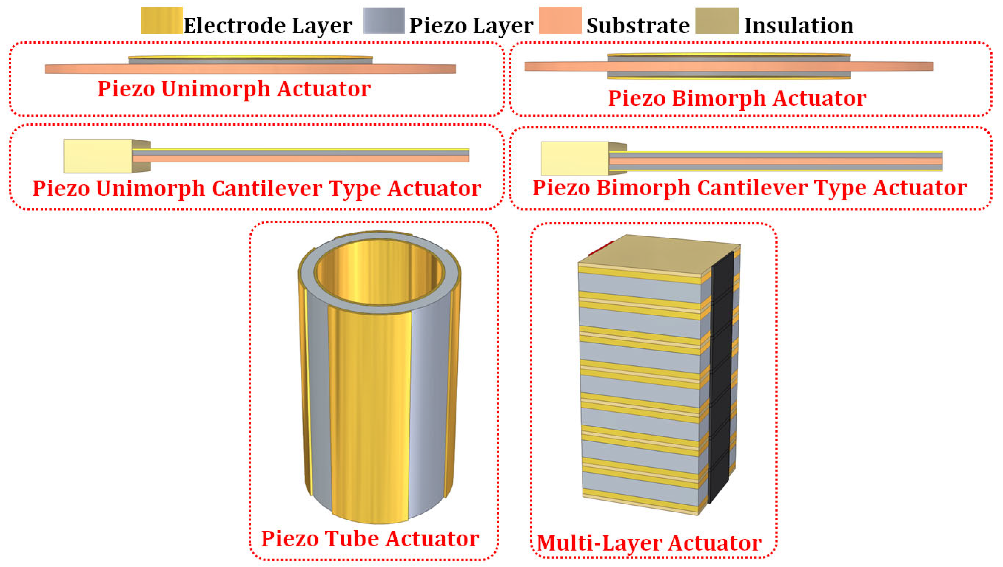
Figure 3.
Schematic representation of the nonlinearity in the piezoelectric actuators due to (a) hysteresis, (b) creep, and (c) Vibration.
Figure 3.
Schematic representation of the nonlinearity in the piezoelectric actuators due to (a) hysteresis, (b) creep, and (c) Vibration.
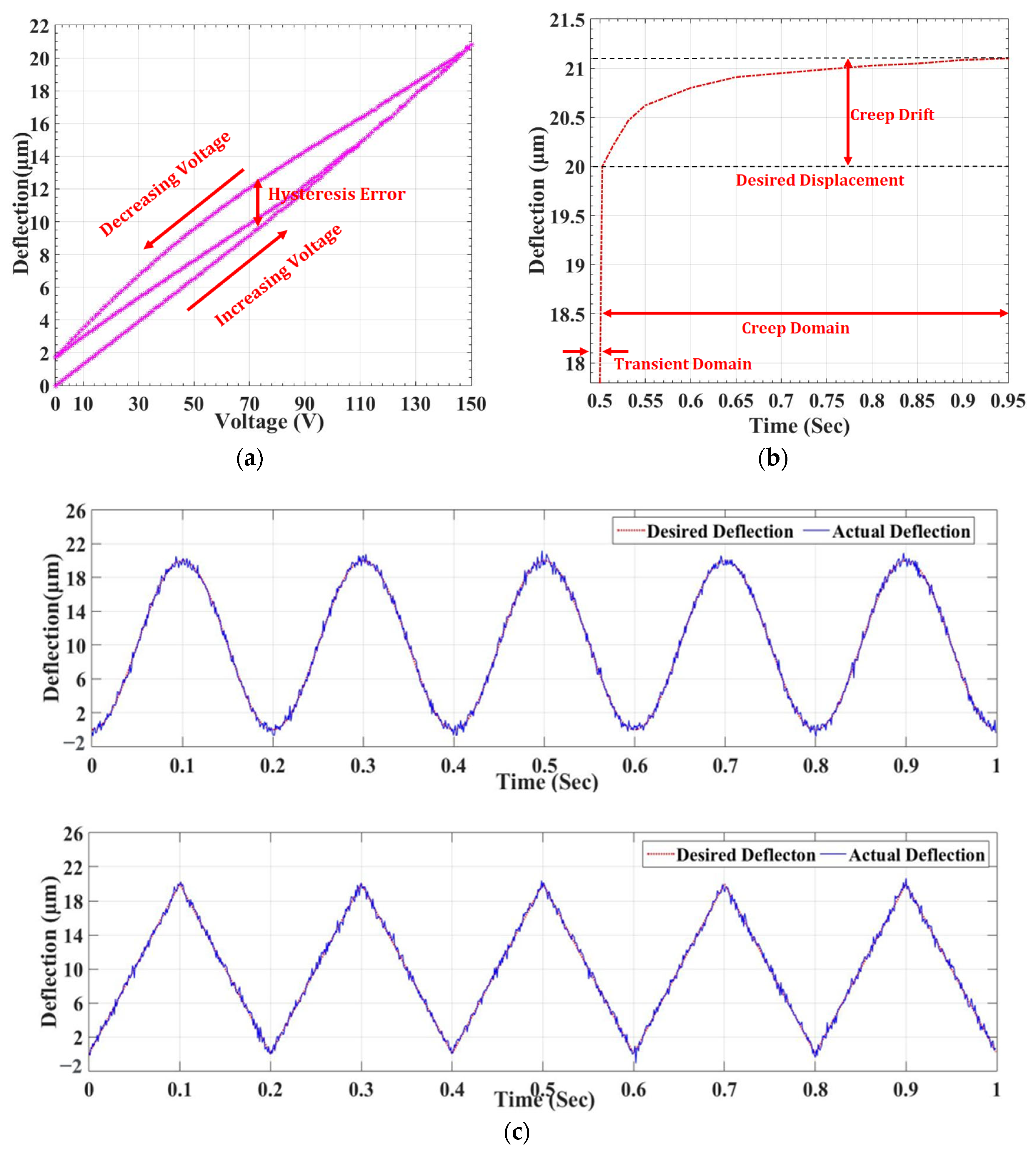
Figure 4.
Schematic representation of the electromechanical model of the piezoelectric actuator.
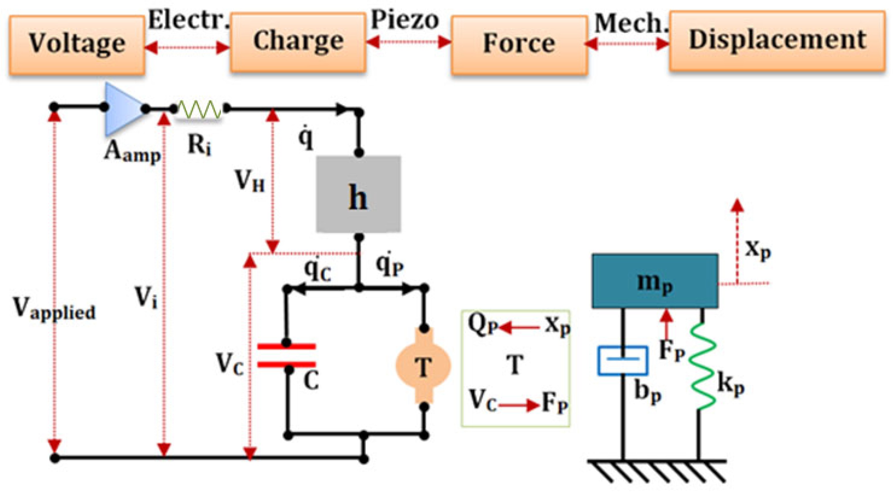
Figure 5.
Driving and control approaches for the piezoelectric actuators.
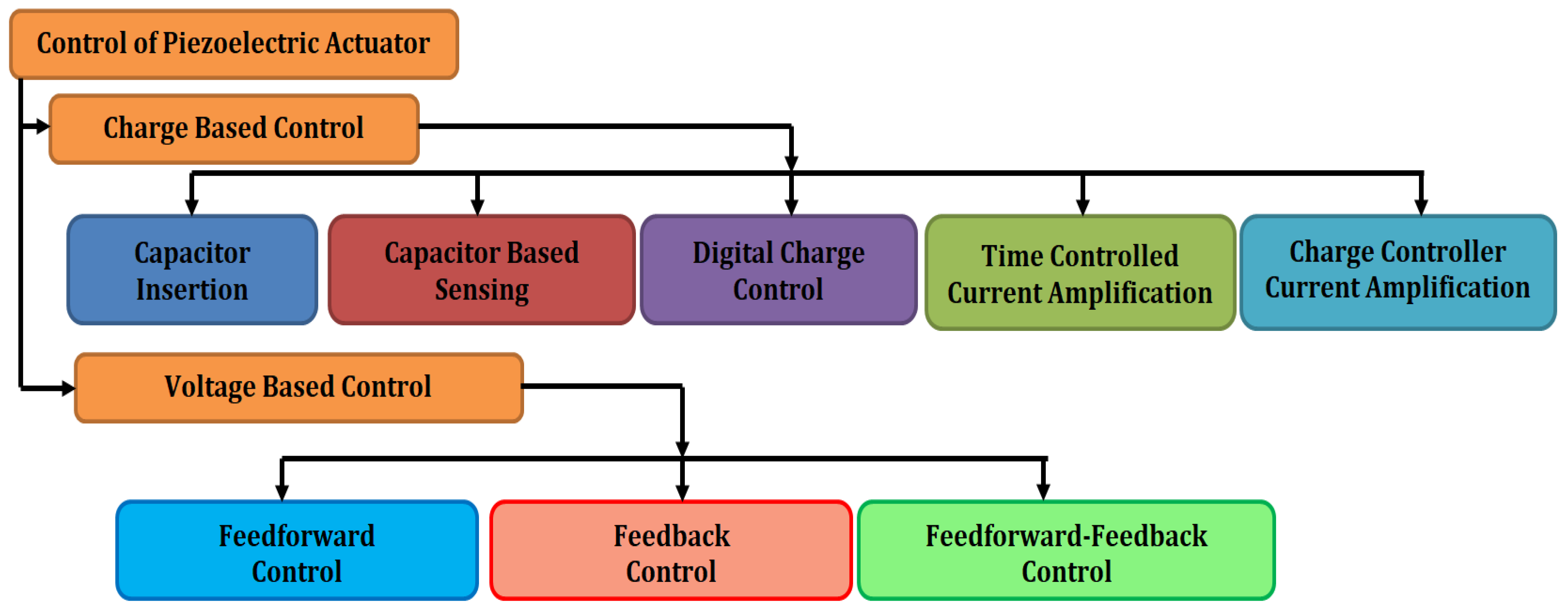
Figure 6.
Schematic of the charge-driven piezoelectric actuator with the capacitor insertion.
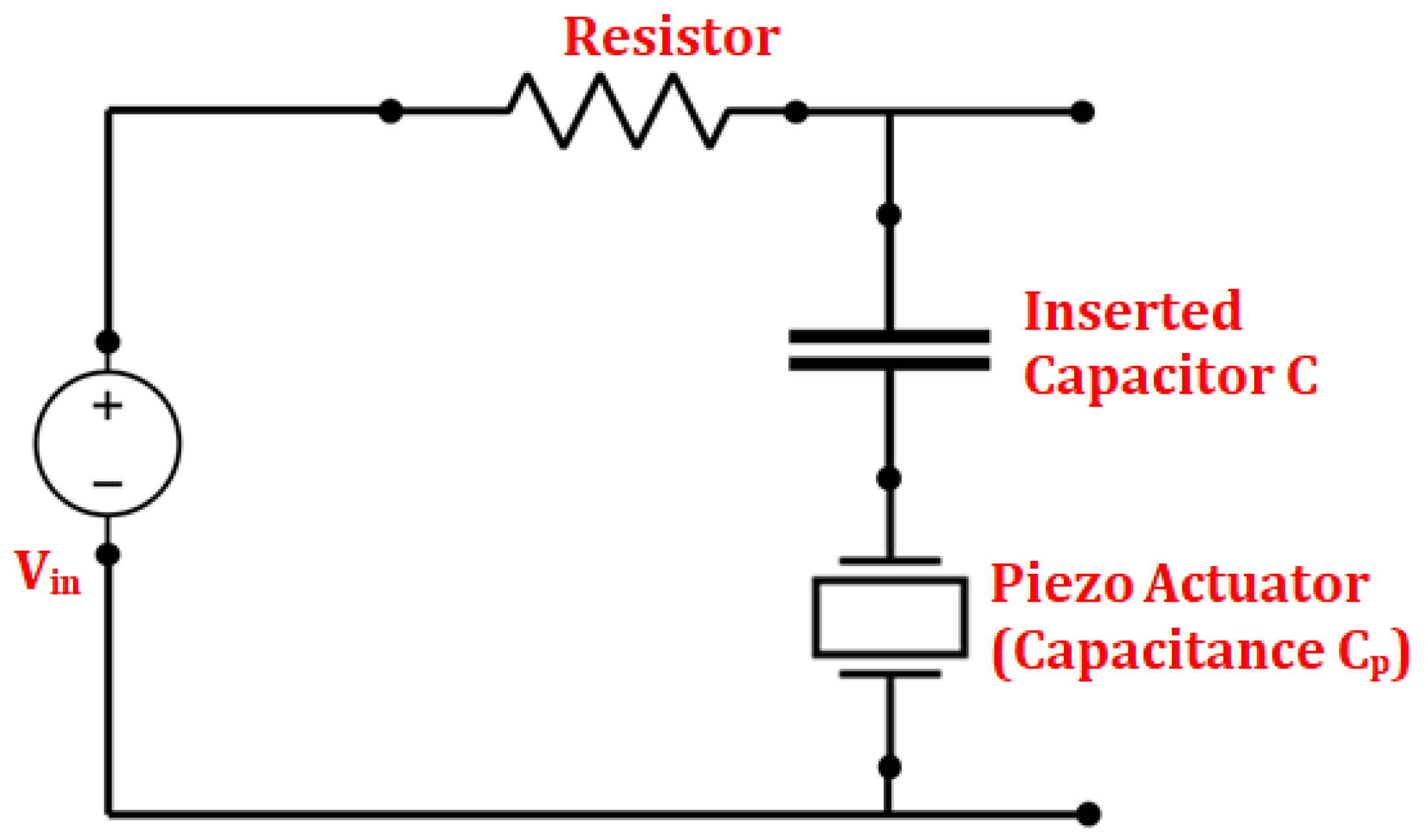
Figure 7.
Charge-driven piezoelectric actuator with time-controlled current amplification.
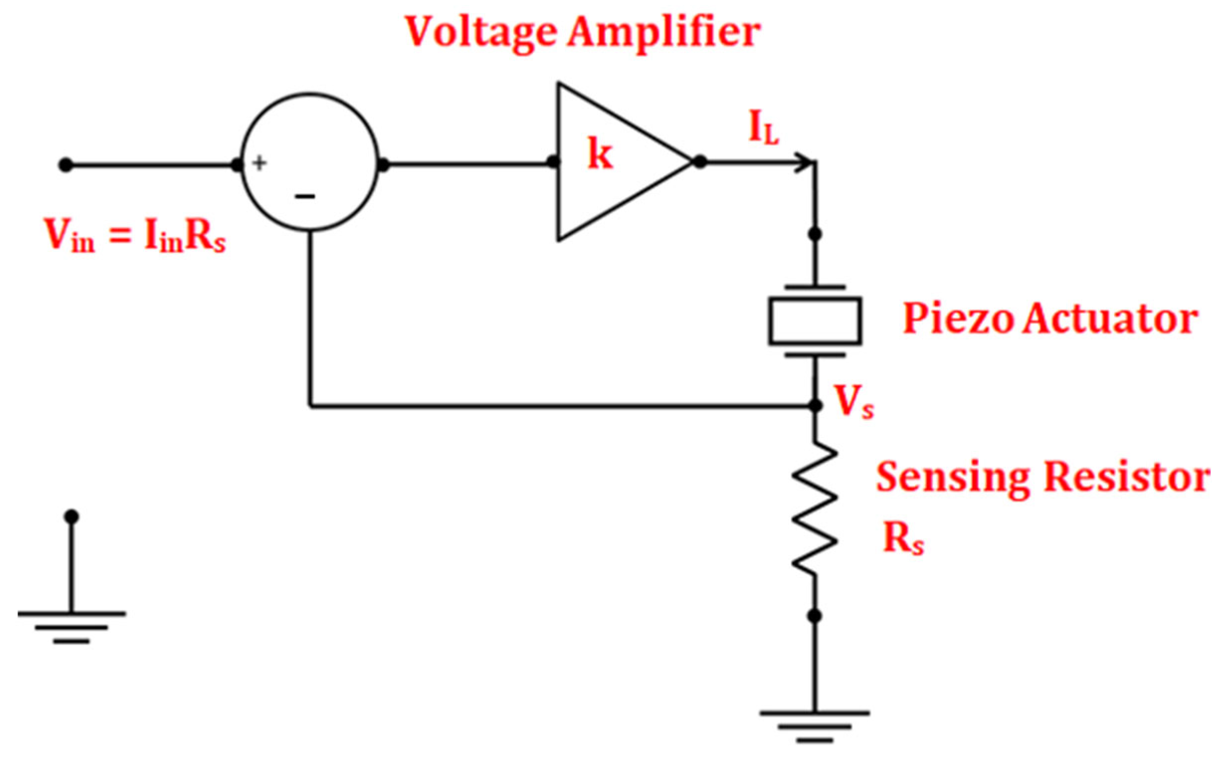
Figure 8.
Schematic of the charge-driven piezoelectric actuator with the capacitor-based sensing (a) Generic charge amplifier (b) Grounded load DC accurate charge amplifier.
Figure 8.
Schematic of the charge-driven piezoelectric actuator with the capacitor-based sensing (a) Generic charge amplifier (b) Grounded load DC accurate charge amplifier.
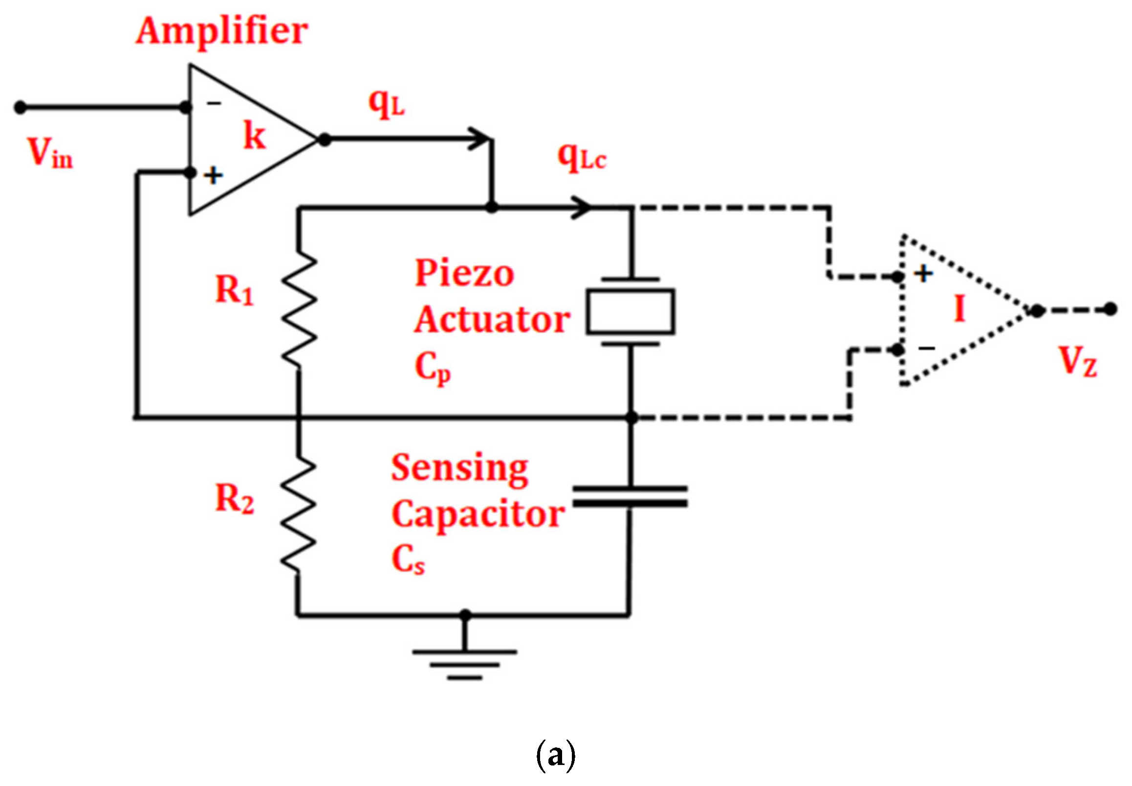
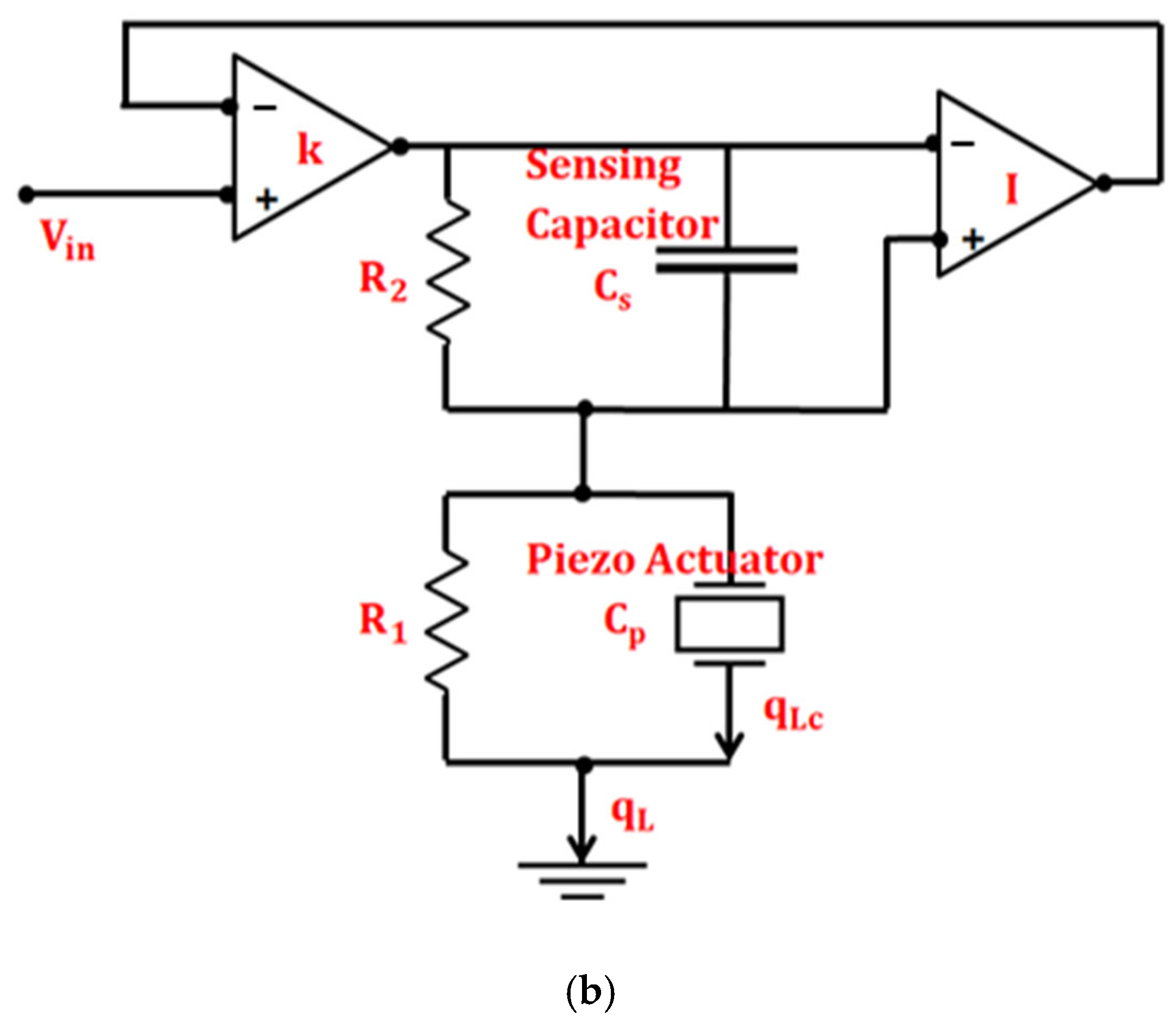
Figure 9.
Schematic of (a) linear charge controller without DC feedback, (b) linear charge controller with DC feedback, and (c) nonlinear charge controller.
Figure 9.
Schematic of (a) linear charge controller without DC feedback, (b) linear charge controller with DC feedback, and (c) nonlinear charge controller.
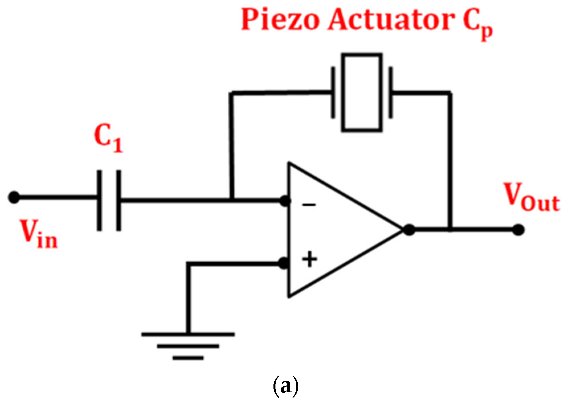

Figure 10.
Schematic of the charge-driven piezoelectric actuator with the digital charge control.

Figure 11.
Classification of hysteresis model of the piezoelectric actuators.
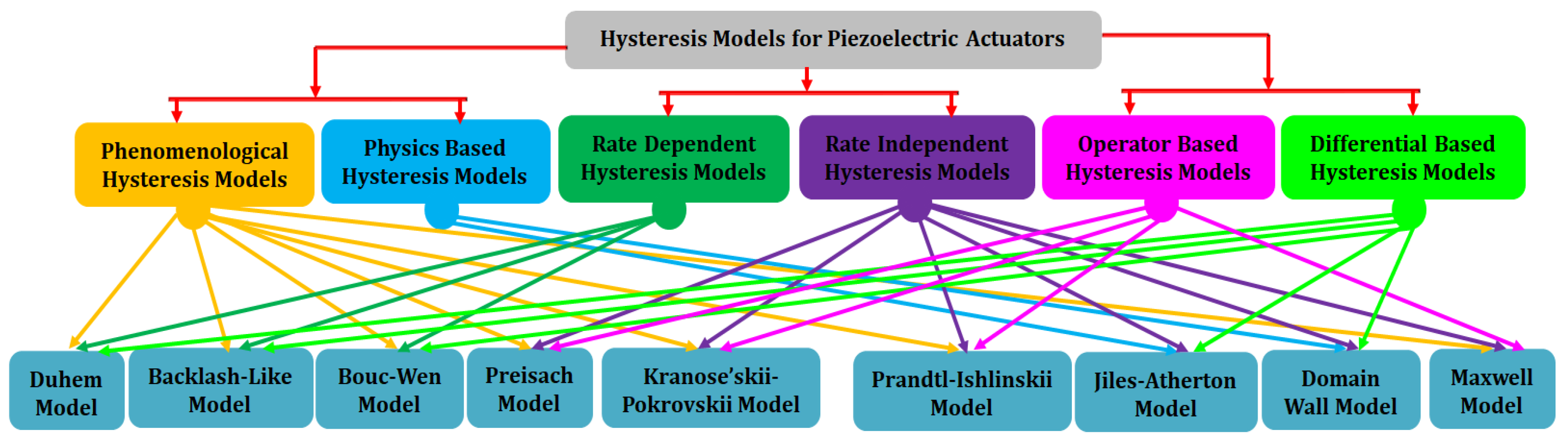
Figure 12.
Mapping of Hysteresis in the α-β plane for the Preisach model.
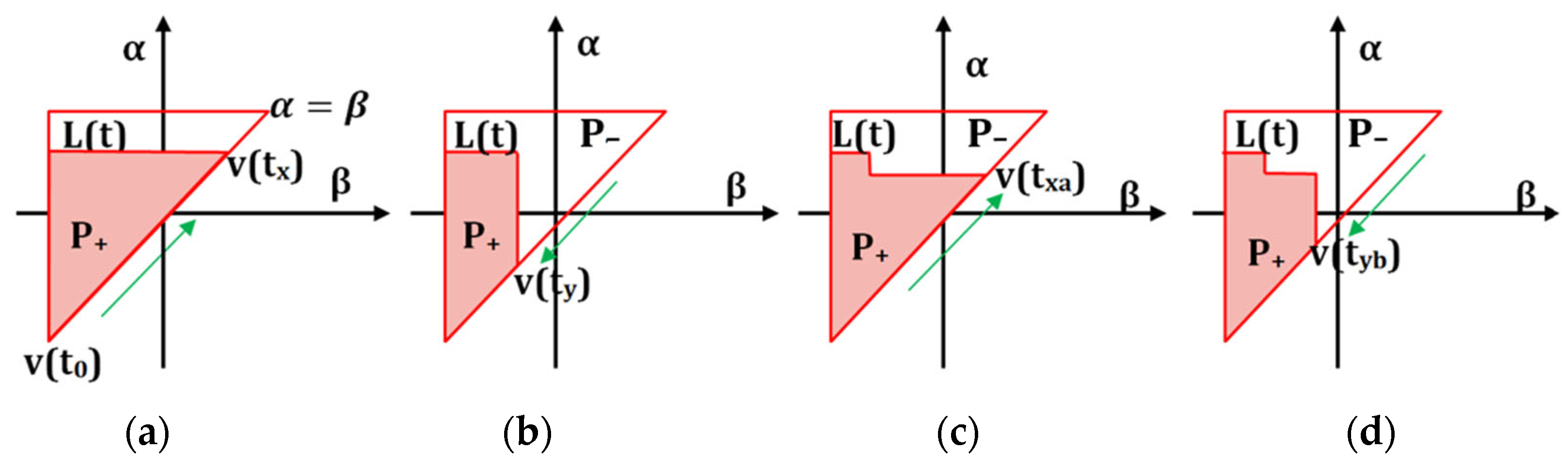
Figure 13.
Geometric representation of (a) Play Operator (b) Stop Operator.

Figure 14.
Schematic of the Krasnoselskii–Pokrovskii kernel.
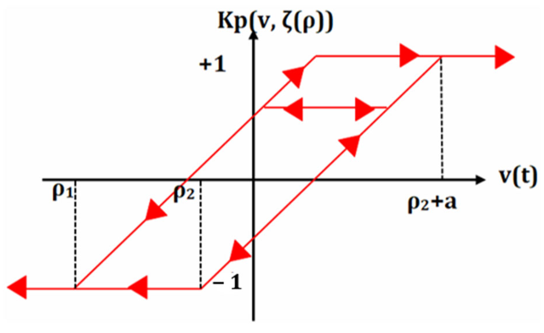
Figure 15.
Schematic representation of the Maxwell–Slip Hysteresis model.
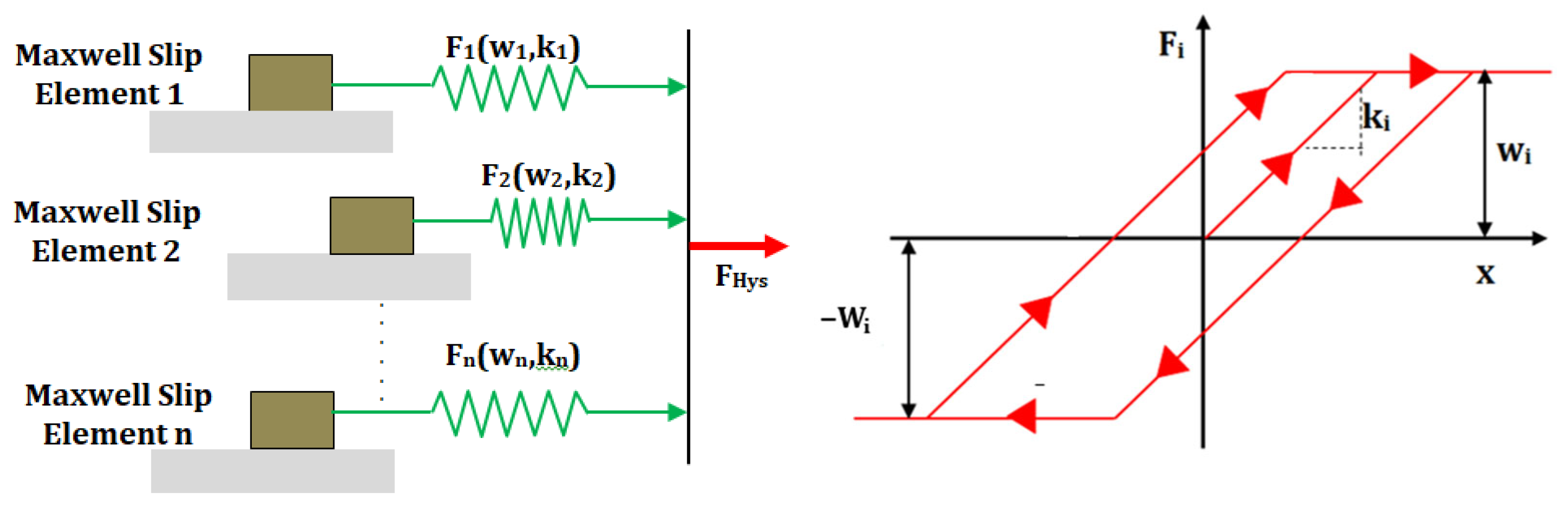
Figure 16.
Viscoelastic creep model of the piezoelectric actuators.
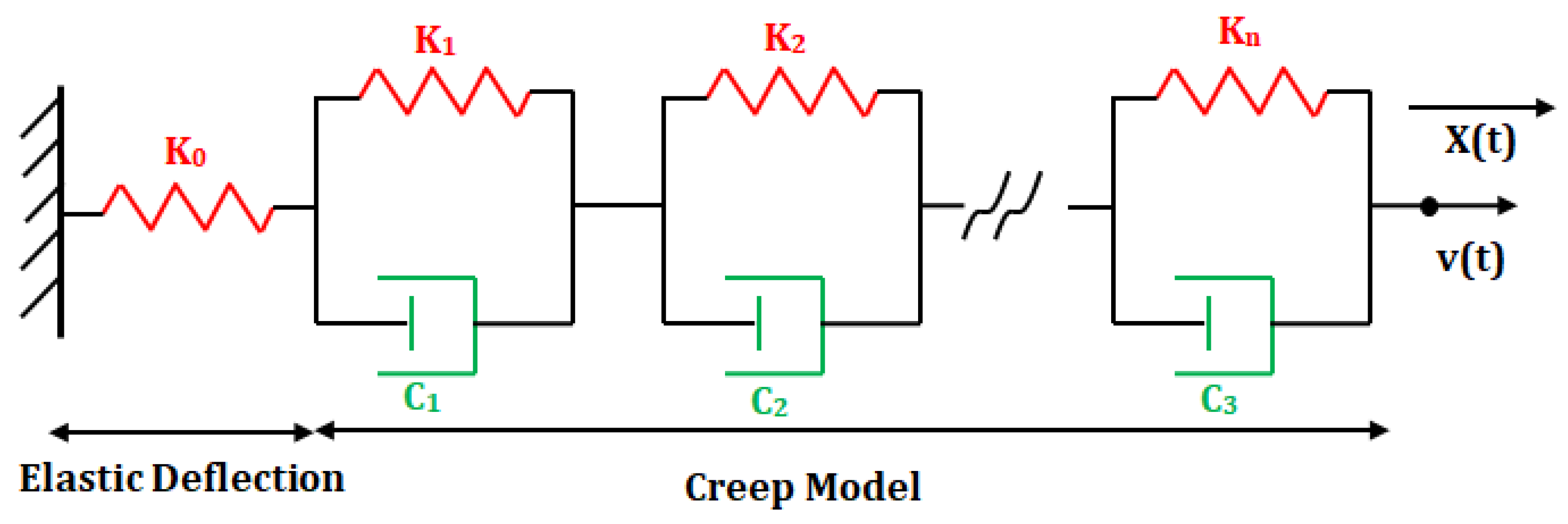
Figure 17.
Block diaphragm of the Feedforward control of the piezoelectric actuator.
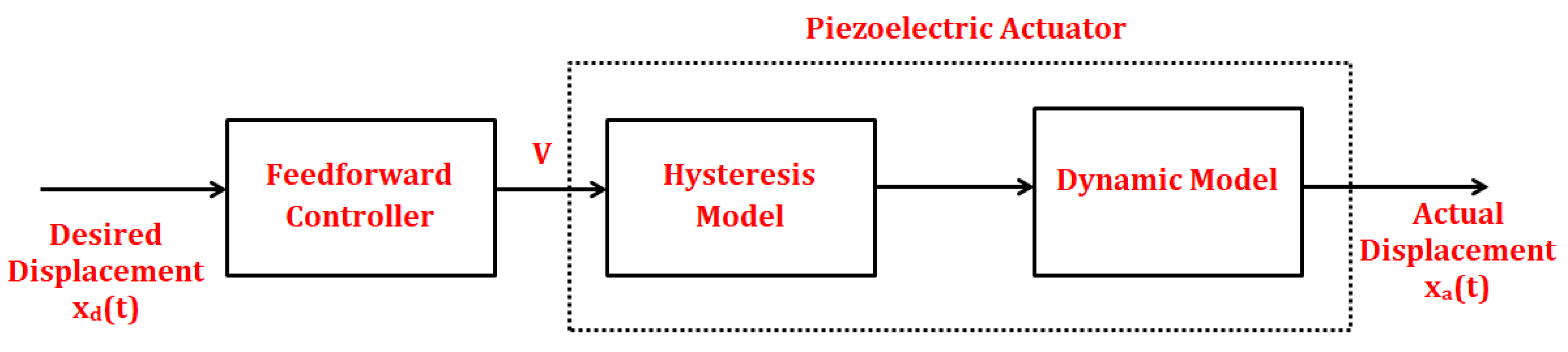
Figure 18.
Block diaphragm of the feedback control of the piezoelectric actuator.
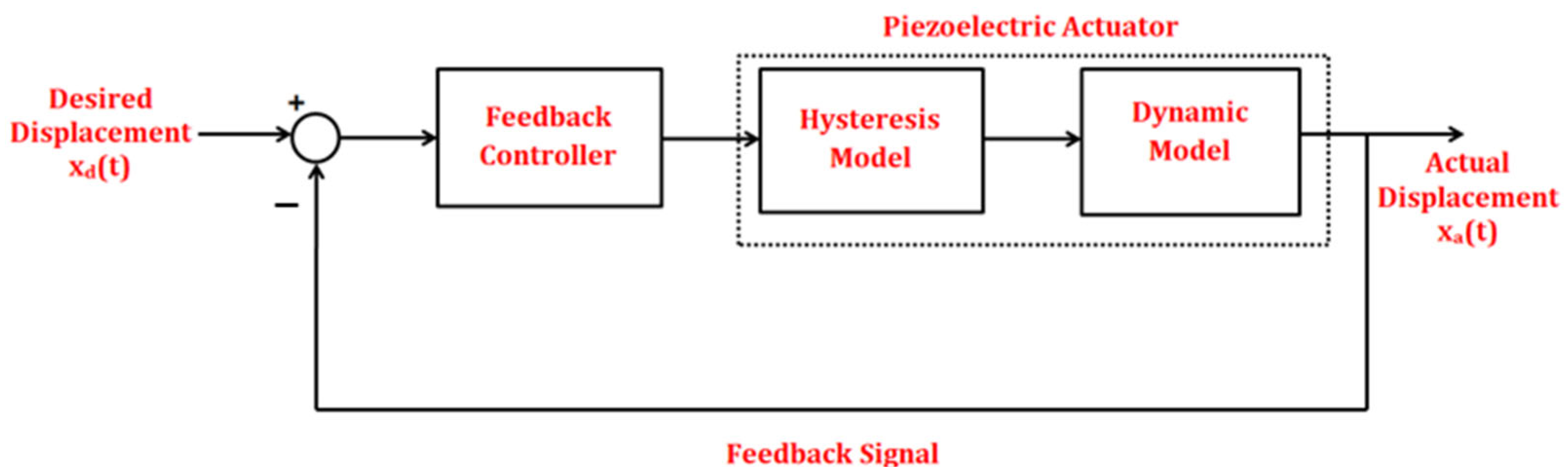
Figure 19.
General representation of the proportional integral derivative (PID) controller.
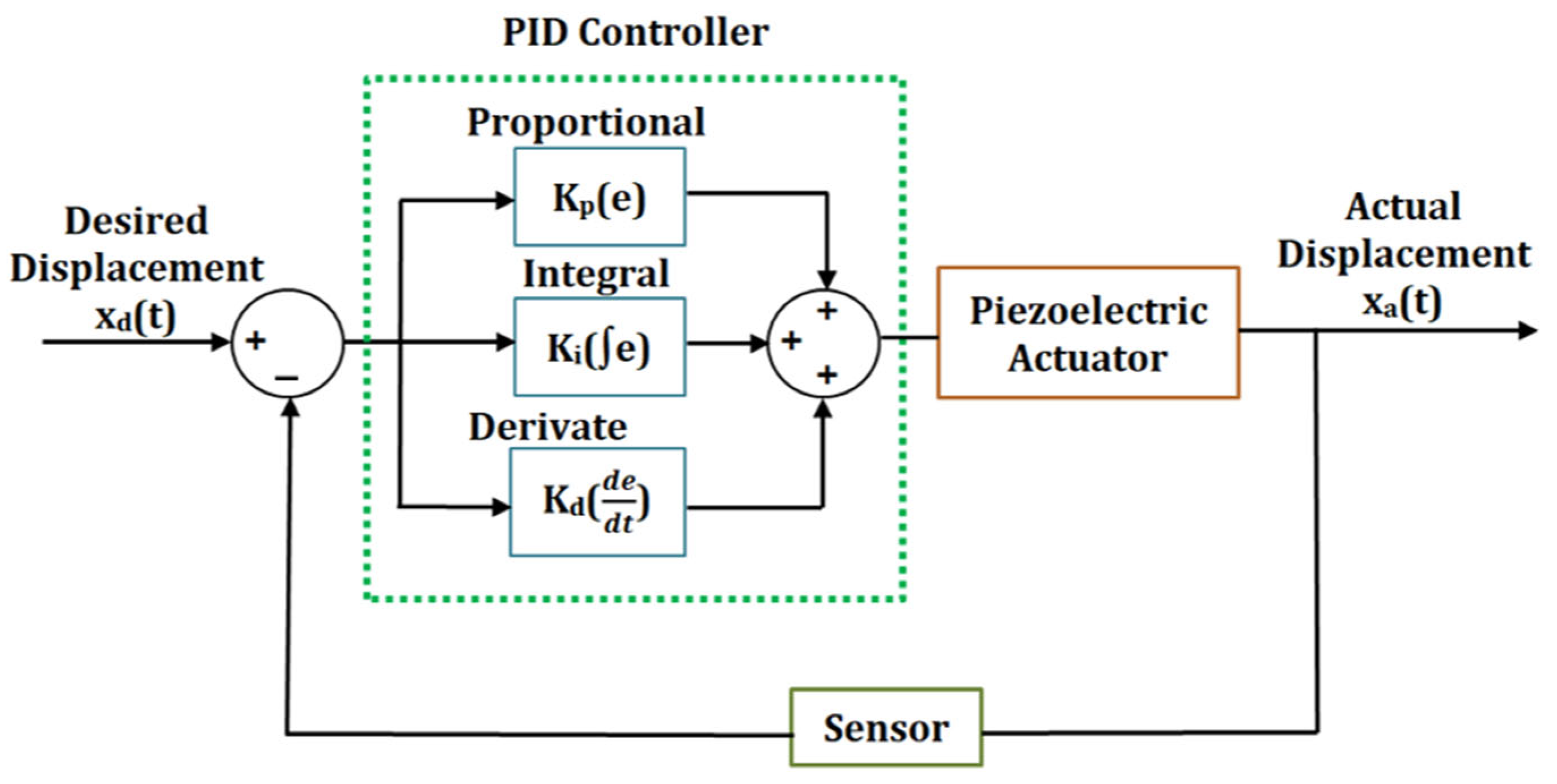
Figure 20.
Schematic of the self-tuning fuzzy PID controller.
Figure 21.
Schematic of the fractional order fuzzy PID controller.

Figure 22.
Schematic of the disturbance observer-based PID Controller.
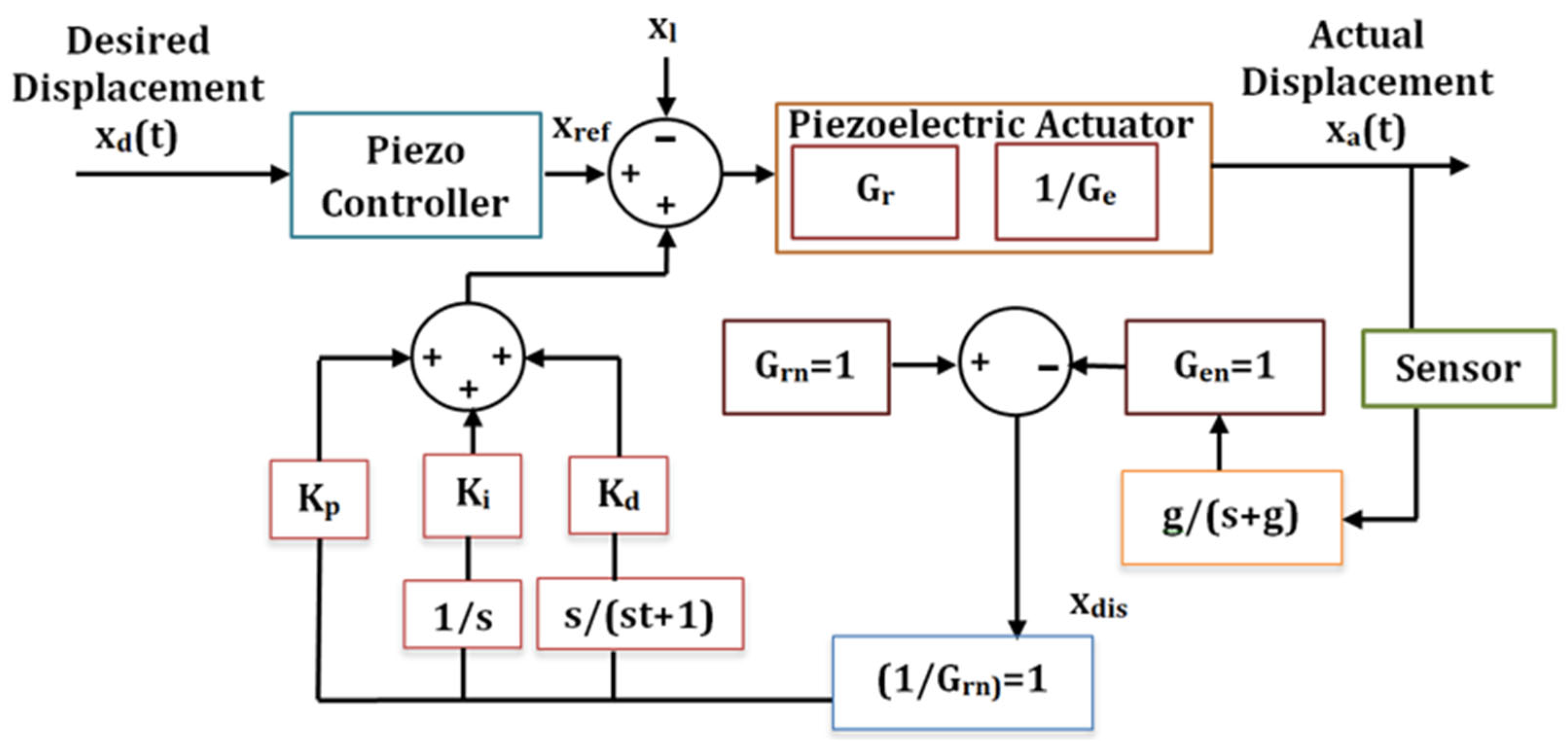
Figure 23.
(a) Schematic of the piezoelectric actuator as a generalized plant (b) Schematic of control of the piezoelectric actuator under closed loop H∞ control method with weighting filters.
Figure 23.
(a) Schematic of the piezoelectric actuator as a generalized plant (b) Schematic of control of the piezoelectric actuator under closed loop H∞ control method with weighting filters.
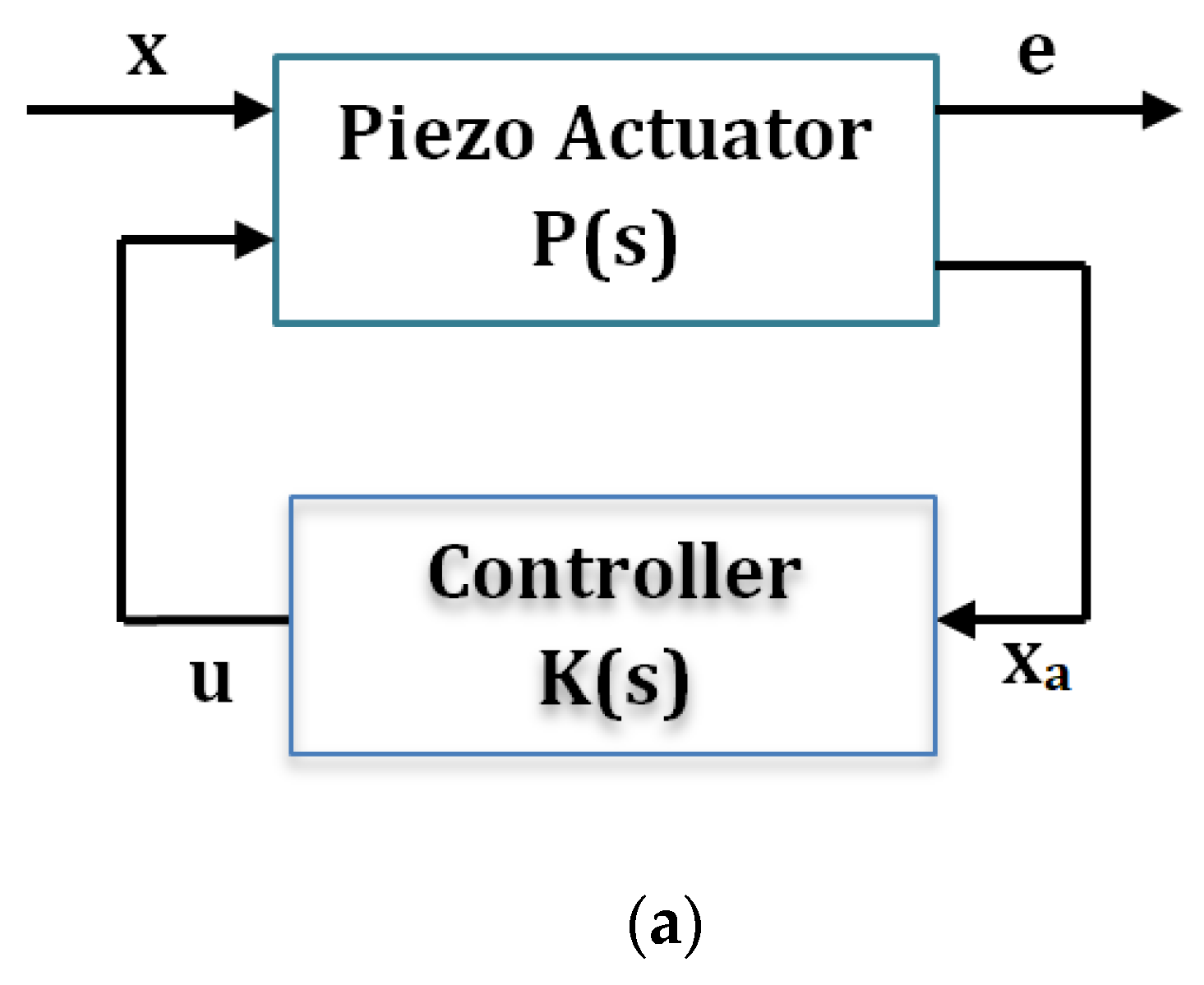
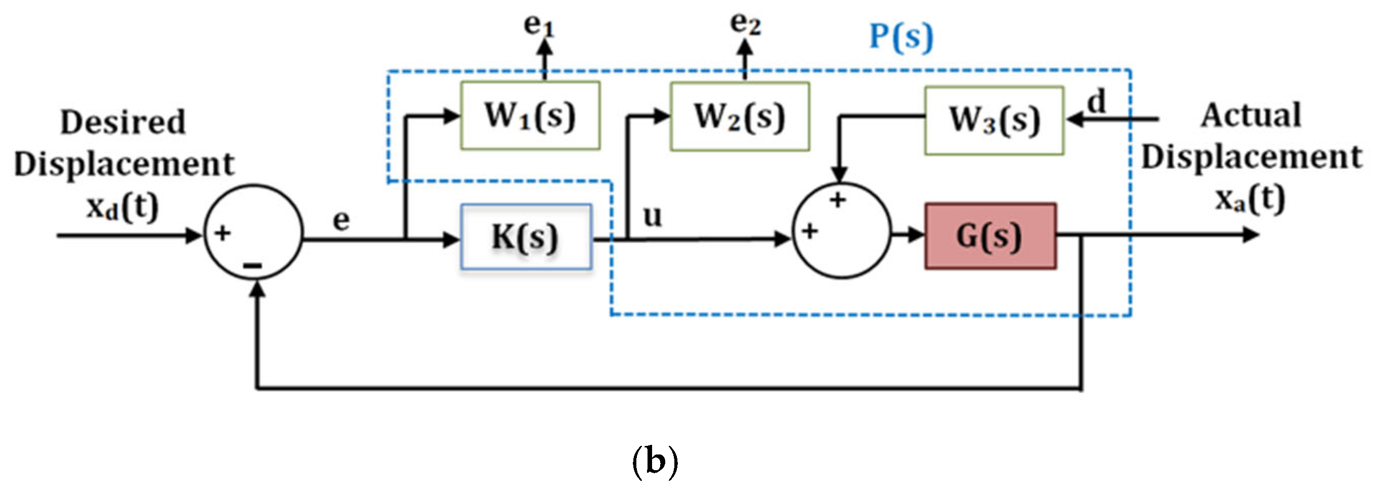
Figure 24.
Schematic representation of the sliding mode controller of the piezoelectric actuator.

Figure 25.
Block diaphragm of the feedforward–feedback control of the piezoelectric actuator.
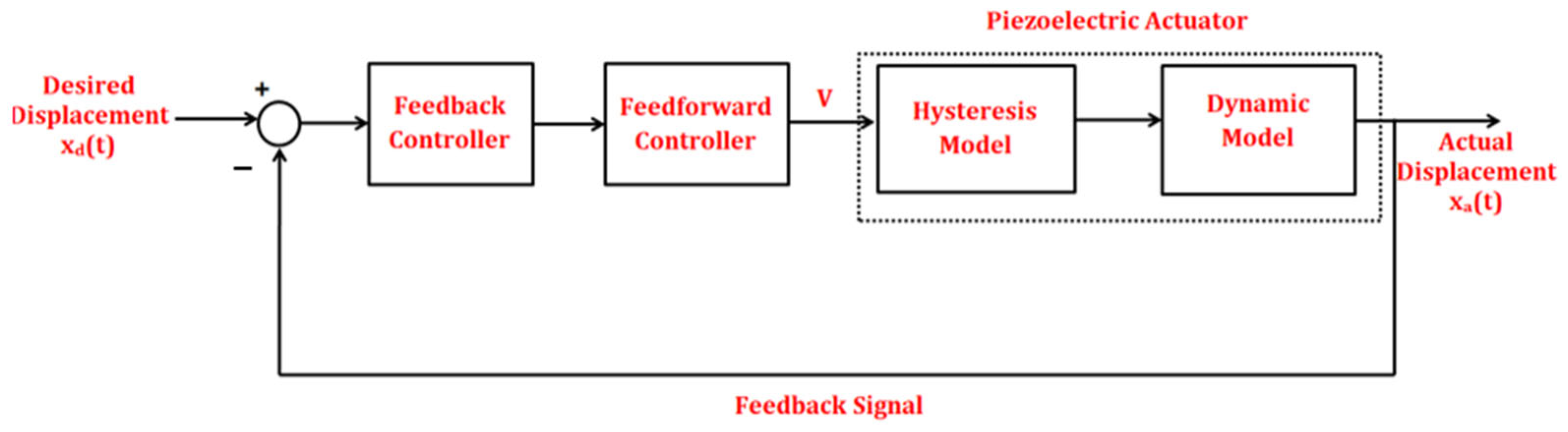
Table 1.
Application of charge-based control of the piezoelectric actuators reported in recent years.
Table 1.
Application of charge-based control of the piezoelectric actuators reported in recent years.
| Author | Year | Ref. No. | Type of Actuator | Method of Charge Control | Voltage (V) | Frequency (Hz) | Range of Motion (μm) | Approximate % Reduction in Hysteresis | Approximate % Reduction in Creep |
|---|---|---|---|---|---|---|---|---|---|
| J. Minase | 2010 | [68] | Piezo Stack | Capacitor Insertion | 100 | 10 | 2.25 | 99.59 | 99.87 |
| Y. T. Ma | 2011 | [69] | Piezo Stack | Capacitor Insertion | 5 | 5 | 5 | 94.36 | 77.00 |
| A. J. Fleming | 2005 | [73] | Piezo Tube | Capacitor based sensing | ±6 | 10 | ±3.00 | 89.00 | ---- |
| A. J. Fleming | 2010 | [74] | Piezo Stack | Capacitor based sensing | 150 | 100 | 7.8 | 95.35 | ---- |
| Shannon A. | 2015 | [75] | Bimorph | Capacitor based sensing | −50 to +200 | 15 | ±1250 | 92.00 | ---- |
| C. Yang | 2017 | [77] | Piezo Stack | Nonlinear Charge Controller | 100 | 2 | 6.50–7.00 | 88.00 | ---- |
| T. Jin | 2019 | [79] | Piezo Stack | Linear Charge Controller | 4.5 | 2 | 2.50–3.00 | 71.33 | ---- |
| T. Jin | 2019 | [79] | Piezo Stack | Nonlinear Charge Controller | 4.5 | 2 | 2.50–3.00 | 91.29 | ---- |
| M. Bazghaleh | 2014 | [81] | Piezo Stack | Digital Charge Amplification | 40 | 10 | 11.54 | 91.00 | ---- |
| J. Zhong | 2021 | [82] | Piezo Stack | Digital ChargeConrol | 120 | 1–1000 | ±2.00 | 99 | |
| Chen Yang | 2022 | [83] | Piezo Stack | Nonlinear Charge Controller | 50 | 10–400 | 3.3 | 97 |
Table 2.
Application of the hysteresis models in the piezo actuation technology reported upto the year 2020.
Table 2.
Application of the hysteresis models in the piezo actuation technology reported upto the year 2020.
| Author | Year | Ref. No. | Type of Actuator | Hysteresis Model | Observation |
|---|---|---|---|---|---|
| T. Hegewald | 2008 | [116] | Piezo Stack | Jiles–Atherton |
|
| L. Deng | 2008 | [117] | Piezo Positioning Stage | Backlash |
|
| M. Zhou | 2013 | [118] | Piezo Stack | Duhem |
|
| Y. Liu | 2013 | [119] | Piezo Positioning Stage | Maxwell–Slip |
|
| T.-G. Zsurzsan | 2015 | [120] | Piezo Motor | Preisach |
|
| J. Gan | 2016 | [121] | Preloaded Piezo Stack | Prandtl–Ishlinskii |
|
| G. Wang | 2017 | [122] | Amplified Piezo Stack | Duhem |
|
| Y. Qin | 2017 | [123] | Compliant Piezo Stage | Prandtl–Ishlinskii |
|
| J. Gan | 2018 | [124] | Compliant Piezo Stage | Bouc–Wen |
|
| Y. Luo | 2018 | [125] | Piezo Stack | Preisach |
|
| Z. Li | 2018 | [126] | Piezo Positioning Stage | Krasnoselskii–Pokrovskii |
|
| D. Gan | 2019 | [127] | Compliant Piezo Stage | Duhem |
|
| J. Gan | 2019 | [128] | Compliant Piezo Stage | Bouc–Wen |
|
| Y. Chen | 2019 | [129] | Piezo Stack | Preisach |
|
| Y. Li | 2019 | [130] | Piezo Stack | Prandtl–Ishlinskii |
|
| W. Pan | 2019 | [131] | Piezo Positioning Stage | Krasnoselskii–Pokrovskii |
|
| D. Liu | 2020 | [132] | Piezo Bimorph | Bouc–Wen |
|
| L. Liu | 2020 | [133] | Amplified Piezo Stack | Bouc–Wen |
|
Table 4.
Comparison of Hysteresis Models.
| Hysteresis Model | Jiles–Atherton | Domain Wall | Duhem | Bouc–Wen | Backlash Type | Preisach | Prandtl–Ishlinskii | Krasnoselskii–Pokrovskii | Maxwell–Slip |
|---|---|---|---|---|---|---|---|---|---|
| Parameter | |||||||||
| Inverse Model | Easy | Easy | Difficult | Easy | Easy | Difficult | Easy | Difficult | Difficult |
| Rate-Independent | Yes | Yes | No | No | No | Yes | Yes | Yes | Yes |
| Rate-Dependent | No | No | Yes | Yes | Yes | No | No | No | No |
| Parameter Identification | Easy | Easy | Difficult | Easy | Easy | Difficult | Easy | Easy | Easy |
Table 5.
Application of different control strategies in the piezoelectric actuator technology.
| Author | Year | Ref. No. | Control Method | Type of Actuator | Sensor Used in Control | Observation |
|---|---|---|---|---|---|---|
| W. T. Ang | 2007 | [164] | Feedforward | Piezo Stack | N/A |
|
| K. K. Leang | 2009 | [166] | Feedforward | Piezo Tube | N/A |
|
| G. Y. Gu | 2012 | [171] | Feedforward | Piezo Stack | N/A |
|
| D. Wang | 2015 | [173] | Feedforward | Piezo Tube | N/A |
|
| N. U. Rahman | 2012 | [187] | Feedback Classical PID | Piezo Cantilever | Piezo Strain Sensor |
|
| B. Ding | 2016 | [188] | Feedback Classical PID | Piezo Stack | Capacitive Sensor |
|
| S. Bing | 2008 | [191] | Feedback Self-Tuning Fuzzy PID | Piezo Positioning Stage | Laser Vibrometer |
|
| Dongjie Li | 2017 | [192] | Feedback Self-Tuning Fuzzy PID | Piezo Positioning Stage | - |
|
| I. R. Birs | 2017 | [196] | Feedback Fractional Order Fuzzy PID | Piezo Cantilever | Piezo Strain Sensor |
|
| J. Yi | 2009 | [197] | Feedback Disturbance Observer PID | Piezo Cantilever | Fiber Optic Sensor |
|
| N. Chuang | 2010 | [202] | Feedback H Infinity | Piezo Stack | Differential Probe |
|
| S. Xiao | 2014 | [203] | Feedback H Infinity | Piezo Stack | Capacitive Sensor |
|
| M. Brahim | 2018 | [206] | Feedback H Infinity | Rotary Piezo Motor | Torque Sensor |
|
| S. Huang | 2009 | [209] | Feedback Sliding Mode | Piezo Stack | LVDT |
|
| M. Wehr | 2019 | [210] | Feedforward Sliding Mode | Piezo Stack | N/A |
|
| Z. Yu | 2020 | [211] | Feedback Sliding Mode | Piezo Positioning Stage | Laser Sensor |
|
| H. Y. Chen | 2018 | [216] | Feedforward- Feedback | Piezo Stack | Load Cell |
|
| A. Saleem | 2019 | [218] | Feedforward- Feedback | Amplified Piezo Stack | Laser Sensor |
|
| I. Ahmad | 2016 | [222] | Feedforward- Feedback | Piezo Positioning Stage | N/A |
|
| C. Napole | 2021 | [225] | Feedforward With ANN | Piezo Stack | N/A |
|
| S. Yu | 2021 | [226] | Feedback Sliding-Mode Control | Piezo Positioning Platform | - |
|
| D. Li | 2021 | [227] | Feedback Fuzzy Controller | Piezo Stack | Laser Sensor |
|
| S. Yu | 2022 | [228] | Feedforward Control With Composite Proportional–Integral Sliding Mode Control | Piezo Stack | Laser Sensor |
|
| B. Shi | 2022 | [229] | Feedforward /Feedback | Amplified Piezo Stack | Capacitive Sensor |
|
| Y. Xiong | 2022 | [230] | Feedforward Control | Piezo Positioning Platform | N/A |
|
| L. Cheng | 2023 | [231] | Feedback Sliding Mode | Piezo Stack | Strain Gauge Sensor |
|
| C. Napole | 2023 | [232] | Feedforward /Feedback With Fuzzy Logic | Piezo Stack | Wheatstone Bridge |
|
Disclaimer/Publisher’s Note: The statements, opinions and data contained in all publications are solely those of the individual author(s) and contributor(s) and not of MDPI and/or the editor(s). MDPI and/or the editor(s) disclaim responsibility for any injury to people or property resulting from any ideas, methods, instructions or products referred to in the content. |
© 2023 by the authors. Licensee MDPI, Basel, Switzerland. This article is an open access article distributed under the terms and conditions of the Creative Commons Attribution (CC BY) license (https://creativecommons.org/licenses/by/4.0/).
Share and Cite
MDPI and ACS Style
Kanchan, M.; Santhya, M.; Bhat, R.; Naik, N. Application of Modeling and Control Approaches of Piezoelectric Actuators: A Review. Technologies 2023, 11, 155. https://doi.org/10.3390/technologies11060155
AMA Style
Kanchan M, Santhya M, Bhat R, Naik N. Application of Modeling and Control Approaches of Piezoelectric Actuators: A Review. Technologies. 2023; 11(6):155. https://doi.org/10.3390/technologies11060155
Chicago/Turabian StyleKanchan, Mithun, Mohith Santhya, Ritesh Bhat, and Nithesh Naik. 2023. "Application of Modeling and Control Approaches of Piezoelectric Actuators: A Review" Technologies 11, no. 6: 155. https://doi.org/10.3390/technologies11060155
Note that from the first issue of 2016, this journal uses article numbers instead of page numbers. See further details here.