


Application of G.hn Broadband Powerline Communication for Industrial Control Using COTS Components

1
ZHAW Zurich University of Applied Sciences, School of Engineering, Institute of Embedded Systems, 8401 Winterthur, Switzerland
2
HSLU Lucerne University of Applied Sciences and Arts, Lucerne School of Engineering and Architecture, Institute of Electrical Engineering, Competence Center Intelligent Networks and Sensors, 6048 Horw, Switzerland
*
Author to whom correspondence should be addressed.
Technologies 2023, 11(6), 160; https://doi.org/10.3390/technologies11060160
Submission received: 10 October 2023
/
Revised: 26 October 2023
/
Accepted: 3 November 2023
/
Published: 10 November 2023
(This article belongs to the Topic Electronic Communications, IOT and Big Data)
Abstract
:Broadband powerline communication is a technology developed mainly with consumer applications and bulk data transmission in mind. Typical use cases include file download, streaming, or last-mile internet access for residential buildings. Applications gaining momentum are smart metering and grid automation, where response time requirements are relatively moderate compared to industrial (real-time) control. This work investigates to which extent G.hn technology, with existing, commercial off-the-shelf components, can be used for real-time control applications. Maximum packet rate and latency statistics are investigated for different G.hn profiles and MAC algorithms. An elevator control system serves as an example application to define the latency and throughput requirements. The results show that G.hn is a feasible technology candidate for industrial IoT-type applications if certain boundary conditions can be ensured.
1. Introduction
The transfer of technologies developed and matured for mass markets to other, more specialized areas of application has proven successful in many technical fields. Transfer of technologies developed for and matured in high-volume markets to other, more specialized application areas haves been demonstrated successfully in many technical areas. An industrial control example includes the real-time Ethernet (RTE) technologies specified by the International Electrotechnical Commission (IEC) in the IEC 61784-2 series standards. One main driver for such developments is expected savings due to economies of scale in technology and product development, maintenance, and costs of goods sold (COGS).
Broadband PLC (BPLC) technology has recently matured, facilitating the transmission of hundreds of megabits per second on the application layer for home networking and smart grid applications. The technology boasts various attractive attributes for other application areas, such as real-time control. Both ITU-T and IEEE published standards with comparable gross data rates: G.hn is specified in a series of ITU-T recommendations, and IEEE1901 is the standard specified by IEEE. A comprehensive comparison between the two has been provided previously [1]. G.hn [2,3,4,5], promoted by the home grid forum “https://homegridforum.org/” (accessed on 4 November 2023), distinguishes itself by its support for various media types—powerline, coaxial and twisted pair cables, and passive optical fiber (POF).
Research in the Internet of Things (IoT) identifies the reliability of components and communication systems as an area with significant potential for improvement [6,7]. In this context, powerline communication is a promising technology to increase the reliability and safety of IoT systems. This is particularly important for Industrial IoT (IIoT) systems, where safe and reliable operation often depends on timely message delivery. The time-sensitive networking (TSN) activities of IEEE [8] address the requirements for high-end motion control applications, which is outside the scope of our investigation. Powerline communication (PLC) does not suffer from certain inherent weaknesses of wireless communication, such as attenuation due to penetration of walls and other obstacles or—relevant to our selected application—reflections in an elevator shaft with metallic material. Compared to traditional wire-based communication systems, BPLC has advantages in cabling costs and also does not require well-structured cabling with terminating resistors and limited stubs to prevent reflections. Hence, BPLC is designed to cope with unstructured cabling.
Contributions of This Paper
This work investigates to which extent G.hn technology, using existing commercial off-the-shelf (COTS) components available in the market, can be used for real-time control applications. The focus is on achievable packet rates and worst-case latencies caused by the behavior of G.hn’s medium access algorithms. Although we do not focus on time-variant frequency selective fading or possibly required filters for network segmentation, where relevant, these topics are briefly discussed.
We identified the packet rate as a limiting factor in BPLC systems and derived maximum values from analyzing the G.hn specifications. This is important as IIoT applications typically rely on cyclic transmission of short packets with time-critical data. Through an extensive measurement campaign with available COTS components and their functionality, we identified the achievable latency and packet throughput. We presented it in a way that facilitates the assessment of suitability and outlier distribution.
A typical elevator control system serves as an example for an IIoT application to define the latency and throughput requirements. A potential architecture is presented, and the suitability of G.hn to meet latency and throughput is assessed based on our measurements. We found that advanced optional features may not be implemented in COTS components, and measurements are necessary. In particular, direct contact with the vendors is of tremendous value.
Additionally, requirements and recommendations for application programming to compensate for the limitations of G.hn communication are presented, and topics for further research are identified.
The work is structured as follows: Section 2 reviews work related to the performance of BPLC systems and the application of the same for IIoT use cases. Section 3 presents a short overview of G.hn, focusing on the PHY and MAC properties relevant to latency and throughput, our findings regarding COTS components, and the methods used for our analysis. The elevator control system and its requirements for the communication system are presented in Section 4, while measurement results are presented in Section 5. Section 6 discusses the results of our investigation and proposes an architecture that will satisfy the requirements. Section 7 elaborates on where the real conditions may deviate from those in the lab; the final Section 8 provides our conclusions.
2. Related Work and Research Questions
Approximately one decade ago, Dominiak et al. [9] performed a detailed investigation of the applicability of commercial BPLC in avionics (cabin lighting and communication system) using a predecessor technology of G.hn. They concluded that, while the commercial system offers sufficient throughput, the implemented MAC scheduling algorithms are optimized for internet access and do not achieve the required performance for targeted avionics applications.
Since then, BPLC has evolved to allow data rates one order of magnitude above those discussed by Dominiak et al. [9]. Silicon from different vendors is available, and the consumer market has adopted BPLC technology to extend home networks beyond a single wireless access point.
An extensive survey of MAC protocols for PLC has been provided previously [10], in which MAC algorithms were analyzed and classified according to their algorithmic properties. They provided perspectives for their main application area in a complementary analysis in the same paper. The paper proposes three categories: smart things (grids, meters, and homes), multimedia, and in-vehicle (automotive or aerospace) applications. Their survey focused on principles of operation and relevant properties of different MAC algorithms, thus it did not provide quantitative data.
An in-depth analysis of the achievable PHY data rate for the SISO powerline profile of G.hn has also been presented previously [11]. The authors base their results on a detailed analysis of the G.hn PHY and MAC properties regarding symbol duration, forward error correction (FEC) rate, and block size, among other parameters. They focus on PHY parameters; MAC layer scheduling is not considered in the calculations or simulations. They demonstrate that data rates up to approximately 250 Mbit/s can be achieved under good conditions, including excellent channel quality and a sufficiently high modulation order between G.hn nodes. This ensures that the payload of G.hn packets is sufficiently large to fill the FEC blocks and OFDM symbols of a G.hn packet. The nominal PHY data rates in the order of 1.5–4 Gbit per second listed in Table 1 and in Section 3.1.1 are theoretical values multiplying all best-case parameters that real installations will not reach.
Pereira et al. [12] investigated the industrial application of IEEE 1901.2. The targeted application requires support of up to 6 km physical distance, different phases, intermediate transformers, electrical machines, and inverters directly connected to the power lines. They focused on channel characteristics and concluded that the upper-frequency range of IEEE 1901.2 in the FCC range between 145 and 478 kHz was best suited. The metrics used for success included a simple packet loss rate measured for different modulation modes. Latencies, throughput, and medium access were not addressed, and latency values for the applications were reported as 1–2 s.
Another example was provided by Bucci et al. [13], in which a PLC system was presented for a clinical IoT application, collecting data from oximeters. The associated hardware is commercially available and used for streetlight applications. For applications requiring relatively low cyclic reading (numbers are not given), a round-robin master–slave protocol with a packet size of 3 bytes was proposed. The systems presented in [12,13] neither employ BPLC nor use the currently available advanced, integrated solutions.
Rahman et al. presented and compared the MAC algorithms of IEEE 1901 and G.hn in detail [1]. As the work was performed in parallel with the standardization efforts, it was purely based on the specifications without distinguishing between mandatory and optional features implemented in commercial products.
A technical report from ITU-T [14], published in 2020, describes use cases for industrial applications, including building entrance guard systems, smart lifting, smart traffic lights, navigation lighting aid in airports, and charging stations. However, the description of the use cases is relatively short and high-level. For example, the use case for “smart lifting” is restricted to video transmission to and from the elevator car, similar to a home networking scenario and the multimedia use case described by De Oliveira et al. [10]. Elevator control as such is not mentioned.
A recent blog post on LinkedIn [15] provides a simplified recommendation for applying G.hn in elevator control.
None of the studies described above deal in-depth with the application of BPLC in industrial control applications where latencies in the order of 10–50 milliseconds are required. Hence, the current work closes this gap.
Goal of the Presented Research
To close some of the identified gaps in the related work, we aim to assess the achievable latencies and packet throughput of BPLC for IIoT control applications. The research questions driving this work are as follows:
Q1:
Are today’s COTS BPLC components suitable for IIoT applications? Which worst case latencies can be expected?
We define “IIoT application” as a medium-range application in the industrial automation context. Hence, we do not target high-end robotics, motion, or high-voltage switchgear control, where engineered networks such as EtherCAT, PROFINET IRT, POWERLINK, IEC61850, or Sercos III [16] are used in a dedicated and well-controlled environment. Also, we exclude large-scale process control installations with hundreds or thousands of nodes. The need for IP connectivity to all nodes was assumed to support advanced monitoring functions and unified access to the nodes in the system.
Q2:
How can system and application design facilitate the use of BPLC for IIoT?
Given the assumption that specific properties of BPLC will differ from traditional communication technology for IIoT, what should be observed at the application level to mitigate these? Which means are required to provide the required robustness against late message delivery?
3. Materials and Methods
3.1. G.hn Technology
G.hn is a communication technology on OSI layers 1 and 2 (physical and data link layers). A typical application is the extension of a home network: a pair of G.hn modems that the user plugs into two different AC power sockets in the home and connects devices to the Ethernet interfaces of the modems or uses one as a wireless access point. In this scenario, G.hn transparently transports Ethernet frames using the existing AC power lines for the end devices. In addition to powerlines, G.hn also specifies profiles that can use existing telephone lines, coax cables, or passive optical plastic fiber (POF).
G.hn is standardized in a series of recommendations published by ITU-T, the Telecommunication Standardization Sector of the International Telecommunication Union (ITU). The core specifications are G.9960–G.9964 [2,3,4,5,17], which describe the architecture, physical and data link layers, management, and spectral emission requirements. Additional specifications define coexistence, security, and extended management, which are regularly updated and amended. An overview of all G.hn standards and the technology has been provided previously by ITU-T [18].
3.1.1. Physical Layer
G.hn supports 3 physical layers for electrical media: powerline, telephone line (twisted pair), and coax cabling; the main properties of each are presented in Table 1.

Table 1.
G.hn profile overview (for electrical media).
| Property | Powerline | Telephone Line | Coax |
|---|---|---|---|
| Modulation | OFDM | ||
| Modulation order | BPSK to 4096-QAM (1 to 12 Bit/symbol, variable per subcarrier) | ||
| Spectrum (used) | 2–100 MHz (2–80 MHz) | 2–200 MHz | 5–200 MHz |
| Subcarrier spacing | 24.4 kHz | 48.8 kHz | 195.3 kHz |
| MIMO support | Yes | Yes (for bonded lines) | No |
| Forward error correction (FEC) | LDPC, rate 1/2, 2/3, 5/6, 16/18, 20/21 | ||
| Encryption | AES-256 | ||
| Theoretical max data rate (PHY/MAC) | 1500/1000 Mbit/s | 4000/3400 Mbit/s | 2000/1700 Mbit/s |
| Automatic repeat request (ARQ) | Yes | ||
| Medium Access | TDMA; coordinated by a domain master (DM) | ||
| QoS (in end nodes) | 8 levels | ||
The telephone line profile is optimized for last-hop access and in-home networks with point-to-point or point-to-multipoint communication over a single phone line [19]. In the current study, we focus on the powerline profile and consider the telephone profile for situations with a distinct point-to-point link.
The physical layer of the powerline profile uses OFDM with 4096 subcarriers in the frequency range of 0 to 100 MHz, of which only 70% can be used due to regional regulations that prohibit the use of certain subchannels between 0 and 54 MHz, and the complete range > 80 MHz. Each subcarrier is modified with a modulation index between 1 and 12 bits per symbol (BPSK up to 4096-QAM), depending on attenuation and noise level. This bit allocation can differ per subcarrier and between any two nodes in the G.hn powerline network. Specific, highly robust default bit allocations are predefined in the G.hn recommendations. To optimize performance, channel estimation between two nodes is used to identify suitable bit allocations per subcarrier and required forward error correction (FEC) rates.
The symbol duration is 40.96 µs, with an inter-symbol gap of 10.24 µs. A thorough analysis of the theoretical maximum throughput based on the G.hn recommendations and simulations was provided by Mudriievskyi and Lehnert [11]. For the industrial control use case, where short packets containing sensor/actor or supervision data are exchanged, the data rate is not the relevant performance metric. Instead, the critical factor is the maximum number of packets that can be transmitted over the shared channel. G.hn uses FEC block sizes of 120 and 540 bytes, which are sufficient for short Ethernet/IP/UDP packets. Typically, an application message can be transmitted in a packet with a single FEC block in a control application.
For the home automation scenario, differential transmission between the phase and the neutral and protective Earth wiring can be exploited to implement 2 × 2 MIMO.
3.1.2. Medium Access
One of the nodes in the G.hn network operates as the domain master (DM) and controls medium access, while the others are endpoint nodes (EPs). The DM may be pre-configured to a specific node; in case of a failure, another node can take over this role. The DM cyclically sends a media access plan (MAP) to start and synchronize a MAC cycle (see Figure 1). A MAC cycle typically has a fixed duration of 2 AC cycles, equal to 40 ms at 50 Hz AC frequency. In DC systems, or when there is no supply voltage on the lines, the DM defines the cycle. The MAP contains the medium allocation performed by the DM for the following MAC cycle in the form of transmission opportunities (TXOPs) and time slots (TSs). All nodes, including the DM, can transmit a single packet per assigned TXOP.
Two types of TXOPs are defined. First, contention-free TXOPs (CFTXOP) are allocated to a single node or traffic flow to guarantee a certain QoS. This facilitates the definition of a deterministic, time-division multiple access (TDMA) scheme. The MAP is an example of a CFTXOP (for the DM). Second, shared TXOPs (STXOPs) are subdivided into a time slot grid. Time slots can be allocated to a specific node (collision-free time slot CFTS) or to a group or all nodes (contention-based time slots CBTS). If a node decides not to transmit during an allocated CFTS, the TS is not used. If a transmission is started, the beginning of the following TS is deferred until the transmission is completed. This allows the implementation of an implicit token-passing medium access during STXOPs. During a CBTS, all nodes of the allocated group may start a transmission, and different algorithms, such as RTS/CTS or priority resolution with staggered backoff times, are defined to resolve collisions.
3.2. COTS Components Used
For our work, the evaluation kits from MaxLinear [20,21] were used: DW920 for the G.hn powerline profile and DCP962P for the phoneline profile. These provide a 1000BASE-T Ethernet port, and the chipsets offer extensive configuration options. Certain constraints and restrictions must be observed when working with COTS components, as described here.
3.2.1. Number of Nodes in a G.hn Domain with Direct Communication
The baseband chipset can handle up to 13 communication channels. Each requires resources to measure and store channel estimation parameters and bit allocation tables, among others. Thus, the number of nodes that can directly communicate with each other is limited to 14.
3.2.2. Implemented MAC Algorithms
Two different firmware versions with unique MAC algorithms are available for the evaluation hardware: SpiritHN, the profile for home networking applications, and SpiritGrid, a firmware targeting Smart Grid applications. Both use a limited subset of the sophisticated medium access methods described in G.9961 and in Section 3.1.2 above.
SpiritHN uses STXOPs with collision-free time slots. Exceptions are MAP transmissions, channel estimation between peer nodes, and a few contention slots to allow devices to join the domain. With up to 8 nodes in the domain, the collision-free time slots are assigned round-robin. For larger systems, the DM assigns every other time slot to itself. During the project, the chip vendor provided an adapted implementation that uses fair scheduling independent of the number of nodes in the domain. This FW is called SpiritHNFair.
SpiritGrid is designed to support larger systems with multi-hop communication. The DM explicitly polls nodes for data (the poll may contain downstream user data). All communication goes through the DM. If required, the DM relays data for peer-to-peer communication. SpiritGrid only uses frequencies below 50 MHz, reducing the maximum data rate, not the packet rate.
3.2.3. Independence from AC Power
Typical automation systems are not always AC-powered; communication must also work in case of a main power loss. G.hn specifies that available COTS components support operation over unpowered or DC-powered lines. The generation of the network cycle by the DM can easily be configured on the G.hn modems. For the phone line profile, this is the default setting.
3.3. Evaluation Methods
3.3.1. Channel Transfer Function
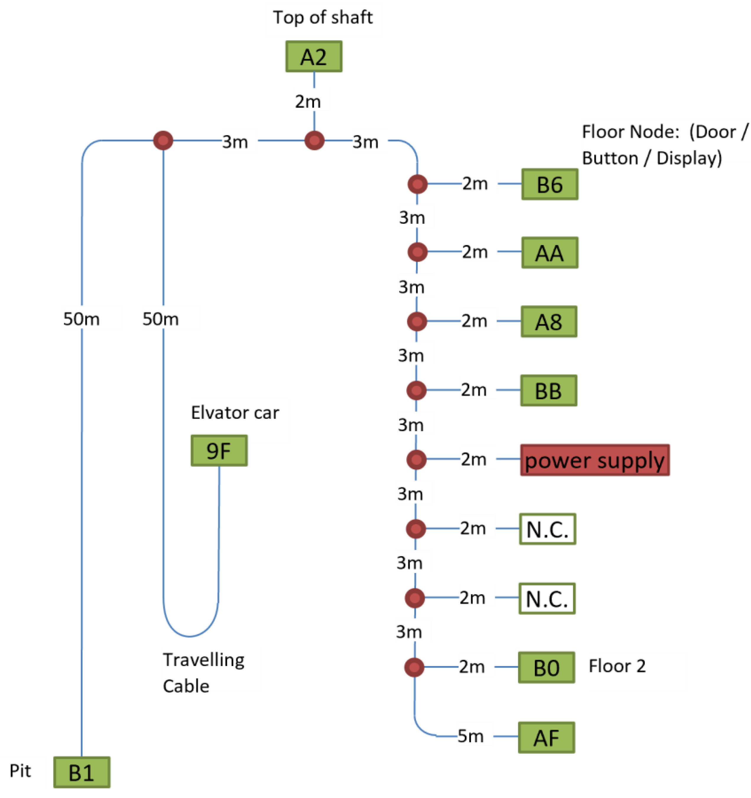
The wiring in an elevator control system has a topology not commonly found in residential wiring. The main difference is the regular shaft wiring with stubs (drop lines) on each floor to the equipment on the landing (door locks, displays, and push buttons). Therefore, the channel’s transfer function/frequency-dependent fading should be measured. To this end, we set up a model of a typical elevator cabling in the lab and measured the attenuation between different nodes over the relevant frequency range (Figure 2). An AC/DC power supply powered the network at a free branch, where no node was placed. The test network contained 9 nodes to simulate a network without a full population.
- All cables were unshielded twisted pair cables, excluding the traveling cable, which was straight.
- Due to the armored concrete in the lab premises, the traveling cable was placed on a wooden construction to have minimum coupling effects.
- All cables were placed within 1 m of each other. This was also applied for both sides of the U-turn in the traveling cable on the wooden construction.
- All T-connectors were simple connectors that generated reflections.
3.3.2. Packet Rate
To estimate the maximum number of packets per second, we verified the timings given in the G.hn link layer recommendation [3] with an oscilloscope for a point-to-point configuration sending ICMP echo requests (“ping” messages) from a PC connected to the DM to the EP’s IP address. We set the Ethernet interface to 100 Mb/s to avoid reaching the G.hn bandwidth limits (Figure 3). The measurement results are described in Section 5.2.
3.3.3. Latency Measurements
- (A)
- Measurement System
The measurement system was designed to measure the latency and jitter of communication systems. The test setup shown in Figure 4 is divided into a backend and a frontend. All connections in the backend and modem interfaces are 1000BASE-T (gigabit Ethernet). The daisy chain topology of the backend wiring supports easy field installation of the measurement system (e.g., in an elevator shaft).
- The system uses PC Engines’ apu2e4 single-board computers [22] as traffic generators and logging nodes. The APUs (accelerated processing units) have a quad-core 64-bit processor with 4 GB RAM and 3 Intel i210AT network controllers with hardware timestamping.
- The central test controller (CTC), a Linux PC, controls all APUs, which generate Ethernet packets according to predefined traffic patterns. The patterns define source and destination addresses, packet size, and the packet rate (with a certain randomization) of frames sent through the frontend system.
- All APUs are synchronized to the master clock within ± 1 μs using IEEE 802.1AS-2020, the TSN time synchronization protocol.
- APUs log timestamps of outgoing and incoming messages on port P1 facing the modem. The log files are sent to the CTC at the end of the test.
- CTC combines the log files with outgoing and incoming timestamps into a database accessible by the analysis software
The latency is defined as the difference between the receiving APU’s ingress and the transmitting APU’s egress timestamps, captured with the timestamping capability of the Intel i210AT network controllers. The reference point is the time when the SFD of an Ethernet frame passes P1 of the APUs.
- (B)
- Traffic patterns
For the investigations, we did not simulate the detailed communication patterns of an elevator control application. Instead, we measured point-to-multipoint (P2MP) and all-to-all (A2A) communication patterns to obtain more general and transferable results. Parameters are the number of nodes registered in the domain, the number of nodes actively participating in communication, the period of packet transmission (randomly varied by ± 25% to avoid beating effects), and the packet size (minimum/maximum Ethernet frame size).
Table 2 and Table 3 provide an overview of the resulting packet rates for the different configurations. The maximum rate that the system can transmit is approximately 1300 packets/s. The row “Packet rates w/relaying” is relevant for the SpiritGrid MAC algorithm described in Section 3.2.
The parameters were set because, with up to 8 nodes in the domain, the SpiritHN firmware allocates time slots (TS) fairly, whilst with more nodes, the DM claims every second TS for itself. The COTS hardware can support 14 nodes within a single, fully connected domain. The selected packet rates allow for statements to be made regarding lightly loaded networks and those close to or above the packet rate limit.
- (C)
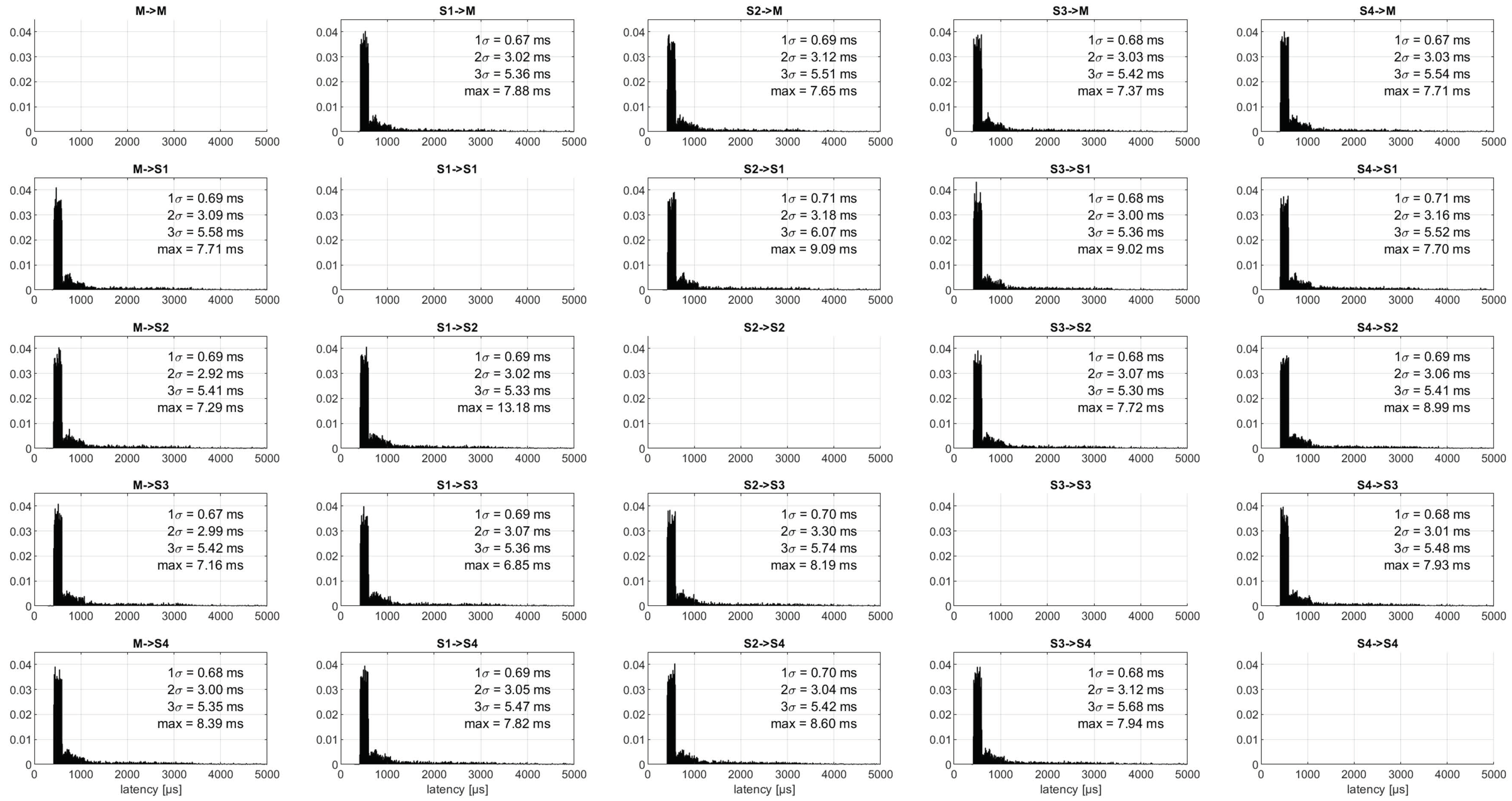
- Presentation of the latency measurement results
Latency measurement results were analyzed in histograms and probability plots. Figure 5 shows a histogram from a test with 5 nodes. Each column contains the latency histogram for frames sent by the respective node. The first column contains the frames sent by the domain master. A condensed format focuses on four summary values: the complete data set, DM-to-EP, EP-to-DM, and EP-to-EP data (Figure 6). These graphs provide an overview of the distribution of the latencies and whether there are differences related to the roles of the nodes (in this test, there were no significant differences). As additional information, we calculated the latency values corresponding to 1 and 3 σ values and whether any packets were lost. Although the distributions are not Gaussian, we used the sigma values as engineers are familiar with these metrics. The 1 and 3 σ values can be understood as the 68 and 99.7 percentile values of the measured latency distribution. The long tail typical for communication applications is difficult to analyze in this representation.
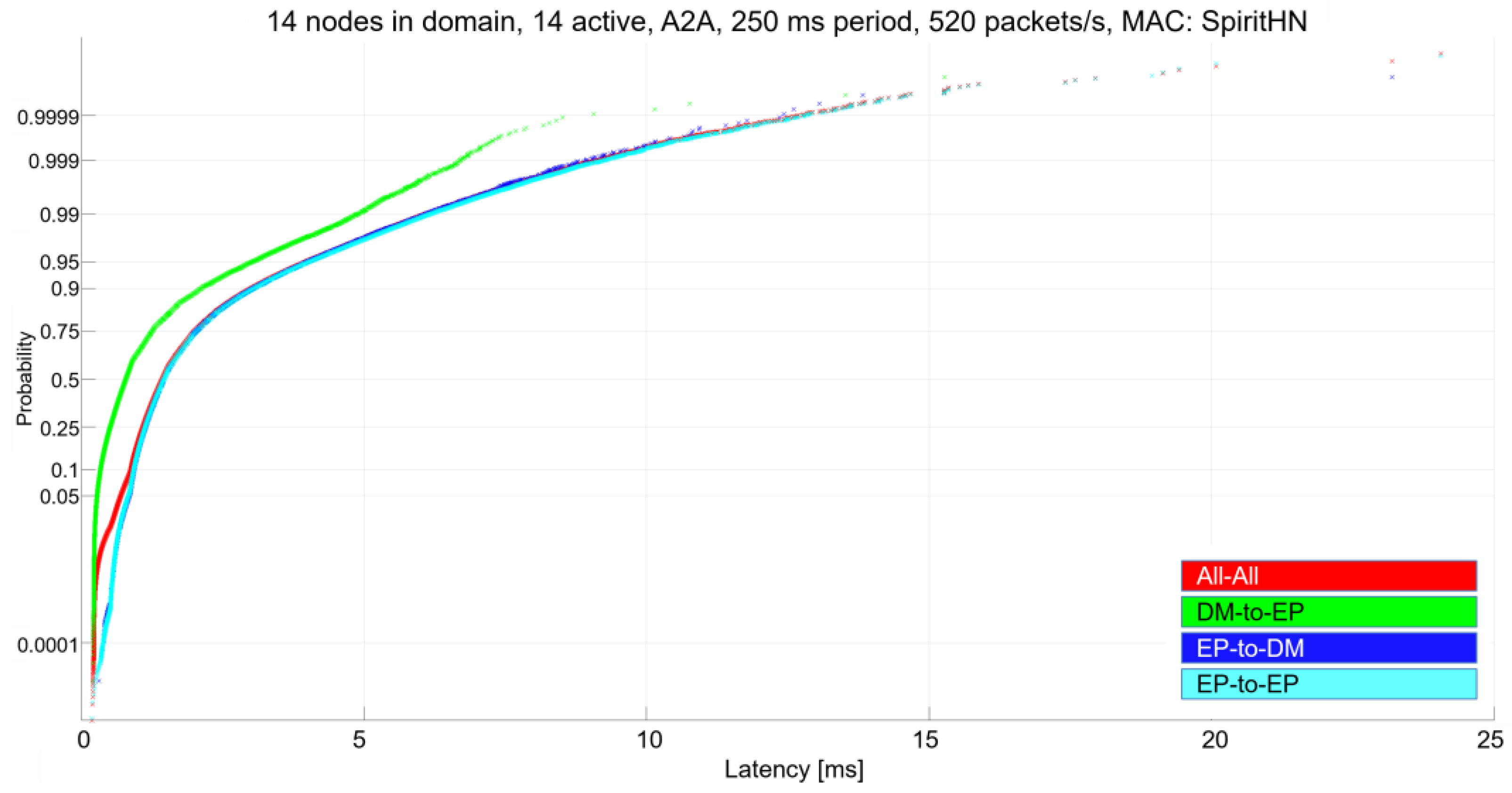
Considering that worst-case latencies are an important metric for IIoT control applications, another representation was also used. Probability plots use a nonlinear scale for the cumulative probability of a latency value on the vertical axis. This facilitates the visualization of outliers that may affect only the top ≤0.01% of the data sets. Figure 7 provides an example of this representation. In this case, the DM-to-EP communication has a lower latency than packets sent by the EP devices. Outliers >99.99% can be seen in all cases.
4. Sample Application: Elevator Control
Elevator control was selected as a representative use case for the following reasons:
- Cabling costs represent a significant proportion of the overall control system cost; thus, reducing the number of cables is economically relevant.
- Performance requirements are moderate compared to high-end industrial automation systems.
- BPLC is currently used in elevators. However, these existing use cases do not cover control of the elevator operation itself. Instead, they typically provide a separate communication means from a gateway mounted in the head of the shaft to the elevator car for voice and video transmission, or they interconnect elevator and door terminals throughout a building that belong to a system that optimizes the people flow through the complete building.
4.1. Elevator Control
To control an elevator, four different main tasks can be distinguished:
- Trip control (movement of the car and doors)
- Passenger call handling and signaling
- Emergency communication, either to a central service center or to a local service desk
- Maintenance and service
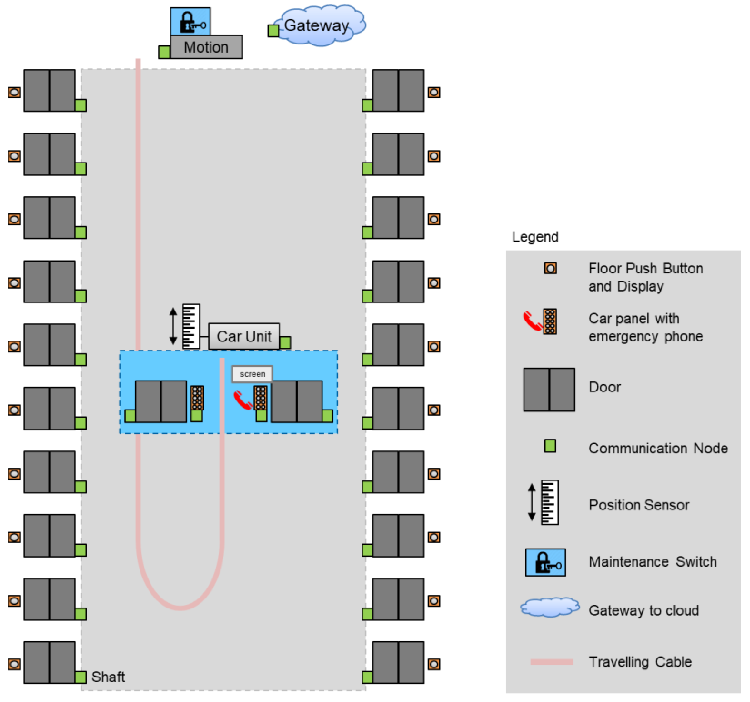
Figure 8 presents the various nodes that form the control system of an elevator with double entrance sides. Using a middleware on these nodes, higher layer functions like system supervision or decision-making on movement sequence can be allocated to any node with sufficient CPU capacity. In our example, these central functions are allocated to the car node. On top of the shaft, one node (motion) controls the inverter and the motor, while a second node acts as a remote gateway. Additionally, there are nodes on each landing. On the car, there is one controller node for each door and one for each operating panel; one of these panels contains the emergency phone.
Trip Control: A trip comprises a sequence of commands: the doors are closed and locked, torque in the drive is built up (pre-torquing), and the brakes are opened. The car position is periodically sent to motion. The car travels to the destination floor, brakes are locked, doors are opened, and the torque is removed. Car movement and position are signaled on the different landings.
Call handling and signaling: In standard operation, users request to be picked up on a landing by pressing the correct push button (up/down), and inside the car, they select the destination floor. Car position and direction of the movement are optionally signaled on the landings. The central node decides on the sequence of the trips if multiple call requests are pending.
Emergency communication: In case of problems with the elevator, entrapped passengers can use the emergency phone to call a service center or a service desk. The internet gateway ensures the connection for these calls by using cellular communication (LTE or 5G) or an in-house telephone system. Hence, there must not be a common failure in the elevator movement and emergency communication; that is, either the elevator can move and release passengers, or the emergency phone must work.
Maintenance and service: Maintenance and service, including commissioning, generates different requirements. At the end of the installation phase, the elevator performs a learning trip where the system measures the exact position of the doors. This helps avoid time-consuming creep phases when approaching a floor during operation. Access to all nodes for log file and variable tracing must be supported for remote maintenance and service. Also, an intercom system between the elevator pit at the bottom of the shaft, the top of the car, and the top of the shaft/machine room is part of the maintenance and service requirements.
4.2. Data Traffic Patterns and Performance Requirements
The dominating traffic patterns for the four scenarios listed above are:
Trip control: At the beginning and end of the trip, a sequence of commands and responses occurs between the car node and other nodes (motion to build up torque and release brakes, doors to open/close/lock). During the trip, position information is exchanged cyclically every 15 ms between the car node and motion [23].
Call handling and signaling: Call acknowledgment (illuminating the push button or signaling that a call/trip is not allowed) must be perceived reasonably quickly for the passengers’ perception; 100 ms is typical. However, it is not considered critical if this time is occasionally violated. Communication follows a star pattern between the central node (car node), landing nodes, and car panels.
Emergency communication: The quality of emergency phone voice communication with entrapped passengers must be sufficient to reduce and not increase the stress level of entrapped persons. Within the elevator system, this is a point-to-point communication between a car panel and the gateway node.
Maintenance and service: Firmware download to all nodes of the elevator control system within 15 min (elevator not operational) or in the background during normal operation, with less stringent time requirements. In the latter case, the new firmware will only be distributed to the nodes. Activation will require maintenance staff on site. There may also be regions where this is impossible and prohibited by law. For extended monitoring, log files are regularly transmitted from a subset of the control system nodes to a central node (car node or gateway). The learning trip requires unidirectional, low-latency transmission of short packets each time a floor is passed to the motion unit to calibrate the system. The elevator car moves at a constant speed throughout the shaft to ensure an efficient process and avoid errors due to slippage.
System self-supervision: In all scenarios, the central node exchanges heartbeat messages with every other node in the system. The heartbeat interval is 1–3 s (request and response).
Table 4 lists the essential characteristics and most challenging requirements for the different communication flows within the elevator control system.
5. Results
5.1. Channel and Throughput
For the measurement layout described in Section 3.3.1 and Figure 2, the channel characteristics between the car node, top-of-shaft, and floor 2 were measured. Figure 9 shows the power spectral density (PSD) measured by the G.hn modems. The notches in the PSD in the 0–30 MHz range and >80 MHz were as expected from radio spectrum regulations. At 30 MHz, the regulatory PSD limit is reduced by 30 dB and the power density is reduced accordingly. While the channel from the car node to the top-of-shaft was good, the spectrum to floor 2 exhibited selective fading caused by the regular structure of the stubs on each floor. Section 5.2 shows bandwidth measurements for the two channels “car node to the top-of-shaft” and “floor 2 to the top-of-shaft”. These were selected because top-of-shaft is the destination/source of traffic with the highest requirements on throughput.
To investigate the behavior at different data rates, we measured the PSD with a Rohde & Schwarz spectrum analyzer R&S® ZVL6 for user data rates of 10 and 250 Mbit/s between the car node and top-of-shaft (Figure 10). The full available spectrum between 0 and 80 MHz was used for both speeds.
5.2. Physical Layer: Throughput and Packet Rate
Using iperf3, we identified the maximum data rate by overloading the system by transmitting UDP traffic with 1 Gbit/s between two nodes. On the good channel, an average throughput of 525 Mbit/s was achieved between the top-of-shaft and car node. On the bad channel, between the top-of-shaft and floor 2, the average was 166.5 Mbit/s, with a minimum of 70.4 Mbit/s. Figure 11 shows the measured throughput for the SISO operation of the network for the bad and good channels. The data rates are more than sufficient for the requirements of the application. Accordingly, we did not investigate MIMO further.
As described in Section 3.3.2, we compared the values from the G.hn recommendations with oscilloscope recordings. The resulting G.hn packets had two payload symbols; three time slots were not used for transmission after the ACK. Figure 12 compares the values from the G.hn recommendations and our measurements. Figure 13 shows the signal measured on the wire and the interpretation of the different active phases.
The values per G.hn specification are as follows:
| Symbol duration | tSym | 40.96 µs |
| Guard duration | tG | 10.24 µs |
| Inter frame gap (minimum value) | tIFG | 90 µs (default minimum) |
| Acknowledgement inter frame gap | tAIFG | 122.8 µs |
| Time Slot (TS) duration | tTS | 35.4 µs |
The shortest possible data packet comprises a single payload symbol. To obtain the shortest duration for complete packet transmission and thus the maximum theoretical packet rate, our measured values were corrected by one symbol duration, including guard time. Thus, the minimum time for a packet transfer was 462 µs. The theoretical maximum packet rate was approximately 2200 packets/second. This value cannot be reached in real systems as channel time is required for other functions like MAP transmission, guard times of transmit opportunities, channel estimation, and noise level measurements. Our estimation for the maximum packet rate was approximately 1300 packets per second.
The precise value is difficult to determine due to the flexibility in G.hn data transmission. G.hn can accumulate multiple user frames to the same G.hn destination within a single packet. The number of payload symbols per packet varies; the packet duration may be up to a few milliseconds. Also, the bit loading and FEC ratio can be increased. Therefore, in terms of Ethernet packets at the G.hn network boundaries, data is not necessarily lost if the G.hn packet rate is exceeded. Instead, packets will arrive with a higher latency. On the receiver side, the user frames in the aggregated G.hn packet are sent as individual Ethernet packets, transparent to the connected Ethernet devices. The received packets will have experienced massively different latencies for the user processes on the end devices.
5.3. Medium Access: Latencies
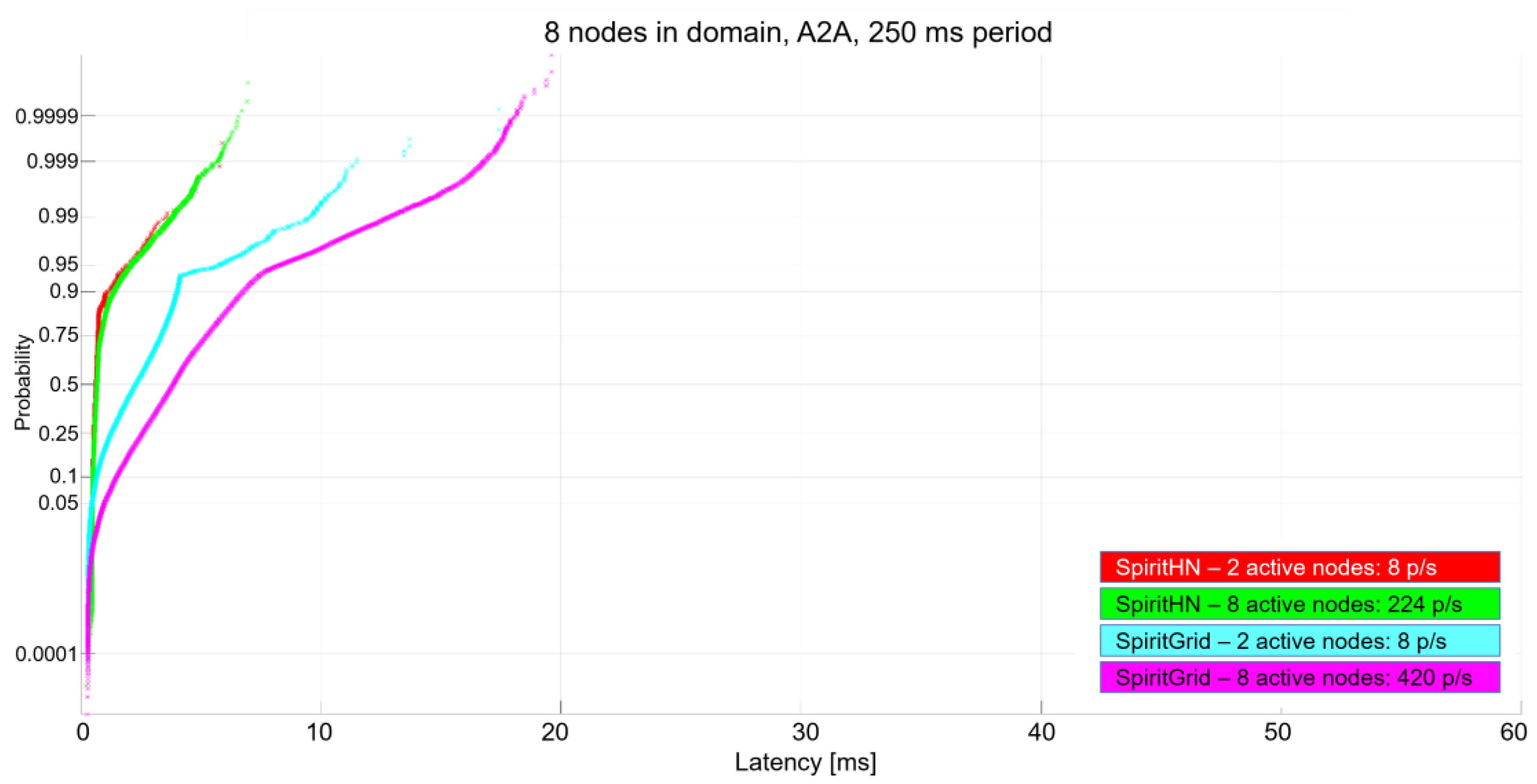
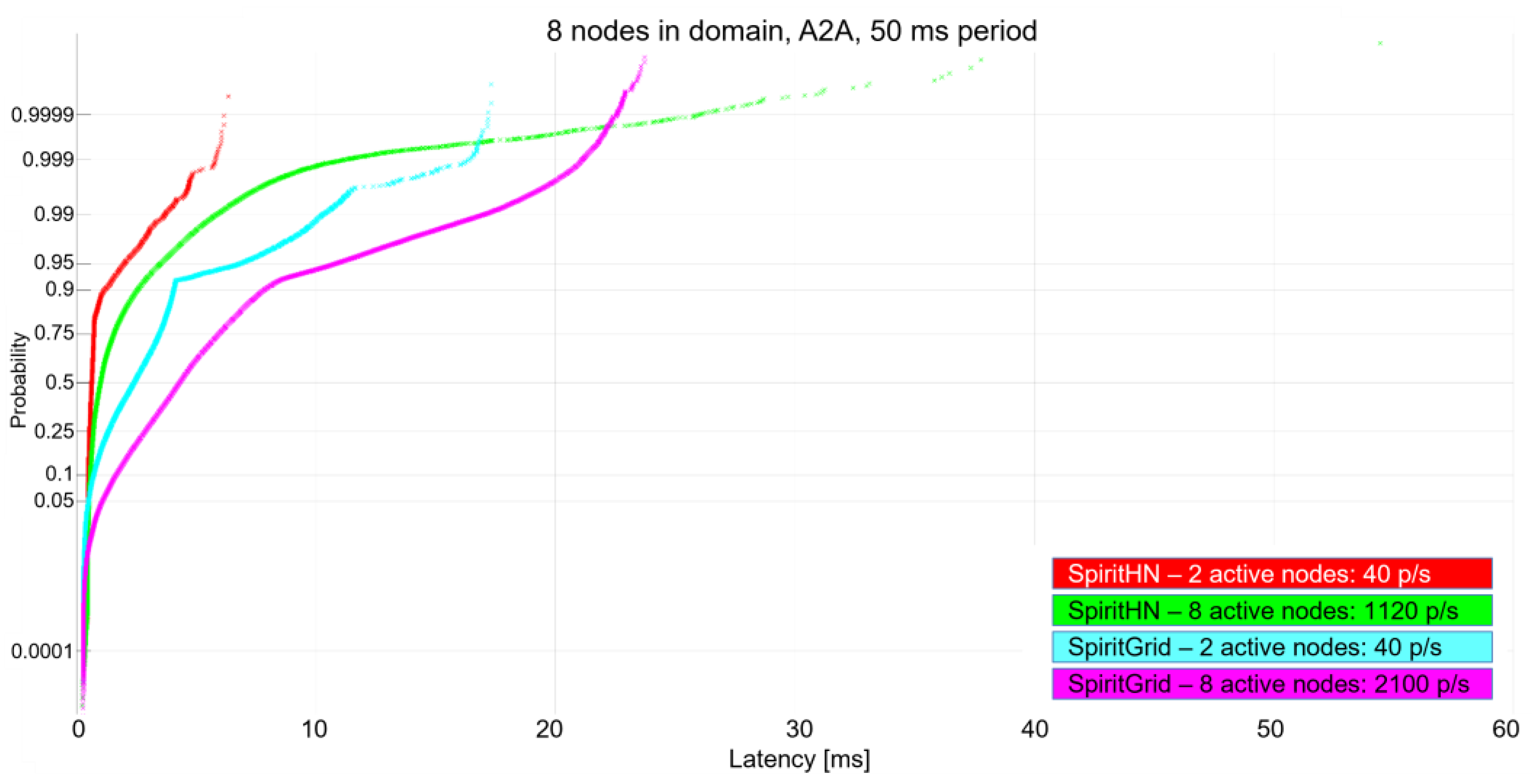
We first measured latencies for a G.hn domain with eight nodes. This is the maximum domain size, where SpiritHN provides a fair medium allocation. For the all-to-all (A2A) communication pattern, Figure 14 shows the results for 250 ms packet generation rates with two or eight active nodes in the domain. Figure 15 shows the results for an increased packet generation rate of 50 ms. In cases with a moderate overall packet rate (Figure 14 and Figure 15 with two active nodes), SpiritHN performed better than SpiritGrid regarding average and worst-case latency.
With eight active nodes sending one packet to every other node every 50 ms, the situation changed, and the worst-case latency with SpiritHN reached 40 ms (green curve in Figure 15). Meanwhile, SpiritGrid (magenta) did not exceed 25 ms latency.
If the number of nodes that form the domain increased further, the performance of SpiritHN dropped significantly. Figure 16 shows the plots for the same traffic patterns as Figure 15, the performance of SpiritHNFair, and an extreme case with 14 active nodes sending packets to each other every 50 ms. SpiritHN performed poorly with long tails, even for only two active nodes. SpiritHNFair performed better, however, for eight nodes, a long tail distribution was visible. SpiritGrid is the only MAC algorithm that coped with the highest offered traffic load (yellow, blue, and black in Figure 16). SpiritGrid took advantage of the aggregation and scaling properties of G.hn: all-to-all traffic was effectively converted into point-to-multipoint traffic. When an EP was polled, the EP transmitted a G.hn packet to the DM with whatever aggregated user data was available for transmission. When polling an EP, the DM aggregated and transmitted pending user data addressed to that EP within a single packet. This massively reduced the effective packet rate. In contrast, with SpiritHN, the maximum packet rate was exceeded, the system was overloaded, and packets were lost. Table 5 summarizes the properties of the three MAC algorithms.
The three MAC algorithms did not meet the most stringent requirement of 3 ms for communication between the car unit and motion. Therefore, we investigated the performance of G.hn’s phone line profile. To this end, we increased the packet generation rate to 21 ms and compared the performance of the powerline profile to the phoneline profile (Table 6). Compared to the powerline profile, the phoneline profile has twice the subcarrier spacing and half the symbol duration. This, and the limited number of nodes, helped achieve the required 3 ms maximum latency. With both profiles, no packets were lost.
6. Discussion
The available hardware components exhibited certain limitations compared to our expectations based on the G.hn recommendations; the two main points are:
- The implemented and available MAC algorithms for the G.hn powerline profile are relatively simple, and many of the advanced features described in the G.hn recommendations are not implemented or controllable. (Note: For the phone line and coax profiles, more advanced features are available)
- The number of nodes with direct communication and the size of a flat G.hn domain is limited to 14.
Q1:
Are today’s COTS BPLC components suitable for IIoT applications? Which worst-case latencies can be expected?
The channel measurements show that, for the intended application, communication with all nodes connected to the cabling is possible, and the bandwidth is sufficient. From this perspective, G.hn could be used for automation applications. We elaborate on the “buts” in the description of the proposed architecture below.
6.1. Proposed Architecture
For the elevator control application, two critical aspects require further evaluation and result in our proposed architecture:
- latency distributions, and
- the resilience requirement, “No single point of failure impacting movement and emergency communication at the same time.”
Worst-case latencies
The domain size (i.e., the number of nodes that participate in a domain and have time slots assigned) plays a vital role in the worst-case latencies:
With up to eight participating nodes, traffic with a generation rate of four packets per second per node is best handled by the standard MAC algorithm for home networking, SpiritHN; latencies < 10 ms are achieved. With increasing traffic rates, worst-case latencies increase to 25 ms, and SpiritHN—the standard round-robin MAC—is outperformed by SpiritGrid if all nodes communicate. Finally, for even larger systems, only SpiritGrid performs reliably with high traffic loads, and worst-case latencies remain <40 ms and <30 ms for 99.9% of packets sent.
The 3 ms requirement for communication between the car unit and motion cannot be satisfied using the G.hn powerline profile. A possible solution is discussed in the proposed architecture for zone 1 below.
Resilience
The DM is critical for resilience. With SpiritGrid, the role of the DM is fixed and cannot be changed (A specific FW version for the DM is required). With SpiritHN, the DM role can be activated on any node, and failover mechanisms are implemented. Therefore, SpiritHN should be used for the communication path between nodes where a single point of failure cannot be accepted.
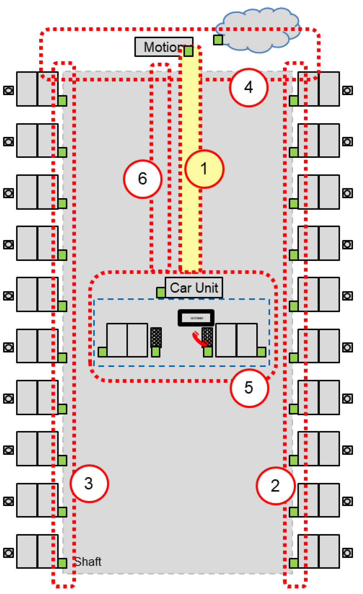
In the elevator control topology, this is the zones 4, 5, and 6 on the system partitioning shown in Figure 17. They can be covered by a single G.hn domain. The GW and emergency phone on the car are not required for movement, so their failure will not impact travel. If the car node fails, assuming the DM is instantiated, the GW or emergency phone can take over that role. Entrapped passengers in the car can still make emergency calls over these zones if backup power for the gateway and emergency phone nodes is available.
For the landing door connections (zones 2 and 3), a separate G.hn domain is required due to the limitation of SpiritHN to 14 nodes. Hence, SpiritGrid is a good option in this scenario; if SpiritGrid had a reconfiguration feature so that the DM role was not fixed to one physical node, zones 4, 5, and 6 could be included in the SpiritGrid domain. Measurements with two subdomains showed that the latencies did not exceed 60 ms for a scenario with 14 nodes and a high traffic load of 50 ms A2A.
Zone 1 in Figure 17 is designed as a separate link between the car and motion, where a 3 ms latency is a requirement. Here, we proposed including a separate twisted wire pair in the traveling cable and using the phone line profile of G.hn (Table 6).
For this point-to-point link, other technologies, like Ethernet (e.g., 100BASE-TX for up to 100 m or 10BASE-T1L for single-pair Ethernet (SPE) up to 1500 m), would be viable solutions. The clear advantage of the G.hn phone line profile is the longer reach compared to 100BASE-TX and the scalability in bandwidth compared to 10BASE-T1L.
Q2:
How can system and application design facilitate the use of BPLC for IIoT?
We have seen that the latency variations can be significant in the order of tens of milliseconds. This means that the application software functions of the IIoT control system must be able to handle late-arriving messages. Existing application software developed for RS-485 or CAN-based systems often assumes a fixed delay between the sampling at a sensor node and the arrival at the main control node. If this is the case, the jitter of the G.hn communication system may impact the quality of closed control loops or have other negative effects.
A potential mitigation is synchronizing the complete control system with, for example, a simplified version of NTP. An accuracy of better than 1 ms between the nodes in the system should be achievable. The control logic can manage jitter and react accordingly with time-stamped sensor data.
Communication system partitioning plays a significant role. Latencies increase drastically with the number of participating nodes in a G.hn domain, even if they do not produce traffic. System designers must consider this and plan for filters and domain separation accordingly.
We did not observe packet loss for normal traffic loads due to the underlying acknowledgments implemented in the G.hn link layer protocols. At the same time, the maximum packet rate is limited and strongly related to worst-case latencies in the G.hn system. Hence, it may be advisable to avoid application layer protocols that generate frequent acknowledgment telegrams, such as TCP or MQTT over TCP, and use connectionless, UDP-based communication for time-critical data. Log file transfers and FW upgrades may still advantageously use these protocols when the elevator is not moving.
6.2. Advantages and Disadvantages of BPLC for IIoT Applications
We observed several advantages in applying BPLC with COTS components for IIoT applications. However, depending on the requirements of an application, the benefits may be outweighed by the drawbacks of the technology.
6.2.1. Benefits
With BPLC, existing power cables (AC and DC) can be used for communication. This is attractive for retrofits of existing plants. Wiring costs can also be significantly reduced for new installations when BPLC is used. In addition to the ability to use existing power supply lines, BPLC does not require dedicated bus terminations with a characteristic impedance, and the sensitivity to stub length lines is much lower compared to CAN.
With BPLC, there is no need to provide an Ethernet switch port for each connected node, bandwidth is available in certain situations (maintenance/FW download vs. operative mode), and the physical range is higher than the standard electrical Ethernet link distance of 100 m. Walls and reflections in elevator shafts with metallic components and a moving car are problematic for wireless technologies, however, they are not challenging for BPLC.
Latency and latency variations are comparable to wireless LANs; wired communication technologies such as fieldbuses typically have better control over latency but much lower data rates. Meanwhile, industrial Ethernet typically requires considerable expertise, tools, and additional network equipment, such as managed Ethernet switches.
6.2.2. Cons
G.hn was not designed to support real-time traffic and bounded latency. Rather, the focus is on internet access and home networking with high data rates for specific nodes in the network, as well as smart grid-type applications where response time requirements are moderate.
While minimum and average latency can be very low, latency outliers in the double-digit ms range must be expected in all traffic situations. Applications must deal with these outliers; not all applications will do so gracefully. The number of packets that can be sent is also limited; transmission of the shortest packet, including acknowledgment, takes 0.46 ms. COTS components on the market have limitations on the number of nodes that can communicate directly with each other; for the components we used, this limit is 14 nodes in a G.hn domain.
For setups with power consumers on DC lines, and when multiple domains are required, filtering circuits must be installed, which increases system cost. Combined with the cost of the G.hn component, this could outweigh the potential cost savings in the wiring.
For more demanding applications, such as those we excluded in our research question Q1, we do not believe BPLC is a viable alternative. These applications require real-time Ethernet today and, in the future, TSN, or new generations of wireless communication technologies that enable truly deterministic communication.
The tradeoff between component cost and savings on the wiring must be evaluated for a given application.
6.3. Future Work
Our research raised various questions and potential areas for future research regarding further investigations into aspects of G.hn technology.
We identified gaps between expectations a system designer may have when reading standards and existing implementations, which may implement only a selection of available features. For example, one idea was to use statically assigned transmit opportunities for priority traffic, however, none of the MAC algorithms for the G.hn powerline profile supported this feature. This is where additional research on the benefits of these advanced features could help motivate vendors to implement them. Configuring data streams requiring low latency at comparatively low data rates should result in more frequent TS allocation by the DM to the EP devices that generate these streams.
A spectrum-slicing approach may be beneficial to avoid crosstalk between different G.hn domains. For example, the lower frequency spectrum could be reserved for nodes that experience higher attenuation, such as the shaft wiring; the upper part of the spectrum could be used for nodes that are relatively close to each other, such as the nodes on the car and the top-of-shaft equipment.
In our response to research question Q2, we mentioned a simplified version of NTP. A TSN standard for time synchronization, IEEE 802.1AS, the generalized Precision Time Protocol gPTP [24], references G.hn as a “coordinated shared medium.” The implementation of this standard will enable time synchronization of sensor nodes with microsecond accuracy. This will allow highly accurate timestamping of sensor data in sensor nodes and open up the application of G.hn for distributed synchronized measurement systems.
From the elevator control use case perspective, a feasible alternative to G.hn may be multidrop Ethernet 10BASE-T1S. Currently, this technology is limited to eight nodes and a 25 m segment length. However, work is underway at IEEE [25] to extend this system to 16 nodes and a 50 m reach. 10BASE-T1S does not require switches and could be an alternative for elevator car and shaft communication.
For the independent emergency phone, the applicability of wireless solutions should be investigated, removing the “single point of failure” resilience requirement for the G.hn network.
Power consumption is another aspect that warrants further research. The development of energy-efficient systems is an ever-growing challenge. The impact and applicability of power-saving features, available today in the G.hn components, on the performance, system startup time, and reaction to user input require additional investigation.
Beyond the scope of our investigation into the use of COTS components, a possible extension of the data link layer definitions in the G.hn recommendations can be envisioned. For applications where the late arrival of data is equivalent to data loss, an option to disable the ARQ mechanism for a specific traffic class could be defined. Criteria could be a specific Ethertype or VLAN tag. This approach is used, for example, with voice over LTE (VoLTE) in mobile communication systems.
7. Threats to Validity
Although we attempted to mimic the real environment of an elevator control system in our lab setup, several technical and commercial risks were identified for implementing and using BPLC for elevator control.
The transfer function must be confirmed by measurement in real elevator shafts. There are various cabling topologies with different parameters, including the stub length on the floors. This may impact the channel quality. However, as our measurements show, these effects are primarily observed in the shaft wiring, where only short packets are exchanged. Thus, even if the bandwidth is significantly reduced, the size of transmitted packets and the packet rate should not change significantly.
The crosstalk between the traveling cable and shaft wiring may have a two-fold impact. At the physical layer, it will result in an increased noise floor. One mitigation could be to use a twisted wire pair in the traveling cable to minimize the demands on the shaft wiring. On the MAC layer, we proposed to operate the car node—top-of-shaft area as one G.hn domain and the landing cabling as a second domain. Existing coexistence mechanisms designed for home networking applications will increase latency by allocating some available time to the other domain. Although there are options to disable this feature, we did not evaluate them.
Noise from the machine and frequency converters may also impact the useable modulation order and overall bandwidth. Additional filters may be required for large consumers. Also, signal filtering with appropriate electronic components may be required if the G.hn network is segmented, as suggested in Figure 17.
Overall, these strategies to improve and separate channels will have a cost impact, and an assessment of the cost-benefit of using COTS consumer technology will be required. At least in the introductory phase, the cost will be significantly higher than existing solutions, e.g., with CAN bus, which is often integrated into microcontrollers and requires relatively simple electronic components.
8. Conclusions
Our work shows that G.hn, with existing COTS components, can fulfill the requirements for an industrial automation system. However, several limitations and prerequisites must be considered in the system and application design.
On dedicated links, latencies with an upper limit of 3 ms can be achieved. With suitably selected MAC algorithms, the latency limits for larger domains (up to 14 nodes) are in the range of 35 ms. The measured throughput was in the double-digit Mbit/s range even if the physical channel suffered frequency-selective fading and parts of the spectrum could not be used. A possible limiting factor is the maximum packet rate of approximately 1300 packets per second. However, G.hn can combine several user packets to the same G.hn destination in a single G.hn packet. In G.hn domains with more than 14 nodes, some nodes cannot communicate directly. In these cases, the DM must act as a relay.
The advantages of employing G.hn in IIoT are its flexibility in data rate, the re-use of existing power supply lines, and the free topology of the cabling, even if separate cabling should be used. Also, no switches are required compared to Ethernet-based systems.
Properties of G.hn and COTS components that must be carefully reviewed for a specific application are the latency distribution with its considerable variation, which the application must handle, and the limited number of nodes that can directly communicate. Also, due to the limited packet rate, TCP as an application protocol that generates additional traffic for acknowledgments should be avoided for time-critical sensor data transfer.
For a specific application area, many technical aspects will require closer investigation. For the elevator case, the single point of failure is an example of such an investigation. Other aspects are the need for filtering circuits to separate G.hn domains if latencies are critical, consumers with large input capacities and thus low input impedances on DC lines, and costs in general. RS-485, CAN, and Ethernet interfaces are often already integrated into microcontrollers. Power consumption is another important aspect that requires further investigation.
A general learning of our investigations is that COTS components may not implement the full scope of a standard and have limitations that can only be explored with extensive experiments.
Author Contributions
Conceptualization, K.B. and M.O.; Investigation, K.B. and S.D.; Writing—original draft, M.O.; Writing—review & editing, K.B., S.D. and M.O.; Supervision, M.O.; Project administration, M.O. All authors have read and agreed to the published version of the manuscript.
Funding
This research was funded by Innosuisse—Swiss Innovation Agency, grant number 34589.1 IP-ENG. Open access funding provided by ZHAW Zurich University of Applied Sciences.
Institutional Review Board Statement
Not applicable.
Informed Consent Statement
Not applicable.
Data Availability Statement
The used equipment with relevant FW versions is listed in Appendix A. Please contact the authors directly to request access to the raw measurement data.
Conflicts of Interest
The authors declare no conflict of interest.
Abbreviations
| 1000BASE-T | Gigabit Ethernet (1 Gbit/s over four twisted wire pairs) |
| 100BASE-TX | Fast Ethernet (100 Mbit/s over two twisted wire pairs) |
| 10BASE-T1L | Ethernet Standard for 10 Mbit/s over a single twisted wire pair |
| 5G | 5th Generation Mobile Network Standard |
| A2A | All-to-All |
| AC | Alternating Current |
| ACK | Acknowledgement |
| AES | Advanced Encryption Standard |
| APU | Accelerated Processing Unit |
| ARQ | Automatic Repeat Request |
| BPLC | Broadband Powerline Communication |
| BPSK | Binary Phase Shift Keying |
| CAN | Controller Area Network |
| CBTS | Contention Based Time Slot |
| CFTS | Collision Free Time Slot |
| CFTXOP | Collision Free Transmit Opportunity |
| COGS | Costs of Goods Sold |
| COTS | Commercial off the Shelf |
| CPU | Central Processing Unit |
| CTC | Central Test Controller |
| DC | Direct Current |
| DM | Domain Master |
| EP | End Point |
| FEC | Forward Error Correction |
| FW | Firmware |
| Gbit | Gigabit |
| GW | Gateway |
| ICMP | Internet Control Message Protocol |
| IEC | International Electrotechnical Commission |
| IEEE | Institute of Electrical and Electronics Engineers |
| IioT | Industrial Internet of Things |
| IoT | Internet of Things |
| IP | Internet Protocol |
| ITU-T | International Telecommunication Union—Telecommunication Standardization Sector |
| LDPC | Low Density Parity Check |
| LTE | Long-Term Evolution (4th Generation Mobile Network Standard) |
| MAC | Medium Access Control |
| MAP | Media Access Plan |
| Mbit | Megabit |
| MIMO | Multiple Input Multiple Output |
| MQTT | Message Queuing Telemetry Transport |
| MSG | Message |
| NTP | Network Time Protocol |
| OFDM | Orthogonal Frequency Division Multiplexing |
| P2MP | Point to Multipoint |
| PC | Personal Computer |
| PHY | Physical Layer |
| POF | Passive Optical Fiber |
| PSD | Power Spectral Density |
| QAM | Quadrature Amplitude Modulation |
| QoS | Quality of Service |
| RAM | Read-Only Memory |
| RTE | Real Time Ethernet |
| RTS/CTS | Request to Send/Clear to Send |
| SFD | Start Frame Delimiter |
| SISO | Single-Input Single Output |
| SPE | Single Pair Ethernet |
| SpiritGrid | Spirit Grid Firmware/MAC Algorithm |
| SpiritHN | Spirit Home Network Firmware/MAC Algorithm |
| STXOP | Shared Transmit Opportunity |
| TCP | Transmission Control Protocol |
| TDMA | Time Division Multiple Access |
| TS | Time Slot |
| TSN | Time Sensitive Networking |
| TXOP | Transmit Opportunity |
| UDP | User Datagram Protocol |
| VoIP | Voice over IP |
| VoLTE | Voice over LTE |
Appendix A
To obtain the measurements presented in this article, the following equipment was used:
BPLC equipment: MaxLinear G.hn modem evaluation kits.
| Powerline profile | MaxLinear DW920 G.hn Wave-2 Powerline Evaluation Kit Firmware versions: SpiritHN v7.8 SR5 r619+38 SpiritGrid v7.10 r780+2 | Product homepage: https://www.maxlinear.com/product/connectivity/wired/g-hn/evaluation-kits/dw920 (accessed on 20 August 2023) |
| Phone line profile | MaxLinear. DW920 G.hn Wave-2 Phone Line Evaluation Kit Firmware version: Firmware version SpiritP2MP v7.8 r619+19 | Product homepage: https://www.maxlinear.com/product/connectivity/wired/g-hn/evaluation-kits/dcp962p (accessed on 20 August 2023) |
PSD measurements (Figure 9)
| Network Analyzer | The measurements were done with the SNR monitor integrated in the DW920 powerline modems. |
PSD measurements (Figure 10)
| Network Analyzer | Rohde & Schwarz Vector Network Analyzer, 6 GHz, test ports: N (f), 50 W, R&S®ZVL6 | Product homepage: https://www.rohde-schwarz.com/ch-en/products/test-and-measurement/network-analyzers/rs-zvl-vector-network-analyzer_63493-9014.html (accessed on 8 November 2023) |
Throughput measurements (Figure 11)
| Network traffic generation | iperf3 | Product homepage: https://iperf.fr/ (accessed on 8 November 2023) |
| Laptop Computers | HP Elitebook 840 G5 |
Packet transmission and acknowledgements (Figure 13)
| Oscilloscope | Rohde & Schwarz Oscilloscope RTO1014, 1 GHz bandwidth, 10 GS/s | Product homepage: https://www.rohde-schwarz.com/ch-en/products/test-and-measurement/oscilloscopes/rs-rto1000-digital-oscilloscope_63493-191808.html (accessed on 8 November 2023) |
Latency measurements system
| Traffic generation and logging units | PC Engines® apu2e4 Debian Linux version | Product homepage: https://www.pcengines.ch/apu2.htm (accessed on 31 August 2023) |
| Data evaluation | Matlab Python | www.mathworks.com www.python.org (accessed on 8 November 2023) |
References
- Rahman, M.M.; Hong, C.S.; Lee, S.; Lee, J.; Razzaque, M.A.; Kim, J.H. Medium access control for power line communications: An overview of the IEEE 1901 and ITU-T G.hn standards. IEEE Commun. Mag. 2011, 49, 183–191. [Google Scholar] [CrossRef]
- ITU. Recommendation ITU-T G.9960 (2018)—Amendment 3; Unified High-Speed Wireline-Based Home Networking Transceivers—System Architecture and Physical Layer Specification Amendment 3; International Telecommunication Union: Geneva, Switzerland, 2022. [Google Scholar]
- ITU. Recommendation ITU-T G.9961 (2018)—Amendment 4; Unified High-Speed Wireline-Based Home Networking Transceivers—Data Link Layer Specification Amendment 4; International Telecommunication Union: Geneva, Switzerland, 2022. [Google Scholar]
- ITU. Recommendation ITU-T G.9962 (04/2023); Unified High-Speed Wire-Line Based Home Networking Transceivers—Management Specification; International Telecommunication Union: Geneva, Switzerland, 2023. [Google Scholar]
- ITU. Recommendation ITU-T G.9963 (06/23); Unified High-Speed Wireline-Based Home Networking Transceivers—Multiple Input/Multiple Output Specification; International Telecommunication Union: Geneva, Switzerland, 2023. [Google Scholar]
- Xing, L. Reliability in Internet of Things: Current Status and Future Perspectives. IEEE Internet Things J. 2020, 7, 6704–6721. [Google Scholar] [CrossRef]
- Bures, M.; Klima, M.; Rechtberger, V.; Ahmed, B.S.; Hindy, H.; Bellekens, X. Review of Specific Features and Challenges in the Current Internet of Things Systems Impacting their Security and Reliability. arXiv 2023, arXiv:2101.02631. [Google Scholar]
- IEEE TSN Task Group. Available online: https://1.ieee802.org/tsn/ (accessed on 24 October 2023).
- Dominiak, S.; Serbu, S.; Schneele, S.; Nuscheler, F.; Mayer, T. The Application of commercial Power Line communications technology for Avionics Systems. In Proceedings of the 31st Digital Avionics Systems Conference, Williamsburg, VA, USA, 16–20 October 2012. [Google Scholar]
- De Oliveira, R.M.; Vieira, A.B.; Latchman, H.A.; Ribeiro, M.V. Medium Access Control Protocols for Power Line Communication: A Survey. IEEE Commun. Surv. Tutor. 2019, 21, 920–939. [Google Scholar] [CrossRef]
- Mudriievskyi, S.; Lehnert, R. Performance evaluation of the G.hn PLC PHY layer. In Proceedings of the 18th IEEE International Symposium on Power Line Communications and Its Applications, Glasgow, UK, 30 March–2 April 2014; pp. 296–300. [Google Scholar] [CrossRef]
- Pereira, S.C.; Caporali, A.S.; Casella, I.R.S. Power line communication technology in industrial networks. In Proceedings of the 2015 IEEE International Symposium on Power Line Communications and Its Applications (ISPLC), Austin, TX, USA, 29–31 March 2015; pp. 216–221. [Google Scholar] [CrossRef]
- Bucci, G.; Ciancetta, F.; Fiorucci, E.; Fioravanti, A.; Prudenzi, A. A Pulse Oximetry IoT System Based on Powerline Technology. In Proceedings of the 2019 II Workshop on Metrology for Industry 4.0 and IoT (MetroInd4.0&IoT), Naples, Italy, 4–6 June 2019; pp. 268–273. [Google Scholar] [CrossRef]
- ITU-T. Use of G.hn in Industrial Applications, Technical Paper GSTP-HNIA 2020. Available online: https://handle.itu.int/11.1002/pub/81590347-en (accessed on 18 July 2023).
- Kupczak, R. Up with G.hn—An Elevating Trend. LinkedIn Post. 2023. Available online: https://www.linkedin.com/pulse/ghn-elevating-trend-rafa%C5%82-kupczak/ (accessed on 24 October 2023).
- Klasen, F.; Oestreich, V.; Volz, M. (Eds.) Industrial Communication with Fieldbus and Ethernet; VDE Verlag GmbH: Berlin, Germany, 2011; ISBN 978-3-8007-3358-3. [Google Scholar]
- ITU. Recommendation ITU-T G.9964 (2011)—Amendment 3; Unified High-Speed Wireline-Based Home Networking Transceivers—Power spectral density distribution Amendment 3. ITU-T, Recommendation; International Telecommunication Union: Geneva, Switzerland, 2020. [Google Scholar]
- ITU-T. Overview of the ITU-T G.hn Technology, Technical Paper. GSTP-OVHN. 2021. Available online: https://www.itu.int/en/publications/ITU-T/pages/publications.aspx?parent=T-TUT-HOME-2021-3&media=electronic (accessed on 1 September 2023).
- ITU-T. Operation of G.hn Technology over access and In-Premises Phone Line Medium, Technical Paper. GSTP-OPHN. 2022. Available online: https://www.itu.int/pub/T-TUT-HOME-2022 (accessed on 1 September 2023).
- MaxLinear. DW920 G.hn Wave-2 Powerline Evaluation Kit. Available online: https://www.maxlinear.com/product/connectivity/wired/g-hn/evaluation-kits/dw920 (accessed on 20 August 2023).
- MaxLinear. DW920 G.hn Wave-2 Phone Line Evaluation Kit. Available online: https://www.maxlinear.com/product/connectivity/wired/g-hn/evaluation-kits/dcp962p (accessed on 20 August 2023).
- PC Engines Single-Board Computers. Available online: https://www.pcengines.ch/apu2.htm (accessed on 31 August 2023).
- WEG. Automation Europe, Application: DCP3/4, Clause 1.6 DCP3/4 Connection Characteristics. 2023. Available online: https://static.weg.net/medias/downloadcenter/h43/h75/WEG-ADL300-DCP-user-manuals-1S9DPEN-en.pdf (accessed on 10 October 2023).
- IEEE Std 802.1AS-2020; IEEE Standard for Local and Metropolitan Area Networks—Timing and Synchronization for Time-Sensitive Applications. IEEE: New York, NY, USA, 2020. [CrossRef]
- IEEE. P802.3da 10 Mb/s Single Pair Multidrop Segments Enhancement Task Force. PAR and Objectives updated 13 July 2023. Available online: https://www.ieee802.org/3/da/ (accessed on 18 October 2023).
Figure 1.
Example of G.hn MAC cycles. If a time slot (TS) is used, a message (MSG) is transmitted.

Figure 2.
Schematic of Test Wiring.

Figure 3.
Schematic of Test Wiring.

Figure 4.
Structure of the measurement system.

Figure 5.
Latency measurements for a system with five nodes. The horizontal axis range is 0–5 ms, the vertical axis shows the normalized value for 10 µs wide bins in the histogram.
Figure 5.
Latency measurements for a system with five nodes. The horizontal axis range is 0–5 ms, the vertical axis shows the normalized value for 10 µs wide bins in the histogram.

Figure 6.
Condensed representation of latency measurements for the five-node system. The horizontal axis range is 0–5 ms, the vertical axis shows the normalized value for 10 µs wide bins in the histogram.
Figure 6.
Condensed representation of latency measurements for the five-node system. The horizontal axis range is 0–5 ms, the vertical axis shows the normalized value for 10 µs wide bins in the histogram.

Figure 7.
Probability plot of the latency measurements. Outliers in the top 0.01% are clearly visible.
Figure 7.
Probability plot of the latency measurements. Outliers in the top 0.01% are clearly visible.

Figure 8.
Elevator control system. Green nodes communicate with G.hn.

Figure 9.
Plot of the PSD between car node, top-of-shaft, and floor 2 as measured by the G.hn modems.
Figure 9.
Plot of the PSD between car node, top-of-shaft, and floor 2 as measured by the G.hn modems.

Figure 10.
Power density spectrum (PSD) for two different data rates between the car node and top-of-shaft.
Figure 10.
Power density spectrum (PSD) for two different data rates between the car node and top-of-shaft.

Figure 11.
Measured throughput for a good and bad channel. The system gradually adapts the data rate for the good channel during the first seconds.
Figure 11.
Measured throughput for a good and bad channel. The system gradually adapts the data rate for the good channel during the first seconds.

Figure 12.
Packet transmission and acknowledgement.

Figure 13.
Packet transmission and acknowledgement. ACKs use a robust communication mode (low modulation order), therefore the amplitude on the oscilloscope is higher.
Figure 13.
Packet transmission and acknowledgement. ACKs use a robust communication mode (low modulation order), therefore the amplitude on the oscilloscope is higher.

Figure 14.
Comparison of SpiritHN and SpiritGrid for A2A communication with a 250 ms packet generation rate. Values for two and eight active nodes are shown.
Figure 14.
Comparison of SpiritHN and SpiritGrid for A2A communication with a 250 ms packet generation rate. Values for two and eight active nodes are shown.

Figure 15.
Comparison of SpiritHN and SpiritGrid for A2A communication with 50 ms packet generation rate. Values for two and eight active nodes are shown. No frames were lost.
Figure 15.
Comparison of SpiritHN and SpiritGrid for A2A communication with 50 ms packet generation rate. Values for two and eight active nodes are shown. No frames were lost.

Figure 16.
Latency measurements for maximum size SpiritHN system. With 14 nodes active, there are more Ethernet packets at the system ingress than can be transmitted over G.hn.
Figure 16.
Latency measurements for maximum size SpiritHN system. With 14 nodes active, there are more Ethernet packets at the system ingress than can be transmitted over G.hn.

Figure 17.
Different zones of the elevator control system.

Table 2.
Overview test configuration all-to-all (A2A).
| Nodes Active in Communication | ||||||
|---|---|---|---|---|---|---|
| 2 Nodes (1 DM, 1 EP) | 8 Nodes (1 DM, 7 EP) | 14 Nodes (1 DM, 13 EP) | ||||
| Packet period (ms) | 50 | 250 | 50 | 250 | 50 | 250 |
| Packet rate (p/s) | 40 | 8 | 1120 | 224 | 3640 | 728 |
| Packet rate w/relaying (p/s) | 40 | 8 | 2100 | 420 | 7020 | 1404 |
| Net bandwidth (64-byte packets) (Mbit/s) | 0.0205 | 0.0041 | 0.5736 | 0.1147 | 1.8637 | 0.3727 |
| Net bandwidth (64-byte packets w/relaying) (Mbit/s) | 0.0205 | 0.0041 | 1.0752 | 0.2150 | 3.5891 | 0.7188 |
Table 3.
Overview test configuration point-to-multipoint (P2MP).
| Nodes Active in Communication | ||||||
|---|---|---|---|---|---|---|
| 2 Nodes (1 DM, 1 EP) | 8 Nodes (1 DM, 7 EP) | 14 Nodes (1 DM, 13 EP) | ||||
| Packet period (ms) | 50 | 250 | 50 | 250 | 50 | 250 |
| Packet rate (p/s) | 40 | 8 | 280 | 56 | 520 | 104 |
| Net bandwidth (64-byte packets) (Mbit/s) | 0.0205 | 0.0041 | 0.1434 | 0.0287 | 0.2662 | 0.0532 |
Table 4.
Key requirements for the communication system performance.
| Category | Value | Comment |
|---|---|---|
| Latency car unit—Motion | 3 ms (no timestamping) | The most stringent requirement comes from the learning trip (accuracy of absolute position 1 mm or 3 ms sampling time deviation at 0.3 m/s travel speed). For a normal trip, when approaching a landing, the speed is lower, and the latency requirements are less stringent. If time sync and time stamping of positioning data is used, the latency requirement can be relaxed |
| 15 ms (time stamping and time sync accuracy 3 ms) | ||
| Jitter car node—Motion | 3 ms/15 ms | The requirement for the learning trip is a jitter requirement, any constant delay can be compensated. However, since best case transmission times are <1 ms, the jitter requirement is equivalent to a latency requirement. |
| Latency car node—Car/Landing door | 10–50 ms | Monitor door locking in the absence of a conventional safety chain through the landing doors (optional). Car door is mandatory. |
| Latency voice terminal—GW node | <150 ms | For voice communication (VoIP), the value is based on ITU-T recommendation G.114, according to which the total end-to-end delay from the microphone to the call center agent shall not exceed 400 ms. The remaining margin is reserved for the connection between the GW node and call center. |
| Jitter voice terminal—GW node | <75 ms | For planning purposes, it is recommended to assume that a de-jitter buffer adds one half of its peak delay to the mean network delay (ITU-T recommendation G.114). |
| Throughput | 200–500 kbps | Average during normal operation (overall throughput) |
| 50–250 ms | Message generation period per node, normal operation | |
| Single-digit Mbps | Additional background traffic in phases of extensive monitoring (from observed node(s) to gateway node) | |
| 100 kbps | Emergency call (high quality VoIP, bidirectional) | |
| 25 Mbps | Requirements for FW download for maximum size system (unidirectional file transfer payload throughput) |
Table 5.
Comparison of the MAC algorithms.
| Criterion | SpiritHN | SpiritHNFair | SpiritGrid |
|---|---|---|---|
| Medium access | Implicit round-robin | Polling, DM relays traffic | |
| DM claims every second slot if >8 nodes in domain | Always fair access | ||
| Network structure | Flat, up to 14 nodes | Hierarchical tree with subdomains. Max 13 nodes per subdomain. | |
| Latency | 99-percentile latency lower than for SpiritGrid | For high loads, better worst-case behavior. | |
| Bounded latency | No | Yes | |
Table 6.
Comparison powerline and phone line profile.
| Percentile | Powerline Profile | Phone Line Profile |
|---|---|---|
| 1 σ (68%) | 0.37 ms | 0.23 ms |
| 3 σ (99.7%) | 4.57 ms | 1.47 ms |
| Maximum value | 7.57 ms | 2.82 ms |
Disclaimer/Publisher’s Note: The statements, opinions and data contained in all publications are solely those of the individual author(s) and contributor(s) and not of MDPI and/or the editor(s). MDPI and/or the editor(s) disclaim responsibility for any injury to people or property resulting from any ideas, methods, instructions or products referred to in the content. |
© 2023 by the authors. Licensee MDPI, Basel, Switzerland. This article is an open access article distributed under the terms and conditions of the Creative Commons Attribution (CC BY) license (https://creativecommons.org/licenses/by/4.0/).
Share and Cite
MDPI and ACS Style
Brunner, K.; Dominiak, S.; Ostertag, M. Application of G.hn Broadband Powerline Communication for Industrial Control Using COTS Components. Technologies 2023, 11, 160. https://doi.org/10.3390/technologies11060160
AMA Style
Brunner K, Dominiak S, Ostertag M. Application of G.hn Broadband Powerline Communication for Industrial Control Using COTS Components. Technologies. 2023; 11(6):160. https://doi.org/10.3390/technologies11060160
Chicago/Turabian StyleBrunner, Kilian, Stephen Dominiak, and Martin Ostertag. 2023. "Application of G.hn Broadband Powerline Communication for Industrial Control Using COTS Components" Technologies 11, no. 6: 160. https://doi.org/10.3390/technologies11060160
Note that from the first issue of 2016, this journal uses article numbers instead of page numbers. See further details here.