
Carbon Fiber Polymer Reinforced 3D Printed Composites for Centrifugal Pump Impeller Manufacturing


Abstract
:1. Introduction
2. Materials and Methods
2.1. Materials
2.2. Mechanical Testing
3. Results
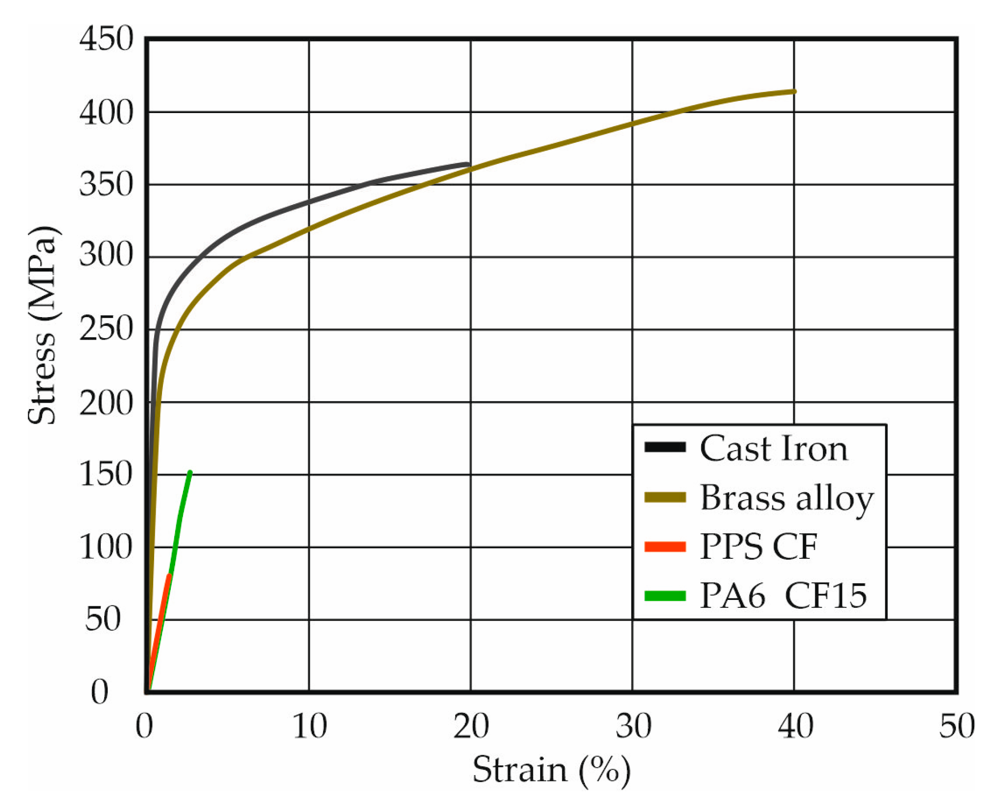
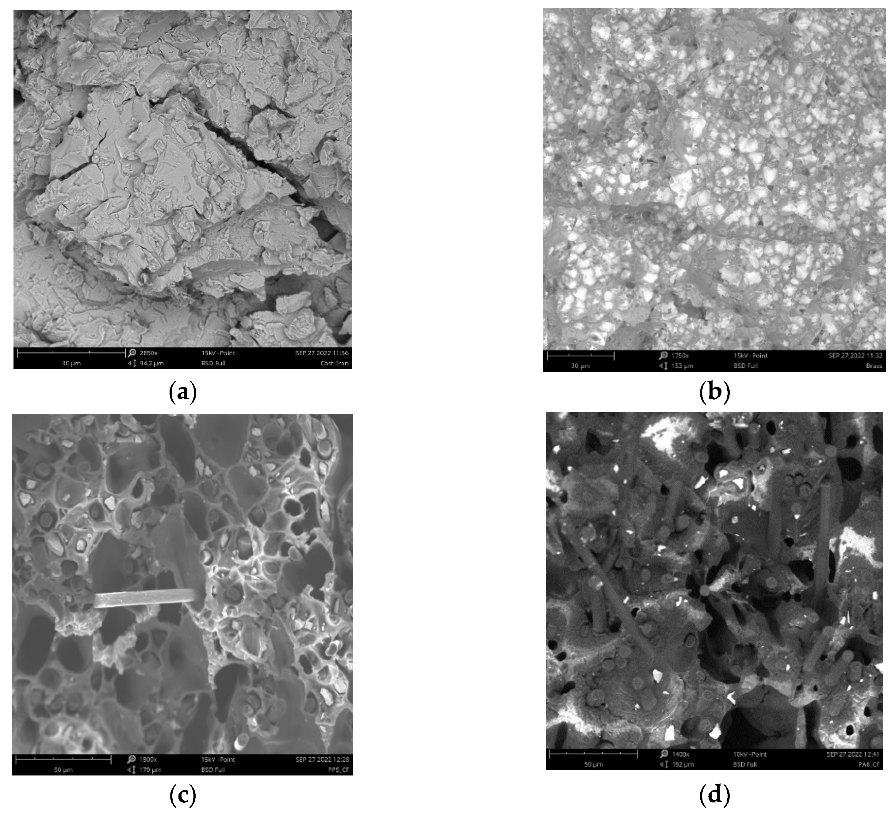
3.1. Mechanical Property and Fracture Morphology
3.2. Computational Fluid Dynamics of an Impeller
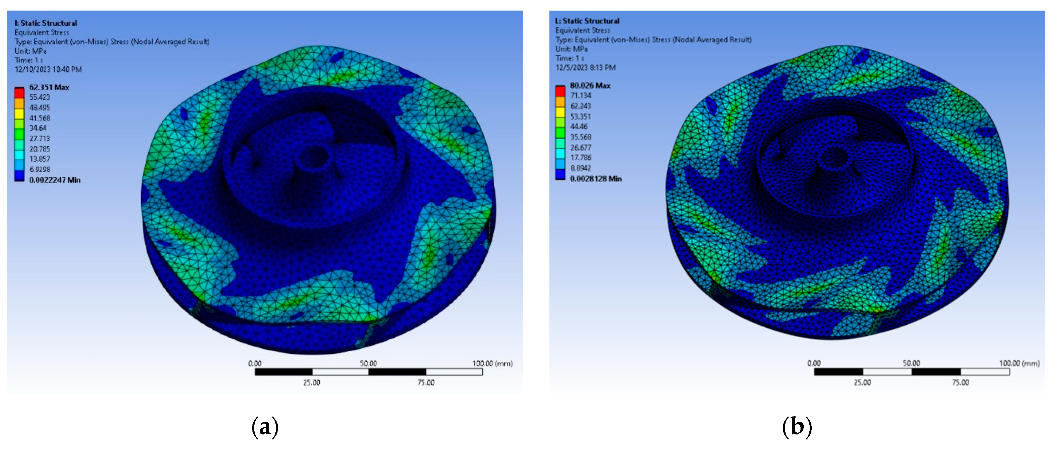
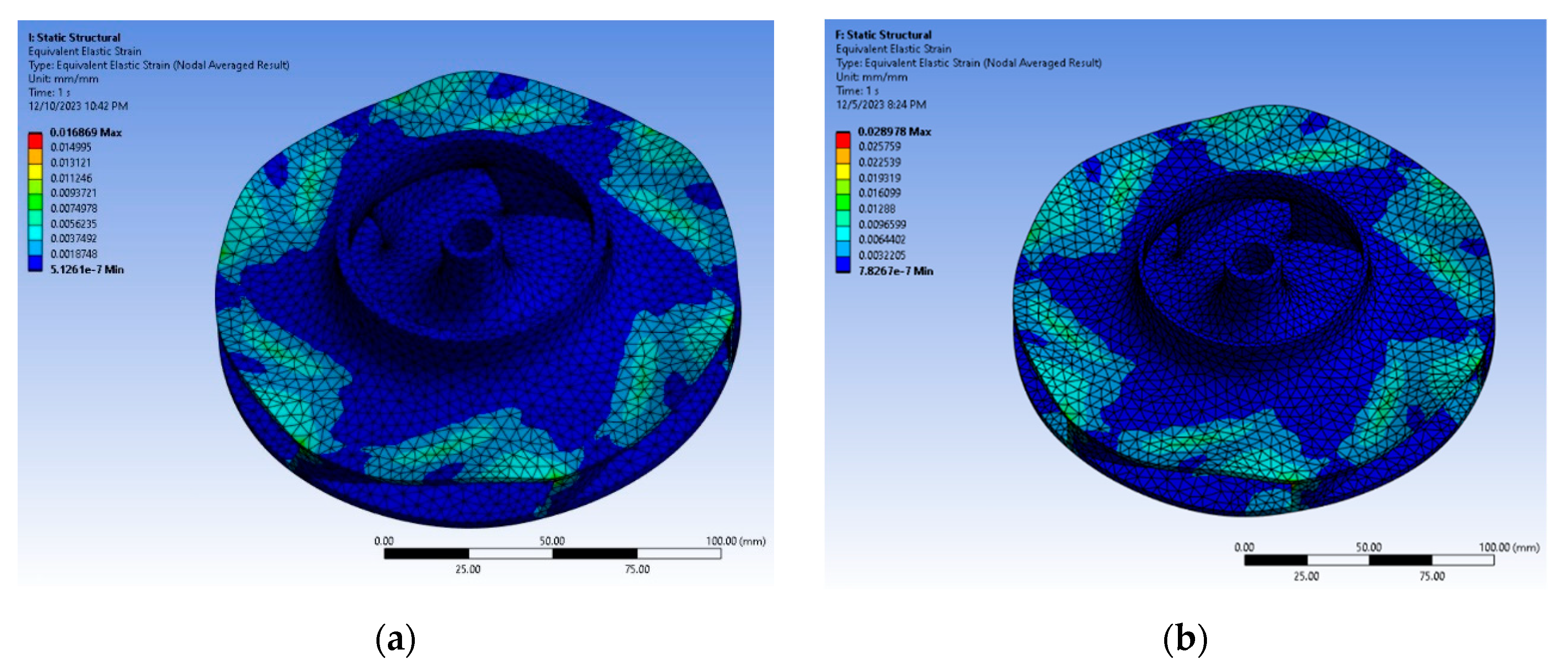
3.3. Impeller Structural Analysis
4. Conclusions
Author Contributions
Funding
Institutional Review Board Statement
Informed Consent Statement
Data Availability Statement
Acknowledgments
Conflicts of Interest
References
- Frazier, W.E. Metal Additive Manufacturing: A Review. J. Mater. Eng. Perform. 2014, 23, 1917–1928. [Google Scholar] [CrossRef]
- Gebisa, A.W.; Lemu, H.G. A case study on topology optimized design for additive manufacturing. IOP Conf. Ser. Mater. Sci. Eng. 2017, 276, 12–26. [Google Scholar] [CrossRef]
- Kladovasilakis, N.; Charalampous, P.; Tsongas, K.; Kostavelis, I.; Tzovaras, D.; Tzetzis, D. Influence of Selective Laser Melting Additive Manufacturing Parameters in Inconel 718 Superalloy. Materials 2022, 15, 1362. [Google Scholar] [CrossRef] [PubMed]
- Kladovasilakis, N.; Charalampous, P.; Tsongas, K.; Kostavelis, I.; Tzetzis, D.; Tzovaras, D. Experimental and Computational Investigation of Lattice Sandwich Structures Constructed by Additive Manufacturing Technologies. J. Manuf. Mater. Process. 2021, 5, 95. [Google Scholar] [CrossRef]
- Koltsakidis, S.; Koidi, V.; Tzimtzimis, M.; Lappas, A.A.; Heracleous, E.; Tzetzis, D. Influence of Binder Concentration in Zeolitic ZSM-5/Bentonite 3D Printed Monoliths Fabricated Through Robocasting for Catalytic Applications. Int. J. Adv. Manuf. Technol. 2023, 126, 259–271. [Google Scholar] [CrossRef]
- Zoumaki, M.; Mansour, M.T.; Tsongas, K.; Tzetzis, D.; Mansour, G. Mechanical Characterization and Finite Element Analysis of Hierarchical Sandwich Structures with PLA 3D-Printed Core and Composite Maize Starch Biodegradable Skins. J. Compos. Sci. Vol. 2022, 6, 118. [Google Scholar] [CrossRef]
- Assael, M.J.; Antoniadis, K.D.; Metaxa, I.; Tzetzis, D. Measurement of the Enhancement of the Thermal Conductivity of an Epoxy-Resin Polymer when Reinforced with Glass Fibres and/or Carbon Multi-Walled Nanotubes. J. Chem. Eng. Data 2009, 54, 2365–2370. [Google Scholar] [CrossRef]
- Tzetzis, D.; Hogg, P.J. Bondline Toughening of Vacuum Infusion Composite Repairs. Compos. Part A Appl. Sci. Manuf. 2006, 37, 1239–1251. [Google Scholar] [CrossRef]
- Joosten, M.W.; Neave, M.B.; Rider, A.N.; Varley, R.J. 3D printed continuous fibre composite repair of sandwich structures. Compos. Struct. 2022, 290, 115518. [Google Scholar] [CrossRef]
- Crump, S.S. Apparatus and Method for Creating Three-Dimensional Objects. U.S. Patent 5,121,329, 1992. [Google Scholar]
- Crump, S.S. Modeling Apparatus for Three-Dimensional Objects. U.S. Patent 5,340,433, 1994. [Google Scholar]
- Kladovasilakis, N.; Tsongas, K.; Tzetzis, D. Mechanical and FEA-Assisted Characterization of Fused Filament Fabricated Triply Periodic Minimal Surface Structures. J. Compos. Sci. 2021, 5, 58. [Google Scholar] [CrossRef]
- Yongnian, Y.; Shengji, L.; Zhang, R.; Feng, L.; Rendong, W.; Qingping, L.; Zhou, X. Rapid Prototyping and Manufacturing Technology: Principle, Representative Technics, Applications, and Development Trends. Tsinghua Sci. Technol. 2009, 14 (Suppl. S1), 1–12. [Google Scholar]
- Gibson, I.; Rosen, D.W.; Stucker, B. Additive Manufacturing Technologies, 1st ed.; Springer: New York, NY, USA, 2010. [Google Scholar] [CrossRef]
- Cella, L. Pump Materials. 22 July 2022. Available online: https://www.pumpindustry.com.au/pump-materials-part-1/ (accessed on 12 February 2024).
- Lee, D.-I.; Lim, H.-C. Erosion-corrosion damages of water-pump impeller. Int. J. Automot. Technol. 2009, 10, 629–634. [Google Scholar] [CrossRef]
- Vazdirvanidis, A.; Pantazopoulos, G.; Rikos, A. Corrosion investigation of stainless-steel water pump components. Eng. Fail. Anal. 2017, 82, 466–473. [Google Scholar] [CrossRef]
- Khalid, Y.A.; Sapuan, S.M. Wear analysis of centrifugal slurry pump impellers. Ind. Lubr. Tribol. 2007, 59, 18–28. [Google Scholar] [CrossRef]
- Sun, J.; Chen, S.; Qu, Y.; Li, J. Review on stress corrosion and corrosion fatigue failure of centrifugal compressor impeller. Chin. J. Mech. Eng. 2015, 28, 217–225. [Google Scholar] [CrossRef]
- Pavlovic, A.; Šljivić, M.; Kraišnik, M.; Ilić, J.; Anic, J. Polymers in additive manufacturing: The case of a water pump impeller. FME Trans. 2017, 45, 354–359. [Google Scholar] [CrossRef]
- Fernández, S.; Jiménez, M.; Porras, J.; Romero, L.; Espinosa, M.M.; Domínguez, M. Additive Manufacturing and Performance of Functional Hydraulic Pump Impellers in Fused Deposition Modelling Technology. J. Mech. Des. 2016, 138, 024501. [Google Scholar] [CrossRef]
- Andres, N.S. Development of Solar-Powered Water Pump with 3D Printed Impeller. Open Eng. 2020, 11, 249–253. [Google Scholar] [CrossRef]
- Kladovasilakis, N.; Kontodina, T.; Charalampous, P.; Kostavelis, I.; Tzetzis, D.; Tzovaras, D. A case study on 3D scanning, digital reparation and rapid metal additive manufacturing of a centrifugal impeller. IOP Conf. Ser. Mater. Sci. Eng. 2021, 1037, 012018. [Google Scholar] [CrossRef]
- Jayawardane, H.; Davies, I.J.; Gamage, J.R.; John, M.; Biswas, W.K. Additive Manufacturing of Recycled Plastics: A ‘Techno-eco-eciency’ Assessment. Int. J. Adv. Manuf. Technol. 2022, 126, 1471–1496. [Google Scholar] [CrossRef]
- Rajenthirakumar, D.; Jagadeesh, K.A. Analysis of interaction between geometry and efficiency of impeller pump using rapid prototyping. Int. J. Adv. Manuf. Technol. 2009, 44, 890–899. [Google Scholar] [CrossRef]
- Selamat, F.E.; Iskandar, W.H.; Izhan, W. Design and Analysis of Centrifugal Pump Impeller for Performance Enhancement. J. Mech. Eng. 2018, 5, 36–53. [Google Scholar]
- Yadav, K.K.; Mendiratta, K.; Gahlot, V. Optimization of the Design of Radial Flow Pump Impeller through CFD Analysis. Int. J. Res. Eng. Technol. 2016, 5, 157–161. [Google Scholar]
- Rajendran, S.; Purushothaman, K. Analysis of a centrifugal pump impeller using ANSYS-CFX. Int. J. Eng. Res. Technol. 2012, 1, 1–6. [Google Scholar]
- Muttalli, R.S.; Agrawal, S.; Warudkar, H. CFD Simulation of Centrifugal Pump Impeller Using ANSYS-CFX. Int. J. Innov. Res. Sci. Eng. Technol. 2014, 3, 15553–15561. [Google Scholar] [CrossRef]
- Adiaconitei, A.; Vintila, I.S.; Mihalache, R.; Paraschiv, A.; Frigioescu, T.; Vladut, M.; Pambaguian, L. A Study on Using the Additive Manufacturing Process for the Development of a Closed Pump Impeller for Mechanically Pumped Fluid Loop Systems. Materials 2021, 14, 967. [Google Scholar] [CrossRef] [PubMed]
- Spectrum FDM Filament PA6-CF15 Technical Specification Data. Available online: https://spectrumfilaments.com/wp-content/uploads/2022/05/en_tds_spectrum_pa6_cf15.pdf (accessed on 10 March 2024).
- BS EN 10002-1:1990; Tensile Testing of Metallic Materials—Method of Test at Ambient Temperature. British Standards Institution: London, UK, 2001.
- TreeD FDM Filament PPS-CF15 Technical Specification Data. Available online: https://treedfilaments.com/datasheets/tech/TDS_PPSCF.pdf (accessed on 10 March 2024).
- Oliver, W.; Pharr, G. An improved technique for determining hardness and elastic modulus using load and displacement sensing indentation experiments. J. Mater. Res. 1992, 7, 1564–1583. [Google Scholar] [CrossRef]
- Tsongas, K.; Tzetzis, D.; Karantzalis, A.E.; Banias, G.; Ahmadkhaniha, D.; Zanella, C.; Matikas, T.E.; Bochtis, D. Microstructural, Surface Topology and Nanomechanical Characterization of Εlectrodeposited Ni-P/SiC Nanocomposite Coatings. Appl. Sci. 2019, 9, 2901. [Google Scholar] [CrossRef]
- Mansour, M.; Tsongas, K.; Tzetzis, D.; Antoniadis, A. Mechanical and Dynamic Behavior of Fused Filament Fabrication 3D Printed Polyethylene Terephthalate Glycol Reinforced with Carbon Fibers. Polym. Plast. Technol. Eng. 2018, 57, 1715–1725. [Google Scholar] [CrossRef]
- Mansour, M.; Tsongas, K.; Tzetzis, D. 3D Printed Hierarchical Honeycombs with Carbon Fiber and Carbon Nanotube Reinforced Acrylonitrile Butadiene Styrene. J. Compos. Sci. 2021, 5, 62. [Google Scholar] [CrossRef]


| Physical Properties | PA6-CF15 | PPS-CF15 |
|---|---|---|
| Heat distortion temperature (HDT) | 200 °C | 220 °C |
| Continuous service temperature | 150 °C | 220 °C |
| Coefficient of thermal expansion | 0.4 × 10⁻⁵/K | 3 × 10⁻⁵/K |
| Linear mold shrinkage | 0.00–0.1% | 0.2–0.5% |
| Water absorption, 23 °C/24 h | <0.3% | <0.05% |
| Specific gravity | 1.25 g/cm3 | 1.49 g/cm3 |
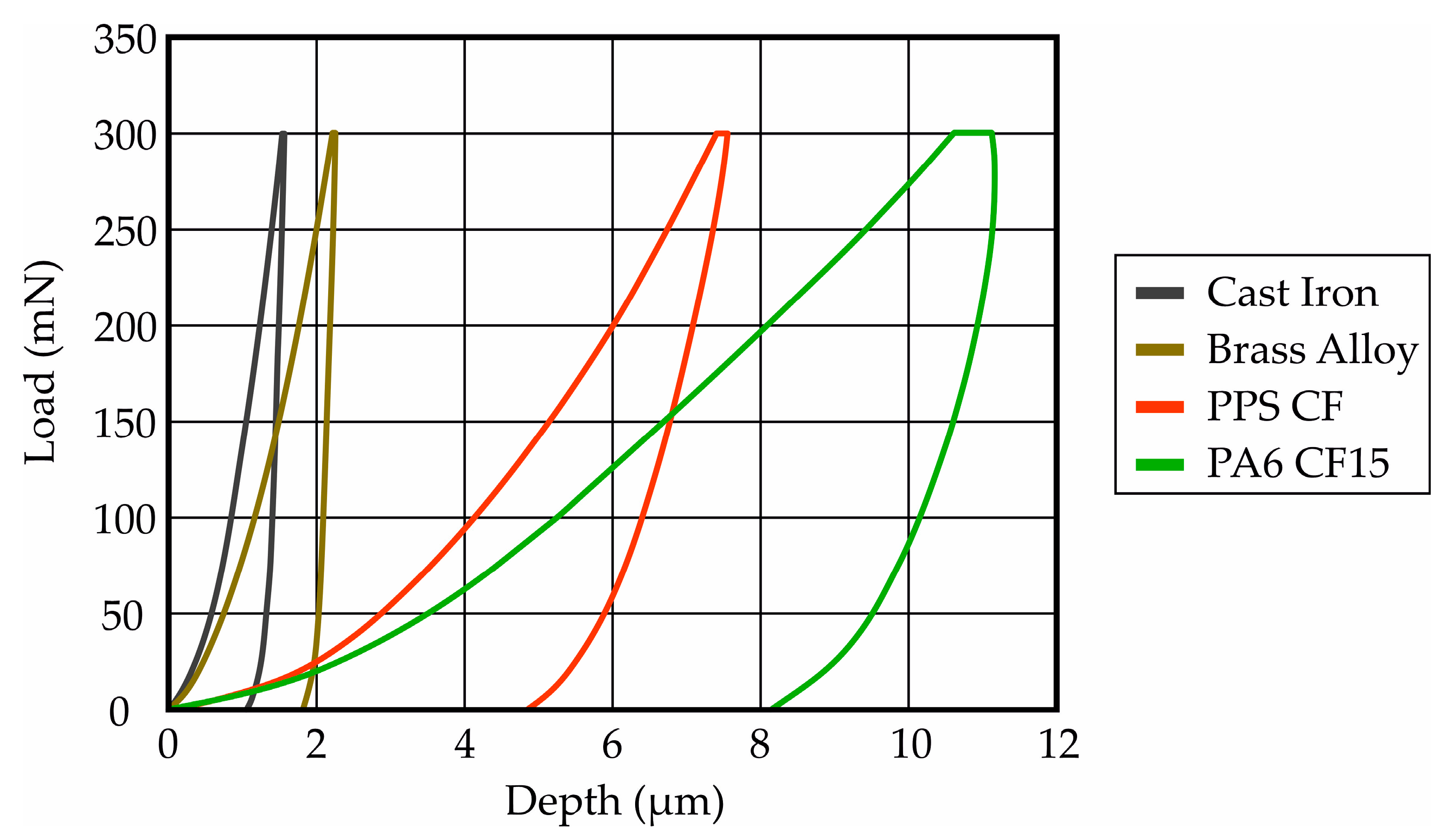
| Material | Tensile Strength (MPa) | Tensile Yield Strength (MPa) | Strain (%) | Modulus of Elasticity (GPa) | Hardness (MPa) |
|---|---|---|---|---|---|
| Cast iron | 314.53 | 235 | 20.225 | 216 | 613.17 |
| Brass | 411.25 | 210 | 40.37 | 108 | 238.33 |
| PA6-CF15 | 150.48 | 140 | 2.19 | 4.57 | 13.72 |
| PPS-CF15 | 79.8 | 70 | 1.32 | 5.13 | 26.16 |
| Input Parameter | Symbol | Value |
|---|---|---|
| Volume flow rate | Q [m3/h] | 25 |
| Head rise | H [m] | 17 |
| Power | P [kW] | 1.492 |
| Rotational speed | N [rpm] | 2900 |
| Inlet flow angle | θ1 [degree] | 90 |
| Hydraulic efficiency | ηH | 0.87 |
| Volumetric efficiency | ηV | 0.97 |
| Mechanical efficiency | ηm | 0.95 |
| Pump efficiency | ηρ | 0.8 |
| Assumptions | Symbol | Value |
|---|---|---|
| Shaft min diameter safety factor | 1.2 | |
| Hub to shaft diameter ratio | 1.5 | |
| Hub inlet draft angle | β1 [degree] | 30° |
| Blade angle at exit | β2 [degree] | 22.5° |
| Impeller Nominal Power (kW) | Inlet Diameter (mm) | Outlet Diameter (mm) | Blade Height (mm) | Mass Flow (m3/h) | Head (m) | Number of Blades |
|---|---|---|---|---|---|---|
| 4.1 kW | 73 | 183 | 10.5 | 40 | 30 | 6 |
| 5.59 kW | 77 | 175 | 11.5 | 42 | 35 | 6 |
| 7.46 kW | 84.5 | 177 | 13 | 55 | 40 | 6 |
| 9.32 kW | 88 | 193 | 13.5 | 55 | 48 | 6 |
| Calculated Power (kW) | Mass Flow (m3/h) | Calculated Head (m) | Total Efficiency (%) | Number of Elements |
|---|---|---|---|---|
| 4.089 | 40 | 36.32 | 95.42 | 203,310 |
| 5.528 | 42 | 46.62 | 93.68 | 219,294 |
| 7.348 | 55 | 47.53 | 94.66 | 210,654 |
| 9.109 | 55 | 58.07 | 94.2 | 408,986 |
Disclaimer/Publisher’s Note: The statements, opinions and data contained in all publications are solely those of the individual author(s) and contributor(s) and not of MDPI and/or the editor(s). MDPI and/or the editor(s) disclaim responsibility for any injury to people or property resulting from any ideas, methods, instructions or products referred to in the content. |
© 2024 by the authors. Licensee MDPI, Basel, Switzerland. This article is an open access article distributed under the terms and conditions of the Creative Commons Attribution (CC BY) license (https://creativecommons.org/licenses/by/4.0/).
Share and Cite
Mansour, G.; Papageorgiou, V.; Tzetzis, D. Carbon Fiber Polymer Reinforced 3D Printed Composites for Centrifugal Pump Impeller Manufacturing. Technologies 2024, 12, 48. https://doi.org/10.3390/technologies12040048
Mansour G, Papageorgiou V, Tzetzis D. Carbon Fiber Polymer Reinforced 3D Printed Composites for Centrifugal Pump Impeller Manufacturing. Technologies. 2024; 12(4):48. https://doi.org/10.3390/technologies12040048
Chicago/Turabian StyleMansour, Gabriel, Vasileios Papageorgiou, and Dimitrios Tzetzis. 2024. "Carbon Fiber Polymer Reinforced 3D Printed Composites for Centrifugal Pump Impeller Manufacturing" Technologies 12, no. 4: 48. https://doi.org/10.3390/technologies12040048
APA StyleMansour, G., Papageorgiou, V., & Tzetzis, D. (2024). Carbon Fiber Polymer Reinforced 3D Printed Composites for Centrifugal Pump Impeller Manufacturing. Technologies, 12(4), 48. https://doi.org/10.3390/technologies12040048