1. Introduction
Optically trapped neutral atoms have proven to be an excellent experimental platform in the pursuit of understanding the physical reality of quantum mechanics. Fundamental research of atom-light interaction at the individual atoms level has consolidated our knowledge of microscopic systems and improved the level of control of such systems tremendously. This has led to the idea of using the knowledge and control tools to develop new technologies based on quantum physics as part of the second quantum revolution.
One of these important future quantum based technologies is quantum information processing. According to DiVincenzo criteria, a physical realization of quantum information processing requires a string of qubits that can interact with each other but have long relevant coherence times [
1,
2]. Individual neutral atoms have presented themselves as candidates for qubits [
3,
4,
5,
6]. An array of optical microtraps with each site storing a single atom [
7,
8,
9,
10] is a promising working arrangement to fulfill the DiVicenzo criteria. The probability of having an array of
N sites all filled with an atom simultaneously scales with the single atom preparation efficiency to the power of
N. Therefore high efficiency loading of single neutral atoms is an important step to realize a scalable quantum information processing device [
7,
11,
12,
13]. Additionally, trapped single cold atoms in separate traps has minimal perturbation due to interaction with the environment, which is utilized in quantum metrology in such apparatus as a 3D optical lattice clock [
14,
15].
Over the past few decades, several important techniques have been developed to spatially confine neutral atoms by using optical traps and to control the motion of atoms [
16,
17,
18,
19]. Of these, Far-Off Resonance Traps (FORT) [
19] provide conservative potentials for the atoms and they can be dynamically reconfigured [
12,
20]. This makes FORTs an attractive tool to trap single neutral atoms. Furthermore, atoms in FORTs have long coherence times and both the long and short range atomic interactions can be controlled [
3,
21,
22,
23]. A few different approaches have been developed to achieve efficient preparation of single neutral atoms in FORTs. These include the redistribution of individual atoms into arrays of microtraps by atom-sorting [
24], isolation of single atoms in microtraps by using the superfluid to Mott-insulator transition from a Bose-Einstein condensate [
11,
25,
26] or using Pauli’s exclusion principle [
23], and using the Rydberg blockade mechanism [
27], Penning ionization [
28], or repulsive light-assisted collisions [
29,
30,
31] to ensure that the trap is not occupied by more than one atom.
Using light-assisted collisions to prepare single neutral atoms in FORTs have gained considerable interests in recent years due to its relative simplicity and speed. Sub-poissonian loading was first observed in optical lattices [
32] and in tight optical tweezers [
33,
34] where the collisional blockade takes effect. The preparation efficiencies were initially reported to be about
. Near-deterministic single atoms preparation in a FORT using repulsive light-assisted collisions were reported in [
29,
30], with efficiency of
. With similar methods, the preparation efficiency in collisional blockade loading can be enhanced to about
[
35]. Recently, repulsive light-assisted collisions have been employed to load single atoms in multiple traps with efficiency of up to
[
31].
The main subject of this review is on the advances of experimental methods to near-deterministically prepare a single neutral atom in an optical microtrap by using light-assisted collisions. Investigation of the dynamics of two atoms under the influence of near resonant light inside an optical microtrap reveals the physics behind the method [
36]. This kind of light-assisted two-atom collision experiments allow us to discriminate and quantify different two-atom loss channels, which could be of fundamental interest [
37,
38].
In
Section 2, we will review the concepts of light-assisted collisions between two atoms.
Section 3 describes the experimental apparatus used in the works of this review.
Section 4 describes the dynamics between two atoms in a FORT under the presence of near resonant light.
Section 5 presents the method to achieve high preparation efficiency of single atom in a FORT using repulsive light-assisted collisions.
Section 6 presents how the method can be extended to efficient collisional blockade loading of single atom into a tight microtrap.
Section 7 provides some discussion, future directions and summary.
2. Light-Assisted Collisions Between Two Atoms
The subject of collisions between two atoms assisted by near resonant light occupies an important position in a wide range of research in atomic, molecular and optical physics. The mechanisms and effects of binary collisions between cold atoms have been widely studied since the advent of laser cooling and trapping of atomic gasses. The model of light-assisted collisions that we will review in this section is based on the semiclassical approach described in [
39,
40,
41].
The basic features of collisions between two Rubidium-85 (
Rb) atoms can be described schematically with
Figure 1.
is the ground state interaction potential as a function of internuclear separation
R and its long range asymptote is
, where
is a constant [
42]. The atom-atom interaction is negligible when
R is large and here the ground state is just two atoms each in their ground state, represented by
. The first excited molecular state, at large
R, is denoted by
where one of the atoms is in its ground state and the other atom is in its excited state. This first excited molecular potential has a long range asymptote of
, where
is the atomic excitation energy and
is a constant arising from the resonant dipole interaction [
42,
43]. At this excited state the atoms approach along the
potential, that can be either attractive or repulsive depending on the relative phase of the interacting dipoles.
Figure 1.
Light assisted collisions model: interaction potentials as a function of internuclear separation
R. Red arrows represent the process of excitation of two ground state atoms to an attractive potential (red curve). Blue arrows represent the process of excitation of the atoms to a repulsive potential (blue curve). Figure adapted from [
44].
As two atoms approach each other in a collision, the transition frequency changes. The Condon point is the internuclear separation where the atom pair is on resonance with the light field of frequency , i.e., . For near resonant light fields (relative to the atomic transition), the excited state potential can be approximated by the asymptote. In addition, the ground state potential is approximated to be independent of R. This gives a Condon point of , where is the detuning of the light field from the free atom resonance. At , two ground state atoms may absorb a photon and get transferred to the excited state. If the light is red-detuned, then the atoms will be excited to the attractive potential. If the light is blue-detuned, then the atoms will be excited to the repulsive potential.
To understand the outcomes of the collisions, we use the Landau-Zener (LZ) formalism for avoided crossings in the dressed state picture [
41] to quantify the probability that the atoms get transferred to the excited states when the internuclear separation crosses
. The dressed state picture for the collisional processes are shown in
Figure 2 and
Figure 3. The asymptotic states are the atom-field states, denoted by
(
n is the photon number in the light field) and
. If there is no optical coupling, the dressed states will cross each other at
. The coupling by the light field forms a Landau-Zener avoided crossing at
. As the internuclear separation crosses
in a collision, the atom pair may either undergo adiabatic following, where they move through the coupling region adiabatically, or undergo a LZ transition. The probability that the two colliding atoms undergo a LZ transition is given by
with
v being the relative radial speed of the atoms and Ω being the on-resonance (with molecular transitions) Rabi frequency proportional to the light intensity [
41]. The probability of adiabatic following is then
.
In a collisional process involving the repulsive excited state potential, which is induced by a blue-detuned light field, the atoms cross
twice: first when they are approaching each other and again when they are separating from each other. The collision may be an elastic process where the atoms enter and exit the collision in the
state and there is no net gain in kinetic energy. This can happen when the colliding atoms undergo adiabatic followings or LZ transitions both times at
(shown as paths ER 1 and ER 2 in
Figure 2A). Alternatively, the collision may be an inelastic process where the atoms enter the collision in the
state but exit in the
state. This happens when the atoms first undergo an LZ transition and then an adiabatic following, or vice versa (shown as paths IR 1 and IR 2 in
Figure 2B). The probability for this inelastic collision to occur is
. If no spontaneous emission takes place during collision, then the energy gained by the atoms in an inelastic collision is given by
, since
is the energy difference between the states at large
R [
41,
45].
Figure 2.
Dressed state picture for a repulsive collisional process showing an avoided crossing at : (A) Possible paths for elastic collisions. Path ER 1 is the case where the atoms undergo adiabatic following both times at . Path ER 2 is the case where the atoms undergo LZ transition both times at . (B) Possible paths for inelastic collisions (IR 1 and IR 2).
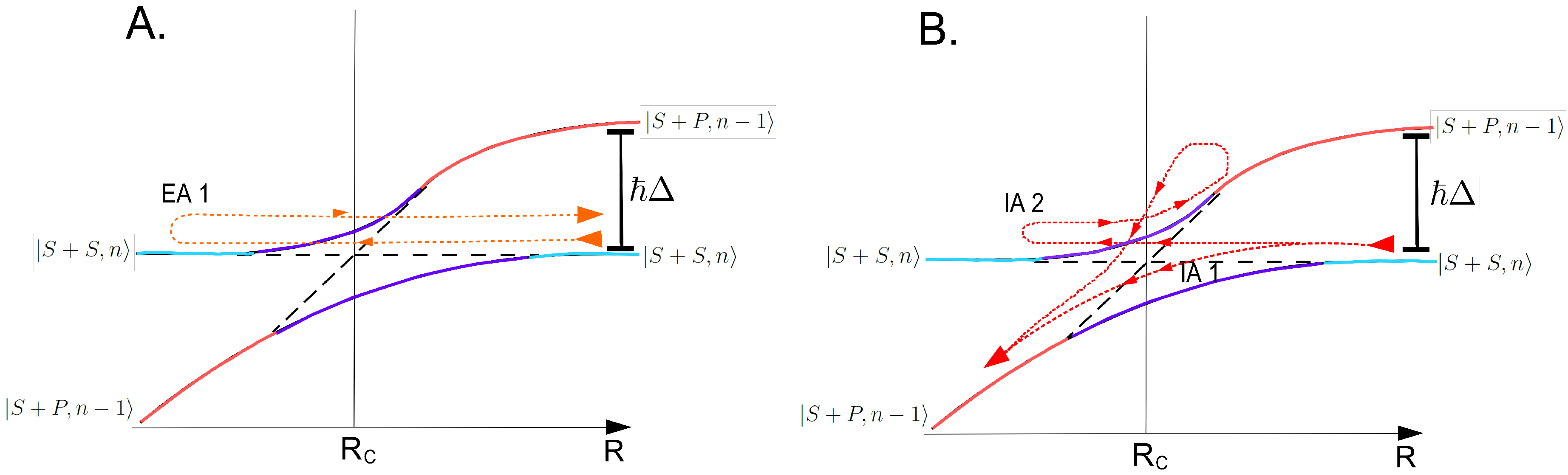
In a collisional process involving the attractive excited state potential, which is induced by a red-detuned light field, elastic (paths EA 1 in
Figure 3A) and inelastic collisions can happen. There are two types of inelastic collisions. The first one is shown as path IA 1 in
Figure 3B: the atoms undergo an adiabatic following through the coupling region at the first instance and exit the collision via the
state. The second is shown as path IA 2 in
Figure 3B: the atoms initially undergo an LZ transition and then adiabatically follow their state that becomes attractive. The atoms will therefore return to
for a third time where they can undergo an LZ transition to the other dressed state. If an LZ transition does not occur at this point, then the process may repeat. The probability for inelastic collision to occur can be approximated by [
41]:
. In an inelastic collision, the atoms accelerate towards each other and roll down the excited state potential curve before spontaneous emission to the ground state happens at a position
. This results in the atoms gaining kinetic energy
given by the difference between the attractive excited state interaction energy at
and at
, the internuclear separation where the spontaneous emission takes place (see
Figure 1).
Figure 3.
Dressed state picture for an attractive collisional process showing an avoided crossing at : (A) Possible paths for elastic collisions (EA 1). (B) Possible paths for inelastic collisions (IA 1 and IA 2).
Figure 3.
Dressed state picture for an attractive collisional process showing an avoided crossing at : (A) Possible paths for elastic collisions (EA 1). (B) Possible paths for inelastic collisions (IA 1 and IA 2).
From an experimental point of view, we can tune the laser frequency. By using blue-detuned light to induce collisions, we have a certain level of control that limits the energy released in each inelastic collision. This is in stark contrast to the case of collisions induced by red-detuned light, where the amount of energy released in an inelastic collision is bounded by the excited molecular potential, which is beyond our control.
4. Dynamics of Two Atoms Undergoing Light-Assisted Collisions in a FORT
In the field of optical trapping of atoms, it has been known that light-assisted collisions between atoms can lead to trap loss. In an inelastic collision, the kinetic energy gained by an atom can exceed the potential of the trap, causing the atom to escape from the trap. Depending on the dynamics of the atoms inside the trap, the collisional trap loss events can be either the loss of both colliding atoms ( loss) or the loss of only one of the two colliding atoms ( loss). Another trap loss is the one-body loss that is due to the finite lifetime of an atom in the trap, which for example, is dependent on the atomic equilibrium temperature and the vacuum condition.
For efficient preparation of single atom in a FORT using light-assisted collisions, it is crucial that
loss dominates over
loss [
30]. In this section, we study the atoms dynamics leading to the different loss channels and how it can be influenced by experimental parameters. We do this by observing the outcomes of the ideal collision experiments that starts with exactly two atoms. This allows us to discriminate between
loss and
loss events, and thereby observe how their relative rates depend on the relevant parameters. This information is usually not accessible in experiments conducted using large samples, where the trap losses typically are described by ensemble average parameters.
Through the two-atom experiments, we can better understand the mechanisms of the and loss channels due to light-assisted collisions in the presence of laser cooling. In particular, we can identify the roles played by red-detuned collisional light, blue-detuned collisional light and the effect of laser cooling on the rates of the loss channels. Understanding how the loss channel rates depend on various light parameters forms the grounds that will allow us to implement an efficient method to prepare single atoms in a FORT in the subsequent sections.
4.1. Light-Assisted Collisions Between Two Atoms in a FORT
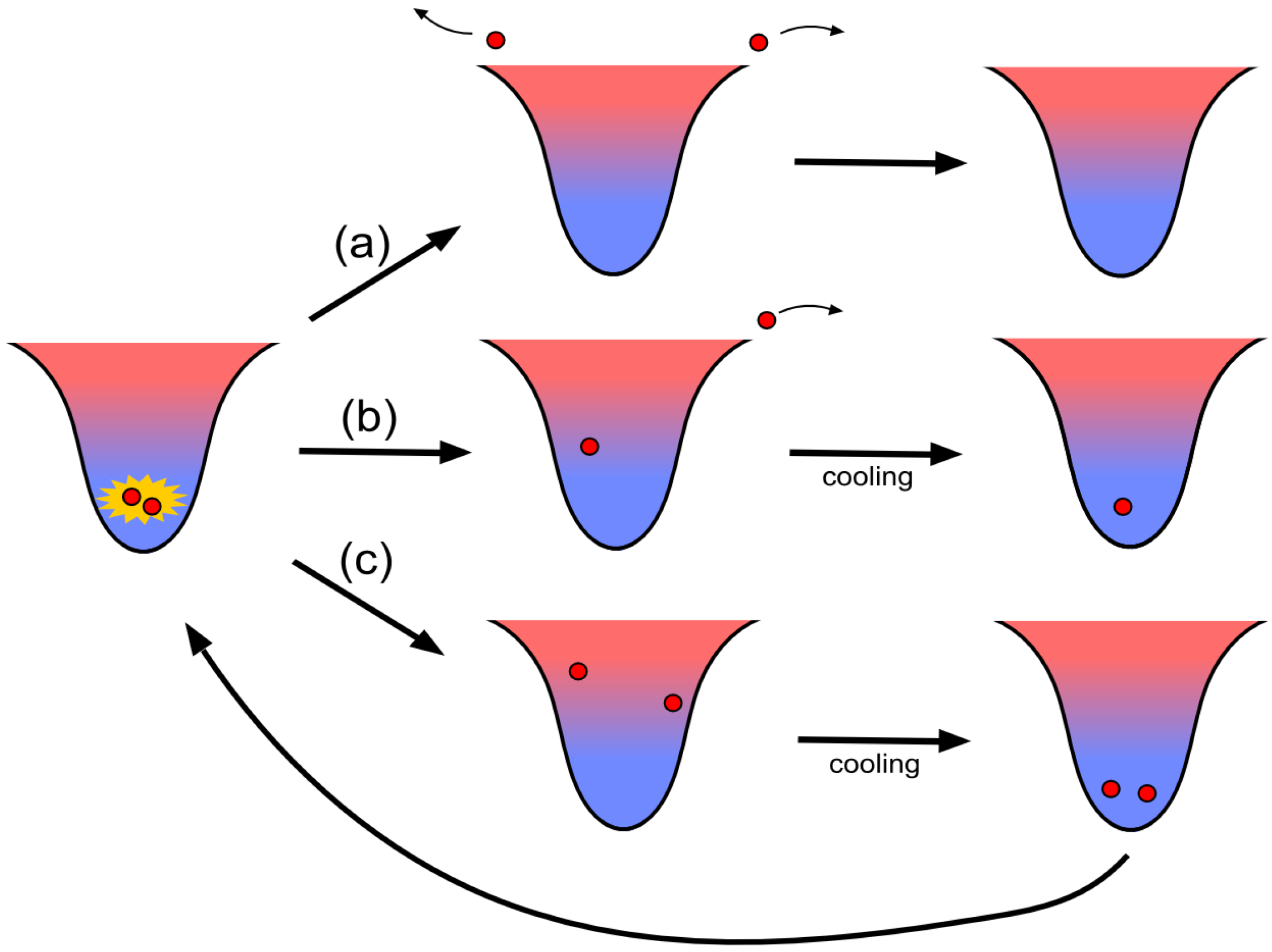
Figure 5 shows the various outcomes of light-assisted collision between two atoms in a FORT, combined with the effect of in-trap laser cooling. Path (a) shows two colliding atoms escaping (
loss), ending with no atoms left inside the trap. For this channel to be present, the collision must release sufficient energy such that the total energy of the atoms after the collision,
, is enough for both of the two atoms to escape the trap potential. This can arise when high energy is released upon collision or/and when the atoms have high thermal energies prior to the collision.
Figure 5.
Light-assisted collisions between two atoms with laser cooling. Path (a) shows two colliding atoms escaping ( loss), leaving no atoms inside the trap. Path (b) shows one of the two colliding atoms escaping ( loss), leaving one atom inside the trap. Path (c) shows neither of the two colliding atoms escaping. Laser cooling removes the energy of the atoms.
Path (b) shows one of the two colliding atoms escaping ( loss), leaving one atom inside the trap. This happens when the two colliding atoms have unequal energies after the collision such that one of the two atoms has enough energy to escape the trap potential, while the other atom stays in the trap. Therefore it does not require as high as path (a). However, the atoms should share the energy released in the collision unevenly, which may happen if the thermal energy of the two atoms give them sufficient centre of mass momentum prior to the collision.
Path (c) shows neither of the two colliding atoms escaping. This happens when low energy is released in a collision such that neither of the atoms has sufficient energy to escape the trap potential. There are two scenarios that may lead to this. Trivially if is insufficient for any atoms to escape then no atom will be lost. But in the situation where is sufficient for one atom to escape but insufficient for both to escape, the atoms may share the released energy more or less evenly, leading to no atom escaping. The laser cooling taking place inside the trap can then remove the energy released in the collision, returning the atoms to the condition prior to the collision. This can prevent the atoms from having high energies before the next collision, which can increase the chance of loss. We will discuss the role of laser cooling later in this section.
4.2. Two-Atom Light-Assisted Collisions Induced by Red-Detuned Light
In this subsection, we want to investigate the dynamics of just two atoms in a FORT, undergoing light-assisted collisions induced by red-detuned light. Typically, cold atoms are loaded into a FORT from a MOT, which utilizes red-detuned light beams. Studies of individual collisional loss events in a MOT with high gradient magnetic field has shown that about 10 percent of collisional loss events are
loss [
48].
As mentioned in
Section 2, inelastic collisions induced by red-detuned light can release a kinetic energy
given by the difference between the attractive excited state potential energy at
and
. The probability densities of the released energy
for different red detunings calculated with methods described in [
36] are shown in
Figure 6. For small detunings, the gentle slope of the attractive excited potential at
makes it more likely that spontaneous emission has occurred before the atom pair managed to gather any significant relative acceleration. The energy released in these collisions might not be large enough to always cause
loss. By observing individual loss events, depending on the light parameters used, we see that the
loss channel is indeed also present in red-detuned collisions.
Figure 6.
The probability densities of the released energy
for head-on collisions induced with light with red detunings of 45, 75 and 105 MHz. The probability of a high energy release are generally small. Figure adapted from [
36].
Figure 6.
The probability densities of the released energy
for head-on collisions induced with light with red detunings of 45, 75 and 105 MHz. The probability of a high energy release are generally small. Figure adapted from [
36].
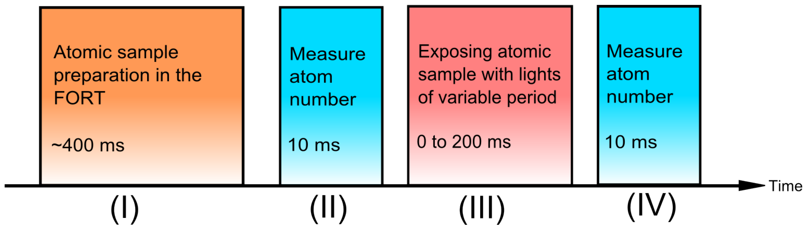
We experimentally prepare two atoms inside the FORT and observe the evolution of the trap population under the influence of near resonant lights. The experimental procedure is illustrated in
Figure 7: We prepare a low number of atoms inside the FORT and determine the number of atoms using methods described in [
46,
47]. We select those realizations with only two atoms inside the trap. We then expose the atoms with near resonant light beams for a variable period and again determine the number of atoms remaining in the trap.
Figure 7.
Experimental procedure to observe the dynamics of two atoms inside a FORT under the influence of near resonant lights: (II) Verify that there are two atoms in the trap initially by fluorescence imaging. (III) Expose the atoms with near resonant light beams (Six D2 cooling beams and a D1 collision beam) with variable duration . (IV) Measure the remaining number of atoms.
We use a
MHz FORT formed by focussing a
nm laser to a spotsize of
μm. The two atoms are exposed with a collision beam that is red-detuned (negative Δ) from the
to
transition at the centre of the FORT to induce the collisions. At the same time, we apply the six cooling beams (the MOT beams) that are
MHz red-detuned from the
to
transition at the centre of the FORT. The experimental results for each exposure time
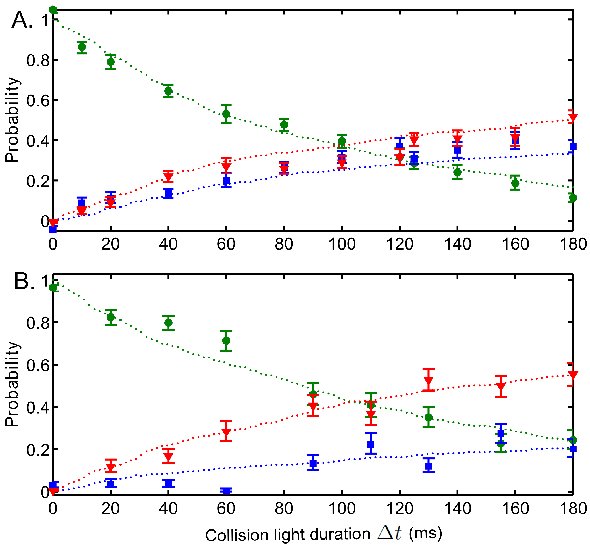
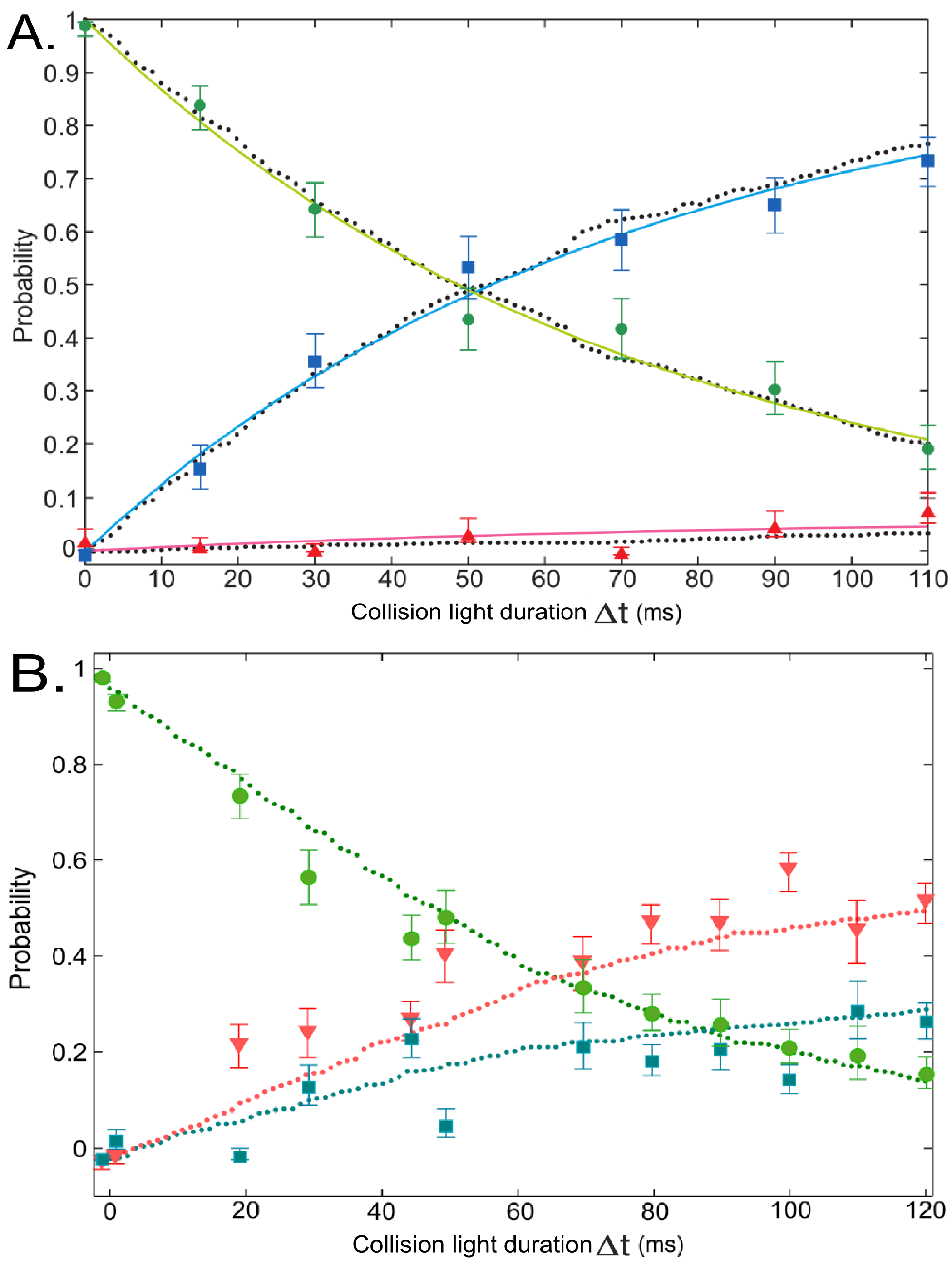
are presented as the probabilities of two, one or zero atoms remaining in the trap after averaging over 180 repetitions of the experimental sequence (with two atoms in the trap initially). This gives us the decay rate of 2 atoms and growth rates of 0 and 1 atom, as shown in
Figure 8, with cooling beam intensities of 11 W/m
for (A) and 19 W/m
for (B).
Figure 8.
Two-atom evolution when exposed to red-detuned light as a function of
. Light parameters: The collision beam is 45 MHz red-detuned from the
to
transition at the centre of the FORT. Figures (
A) and (
B) have cooling beams intensities of 11 W/m
and 19 W/m
respectively. The probabilities of two, one and zero atoms remaining in the trap are indicated by green circles, blue squares and red triangles respectively. The dotted lines are the simulated plots. Error bars represent a statistical confidence of
. Figure adapted from [
36].
The results show that there is a non-zero probability of
loss events when the atoms undergo light-assisted collisions induced by the red-detuned cooling light. There is a broad range of intermediate
s that can lead to a
loss. A high
collision, which has low probability (see
Figure 6), leads to a
loss. However, most of the collisions lead to low energy releases where none of the atoms escape the trap. The atoms may therefore go through a number of collisions until there is one that can lead to
loss or
loss.
With only two atoms, we can simulate the dynamics of the atom pair inside the FORT numerically and compare it with our experimental results. The simulated results are shown as the dotted lines in
Figure 8. In this simulation, which is described in detail in [
36], the main ingredients are: (1) selection of two atoms according to a Maxwell-Boltzmann distribution with measured initial temperature of
K ; (2) calculation of classical trajectories of two atoms inside the Gaussian potential FORT with the effect of laser cooling simulated by a Doppler cooling model; and (3) calculation of the probability of two atoms undergoing an inelastic collision
when their internuclear separation is
using the LZ formalism (described in section 1), which is used to decide if a collision has happened. To determine whether any atoms are lost from the trap, when a collision happens, we generate the energy release probability distribution (similar to
Figure 6), which is dependent on the collisional impact parameters. We then pick the released energy
randomly based on this probability distribution. The simulated results shows good agreement with the experiments, confirming our physical description of the process.
Figure 9 shows the simulated evolution of energies of the atoms in the trap, where we can see the difference between
loss and
loss.
Figure 9.
Simulated evolution of individual and the combined energies of the atom pair: (
A) is the case of
loss and (
B) is the case of
loss. The dashed lines indicate when inelastic collisions occurred. In between the collisions, the energies of the atoms are lowered due to the laser cooling effect. Figure adapted from [
36].
We found empirically that the cooling beams provide some laser cooling on the atoms in the deep FORT. Higher cooling beam intensity yielded faster cooling rate and generally lower equilibrium temperatures. Thus laser cooling plays an important role in the dynamics of the atoms, with different cooling beam intensities giving different probabilities for collisions leading to
loss or
loss (as shown in
Figure 8A,B.) Higher cooling beam intensities generally provide more efficient cooling to lower the
. This increases the required
and the atoms are more likely to have less centre of mass momentum before the next collision, hence reducing the probability of
loss.
Scanning the collision beam detuning Δ in the range of MHz MHz shows that loss events are more likely for smaller detunings while loss events dominate at larger detunings. For larger Δ, the atoms get transferred to the excited molecular state at smaller where the potential gradient is steeper, this leads to large being released in the collision.
The dominance of the
loss channel explains why past experiments such as [
32,
33] have about
chance in ending with one atom in the trap, depending on whether the number of atoms loaded is even or odd. In order to significantly improve the single atom loading efficiencies, the
loss channel must dominate over the
loss channel.
4.3. Two-Atom Light-Assisted Collisions Induced by Blue-Detuned Light
We now study the dynamics of two atoms that undergo light-assisted collisions induced by blue-detuned light. In particular, we want to demonstrate that the
loss can be implemented effectively while suppressing the
loss by using a combination of a blue-detuned beam and in-trap laser cooling. Recall that the maximal energy gained by the atoms in a repulsive inelastic collision induced by blue-detuned light is given by
, so by using blue-detuned light to induce the collisions, we can limit the energy released by the atoms, such that we give finite probability to
loss (path (b) in
Figure 5) while eliminating
loss (path (a) in
Figure 5). For cases where the collision did not cause any trap losses (path (c) in
Figure 5), the energy released is removed by the laser cooling and the atoms are returned to the initial condition. The process can thus repeat until
loss happens and one atom remains in the trap.
The process described can be achieved by the following: firstly, we want the trap loss to happen only from light-assisted collisions induced by a blue-detuned light with Δ in the right range. Trap loss caused by other light sources (e.g., red-detuned light) and trap loss mechanisms that are not due to collisions between the trapped atoms (e.g., one-body loss) have to be eliminated. Before a collision, the atoms must be in an internal ground state that has a transition such that Δ is in the desired range.
Secondly, we want the two colliding atoms to have unequal energies after the collision such that one of the two atoms has enough energy to escape the trap potential, while the other atom stays in the trap. For this to happen, the thermal energy of the two atoms must be large enough such that they can have sufficient centre of mass momentum prior to the collision. However, the thermal energy of the atoms cannot be too high prior to the collision to avoid loss and one-body loss.
We conduct the experiment with a sequence similar to that is described in the last subsection (shown as
Figure 7), except that in stage (III), the collision beam is now blue-detuned (positive Δ) from the
to
transition at the centre of the FORT and has 11
μW in power. The cooling beams have power of
mW per beam and are
MHz red-detuned from the
to
transition at the centre of the FORT. The probabilities of two, one or zero atoms remaining in the trap are shown in
Figure 10, with
MHz for A and
MHz for B.
The two-atom decay time is 70 ms for
Figure 10A and we can see that the
loss is the dominant trap loss channel, where its probability is
of all the collisional trap loss events. Here the
loss channel is favoured by choosing the proper blue-detuned Δ to suppress
loss by limiting the kinetic energies that can be gained by the atoms in an inelastic collision. Almost all of the collisions happen in the
ground state such that
MHz is in the right range to induce the blue-detuned light-assisted collisions. Large Δ can cause significant
loss due to the high energy released upon collisions. This can be seen from
Figure 10B, where
MHz leads to significant
loss.
Any build up of atomic population in the ground state due to off-resonant spontaneous Raman scattering will cause Δ to be off from the right range by the ground state hyperfine splitting. This is prevented by effective optical pumping of the atoms back into the ground state, provided by the six cooling beams. As mentioned before, the equilibrium temperature has to be such that the thermal energy of the two atoms is sufficient for them to share the released energy unevenly but insufficient to cause one-body and loss. Recall that the cooling rate and equilibrium temperature depend on the cooling beam intensity, so this provides a parameter that can be used to optimize loss. Pumping the atoms into the ground state renders the cooling beams to be about 3 GHz off-resonant, thereby suppresing the rate of light-assisted collisions induced by the cooling beams. The two-atom decay timescale due the cooling beams is 4 s, so while loss can be induced, it is negligible in short timescales.
Figure 10.
Two-atom evolution when exposed to blue-detuned light as a function of
: (
A) The collision beam is 85 MHz blue-detuned from the
to
transition at the centre of the FORT. (
B) Other parameters remained the same but the collision beam is 185 MHz blue-detuned. Green circles, blue squares and red triangles are the probabilities of the experiment ending with two, one and zero atoms respectively. The dotted lines are the simulated plots. Error bars represent a statistical confidence of
. Figure adapted from [
44].
The simulated results in
Figure 10 is obtained with simulation similar to that of
Figure 8. However, for the blue-detuned collisions case here, the calculation of the probability of two atoms undergoing an inelastic collision at
is based on
, with collisional energy released given by
. This calculation is to determine whether any collisional trap losses can happen. Note here that in the simulation we adjusted the Ω in
so that the two-atom decay time of the simulation agrees with the experiment. The Ω in the simulation is within a factor of two of the expected Ω based on the beam parameters. The Ω of the simulated results in
Figure 10A,B matched each other within
. The simulated results are consistent with the experimental data.
6. Repulsive Light-Assisted Collisions in Collisional Blockade Preparation of Single Atoms
We now extend the methods of using blue-detuned collision beam to induce the loss into the collisional blockade regime. The basic ideas and the physics behind the preparation methods here are similar to those in the last section (not in collisional blockade regime). However, as we shall see in this section, there are additional challenges and restrictions related to the implemention of the methods in the collisional blockade regime.
The high efficiency of single atom preparation outlined in the last section builds on the fact that an initial sample of about 20 atoms on average can be loaded from the MOT into the FORT during the sample preparation stage. This average initial sample size is large enough to ensure that the probability of starting the isolation stage without any atoms in the FORT is effectively eliminated. A finite probability of having no atoms prior to the isolation stage will naturally translate to lower efficiency of the method. As the trap volume of a FORT gets smaller, it becomes increasingly prohibitive to load high number atomic samples directly from a MOT into a FORT since the tightness of the trap along with the light-assisted collisions induced by the red-detuned MOT light can cause rapid trap loss. This is because of the high atomic density increases the probability of the atoms reaching the Condon point and thus increasing the rate of light-assisted collisions. We denote the regime where the efficiency of the method in the last section is restricted by the volume of the FORT as the “tight microtrap regime” [
35].
The collisional blockade is the extreme manifestation of the tight microtrap regime [
34]. The collisional blockade mechanism prevents the tight microtrap from being occupied by more than one atom at a time since rapid trap loss happens as soon as a second atom enters the trap. The rapid trap loss is a result of the small trap volume and light-assisted collisions induced by the the red-detuned MOT light, often causing
loss. Due to this, previous experiments that have used the collisional blockade to prepare single atoms in a tight FORT from a MOT have reported efficiencies of about
[
33,
34]. Apart from the trap volume, the loading rate of the atoms also affects whether or not the collisional blockade occurs since it kicks in when the
loss rate is much larger than the loading rate.
To enhance the preparation efficiency of a single atom in the collisional blockade regime, we can introduce the
loss channel by including a near-resonant blue-detuned collision beam during the loading process of the tight FORT from a MOT. The idea is that we want to make the
loss rate much higher than the
loss rate such that there is a high chance for only one of the two atoms to get lost from the trap when the second atom enters and collides with the atom originally in the trap. With careful implementation of the
loss channel (see
Section 4.3) in the collisional blockade loading regime, we can improve the preparation efficiency to about
[
35].
6.1. Collisional Blockade Model
In this subsection, we model the loading dynamics in the collisional blockade regime. During the loading process of the microtrap, there can be three different loss processes: loss, loss and one-body loss. In the collisional blockade regime, we can assume that the loss and loss are much faster than the loading rate R such that the probability of more than one atom occupying the microtrap at a given time is effectively zero. This means that the number of atom occupying the microtrap fluctuates only between zero and one. We also assume the one-body loss coefficient γ is smaller than or close to R.
There are two discrete events that can change the atom number inside the microtrap: (1) An atom loading event: when an atom enters the microtrap with no atoms before the loading event, the number of atom inside the trap will change from 0 to 1. When an atom enters the microtrap with already one atom before the loading event, light-assisted collisions will either lead to loss or loss almost instantaneously, leaving 1 or 0 atom inside the microtrap with probabilities and . (2) One-body loss event: this can only happen when there is an atom in the microtrap.
We assume the loading events and one-body loss events are uncorrelated and follow Poisson statistics. For cases where there is one atom in the microtrap, the total rate of events is and the probability that the atom number changes following an event is , where is the probability for a loading event and the probability for a one-atom loss event. The probability that the atom number does not change is . For cases where there is no atom in the microtrap, the actual rate of events is R. However, we can have the same total rate of events as by introducing a series of “fictitious” events that has no physical role (i.e. do not change the atom number) with rate γ. Having the same rate of events independent of whether there are one or zero atom in the microtrap simplifies the expressions. Only a loading event will change the atom number to one and these have a probability out of all events.
The atom number between events therefore form a Markov chain with transition matrix:
and the probabilities for obtaining zero or one atom as a function of time is
with
and
being the probabilities that there is one or zero atoms in the microtrap, respectively, as a function of time. The Perron-Frobenius eigenvector of
P yields the long time steady state probabilities. For detecting one atom, this is
and for zero atom,
[
35]. We observe that if
and
is a small number, then the probability for the microtrap to be occupied by only one atom is large.
6.2. Efficient Preparation of Single Atom in Collisional Blockade Regime
Efficient preparation of a single atom in a tight microtrap where the collisional blockade mechanism takes effect is a non-trivial subject since the rate of the
loss channel during loading is large due to the presence of the red-detuned MOT cooling beams and repump beam. These beams are present to provide a reservoir of atoms to load the microtrap from and to effect the actual loading. For example, due to light beams other than the blue-detuned collision beam, the loss rate timescale with two atoms in the microtrap in this section is at least four order magnitudes faster than that during the isolation stage of the method in the previous section. The experimental setup is similar to
Figure 4, except that the FORT is now a laser beam with wavelength of 1064 nm focussed to a spot size of about 1
μm. The trap depth is
MHz, unless otherwise stated.
Figure 15 shows the experimental sequence. Similar to the previous section, the collision beam is blue-detuned from the
to
transition on the
line to induce the desired
loss channel. The scheme can only be successful if the rate of
loss exceeds the rate of
loss induced by the red-detuned beams. The probability of light-assisted collisions induced by the red-detuned beams are small for low intensity and/or a large detuning of the light as mentioned in
Section 2. However, the MOT and repump beam detunings and intensities are restricted by the need to sustain a reservoir of atoms to load from and to conduct loading. Another parameter that we can tune is the trap depth. Different trap depth causes different light shifts on the atomic transitions [
19]. The trap light can shift the atomic transitions such that the repump beam frequency is away from any transitions and the MOT beam frequency is close to a transition that can pump atoms into the
ground state. These effects, when used correctly, will suppress unwanted light-assisted collisions that are most likely to cause
loss.
Figure 15.
Experimental sequence for efficient preparation of single atom in a tight microtrap where the collisional blockade takes place. Figure adapted from [
35].
Figure 15.
Experimental sequence for efficient preparation of single atom in a tight microtrap where the collisional blockade takes place. Figure adapted from [
35].
Figure 16 shows the probability of loading one atom (
) as a function of loading time. Without the collision beam during loading, the probability of loading one atom in the microtrap (
) reaches the steady-state at about
(red crosses). The atom occupancy of the microtrap does not exceed one, which means that the light-assisted collisions induced by the red-detuned MOT and repump beams have put the loading into the collisional blockade regime. When we repeat the experiment with the presence of a collision beam (power of 12
μW and detuning of 68 MHz), we observe that the loading efficiency increases to about
at the steady-state (blue circles).
Figure 16.
Probability of loading one atom (
) as a function of loading time with a trap depth of
MHz. The solid lines are fitted functions with Equation (2) in
Section 6.1. Figure adapted from [
35].
Figure 16.
Probability of loading one atom (
) as a function of loading time with a trap depth of
MHz. The solid lines are fitted functions with Equation (2) in
Section 6.1. Figure adapted from [
35].
6.3. Dependence on Trap Depth
Figure 17A shows the single atom loading efficiencies dependence on the trap depth used during loading. Without the collision beam, for the intermediate trap depths (
MHz to
MHz), the trap loss is mostly
loss and hence the single atom loading efficiency stays around
. For trap depths outside of this range, there are increasingly more one-body losses (
γ) due to the atom equilibrium temperature being comparable to the trap depth. This leads to lower loading efficiency.
Figure 17.
(
A) Probability of loading one atom with 60 ms loading time
as a function of trap depth. Blue circles represent experimental data taken with the presence of collision beam, while red crosses are those taken without collision beam. The single atom loading efficiency peaks at trap depth around
MHz. (
B) (
i) Level diagram for
Rb atom in free space. (
ii) Light-shifted level diagram for
Rb atom in the centre of the FORT with
MHz trap depth. Red, purple and blue arrows represent the frequencies of MOT beams, repump beam and the collision beam respectively. Figure adapted from [
35].
As mentioned earlier, the in-trap atomic transitions experience light shifts from the trap light and this can aid the suppression of light-assisted collisions induced by the MOT beams (red detuned from the D2
to
transition in free space) and repump beam (close to D2
to
transition in free space). At a trap depth around
MHz, the D2
to
transition is shifted close to resonance with the MOT beams frequency. This leads to the effective depumping of atoms into the
ground state, which is about 3 GHz away from the MOT beam frequency. At the same time, the repump transition is also shifted by 156 MHz by the trap light (see
Figure 17B), suppressing the pumping of atoms back into
ground state. These effects reduce the unwanted
loss, making the rate of the
loss channel introduced by the collision beam to prevail over the rate of the
loss channel. We therefore observe the maximal single atom loading efficiency of about
at trap depth around
MHz. If other trap depths are required for subsequent experiments, then after loading a single atom in the microtrap, we can adiabatically ramp the trap depths.
When the method from
Section 5 was applied at different trap depths, we managed to achieve high efficiencies at all trap depths tested. However, to achieve this we needed to adjust the collision and cooling beams parameters at each trap depths. Since trap loading and the blue-detuned collisions happened at different stages of the experiment (see.
Figure 11), then adjusting the cooling light parameters during the collision stage to match the trap light shift did not affect the initial sample preparation. When doing the collisional blockade loading (see.
Figure 15), we cannot freely change the MOT light frequency to match the trap light shifts. Without a separate optical pumping beam [
31], we restrict ourselves to trap depths that have a light shift that can allow the MOT light to serve its multiple roles without changing its frequencies. Due to the large excited states light shifts caused by the
nm trap laser, small variations in trap depths will affect the loading efficiencies. Please note that in
Figure 17A, we did not change the collision and cooling beam parameters as we scanned the trap depth.
6.4. Dependence on Blue-Detuned Collision Beam Parameters
Figure 18.
Probability of loading one atom as a function of power of the collision beam (
left figure) and detuning of the collision beam, Δ (
right figure). Figure adapted from [
35].
Figure 18.
Probability of loading one atom as a function of power of the collision beam (
left figure) and detuning of the collision beam, Δ (
right figure). Figure adapted from [
35].
In order to maximize the single atom loading efficiency, the right parameters of the collision beam have to be chosen. The rate of
loss increases with the intensity of the collision beam and we want the rate of
loss to exceed the rate of
loss. However at high powers (beyond
W, see
Figure 18), the loading effiency decreases since the rate of
loss reaches saturation while the power of the collision beam increases the atom equilibrium temperature, leading to one-body loss. Next we look at the detuning of the collision beam Δ. Δ determines the energy released in the inelastic repulsive collisions caused by the collision beam. As shown in
Figure 18, the single atom loading efficiency peaks at
MHz, which is
times the trap potential, agreeing with the expectation that for a
loss, the energy released should be sufficient for only one of the two atoms to escape but not sufficient for both.
7. Summary and Future Directions
We have studied light-assisted collisions at the individual events level for both red-detuned light and blue-detuned light, which allows us to discriminate between
loss and
loss directly. We found that a combination of in-trap laser cooling and blue-detuned repulsive light-assisted collisions can lead to the dominance of the
loss channel. On the other hand, red-detuned light induced collisions lead to both the
loss and the
loss [
36], although the
loss probability will generally be lower than that with optimized blue-detuned induced collisions. Our studies provide us with insights on the effective implementation of
loss, which is the essential ingredient for the method of near-deterministic preparation of single atoms in a FORT by using repulsive light-assisted collisions. By optimizing the collision and in-trap cooling/pumping parameters, an efficiency up to
can be achieved [
29,
30].
Some scenarios require direct loading of single atoms from a MOT into tight FORTs where the collisional blockade takes effect. We showed that in the collisional blockade regime, we can also implement the
loss channel during loading by introducing the repulsive light-assisted collisions while suppressing the
loss channel caused by the red-detuned MOT lights. When we choose the right trap depth and beam parameters to achieve this, the probability of
loss of all two-atom decays in this regime was
, which yielded a preparation efficiency of
in the collisional blockade regime [
35]. The efficiency is mainly limited by the fact that the MOT lights parameters cannot be freely adjusted to reduce the
loss since the MOT lights are present to sustain an atom reservoir and load the microtrap.
Our work was conducted with
Rb, but efficient loading of single atoms using repulsive light-assisted collisions is not limited to this atomic species. Reference [
31] has recently demonstrated that using a similar method, preparation of single
Rb atoms into an array of tight FORTs can be achieved with efficiencies of up to
in less than 170 ms for trap separation of more than
m. Reference [
52] mentioned that repulsive light-assisted collisions played a role in their loading of single Cs atoms into an array of blue-detuned FORTs with an efficiency of about
.
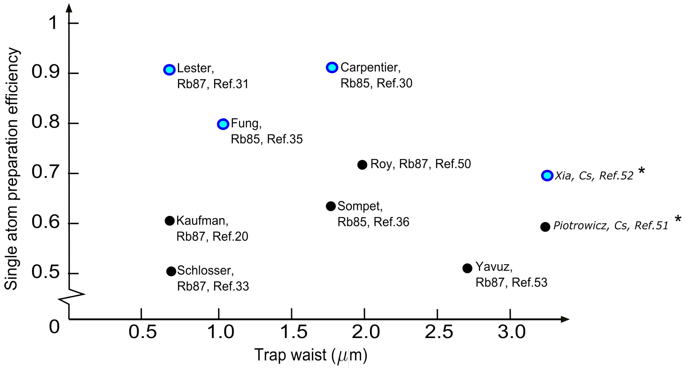
Figure 19 shows some examples of works that used light-assisted collisions as an approach to prepare a single atom [
20,
30,
31,
33,
35,
36,
50,
51,
52,
53]. Repulsive light-assisted collisions that favours the
loss channel generally results in higher preparation efficiency across different trap sizes and atomic species.
Figure 19.
Some examples of works with different atomic species using light-assisted collisions to prepare a single atom in a FORT with known trap waist. The single atom preparation efficiency is quoted as the single trap efficiency. Blue dots represent works that employs repulsive light-assisted collisions. Note: * The works using Cs are conducted in a blue-detuned FORT, so the individual trap size are not directly comparable to the other works that use red-detuned FORT.
Employing light-assisted collisions for the preparation of single atoms may be useful for future applications in quantum information processing with neutral atoms, where high filling efficiencies have to be achieved when loading atoms into multiple trap arrays with arbitary geometries, thus improving the scalability [
54]. The construction of hybrid quantum devices that interface microfabricated solid state structures and individual atoms in tight optical microtraps to attain better control in quantum metrology and sensing [
55,
56] may also implement these methods. With the high single atom prepartion efficiency in a microtrap, construction of a low entropy systems using a bottom up approach may be realized by combining efficient loading and ground state cooling of single neutral atom [
57,
58].


