Article

Mathematical Modeling of the Operation of an Expander-Generator Pressure Regulator in Non-Stationary Conditions of Small Gas Pressure Reduction Stations

by
Artem Evgenevich Belousov
* and
Egor Sergeevich Ovchinnikov
Department of Oil and Gas Transport and Storage, Saint Petersburg Mining University, 21st Line of Vasilievsky Island 2, 199106 Saint Petersburg, Russia
*
Author to whom correspondence should be addressed.
Mathematics 2022, 10(3), 393; https://doi.org/10.3390/math10030393
Submission received: 2 January 2022 / Revised: 22 January 2022 / Accepted: 26 January 2022 / Published: 27 January 2022
(This article belongs to the Special Issue Applied Mathematical Modelling and Dynamical Systems)

Abstract

:
Long-distance gas transfer requires high pressure, which has to be reduced before the gas is conveyed to the customers. This pressure reduction takes place at natural gas pressure reduction stations, where gas pressure is decreased by using gas flow energy for overcoming local resistance, represented by a throttling valve. This pressure energy can be reused, but it is difficult to implement it at small pressure reduction stations, as the values of unsteadiness significantly increase when the gas approaches consumers, whereas gas flow rate and pressure decrease. This work suggests replacing throttling valves at small pressure reduction stations for expander-generator units, based on volumetric expanders. Two implementations are proposed. A mathematical model of gas-dynamic processes, which take place in expander-generator units, was developed using math equations. With its help, a comparison was made of the stability of the operation of two possible control schemes in non-stationary conditions, and the feasibility of using an expander-generator regulator as a primary one for a small natural gas pressure reduction station was confirmed.

1. Introduction

Natural gas transportation and distribution networks are extensive; there are branched systems, with many natural gas pressure reduction stations (GPRSs), units for protection of gas pipelines from corrosion, and electrochemical protection (ECP) units. For example, the gas distribution network in Russia includes over 90,000 ECP units and over 300,000 GPRSs. Of these, only 4000 are large gas distribution stations; the rest are gas control units (GCUs) [1]. The main purpose of a GPRS is to lower the high pressure at which gas is transported over long distances [2] in order to compress gas and increase mass flow (up to 20 MPa) to a level required by consumers (mainly from 2 kPa to 0.6 MPa), and to maintain it at this level. The pressure is lowered gradually and sequentially as it approaches the end consumers, which makes it possible to reduce energy costs for transport. Thus, reduction is a standard operation in the transport and distribution of natural gas, which, at the moment, cannot be rejected. In this connection, the method of pressure reduction itself and the energy losses associated with it are of greatest interest.
The main reason for energy loss at GPRSs is the mechanism of reducing pressure by using gas flow energy for overcoming local resistance represented by the throttling valve of a pressure regulator (PR) [3]. The PR has some additional disadvantages, such as low accuracy and a need for reconfiguration when flow rate or gas pressure change before the PR, the inability to control it remotely, and the short service life of the sensitive element [4].
Research in the field of energy utilization has been conducted in the USA, Britain, Canada, Russia, and other countries since the 1930s. In Russia today, there are government programs which stimulate the development and introduction of energy-saving technologies [5,6].
It is obvious that using the flow of pressure energy to rotate an expander allows the energy to be utilized for various needs [7]. Such an approach was proposed by Millionshchikov as far back as 1947. Objectives and schemes of using expanders at GPRSs can be different: electrical generation, gas liquefaction [8], cogeneration [9,10,11,12], etc.
However, in most cases, the introduction of the most common turboexpanders in schemes of major GPRSs (for example, gas distribution plants) is justified in terms of economic and energy analysis [10,13,14]. The majority of existing turboexpanders have power within the range of 1 to 12 MW, and are exploited at stable high volume flow rates and pressure differentials [15].
Nowadays, expanders, with a capacity of under 50 kW, are the most appropriate devices being developed to supply energy to GPRSs. However, when the gas approaches consumers, gas flow rate and pressure decrease, and the unsteadiness of gas consumption increases. It leads to instability in the work of turbines, power surges in the electricity network of the expander-generator [16,17], as well as energy utilization inefficiency and a lack of economic feasibility of using an expander [18,19]. The above-mentioned factors affect most small GRPSs with flow rates under 500 m3/h and pressure differentials up to 6 atmospheres [20]. In such conditions, turboexpanders must work at high speed, which adds complexity to design, makes higher demands on the frequency of service, and, as a result, leads to economic inefficiency.
In addition, a significant decrease in the temperature of natural gas after its expansion in an expander should be taken into account. Burner gas heaters are traditionally used to restore its temperature [21], and various secondary energy resources, such as renewable [22,23,24] and low-potential energy sources [25,26,27,28], are widely considered promising.
The least studied is the issue of energy recovery in small reduction points, which have the worst conditions for the operation of energy recovery facilities. They are characterized by high unsteadiness of flow because of uneven gas extraction by consumers (hourly, daily, and seasonal), low flow rates and pressure drops, limited dimensions, and high distribution over the territory. Under such conditions, the use of known industrial plants is seriously limited by the requirements for stability and volumes of their supply, as well as economic aspects.
Despite the seeming unattractiveness of individual small GPRSs for energy utilization purposes, their total energy intensity is enormous. It can be effective to use expanders for the generation of electricity for the own needs of GPRSs and nearby ECP units to ensure their autonomy and the continuity of work of the gas supply system as a whole. This will reduce the consumption of energy from third-party sources (batteries, power lines), reduce the cost of connecting GPRSs and nearby ECPs to power lines, increase the efficiency of control and reduce human labor for manual control due to digitalization, and, in general, increase the efficiency and environmental friendliness of the natural gas transport and distribution system.
The power of energy-consuming devices of small GPRSs ranges from 0.5 to 1.0 kW. The largest amount of electricity is used for lighting during maintenance by personnel for several hours every 2–3 weeks [29]. The rest of the time, small GPRSs consume no more than 500 W. In the case of using telemechanics for an expander, an additional power of 15 W to 100 W is required.
The power consumed by cathodic protection stations depends on the length of the protected area, the resistivity of the ground, and other factors [30]. Today, the most common stations in gas distribution networks in Russia are ones with a capacity of 0.1–3 kW.
Considering all of the above, the solution to this problem can be to combine functions of a pressure regulator and a utilization unit in the form of an expander-generator based on a volumetric expander. In addition to the fact that today there are practically no reduction and utilization systems for small reduction points, the novelty of this solution lies, firstly, in the use of an expander directly as part of a pressure regulator, and not on a separate line of constant flow, which makes it possible to work with high non-stationarity, to increase the magnitude of the pressure drop effectively operated in the expander due to the absence of separate pressure regulators, and to significantly reduce the dimensions. Secondly, in the use of volumetric expanders, which make it possible to increase the reliability of the device due to its easy maintenance and the absence of the need for high-speed rotation at low flow rates and pressure drops [31,32,33].
This work suggests two options for using this reduction method, and the results of comparing their effectiveness and analyzing the possibility of using this method in general.

2. Materials and Methods

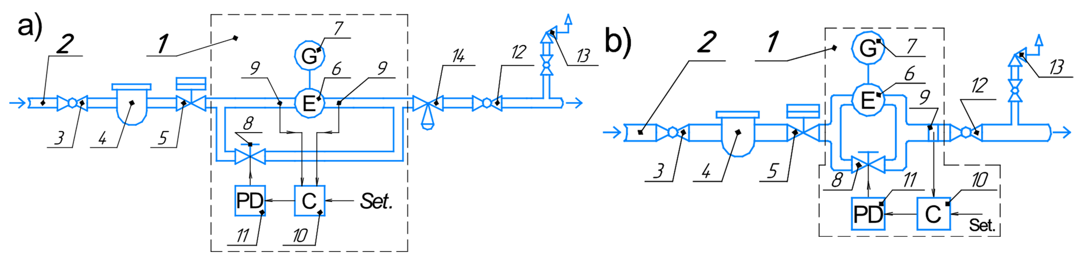
2.1. Functional Chart

There are various automatic control systems for expander-generator units (EGUs) [34,35], which are based on the principles of separation and switching of flows.
The frequently used scheme is the EGU connected in parallel with the GPRS reduction unit [36,37]. This scheme involves the use of an EGU under conditions of low unsteadiness of gas consumption by consumers, but it also includes all the disadvantages inherent in traditional pressure regulators.
Another scheme is the EGU sequentially connected with the traditional PR. This approach makes it possible to reduce the negative effect of the lowered temperature on the PR. However, there is no possibility of mechanical stabilization of the expander rotation speed in the event of significant unsteadiness of gas consumption by consumers [38].
The most attractive schemes are those that allow using the expander as a pressure regulator. The scheme presented in [25], in which the pressure is regulated at the outlet of the expander by changing the frequency of its rotation when adjusting the moment of resistance of the generator, allows abandoning the use of throttling valves. Unfortunately, the system is not described in detail, but based on similar systems and the need to maintain power quality [39], it can be assumed that its cost will be quite significant, especially for small reduction stations.
To use the expander-generator simultaneously as a utilization unit and a regulator, schemes of GPRS reduction lines, equipped with an expander-generator regulator (EGR), have been developed, which are also based on the principle of flow separation (Figure 1). However, the separation occurs immediately after the safety shut-off valve (SSV) 5 and before the safety relief valve (SRV) 13, which makes it possible to use the volumetric expander as the main gas pressure regulator. Therefore, the EGR is a part of the GPRS, and not an additional system located in parallel.
The proposed schemes use control systems with various stabilized characteristics:
(a)
stabilization of the pressure drop before and after the expander, which ensures the consistent speed of the expander rotor, but requires maintaining pressure at the outlet of the GPRS by an additional PR (RF patent No. 2620624, Figure 1a);
(b)
stabilization of the pressure at the outlet of the reduction station directly by the expander control system, without a separate stabilization loop for stabilizing the frequency of rotor rotation (RF patent No. 2662784, Figure 1b).
The most important parameters were chosen as target parameters during regulation. The rotational speed affects the quality of the generated electricity, and the outlet pressure affects the safety of operation of end-user equipment.
The devices mentioned above work as follows. After passing the SSV 5 on the reduction line 2, natural gas is divided into two flows, the proportions of which are determined by the rate of opening of the control valve 8. The control valve 8 is operated by the controller 10 via the performing device 11 depending on the discrepancy with the required value (setpoint):
(a)
of the pressure drop before and after the expander 6;
(b)
of the pressure at the outlet of the expander pressure regulator 1, determined by the sensors 9.
One flow enters the volumetric expander 6, where it expands and performs useful work, which is converted into mechanical, and then, with the help of an electric generator 7, electric energy. Another flow passes through the control valve 8, where it is throttled depending on the rate of valve opening. After that, the previously separated flows are combined into one, and:
(a)
they are sent to the PR 14, in which pressure is finally reduced to the required value;
(b)
they are sent to the consumer pipeline through the outlet shut-off valves 12.
The outlet pressure of the expander-generator 1 is defined by the volume of natural gas, which goes through the control valve 8 and the volumetric-type expander 6. As the rate of rotation of the expander depends on pressure drop, pressure maintenance in a consumer pipeline at a certain level and the consistency of pressure in a feed pipeline allow its stabilization. For that reason, option b is preferable.
In case the hydraulic stabilization system fails, regulation is possible by adjusting the gas supply through the expansion machine, by increasing or decreasing the rate of the rotor speed when changing the moment of the resistance generator, and by adjusting the take-off power [25,40].
Gas cooling due to expansion in the expander is not critical within the specified range of pressure and flow, so gas heating is not required [41].
A comparison of the effectiveness of the two proposed schemes is given below.

2.2. Expander Pressure Reduction Factors and Parameters

In one form or another, all pressure reduction stations consist of the same elements. This way, different external and internal factors have a similar influence. The factors considered when doing the work are given below.
The main factors of expander reduction:
  • gas parameters: z a v —average gas compressibility factor; R —individual gas constant; c p —specific heat capacity at constant pressure; ρ g —density; k —adiabatic exponent;
  • flow inputs: T 1 , p 1 —gas temperature and pressure; G r s —mass flow through the reduction station; K p n , K Q n —functions of gas pressure and flow seasonality;
  • parameters of pipes and fittings, including the control valve: f e , f s , f c , f c v —inner dimension area of the expander exhaust and starter passages, consumer pipeline, and control valve; λ —friction factor; ξ —local resistance coefficient; L c —consumer pipeline length;
  • environment parameter: T e n —environmental temperature;
  • expander physical and geometrical parameters: Ψ —number of working rotor blades; r 0 —expander rotor radius; φ 0 —injection zone end angle; ρ b —blade material density; σ —blade friction coefficient against the stator; j e q , j l , j e —the equivalent moment of inertia, load, and expander rotor inertia;
  • control system parameters: K i , K p —gain factors of integral and proportional terms; p 0 , ω 0 —required values of GPRS outlet pressure and rotor rate of rotation.
The main parameters of expander reduction are: p 2 , T 2 —GPRS outlet gas temperature and pressure; ω —expander rotor rate of rotation; N e —expander power; G e —mass flow through the expander.

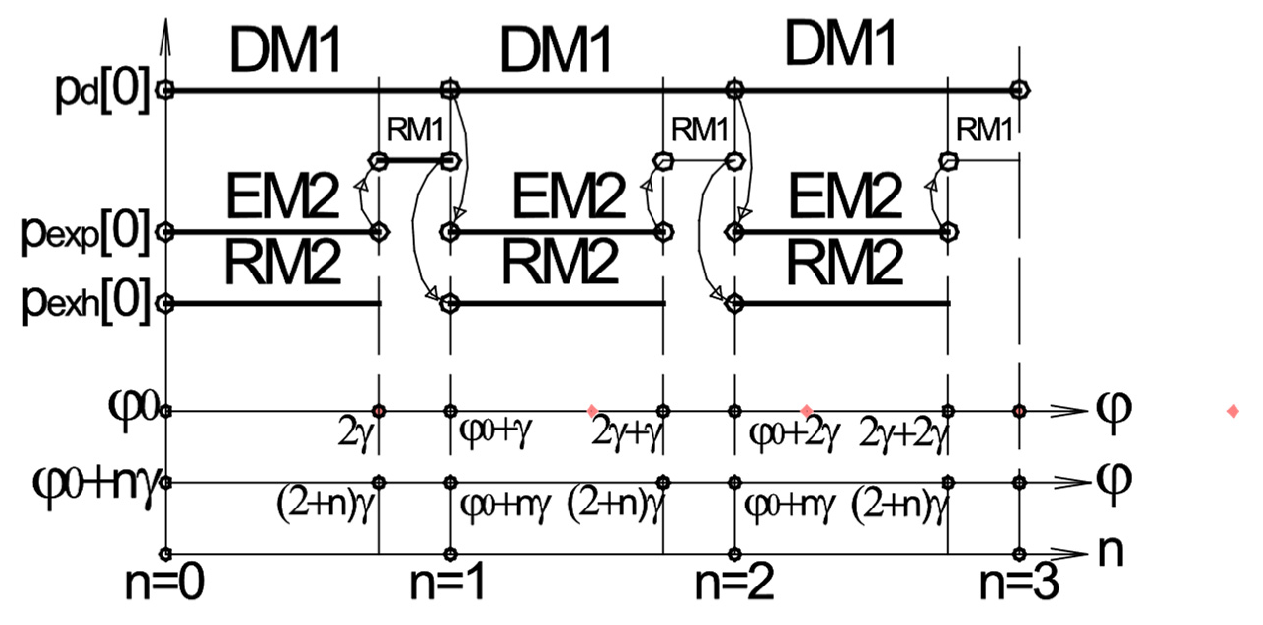
2.3. Logical Conditions

Screw expanders are most often considered in studies [32,42,43]; however, their capacities and power-to-weight ratios are better suited for larger consumers than those indicated above. Due to the similarity of the processes of volumetric expansion machines, the calculation was based on one of the most popular types of expanders, the vane expansion machine [44] (Figure 2).
The change in the working volume of the expander cavity depends on the height of the part of blade No. 1 protruding from the rotor (Figure 2a), which is calculated by the formula:
h 1 = e ( r 0 e + 1 ) 2 s i n 2 φ e · c o s φ r 0 ,
where r 0 —rotor radius; φ —rotor turning point; e —eccentricity.
For blade No. 2, following blade No. 1 (Figure 2a), this formula is transformed, considering the additional rotation by the angle γ between the blades:
h 2 = e ( r 0 e + 1 ) 2 s i n 2 ( φ + γ ) e · c o s ( φ + γ ) r 0 .
The elemental area of the volume of the working cavity is given by the formula of the sector area (Figure 2b):
d f e = ( r 0 + h 1 ) 2 d φ 2 r 0 2 d φ 2 = h 1 ( r 0 + h 1 2 ) d φ .
The increase in the volume of the chambers of discharge, expansion, and exhaust, respectively:
d V d = h 1 l ( r 0 + h 1 2 ) d φ ;
d V e x p = l ( h 2 ( r 0 + h 2 2 ) h 1 ( r 0 + h 1 2 ) ) d φ ;
d V e x h = h 2 l ( r 0 + h 2 2 ) d φ ,
where l —rotor (blade) axial length.
For one rotation of the rotor by an angle equal to the angle between two blades γ , a moment of the motion cycle is formed, which includes all three chambers and three blades, two of which, blades No. 1 and No. 2, are the most important (Figure 2a). Blade No. 1, by rotating, takes the place of blade No. 2, and then the same process repeats.
The process of rotor rotation is presented as consecutive cycle rotations of the rotor by an angle γ . The rotation is broken down into separate turns to record different equations of changing states of gas in the motion equation of the three chambers under consideration.
During the turn from blade No. 1 by an angle γ , the following moments will act (Figure 3):
  • from gas injection in the expander;
  • “part” of rotation resistance (RM1) at the end of the turn.
At the same time, the moments caused by blade No. 2 will act:
  • the moment from gas expansion in closed space between blades No. 1 and No. 2;
  • another “part” of rotation resistance (RM2).
At every turn by an angle γ , the effects of moments will repeat, as reflected in the counter of turns n. In subsequent rotations, the initial values of physical magnitudes will equal their final values at the previous rotation; these transitions are shown by arrows.
Due to limitations on the pressure in the discharge and exhaust chambers, the logical conditions equal:
n = n + 1 , a t φ = φ 0 + ( n + 1 ) γ n , i n o t h e r c a s e s p d = p 1 , i f   p d p 1 p d , i n o t h e r c a s e s p e x p = 0 , i f   ( n + 2 ) γ < φ < φ 0 + n γ p d , i f   φ = φ 0 + n γ p e x p , i n o t h e r c a s e s . p e x h = p e x p , i f   φ = ( n + 2 ) γ p c , i f   p e x h p c p e x h , i n o t h e r c a s e s
The exhaust process does not begin and end exactly at the beginning and end of the rotation by an angle γ (Figure 3). At the initial instant of time (n = 0), the exhaust zone is limited by blades No. 2 and No. 3, and at the end of the turn, by blades No. 1 and No. 2.
Due to the change of the blades which limit the exhaust chamber volume during the rotor rotation, control coefficients were added to the formula d V e x h , defined as:
{ K h 1 = { 0 , i f   ( n + 2 ) γ φ < φ 0 + n γ 1 , i n   o t h e r   c a s e s K h 2 = { 1 , i f   ( n + 2 ) γ φ < φ 0 + n γ 1 , i n   o t h e r   c a s e s K h 3 = { 0 , i f   φ 0 + n γ φ < ( n + 2 ) γ 1 , i n   o t h e r   c a s e s .
Given the control coefficients, the formula of the change in the exhaust cavity volume is calculated as:
d V e x h = ( K h 3 · h 3 ( r 0 + h 3 2 ) K h 2 · h 2 ( r 0 + h 2 2 ) K h 1 · h 1 ( r 0 + h 1 2 ) ) l · d φ ,
where h 3 —the height of the part of blade No. 3 protruding from the rotor.

2.4. Accounting of Gas Compressibility

The gas compressibility factor, taking into account intermolecular forces and molecular volumes, is used to account for the deviations in the behavior of real gas from that of the ideal gas. According to the standards [45], at a pressure of less than 15 MPa and a temperature range from 250 to 400 K, the compressibility factor is defined as:
z = 1 + A 1 p r e d + A 2 p r e d 2 ,
where:
A 1 = 0.39 + 2.03 T r e d 3.16 T r e d 2 + 1.09 T r e d 3 ;
A 2 = 0.0423 0.1812 T r e d + 0.2124 T r e d 2 ;
p r e d = p g p p c ,   T r e d = T g T p c ;
p p c = 0.1737 ( 26.831 ρ s t ) ,   T p c = 155.24 ( 0.564 + ρ s t ) ,
where p g , T g —pressure and temperature in the volume under consideration, respectively; p p c , p r e d ,—pseudo critical pressure and pressure reduced to pseudo critical conditions, respectively; T p c , T r e d —pseudo critical temperature and temperature reduced to pseudo critical conditions, respectively; ρ s t —gas density under standard conditions.

2.5. Differential Equation System

Most of the studies of expander gas expansion were carried out with the assumption that the mode of its operation is stationary, or by representing the unsteady mode as a set of stationary modes [5,46]. The presented models for unsteady modes most often have a limited number of differential equations, the use of which is replaced by assumptions [47].
The gas entering the discharge chamber expands and does work. Therefore, the internal energy of the gas is calculated according to the formula:
d U d = d W d d A d ,
where W d —the amount of heat which is supplied to gas in the discharge chamber; d A d —the elementary work of gas in the discharge chamber.
After transformations, the equation of pressure change in the discharge chamber has the form:
d p d d t = k R T d z d V d G d p d ( R z d + c v ) V d c v d V d d t + p d z d d z d d t .
The equation of the temperature change in the discharge chamber is expressed similarly, as follows:
d T d d t = ( k T 1 T d ) z d R T d p d V d G d z d R T d c v V d d V d d t .
Experimental data demonstrate the closeness of the gas flow processes in industrial systems to isothermic ones [48]. In that case, gas mass flow from the pipeline in the expander discharge chamber is found from the equation system:
G d = f d p 1 R T 1 1 p d p 1 2 ξ d 2 l n p d p 1 , i f   p d r e d p 1 < p d p 1 1 f d p d r e d R T 1 , i f   p d r e d p 1 p d p 1 , 2 l n p d r e d p 1 + p 1 p d r e d 2 = 1 + ξ d
where p d r e d —gas limit pressure in the discharge chamber at which the maximum mass flow is achieved.
The isolated volume of gas, moving into the next chamber, expands, doing work and losing internal energy:
d U e x p = d A e x p .
Likewise, the equation of the pressure change in the expansion chamber is derived:
d p e x p d t = p e x p z e x p d z e x p d t p e x p ( R z e x p + c v ) V e x p c v · d V e x p d t .
The equation of the temperature change in the expansion chamber has the form:
d T e x p d t = z e x p R T e x p c v V e x p d V e x p d t .
Then, the gas flows out of the exhaust chamber, doing work, which interferes with the expander rotor rotation.
The equation of the internal energy change:
d U e x h = w e x h d m e x h d A e x h ,
where w e x h —the specific quantity of heat which the gas gives off in the exhaust chamber; m e x h —the mass of gas in the exhaust chamber.
As a result of the transformation, the equation of the pressure change in the exhaust chamber takes the form:
d p e x h d t = p e x h z e x h d z e x h d t k R T e x h z e x h V e x h G e x h p e x h ( R z e x h + c v ) V e x h c v d V e x h d t ,
where z e x h —the gas compressibility factor in the exhaust chamber; G e x h —gas mass flow in the exhaust chamber.
The temperature change in the exhaust chamber is calculated as:
d T e x h d t = ( k + 1 ) z e x h R T e x h 2 p e x h V e x h G e x h z e x h R T e x h c v V e x h d V e x h d t .
From the exhaust chamber, the gas flows into the pipeline with high resistance. From the expander, the gas goes into the branch pipe, expanding and cooling. Due to friction on pipeline walls and internal resistance, the gas is heated. As such, the gas outflow process can be considered as isothermic; then, the mass flow from the expander is defined by a similar formula for gas injection.
The Euler–Lagrange equation is used to derive the rotor rotation equation:
j e q d 2 φ d t 2 = M e M f r M g ,
where M e —the algebraic sum of moments in the discharge, expansion, and exhaust chambers; M f r = Ψ · σ m b r c g · ω 2 ( r 0 + h a v ) —the moment of friction of the blades against the stator, where m b , r c g , h a v —the mass, the radius of the center of gravity, and the average height of the protruding part of the blade, respectively; σ —the coefficient of friction of the blades against the stator; M g —the generator moment of resistance.
During the creation of the stabilization system model, the proportional-integral (PI) law of regulation was used, owing to its frequent use for valve control. With the stabilization of the rotation speed of the expander rotor, the general view of the PI-regulator output signal has the form:
Y ( t ) = K p [ ω ( t ) ω 0 ] + K i 0 t [ ω ( t ) ω 0 ] d t ,
with output pressure stabilization:
Y ( t ) = K p [ p c ( t ) p 0 ] + K i 0 t [ p c ( t ) p 0 ] d t ,
where P ( t ) and I ( t ) —proportional and integral links of the regulation law; ω 0 and ω ( t ) —the required frequency and instantaneous frequency of the expander rotation; p 0 and p c ( t ) —the required output pressure and instantaneous output pressure at the GPRS.
The integral term of the mathematical model is replaced with an additional differential equation, the derivative d I d t , which is equal to the integral:
d I d t = K i [ ω ( t ) ω 0 ] ,
or
d I d t = K i [ p c ( t ) p 0 ] .
The integration time for the integral component of the control law equals the calculated time step for solving the system of Equation (25).
The gas flow through the control valve 8 at subcritical and critical flows can be calculated by the Saint-Venant − Wantzel formula:
G c v = μ c v π d s h s p ϵ ( t ) p 1 2 R T 1 · k k 1 p c p 1 2 k p c p 1 k + 1 k , i f p 1 p c < k + 1 2 k k 1 , μ c v π d s h s p ϵ ( t ) p 1 k R T 1 2 k + 1 k + 1 2 ( k 1 ) , i f p 1 p c k + 1 2 k k 1
where μ c v —the coefficient of gas flow through the valve; d s —valve seat diameter; h s p —full valve spindle travel; ϵ ( t ) —the rate of valve orifice opening, which in the range from 0 to 1, is described by the following equation:
ϵ ( t ) = { v e l ,   i f   ϵ ( t ) < Y ( t ) v e l ,   i f   ϵ ( t ) Y ( t ) ,
where v e l —constant speed of opening or closing of the control valve by an electric actuator with a positioner. Other logic conditions must be applied when using other drives.
Similarly, the equation of the change in the gas state taking place when previously divided gas flows mix in the cavity [49] after the expander is defined as:
d p c d t = p c z c d z c d t + z c R k V c ( T e x h G e x h + T c v G c v T c G c ) ,
where z c —the gas-compressibility factor in the cavity; V c —cavity volume.
The mass flow of gas, taken by consumers after the EGR, equals [50]:
G c = ( p 2 p e q n o m ) ( 100 d c ) 5 626.1 λ L c ρ s t 3600 ,
where p e q n o m —the nominal pressure of the gas-using equipment.
In the process of gas expansion in the cavity after the expander, the temperature changes according to:
d T c d t = z c R T c p c V c ( ( k T e x h T c ) G e x h + ( k T c v T c ) G c v ( k 1 ) T c 2 G c ) .
The received mathematical model is the combination of constants and inputs, auxiliary equations, differential equations and their inputs, and logical conditions. Also, logical conditions, modelling the expander rotor rotation and preserving the changing parameters in the preset range, are used. Different kinds of d I d t are used in options of the stabilization system a and b.
In that way, the system of basic differential equations has the form:
j e q d ω d t = p d l h 1 r 0 + h 1 2 + p e x p l h 2 h 1 r 0 + h 1 + h 2 h 1 2 p e x h l h 2 r 0 + h 2 2 M f r M g ; d p d d t = k V d R T 1 G d p d · d V d d t ; d p e x p d t = p e x p z e x p d z e x p d t p e x p R z e x p + c v V e x p c v · d V e x p d t ; d p e x h d t = p e x h z e x h d z e x h d t k R T e x h z e x h V e x h G e x h p e x h R z e x h + c v V e x h c v d V e x h d t ; d p c d t = p c z c d z c d t + z c R k V c T e x h G e x h + T c v G c v T c G c ; ( a ) d I d t = K i ω ( t ) ω 0 ; ( b ) d I d t = K i p c ( t ) p 0 ; ϵ ( t ) = v e l , i f ϵ ( t ) < Y ( t ) v e l , i f ( t ) Y ( t ) d T d d t = k T 1 T d z d R T d p d V d G d z d R T d c v V d d V d d t ; d T e x p d t = z e x p R T e x p c v V e x p d V e x p d t ; d T e x h d t = ( k + 1 ) z e x h R T e x h 2 p e x h V e x h G e x h z e x h R T e x h c v V e x h d V e x h d t ; d T c d t = z c R T c p c V c k T e x h T c G e x h + k T c v T c G c v ( k 1 ) T c 2 G c .
As the nonlinearity of the system (25) is high, and cyclical operation of some logical conditions describing the rotor rotation is required, the explicit four-stage Runge–Kutta method is used.

3. Results and Discussion

The characteristics of the working serial equipment (Appendix A), which was used in creating the prototype (Figure 4), were taken as the inputs. The adequacy of the model was confirmed by comparing the results of the expander acceleration simulation (Figure 5b) with experimental data (Appendix B).
The final charts (Figure 5a) for every chamber are periodic curves, and the processes are quasi-stationary, as the general process of change in the state of gas occurs in the separate zones of injection, expansion, and exhaust. The graph shows the complete change in gas pressure in every expander chamber taking place when gas passes through each of them. Transition to the next zone along the rotation is marked by a jump on the graph.
From the graph (Figure 5b), it follows that the vane expander has an aperiodic transition process without transient overshoot, which is desirable when acting as a generator drive.
In order to test the sustainability of the EGR system under conditions of unsteadiness, some step disturbances were set:
  • reduction of mass gas consumption by consumers by 30%;
  • increase in mass gas consumption by consumers by 30%;
  • decrease in upstream pressure at the GPRS by 5%;
  • increase in upstream pressure at the GPRS by 5%.
The two control schemes were compared under the same conditions and assumptions.
The results are reflected in graphs in a dimensionless form, so the steady-state value of pressure after the EGR, and the frequency of the expander rotor rotation before disturbance with the control valve open by ε = 50 % , were used as unit segments. The gain factors of the law of control are presented in Table 1.
Both with a decrease and increase in gas offtake, EGRs in the two embodiments (Figure 1) properly stabilize disturbances, and the stabilized parameters remain within the specified limits (Figure 6 and Figure 7). Straight horizontal parts of pressure change after the expander are due to the linear movement of the control valve spindle. Pressure stabilization takes less time than frequency stabilization, but only slightly (Table 2).
Figure 6 and Figure 7 show such a clear point of reaching the required pressure value for case (b), due to the fact that the control valve maintains pressure directly, whereas for case (a), indirectly. In addition, an electric valve actuator with a positioner is used, which in practice in this operation scheme has shown resistance to unwanted transition through the target position values. In this regard, no additional delays were introduced into the equations during the simulation. In addition to this, the integral part of the control law was calculated from a small step time, which is unattainable in practice, and increases the stabilization accuracy. Therefore, an idealized comparison of the two control schemes was made.
A more significant impact on the reduction and the utilization parameters is provided by a pressure change in the discharge line (Figure 8 and Figure 9). While stabilizing, despite the fact that during the transition process, the frequency of the rotor rotation is never out of allowable range 2 Δ = 10 % , the original value cannot be achieved.
With the stabilization of the EGR outlet pressure, the frequency of rotor rotation changes more than with an increase or decrease in gas consumption by consumers. However, the EGR outlet pressure in this case reaches its original value.
It can be seen from Table 2 that the average transition process time in the option of EGR outlet pressure stabilization is lower. This can be explained by the control valve 8, which directly affects the controlled parameter. If the rotor rotation frequency is stabilized, then the control valve indirectly affects the controlled parameter, thereby increasing the system inertia.
Also, Table 1 shows that different ways of frequency stabilization require different gain factors of the law of control, which is ensured by a controller with self-tuning.
With both methods of stabilization, the pressure fluctuations before the PR do not go beyond the permissible ±25%, and the GPRS outlet pressure fluctuations do not go beyond ±10%. Thus, the possibility of using any of the two stabilization systems has been confirmed. In general, the method of pressure stabilization at the outlet of the reduction point is more preferable, since, in addition to a shorter stabilization time, it has a lower cost of equipment, and has a higher energy recovery efficiency due to a more complete response of the pressure drop in the expander, rather than in an additional pressure regulator at the output, which is not required in this case. At the same time, due to the absence of frequency stabilization, an enhanced set of elements of the system for maintaining the quality of generated electricity is needed. However, these items are cheaper than an additional pressure regulator. All this gives a greater economic potential for the reduction method, where the expander-generator unit is both a utilization plant and the only pressure regulator.
It must be recalled that in reality, the duration and quality of the transition processes can differ significantly from the modelled ones due to the strong influence of the technical characteristics of the applied equipment on transition processes.
In the process of expander expansion, natural gas is cooled, and the degree of its cooling is higher than during throttling due to the additional technical work performed by the gas. In addition, the systems of small GPRSs do not provide for the installation of gas flow heaters to compensate for the expander cooling. Only in the coldest northern regions, to prevent equipment freezing due to weather conditions, the GPRS unit is heated, but not the gas flow. Based on this, it is necessary to consider the possibility of cooling the gas at the outlet of the expander to temperatures below the dew point, as well as the precipitation of gas hydrates.
Besides various additional systems for recovering the gas temperature at the outlet of the GPRS, in the case of low power of expander generators, low flow rates, and pressure drops, partial temperature recovery is possible due to released heat caused by friction [4].
In accordance with the scheme shown in Figure 1b, the natural gas stream is divided into two: one passes through the expander, and the other is throttled through the control valve, and then these streams of different temperatures are again mixed into one, with an average temperature. Thus, the temperature at the outlet of the EGR depends on the degree of opening the control valve.
Using the developed model, the value of the temperature drop at the outlet from the EGR was calculated depending on the degree of opening the applied control valve (Figure 10). The inlet temperature was taken to be 293 K, and the absolute pressure was 300 kPa (outlet pressure—100 kPa).
In operating modes, the temperature drop is from 10 °C to 50 °C, which indicates the risk of hydrate formation. However, the following factors will minimize the negative consequences:
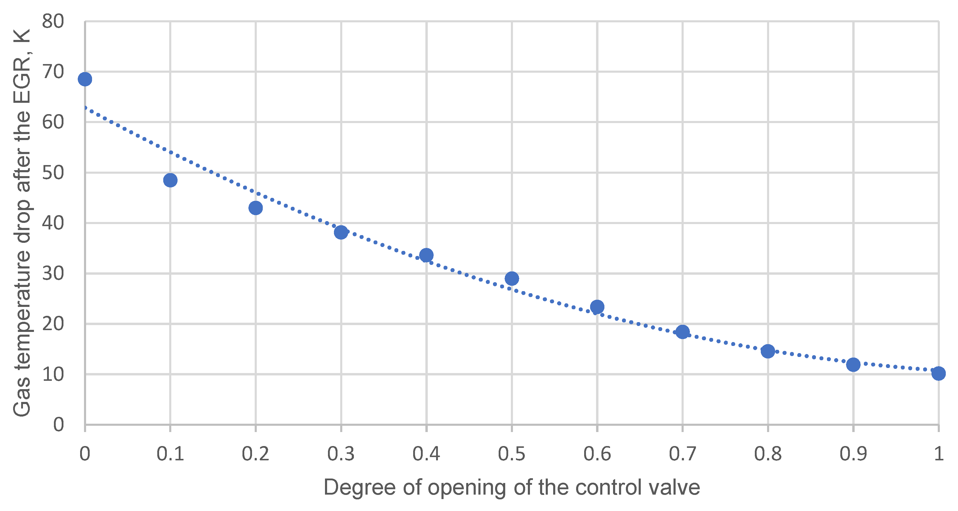
  • natural gas in the gas distribution system is the driest in the entire gas supply system, since it is the closest to the consumer and has been dehydrated many times on its way;
  • gas leaves the EGR under a low overpressure of about 0.05 kPa, which prevents hydrate formation;
  • volumetric expanders are low-maintenance and can deal reasonably well with gas flow irregularities;
  • the mass flow rate of gas through small GPRSs (GCUs) is quite low, and therefore does not have a high refrigeration content; therefore, due to heat exchange, it rather quickly heats up from the environment.
Thus, the risk of hydrate formation exists only during the operation of an unheated GPRS casing in the northern regions.
For comparison, during experiments with an EGR with a fully closed control valve, at a maximum flow rate ( 60   nm 3 / h ) and at a pressure drop (285 kPa), the drop in air temperature during its expander expansion was 8 °C.

4. Conclusions

An expander-generator pressure regulator is proposed, which simultaneously performs the functions of a pressure regulator with remote control and a unit for generating electricity for the needs of small reduction stations (telemetry, telemechanics, lighting) and nearby ECP units, due to the utilization of pressure energy.
A mathematical model of the expander reduction process has been developed, which allows calculating the gas-dynamic parameters of gas and the mechanical parameters of the expander, working under transient conditions. It can be used as a part of the methodology for selecting the parameters of volumetric expanders intended for operation at small reduction stations.
The ability of EGR expansion and the proposed stabilization systems to work steadily under conditions of unsteady gas consumption by consumers and changes in the GPRS upstream pressure, is confirmed by mathematical simulation. At the same time, the scheme using an expander-generator regulator as a primary one showed greater efficiency.
Despite the fact that the priority goal of pressure reduction stations is to maintain the outlet pressure in a certain range, the quality of the generated electricity at an unstable rotation frequency of the EGR rotor must also be ensured at a certain level. This issue was not discussed in this work.

Author Contributions

Conceptualization, methodology, resources, software, validation, writing—original draft preparation A.E.B. Software, visualization, writing—review and editing E.S.O. All authors have read and agreed to the published version of the manuscript.

Funding

This research received no external funding.

Institutional Review Board Statement

Not applicable.

Informed Consent Statement

Not applicable.

Conflicts of Interest

The authors declare no conflict of interest.

Abbreviations

GPRa gas pressure reduction station
ECPan electrochemical protection
GCUa gas control unit
PRa pressure regulator
EGUan expander-generator unit
EGRan expander-generator regulator
SSVa safety shut-off valve
SRVa safety relief valve
PIa proportional-integral
PIDa proportional-integral-derivative

Nomenclature

A 1 , A 2 compressibility factor coefficients
A d elementary work of gas in the discharge chamber
A e x p work performed by gas during expansion
b b blade thickness
c p specific heat capacity at constant pressure
DMdischarge moment
d s valve seat diameter
d c inner diameter of consumer pipeline
d f e elemental area of the volume of the working cavity
e eccentricity of the rotor relative to the stator
ϵ ( t ) the rate of valve orifice opening
EMexpansion moment
ξ local resistance coefficient
ξ i local resistance coefficient of the inlet passage
ξ e local resistance coefficient of the exhaust passage
f e , f s , f c , f c v inner dimension area of the expander exhaust and starter passages, consumer pipeline, and control valve
Ψ number of working rotor blades
φ rotor turning point
φ 0 injection zone end angle
f d area of the internal section of the launch channel of the expander
f i inlet passage cross-sectional area
f c v full flow area of the control valve
G r s mass flow through the reduction station
G e mass flow through the expander
G d gas mass flow from the pipeline in the expander discharge chamber
G e x h gas mass flow through the exhaust chamber
G c v gas flow through the control valve
G c gas flow through the pressure reduction station
h 1 height of the part of blade No. 1 protruding from the rotor
h 2 height of the part of blade No. 2 protruding from the rotor
h 3 height of the part of blade No. 3 protruding from the rotor
h b blade height
h s p full valve spindle travel
h a v average height of the protruding part of the blade
I ( t ) integral link of the regulation law
j e q , j l , j e the equivalent moment of inertia, load, and expander rotor inertia
k adiabatic exponent
K p n , K Q n functions of gas pressure and flow seasonality
K i , K p gain factors of integral and proportional terms
K h 1 , K h 2 , K h 3 control coefficients
K l expander coefficient of leaking
L c consumer pipeline length
l rotor (blade) axial length
m e x h mass of gas in the exhaust chamber
m b the mass of the protruding part of the blade
M e the algebraic sum of moments in the discharge, expansion, and exhaust chambers
M f r the moment of friction of the blades against the stator
M g the generator moment of resistance
μ c v the coefficient of gas flow through the valve
N e expander power
η e expander efficiency factor
p d pressure in the discharge chamber
p e x p pressure in the expansion chamber
p e x h pressure in the exhaust chamber
p p c , p r e d ,pseudo-critical pressure and pressure reduced to pseudo-critical conditions
ρ s t gas density under standard conditions
ρ b blade material density
p d r e d gas limit pressure in the discharge chamber
p 0 , p c ( t ) the required output pressure and instantaneous output pressure at the GPRS
p e q n o m nominal pressure of the gas-using equipment
p n . c . atmosphere pressure
P ( t ) proportional link of the regulation law
p 1 GPRS inlet gas pressure
p 0 required value of GPRS outlet pressure
p 2 GPRS outlet gas pressure
p g pressure in the volume under consideration
r 0 expander rotor radius
r c g radius of the center of gravity of the protruding part of the blade
RMrotation resistance moment
r 1 stator inner radius
R individual gas constant
T e n environmental temperature
T p c , T r e d pseudo-critical temperature and temperature reduced to pseudo-critical conditions
T d temperature in the discharge chamber
T e x p temperature in the expansion chamber
T e x h temperature in the exhaust chamber
T c v gas temperature in the control valve
T c temperature in the cavity of the flow connection behind the expander regulator
T 1 GPRS inlet gas temperature
T 2 GPRS outlet gas temperature
T g temperature in the volume under consideration
U d internal energy of the gas in the discharge chamber
U e x p gas internal energy in the expansion chamber
U e x h gas internal energy in the exhaust chamber
ν s t gas kinematic viscosity at standard conditions
v e l constant speed of opening or closing of the control valve by an electric actuator with a positioner
V c cavity volume
ω expander rotor rate of rotation
W d amount of heat which is supplied to gas in the discharge chamber
w e x h specific quantity of heat which the gas gives off in the exhaust chamber
ω 0 , ω ( t ) the required frequency and instantaneous frequency of the expander rotation
γ angle between adjacent blades
Y ( t ) output signal
z compressibility factor
z d compressibility factor of gas in the discharge chamber
z e x p compressibility factor of gas in the expansion chamber
z e x h compressibility factor of gas in the exhaust chamber
z c the gas-compressibility factor in the cavity
σ the coefficient of friction of the blades against the stator
λ friction factor

Appendix A

Table A1. Input data.
ParameterSymbolsValueDimension
Stator inner radius r 1 0.0233m
Expander rotor radius r 0 0.02m
Eccentricity of the rotor relative to the stator e 0.00328m
Number of blades in the expanderFor modeling Ψ 6pieces
For checking the adequacy of the model5
Blade length l 0.05m
Blade thickness b b 0.005m
Blade height h b 0.0131m
Injection zone end angleFor modelling φ 0 1.25664rad
For checking the adequacy of the model1.0472
Angle between adjacent bladesFor modelling γ 1.25664rad
for checking the adequacy of the model1.0472
Blade material density ρ b 1300kg/m3
Coefficient of correction of sliding friction force according to the results of the experiment-0.575dim
Coefficient of friction of the blades against the stator σ 0.2dim
Adiabatic exponentNatural gas k 1.3dim
Air1.4
Gas density at standard conditionsNatural gas ρ s t 0.73kg/m3
Air1.2
Heat capacity at constant pressureNatural gas c p 3200J/kg·K
Air1005
Individual gas constantNatural gas R 520J/kg·K
Air287
Gas kinematic viscosity at standard conditionsNatural gas ν s t 15.06·10−6Pa·s
Air14.3·10−6
Gas temperature at the inlet to the GPRS T 1 293K
Expander coefficient of leaking K l 0.65dim
Expander efficiency factor η e 0.85%
Exhaust passage cross-sectional area f e 0.00008m2
Inlet passage cross-sectional area f i 0.00008m2
Atmosphere pressure p n . c . 100,000Pa
Local resistance coefficient of the inlet passage ξ i 20dim
Local resistance coefficient of the exhaust passage ξ e 20dim
Gas flow through valve coefficient μ c v 0.8dim
Inner diameter of consumers pipeline d c 0.05m
Time of complete valve reset-17s
Consumer pipeline length L c 50m
Full flow area of the control valve f c v 0.000176m2

Appendix B

Figure A1. Rotation frequency of the expander rotor according to experimental data.
Mathematics 10 00393 g0a1

References

  1. AO “Gazprom Gazoraspredelenie”. Available online: http://gazoraspredelenie.gazprom.ru (accessed on 1 November 2020).
  2. Kostowski, W.J.; Usón, S. Comparative evaluation of a natural gas expansion plant integrated with an IC engine and an organic Rankine cycle. Energy Conv. Manag. 2013, 75, 509–516. [Google Scholar] [CrossRef]
  3. Kargaran, M.; Arabkoohsar, A.; Hagighat-Hosini, S.J.; Farzaneh-Kord, V. The second law analysis of natural gas behavior within a vortex tube. Therm. Sci. 2013, 17, 1079–1092. [Google Scholar] [CrossRef]
  4. Sheikhnejad, Y.; Simões, J.; Martins, N. Energy harvesting by a novel substitution for expansion valves: Special focus on city gate stations of high-pressure natural gas pipelines. Energies 2020, 13, 956. [Google Scholar] [CrossRef] [Green Version]
  5. Kashtanova, I.I. The economic mechanism for the implementation of energy conservation policies. Notes Min. Inst. 2009, 184, 218–224. [Google Scholar]
  6. Voronina, Y.V.; Iseeva, L.I. Analysis of the effectiveness of state regulation in the fuel and energy complex of Russia. Notes Min. Inst. 2009, 182, 177–180. [Google Scholar]
  7. Kostowski, W. The possibility of energy generation within the conventional natural gas transport system. Stroj. J. Theory Appl. Mech. Eng. 2010, 52, 429–440. [Google Scholar]
  8. He, T.B.; Ju, Y.L. Design and optimization of natural gas liquefaction process by utilizing gas pipeline pressure energy. Appl. Therm. Eng. 2013, 57, 1–6. [Google Scholar] [CrossRef]
  9. Gord, M.F.; Hashemi, S.; Sad, M. Energy destruction in Iran’s natural gas pipe line network. Energy Explor. Exploit. 2007, 25, 393–406. [Google Scholar] [CrossRef]
  10. Badami, M.; Modica, S.; Portoraro, A. A biofuel-based cogeneration plant in a natural gas expansion system: An energetic and economic assessment. Appl. Therm. Eng. 2017, 118, 52–61. [Google Scholar] [CrossRef]
  11. Farzaneh-Gord, M.; Sadi, M. Enhancing energy output in Iran’s natural gas pressure drop stations by cogeneration. J. Energy Inst. 2008, 81, 191–196. [Google Scholar] [CrossRef]
  12. Leusheva, E.L.; Morenov, V.A. Development of combined heat and power system with binary cycle for oil and gas enterprises power supply. Neftyanoe Khozyaystvo-Oil Ind. 2017, 7, 104–106. [Google Scholar] [CrossRef]
  13. Rahman, M.M. Power generation from pressure reduction in the natural gas supply chain in Bangladesh. J. Mech. Eng. 2010, 41, 89–95. [Google Scholar] [CrossRef] [Green Version]
  14. Danieli, P.; Carraro, G.; Lazzaretto, A. Thermodynamic and economic feasibility of energy recovery from pressure reduction stations in natural gas distribution networks. Energies 2020, 13, 4453. [Google Scholar] [CrossRef]
  15. Fokin, G.A. Development and creation of autonomous power plants of low power with an expansion turbine. Gas Turbine Technol. 2010, 1, 10. [Google Scholar]
  16. Mohod, S.W.; Aware, M.V. A STATCOM-control scheme for grid connected wind energy system for power quality improvement. IEEE Syst. J. 2010, 4, 346–352. [Google Scholar] [CrossRef]
  17. Hossain, M.J.; Pota, H.R.; Ramos, R.A. Robust STATCOM control for the stabilisation of fixed-speed wind turbines during low voltages. Renew. Energy 2011, 36, 2897–2905. [Google Scholar] [CrossRef] [Green Version]
  18. Repin, L.A. Possibilities of using natural gas pressure energy at small gas distribution stations. Energosberezhenie 2004, 3, 34–39. [Google Scholar]
  19. Seresht, R.T.; Jalalabadi, H.K.; Rashidian, B. Retrofit of Tehran City Gate Station (C.G. S.No.2) by Using Turboexpander. In Proceedings of the ASME 2010 Power Conference, Chicago, IL, USA, 13–15 July 2010. [Google Scholar] [CrossRef]
  20. Taleshian, M.; Rastegar, H.; Askarian, H. Modeling and power quality improvement of grid connected induction generators driven by turbo-expanders. Int. J. Energy Eng. 2012, 2, 131–137. [Google Scholar] [CrossRef]
  21. Rastegar, S.; Kargarsharifabad, H.; Shafii, M.B.; Rahbar, N. Experimental investigation of the increasing thermal efficiency of an indirect water bath heater by use of thermosyphon heat pipe. Therm. Sci. 2020, 24, 4277–4287. [Google Scholar] [CrossRef]
  22. Arabkoohsar, A.; Machado, L.; Koury, R.N.N. Operation analysis of a photovoltaic plant integrated with a compressed air energy storage system and a city gate station. Energy 2016, 98, 78–91. [Google Scholar] [CrossRef]
  23. Arabkoohsar, A.; Farzaneh-Gord, M.; Deymi-Dashtebayaz, M.; Machado, L.; Koury, R.N.N. A new design for natural gas pressure reduction points by employing a turbo expander and a solar heating set. Renew. Energy 2015, 81, 239–250. [Google Scholar] [CrossRef]
  24. Schipachev, A.M.; Dmitrieva, A.S. Application of the resonant energy separation effect at natural gas reduction points in order to improve the energy efficiency of the gas distribution system. J. Min. Inst. 2021, 248, 253–259. [Google Scholar] [CrossRef]
  25. Xiong, Y.; An, S.; Xu, P.; Ding, Y.; Li, C.; Zhang, Q.; Chen, H. A novel expander-depending natural gas pressure regulation configuration: Performance analysis. Appl. Energy 2018, 220, 21–35. [Google Scholar] [CrossRef]
  26. Farzaneh-Gord, M.; Ghezelbash, R.; Sadi, M.; Moghadam, A.J. Integration of vertical groundcoupled heat pump into a conventional natural gas pressure drop station: Energy, economic and CO2 emission assessment. Energy 2016, 112, 998–1014. [Google Scholar] [CrossRef]
  27. Borelli, D.; Devia, F.; Lo Cascio, E.; Schenone, C. Energy recovery from natural gas pressure reduction stations: Integration with low temperature heat sources. Energy Convers. Manag. 2018, 159, 274–283. [Google Scholar] [CrossRef] [Green Version]
  28. Barbarelli, S.; Florio, G.; Scornaienchi, N.M. Developing of a small power turbine recovering energy from low enthalpy steams or waste gases: Design, building and experimental measurements. Therm. Sci. Eng. Prog. 2018, 6, 346–354. [Google Scholar] [CrossRef]
  29. Fokin, G.A. Methodology for the Creation of Autonomous Turbine Sources of Electrical Energy Using the Energy of Compressed Natural Gas for the Own Needs of the Gas Transmission System of Russia. Ph.D. Thesis, Peter the Great St. Petersburg Polytechnic University, St. Petersburg, Russia, 2015. [Google Scholar]
  30. Krizsky, V.; Aleksandrov, P.; Kovalskii, A.; Viktorov, S. Mathematical modelling of Electric and Magnetic Fields of main pipelines cathodic protection in electrically anisotropic media. E3S Web Conf. 2021, 225, 1–4. [Google Scholar] [CrossRef]
  31. Karasevich, V.A.; Chernykh, A.S.; Yakovlev, A.A. Prospects for the use of autonomous energy sources in the transportation and distribution of gas. Sci. J. Russ. Gas Soc. 2016, 1, 59–61. [Google Scholar]
  32. Diao, A.; Wang, Y.; Guo, Y.; Feng, M. Development and application of screw expander in natural gas pressure energy recovery at city gas station. Appl. Therm. Eng. 2018, 142, 665–673. [Google Scholar] [CrossRef]
  33. Cipollone, R.; Contaldi, G.; Sciarretta, A.; Tufano, R.; Villante, C. A theoretical model and experimental validation of a sliding vane rotary compressor. In Proceedings of the International Compressor Engineering Conference at Purdue University, West Lafayette, IN, USA, 17–20 July 2006; 2006. [Google Scholar]
  34. Panarin, M.V.; Pakhomov, S.N.; Vorobiev, N.Y.; Tsarkov, G.Y. Turbine Expander Control Device. Patent RF 2579301, 10 April 2016. [Google Scholar]
  35. Aksenov, D.T.; Aksenova, G.P. A Method for Sustainable Gas Supply by a Gas Distribution Station with an Energy Refrigeration Complex Using Overpressure Energy of Natural Gas to Generate Electricity and Cold, and a System for Implementing the Method. Patent RF 2346205, 10 February 2009. [Google Scholar]
  36. Pozivil, J. Use of expansion turbines in natural gas pressure reduction stations. Acta Montan. Slovaca 2004, 9, 258–260. [Google Scholar]
  37. Neseli, M.A.; Ozgener, O.; Ozgener, L. Energy and exergy analysis of electricity generation from natural gas pressure reducing stations. Energy Convers. Manag. 2015, 93, 109–120. [Google Scholar] [CrossRef]
  38. Turboexpanders. 2020. Available online: http://detander.com/turbodet/ (accessed on 1 November 2020).
  39. Zamyatin, E.; Voytyuk, I.; Zamyatina, E. Increasing the energy efficiency of an enterprise by point compensating of power quality distortions. E3S Web Conf. 2019, 140, 04010. [Google Scholar] [CrossRef] [Green Version]
  40. Zhemchugov, G.A.; Plekhanov, S.N. Regulation of turboexpander sources of electrical energy based on closed gas turbine circuits. Questions of Electromechanics. VNIIEM Proc. 2001, 100, 125–146. [Google Scholar]
  41. Chelaznov, A.A. State and prospects for the use of autonomous sources at the enterprises of OAO Gazprom. In Proceedings of the Meeting of NTC OAO Gazprom, Moscow, Russia; 2007. [Google Scholar]
  42. Zywica, G.; Kaczmarczyk, T.Z.; Ihnatowicz, E. A review of expanders for power generation in small-scale organic Rankine cycle systems: Performance and operational aspects. Proc. Inst. Mech. Eng. Part A J. Power Energy 2016, 230, 669–684. [Google Scholar] [CrossRef]
  43. Li, G.; Wu, Y.; Zhang, Y.; Zhi, R.; Wang, J.; Ma, C. Performance study on a single-screw expander for a small-scale pressure recovery system. Energies 2017, 10, 6. [Google Scholar] [CrossRef] [Green Version]
  44. Żywica, G.; Kaczmarczyk, T.; Ihnatowicz, E. Expanders for dispersed power generation: Maintenance and diagnostics problems. Trans. Inst. Fluid-Flow Mach. 2016, 131, 173–188. [Google Scholar]
  45. STO Gazprom 2-3.5-051-2006, Norms of Technological Design of Main Gas Pipelines; OOO “IRC Gazprom”: Moscow, Russian, 2006.
  46. Cipollone, R.; Bianchi, G.; Di Battista, D.; Contaldi, G.; Murgia, S. Mechanical energy recovery from low grade thermal energy sources. Energy Procedia 2014, 45, 121–130. [Google Scholar] [CrossRef] [Green Version]
  47. Tian, Y. Modeling and performance analysis of twin-screw expander under fluctuating operating conditions in steam pipeline pressure energy recovery applications. Energy 2017, 141, 692–701. [Google Scholar] [CrossRef]
  48. Donskoy, A.S. Mathematical Modeling of Processes in Pneumatic Drives; Publishing House of the Polytechnic University: St. Petersburg, Russia, 2009. [Google Scholar]
  49. Shonin, O.B.; Salov, R.A. Improvement of energy efficiency, reliability and environmental safety of power plants based on associated petroleum gas. J. Ecol. Eng. 2017, 18, 91–96. [Google Scholar] [CrossRef]
  50. Staskevich, N.L.; Sevyarynets, G.N.; Vigdorchik, D.Y. Handbook on Gas Supply and Gas Use; Nedra: Leningrad, Russia, 1990. [Google Scholar]
Figure 1. Principle diagram of the pressure reduction line at a GPRS with a volumetric-type EGR system with stabilization options: (a) pressure drop before and after the expander; (b) GPRS output pressure. 1—EGR; 2—pressure reduction line; 3—inlet shutoff valve; 4—filter; 5—SSV; 6—volumetric type expander; 7—electricity generator; 8—control valve; 9—pressure sensor; 10—controller; 11—control valve performing device; 12—outlet shutoff valve; 13—SRV; 14—PR.
Mathematics 10 00393 g001
Figure 2. Vane expander [44]: (a) cross-section; (b) the size of the working space, not including blades.
Mathematics 10 00393 g002
Figure 3. The scheme of the counter of turns by an angle γ .
Mathematics 10 00393 g003
Figure 4. Experimental stand: 1—computer; 2—filter; 3—volumetric expander; 4—control valve; 5—PID controller; 6—tachometer; 7—valve-type membrane pressure regulator.
Mathematics 10 00393 g004
Figure 5. Acceleration of the vane expander from a stationary position to a steady-state speed. (a) Complete pressure change in the EGR: 1—pressure change in the injection zone; 2—in the expansion zone; 3—in the exhaust zone. (b) Rotation frequency of the expander rotor.
Mathematics 10 00393 g005
Figure 6. Reduction in mass gas consumption by consumers. (a) Stabilization of the expander rotor rotation frequency; (b) stabilization of the EGR outlet pressure. 1—frequency of the expander rotation; 2—EGR outlet pressure.
Mathematics 10 00393 g006
Figure 7. Increase in mass gas consumption by consumers. (a) Stabilization of the expander rotor rotation frequency; (b) stabilization of the EGR outlet pressure. 1—frequency of the expander rotation; 2—EGR outlet pressure.
Mathematics 10 00393 g007
Figure 8. Decrease in pressure in the feed pipe. (a) Stabilization of the expander rotor rotation frequency; (b) stabilization of the EGR outlet pressure. 1—expander rotation frequency; 2—EGR outlet pressure.
Mathematics 10 00393 g008
Figure 9. Increase in pressure in the feed pipe. (a) Stabilization of the expander rotor rotation frequency; (b) stabilization of the EGR outlet pressure. 1—expander rotation frequency; 2—EGR outlet pressure.
Mathematics 10 00393 g009
Figure 10. The magnitude of the temperature drop at the outlet of the expander.
Mathematics 10 00393 g010
Table 1. Values of the PI law of regulation gain factors.
DisturbanceValue, [%]Pressure StabilizationFrequency Stabilization
K i K p K i K p
increase in pressure before the GPRS + 5 0.010.10.10.005
decrease in pressure before the GPRS 5 0.010.10.50.5
increase in gas consumption + 30 0.010.10.250.05
reduction in gas consumption 30 0.010.10.10.1
Table 2. Duration of transition processes.
DisturbanceValue, [%]Pressure StabilizationFrequency Stabilization
Duration, sDuration, s
increase in pressure before the GPR+50.45.5
decrease in pressure before the GPR−50.59.2
increase in gas consumption+302.64.0
reduction in gas consumption−302.61.5
average transition process time1.535.13
Publisher’s Note: MDPI stays neutral with regard to jurisdictional claims in published maps and institutional affiliations.

