Article

Real-Time EtherCAT-Based Control Architecture for Electro-Hydraulic Humanoid

1
IBISC Laboratory, University of Evry, University of Paris Saclay, 91034 Évry-Courcouronnes, France
2
Department of Robotics and Production System, National University of Science and Technology Politecnica Bucharest, 060042 Bucharest, Romania
*
Author to whom correspondence should be addressed.
Current address: IBISC Laboratory, 40 rue de Pelvoux, 91080 Évry-Courcouronnes, France.
Mathematics 2024, 12(9), 1405; https://doi.org/10.3390/math12091405
Submission received: 31 March 2024 / Revised: 25 April 2024 / Accepted: 30 April 2024 / Published: 3 May 2024
(This article belongs to the Special Issue Dynamic Modeling and Simulation for Control Systems, 2nd Edition)

Abstract

:
Electro-hydraulic actuators have witnessed significant development over recent years due to their remarkable abilities to perform complex and dynamic movements. Integrating such an actuator in humanoids is highly beneficial, leading to a humanoid capable of performing complex tasks requiring high force. This highlights the importance of safety, especially since high power output and safe interaction seem to be contradictory; the greater the robot’s ability to generate high dynamic movements, the more difficult it is to achieve safety, as this requires managing a large amount of motor energy before, during, and after the collision. No matter what technology or algorithm is used to achieve safety, none can be implemented without a stable control system. Hence, one of the main parameters remains the quality and reliability of the robot’s control architecture through handling a huge amount of data without system failure. This paper addresses the development of a stable control architecture that ensures, in later stages, that the safety algorithm is implemented correctly. The optimum control architecture to utilize and ensure the maximum benefit of electro-hydraulic actuators in humanoid robots is one of the important subjects in this field. For a stable and safe functioning of the humanoid, the development of the control architecture and the communication between the different components should adhere to some requirements such as stability, robustness, speed, and reduced complexity, ensuring the easy addition of numerous components. This paper presents the developed control architecture for an underdeveloped electro-hydraulic actuated humanoid. The proposed solution has the advantage of being a distributed, real-time, open-source, modular, and adaptable control architecture, enabling simple integration of numerous sensors and actuators to emulate human actions and safely interact with them. The contribution of this paper is an enhancement of the updated rate compared to other humanoids by 20% and by 40 % in the latency of the master. The results demonstrate the potential of using EtherCAT fieldbus and open-source software to develop a stable robot control architecture capable of integrating safety and security algorithms in later stages.

1. Introduction

The high demand for high-performance robots resulted in the growth of the development of hardware, software, and control architecture, ensuring a safe and stable interaction of the robot with the environment. Several research efforts have been targeted to develop and evolve the hardware and software of robotic systems. Developing a humanoid capable of safely performing human tasks, such as navigating rough terrains and interacting socially with humans, may require numerous degrees of freedom. A robot’s control architecture aims to organize and distribute the multiple controllers responsible for controlling the actuators and sensors. This is carried out while considering their communication to ensure that all components work towards the overall objective. Therefore, the development of the control architecture for numerous actuated joints is challenging because of the requirements that the system will impose.
HYDROïD, shown in Figure 1 is a hydraulically actuated full-size humanoid robot with 51 degrees of freedom designed to operate in dangerous environments, assist the elderly, and support human needs in industry [1]. Therefore, developing a safe interaction capability for its joints is necessary. To ensure dynamic motion in HYDROïD, all the mechatronics subsystems in a robot should be highly reactive, starting from the sensors and actuators and going into the software architecture of the robot.
The actuation system in humanoids plays a crucial role in determining their performance and the overall robot capability. Although hydraulic actuators have proven better performance than electrical actuators in force, power-to-weight, and power-to-volume ratio, they still suffer from oil leakage, control complexity, and decreased social acceptance. One of the main issues in hydraulic actuators is the losses generated from using only one pump that activates all the robot’s joints where many hoses are used to drive the hydraulic power; each hydraulic cylinder requires two hoses and thus four connection points, all of which are susceptible to leakage. This is also a drawback from the energy efficiency point of view. However, these issues are resolved in HYDROïD’s latest generation, where the hydraulic power is locally generated at the actuated joint. This decreases the need for hydraulic tubes and gives the joint the required power to enhance energy efficiency. This is achieved by developing a patented actuation system called Servo Electro-Hydraulic Actuator (SEHA) [2]. SEHA is an all-in-one compact actuator that is characterized by increased power-to-weight and power-to-volume ratios, increased safety through a force compensation module integrated into the actuator that is activated in case pressure exceeds a preset value, and enhanced joint movement through a flexible control, making it a suitable actuator for robotics applications and especially those performing heavy-duty tasks.
Moreover, the control architecture is responsible for the communication between the hardware layer represented by the actuator, sensors, and low-level controllers, and the higher-level software managing hardware. The control architecture aims to address the numerous actuators and sensors utilized in the robot and ensure the maximum benefit, which is one of the critical issues in developing the dynamic motion of robots. This raises the question of how to organize and physically distribute the robot’s controllers to achieve its dynamic balance and ability to interact safely with the user. The control architecture has to be reliable in that it is able to handle huge amounts of data from sensors and actuators without system failure.
One of the additional challenges encountered in developing humanoid robots is the crucial need for a real-time environment that will adopt the controller and ensure the robot’s stability and safety. This requirement is essential when there is a complex robot that will collaborate with humans where the real-time environment will ensure the safety of the robot’s interaction. Hence, developing a Real-Time Operating System (RTOS) is required to ensure deterministic behavior by handling the interrupts with predefined time [3]. RTOS is designed for applications requiring immediate critical task processing within a predefined and guaranteed time frame. This is particularly important in the case of humanoids, as they need to respond precisely to interact safely with their environment and perform complex tasks. The real-time concept is required at the low-level joint controller, the high-level master controller, and the communication between these two layers.
In general, the high-level master controller is restricted by the low-level controller as it is built on top of it. The low update rate achieved at the low-level controller will limit the control system’s performance. The update rate, which refers to the frequency at which the data are updated by the system, is constrained by the communication field bus utilized. Despite all the improvements in modern communication and the low-level controller, many robots still have relatively low update rates, often restricted by the communication fieldbus. Therefore, the communication protocol used in humanoid should adhere to some requirements, such as being stable, robust, fast, and capable of handling all the data needed to be transmitted.
This paper presents a real-time control architecture based on the EtherCAT fieldbus communication protocol for an electro-hydraulic humanoid robot HYDROïD. The presented work includes the implementation on both the joint and software levels, as well as the communication interface between them. Hence, a distributed, real-time, open-source, modular, and adaptable control architecture is proposed, enabling the simple integration of numerous sensors and actuators to emulate human actions while ensuring safe collaboration between humans and robots in several tasks.
Section 2 presents the previous works of the implemented control architecture of humanoid robots. The mechatronics overview of HYDROïD is presented in Section 3, the modeling and simulation of one joint, and the Inverse Geometric Model and Inverse Kinematic Model of the hybrid ankle mechanism are provided in Section 4, while the proposed real-time control architecture is presented in Section 5. The conducted experiment and the results are shown in Section 6. And finally, we conclude and present the future work in Section 7.

2. Previous Works

The dynamic balance of the robot, as well as its ability to safely interact with the user, depend mainly on the developed control architecture and its distribution in the robot. Hence, a centralized approach was first suggested. This approach involves a single central unit that controls all the robot joints. NAO [4], HRP-2 [5], and PETMAN [6] adopted this approach. It is simple but limited due to the high computations required, especially in the case of many degrees of freedom. Moreover, the failure of this controller will lead to the failure of the whole system. Hence, the decentralized approach was introduced, where multiple processors are distributed for each joint or multiple joints, each of which operates with a degree of authority. This approach was used in Valkryie [7] and LOLA [8] humanoids. Compared to the centralized approach, this approach will allow more efficient control of the robot joints with the processing of the sensor data without the high computational power required in the centralized approach. However, an issue of coordination emerged mainly when the robot was performing complex tasks since some controllers may have conflicting goals affecting the overall behavior of the robot. Also, the system will introduce some delays due to the required communication between the multiple controllers. Hence, the researcher’s efforts led to the development of the distributed control architecture. In this architecture, multiple controllers are distributed among the robot joints. Each controller operates independently and communicates with each other in a peer-to-peer manner, with the ability to make its own decisions. Each controller can join or leave the system without affecting the overall performance. However, coordination and synchronization among distributed agents can be complex and require robust communication mechanisms. It is worth mentioning that in HRP-2, the centralized control system was initially adopted. However, some problems occurred in the electrical system, leading to the disconnection between the interface boards mounted in the main computer and the sensors/motors, and the HRP-2 became out of control. Hence, they shifted to distributed control architecture in HRP-3p and HRP-5P [9]. Overall, the control architecture topology for humanoid robots has progressed with several available solutions; each has its own advantages, and deciding which approach should be taken is highly important.
One of the additional challenges encountered when designing the robot’s software is the crucial need for a real-time environment for implementing the controller and ensuring the robot’s stability. This requirement is essential when there is a complex robot that will collaborate with humans, and the real-time environment is indispensable for ensuring the safety of the robot’s interaction. Hence, developing a Real-Time Operating System (RTOS) is required. The development of the RTOS is made on either the high-level master controller or the joint controller. The choice of the operating system at the high level or the main PC is highly important. One of the common practices is adopting open-source operating systems such as Ubuntu, as it is considered cost-effective and flexible. However, Ubuntu is not a real-time OS, but several approaches can be taken to support Linux in real time. This includes the RT Patch, GPL, RTAI, and Xenomia. These approaches are based either on the double-kernel method, where a real-time kernel is installed into the standard operating system kernel, or on the enhancement of the Linux scheduler. RT Patch can fulfill real-time requirements for periodic tasks with a minimal jitter for long-term measurements, increasing confidence in the stability of this approach [10].
The communication protocol handles the data transmission between components and elements like sensors, actuators, and computational units. The Controller Area Network (CAN) is one of the most popular protocols. The CAN bus network provides a cost-effective networking solution for low-bandwidth applications where the bandwidth is 1 Mbps. It is a serial communications protocol that supports distributed real-time. CAN Bus protocol was used in different robots like HUBO [11], KHR-2 [12], PETMAN, and HRP-3. It provides robust communication; however, it is limited in bandwidth. Moreover, the Powerlink protocol [13] is one of the well-known protocols for real-time motion control. It is an open-source library that can be integrated into developing a real-time system. The performance of this protocol depends on the topology used, and it needs high computational power. Finally, the Ethernet for Control Automation Technology (EtherCAT) protocol [14] from Beckhoff Automation is a well-supported protocol that meets the demands of real-time and high-bandwidth applications. It can achieve a bandwidth of up to 1 Gbps or even 10 Gbps. This communication protocol was used in the Atlas [15], TALOS [16], Hydra [17], TOCABI [18], and WalkMan [19] robots.
The main control frequency of the HUBO robot using CANbus is 100 Hz, while the control frequency of the joint motor is 1 kHz. The control loops in iCub with CAN communication protocol operate at 100 Hz. Escher humanoid uses CANopen, and the configuration values and joint space set points are transmitted at 500 Hz rate [20]. Petman from Boston Dynamics utilized a modified CANbus, and the update rate was 1 kHz. In general, the limitations in the bandwidth of CANbus and that it does not allow handling multiple point-to-point connections were major drawbacks [21].
Several efforts were made to enhance the performance of this protocol using multiple parallel CAN networks, but the update rate was relatively low. Also, Sercos-II, with a bandwidth of 16 Mbit/s, is used for the robot TORO, and the achieved update rate is 1 kHz. LOLA robot chose the SERCOS-III protocol to resolve the issues of CANbus, and they achieved a 1 kHz update rate. EtherCAT bus is used in RoboSimian [22], Hydra, and ARMAR-6 [23], and the update rate achieved in these robots is 1 kHz. Some robots switched to EtherCAT to take advantage of this protocol. For example, Boston Dynamics switched from CANBus in Petman into EtherCAT in Atlas, and the LOLA robot switched to EtherCAT, achieving a 2 kHz update rate [8]. Higher update rates were achieved using dual channel EtherCAT in the TOCABI robot, where a 4 kHz update rate was achieved.

3. HYDROïD’s Mechatronics Overview

HYDROïD is a humanoid robot that comprises 51 DoFs emulating human joints. 36 DoF of which are hydraulically actuated, composing the body, and 15 electrically actuated, composing the head. In this paper, our primary focus is on controlling the hydraulically actuated joints. The initial version of HYDROïD is based on an electro-hydraulic actuation system with a double-stage servo valve. The mechanisms in HYDROïD and the DoFs [24] are shown in Table 1. The robot and its kinematic structure are shown in Figure 2.
These mechanisms were developed upon studying human morphology and appearance, leading to compact, lightweight, and modular mechanisms that can achieve the required range of motion, torque, and speed.
Hydroid consists mainly of two hybrid mechanisms, each with a rotating hydraulic actuator carrying a parallel structure. The first mechanism is dedicated to the hip, shoulder, and torso, while the second was chosen for the ankle and the wrist.
In the hybrid mechanism of the hip, shoulder, and torso, the requirement is a wide range of motion in the pitch axis, while for the yaw and roll axes, nearly the same range of motion is required. Hence, the choice of the rotary actuator for these mechanisms is for achieving a wide range of motion in the pitch axes, and two other linear actuators are used for the yaw and roll rotation [25].
On the other hand, for the ankle and wrist mechanisms, the small space allocated is a challenge. Also, the center of gravity for these mechanisms is preferred to be closer to the knee/elbow to reduce energy consumption, but the range of motion on the three axes is nearly the same. Hence, the rotary actuator for these mechanisms is chosen for the roll rotation, and it is placed near the knee/elbow, while four other linear actuators are implemented in parallel structure and responsible for transmitting the motion to the ankle/wrist in the roll and pitch rotations. The choice of the rotary actuator leads to a compact design that can be easily integrated into the wrist and the ankle while achieving the needed torque [26].

4. Control Architecture Development Methodology

Understanding the mechanisms and the actuator utilized in the robot is an essential step before designing the control architecture. It is important to comprehend the complexity imposed by the control, which is essential to develop an optimized and efficient control architecture. Rough calculations of the computational cost that can be added to the system are essential for determining the distribution of the controllers in later stages.
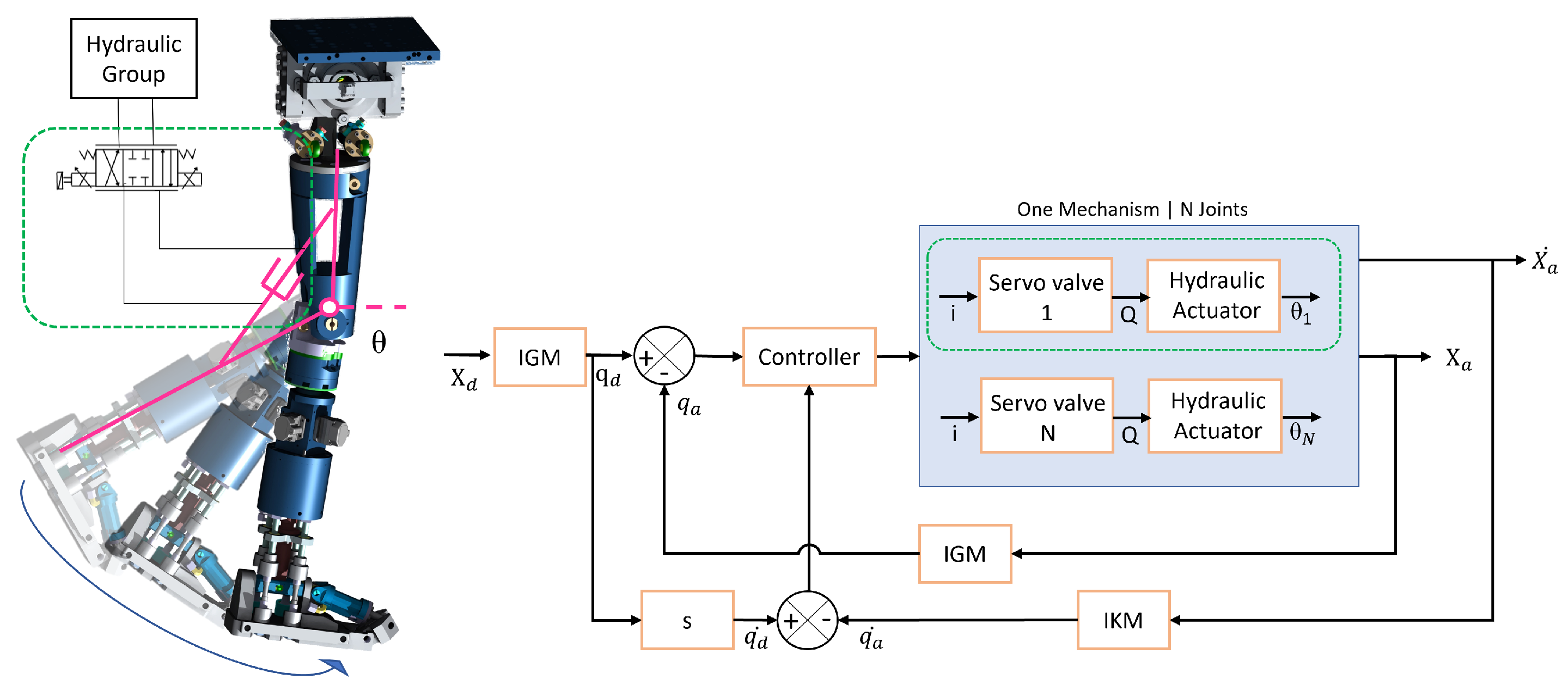
Considering the mechanical design of HYDROïD, there are two existing layers: the joint layer, represented by the servo valve and the hydraulic actuator, and the mechanisms, such as the mechanism of the wrist, ankle, hip, and shoulder. Figure 3 shows an example of HYDROïD’s leg; at the joint level, we have a servo valve that takes current i as input and gives the flow Q as output, leading to a motion of the whole mechanism. The complexity of the control will impact the decisions made in later stages regarding the control architecture. For this purpose, a study is conducted in this section regarding (i) the inverse kinematics and inverse geometry at the ankle mechanism and (ii) the simulation and modeling at the joint level containing a servo valve and rotary hydraulic actuator. This study is beneficial for understanding the complexity and calculating the computational cost for developing the control architecture.

4.1. Kinematic and Inverse Geometric Model of Hybrid Mechanism

The ankle mechanism of HYDROïD is a 3 DoF hybrid mechanism achieved with serial and parallel substructures. The merge of the serial and parallel mechanisms leads to an ankle design that respects the size constraints that do not overload the actuator, producing 3 DoF motion with easy control models. This mechanism is chosen as the case study for two main reasons: (i) this mechanism is considered a complicated mechanism, and (ii) calculating the computation costs of such mechanism is beneficial in designing the control architecture. This section represents the Inverse Geometric Model(IGM) and the Inverse Kinematics Model (IKM) for the ankle mechanism.
The kinematic structure of the ankle mechanism is shown in Figure 4. In the ankle mechanism, there are four closed loops named C h j , and each is composed of the links: C o 1 , C o 2 , C o 3 , C o 1 j , C o 2 j , C o 3 j , C o 4 j , C o 5 j , and C o 6 j with j = 1, 2, 3, 4. There are four linear actuators grouped in couples: the couple ( r 1 1 , r 1 3 ) allows the actuation of the joint q s and the couple ( r 1 2 , r 1 4 ) allows the actuation of the joint q f . The orientation of the end effector with respect to the base is identified with three angles, roll, yaw, and pitch, and grouped in vector X a = ( θ r , θ p , θ y ). The inputs of the hybrid mechanism are the length of the linear actuator r i j and the roll rotation θ r , while the outputs are the angles q v , q s , and q f .

4.1.1. Inverse Geometric Model

The IGM is used to determine the required stroke of the linear actuators. So r 1 j will be calculated for a given posture of the end effector through the IGM. To obtain the IGM of the ankle mechanism, the roll rotation is straightforward since it belongs to the serial part where q v = θ r ; however, for the yaw and pitch, which belong to the parallel mechanism, more calculations are needed, which be presented in this section. Upon the calculations of the IGM, the following notations are adopted:
  • The jth closed kinematic chain is designated as a chain L o o p j for j = 1, 2, 3, 4. The mechanism outputs are grouped into a vector q = ( q s , q f , q v ).
  • The linear joint positions are the mechanism inputs and are named r 1 j for j = 1, 2, 3, 4.
  • The rotation of the ith joint in the jth closed loop is represented by θ i j .
  • All the joints are passive joints except for r 1 j and q v are the active joint variables.
To carry out the IGM, we consider the open mechanism maintained by breaking the z 5 j joints as shown in Figure 4. Hence, the IGM can be presented as follows: For L o o p 1 and L o o p 3 , The rotation of the second and third joints are represented in Equations (1) and (2).
θ 3 j = arcsin ( d · S q v l 3 j )
θ 2 j = arcsin ( ( d · S q s · C q f ) + ( l 4 j · C q s ) l 1 j l 3 j · C 3 j
Hence, the active joint variables are written as in Equation (3),
r 1 j = l 0 l 2 j l 4 j · S q s + d · C q s C q f l 3 j C 2 j C 3 j
Similarly, the same relations are established for L o o p 2 and L o o p 4 . The rotations are shown in Equations (4) and (5).
θ 3 j = arcsin ( d · S q v + l 4 j · C q f l 1 j l 3 j )
θ 2 j = arcsin ( ( d · S q s · C q f ) ( l 4 j · S q s . S q f ) l 3 j · C 3 j )
The active joint variable in these loops is, therefore, presented in Equation (6).
r 1 j = l 0 l 2 j l 4 j · C q s · S q f + d · C q s C q f l 3 j C 2 j C 3 j

4.1.2. Inverse Kinematic Model

Upon calculating the IGM, the calculation of IKM is essential. These models are useful for the simulation of the robot, for the control, and for the motion planning of the robot. Hence, these models will be integrated into the developed control architecture. The IKM is used to determine the relation between the angular velocities around the roll, pitch, and yaw axes grouped in the vector X ˙ a = ( θ r ˙ , θ p ˙ , θ r ˙ ) t and the active joint velocities grouped in the vector r ˙ a = ( r 1 ˙ 1 , r 1 ˙ 2 , r 1 ˙ 3 , r 1 ˙ 4 , r 1 ˙ 5 , q 1 ˙ ) t .
The kinematic model will be expressed as in Equation (7) for the four closed loops. Detailed calculations of the IKM can be found in the Appendix A.
L 4 1 W 1 L 4 1 S q s V 1 0 0 L 4 2 ( C q s W 2 S q s U 2 ) 0 L 4 3 W 3 L 4 3 S q s V 3 0 0 L 4 4 ( C q s W 4 S q s U 4 ) 0 0 0 1 · q ˙ s q ˙ f q ˙ v = W 1 0 W 2 W 3 W 3 0 1 · r 1 ˙ 1 r 1 ˙ 2 r 1 ˙ 3 r 1 ˙ 4 q v ˙
Equation (7) has the classical matrix form shown in Equation (8).
A · q ˙ = B · r ˙
Moreover, the global kinematic variable X ˙ can be written as shown in Equation (9).
X ˙ = q s ˙ Z b + q v ˙ Z v + q f ˙ Z f = q s ˙ S q v + q f ˙ C q v C q s q s ˙ C q v + q f ˙ S q v C q s q v ˙ + q f ˙ S q s = 0 C q v C q s S q v 0 S q v C q s C q v 1 S q s 0 q v ˙ q f ˙ q s ˙
Equation (9) can be reformulated and written as in 10.
X ˙ = D · q ˙
Finally, substituting Equation (10) in Equation (8) results in the final kinematic model of the proposed ankle mechanism, and this is presented in (11).
A · D 1 · X ˙ = B · r ˙

4.2. Modeling and Simulation of Electro-Hydraulic Actuator

The joints of HYDROïD are designed using linear hydraulic actuators [27] or rotary hydraulic actuators with Flapper-Nozzel double-stage servo valves. As rotary actuators are more complex, we will consider them for our study. A study of the servo valve’s dynamic behavior is also considered to improve the dynamic performance and reduce the complexity of the implemented control. An analysis stage is an important stage in determining the influence of the parameters affecting the dynamic performance of the servo valve. This study is indispensable for ensuring the maximum benefit of the servo valve and, therefore, ensuring the best performance of the system, reducing the control algorithm complexity that will be implemented in the control architecture.
This section presents the modeling, simulation, and validation of the mathematical model; the parameters that have the greatest influence on the dynamic performance of the servo valve are also determined. An interpretation of the servo valve’s dynamic behavior is based on determining the stationary error, the damping factor, the natural frequency, the proper frequency, the overshoot, the response time, the transient time, etc.
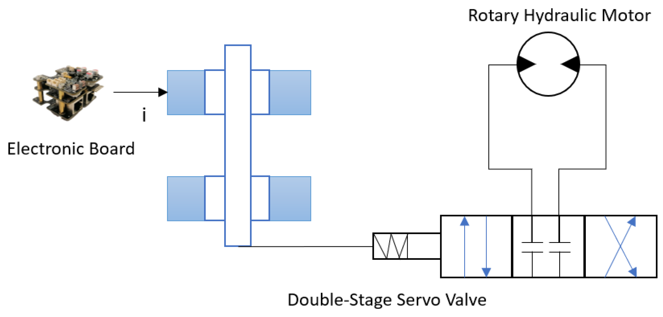
The joint level comprises a double-stage servo valve and a rotating hydraulic motor, as shown in Figure 5. Table 2 presents the notations used throughout this section.
The analysis of the parameters and performance of the dynamic behavior was carried out based on the analysis of the indicial characteristics of speed, acceleration, angular space, moment, power, flow, and pressure. The indicial characteristics were determined based on the indicial functions, whose relationships were established depending on the damping factor for each component, respectively, the servo valve and rotary hydraulic motor. The angular velocity indicial functions were determined taking into account the expression of the transfer function of the rotary hydraulic motor, assimilated with a PT2-type function as in Equation (12). The input is the flow from the servo valve, Q, and the output is the angular velocity of the rotating hydraulic shaft ω .
H ( s ) = ω ( s ) Q ( s ) = a 0 b 2 s 2 + b 1 s + b 0
where the coefficients of the transfer function of the rotary hydraulic motor are represented in Equations (13)–(16).
a 0 = q m ( 1 c f u ) 2 π
b 0 = q m 2 π 2 ( 1 c f u ) + a m b m
b 1 = ( J m + J s ) a m + q m 2 E b m
b 2 = ( J m + J s ) q m 2 E
The parameters of the transfer function, the damping factor, and the natural pulsation are shown in Equation (17).
ξ = b 1 2 b 0 · b 2 ω n = b 0 b 2
For each operating point, the damping factor ξ is determined and compared with the value 1 to establish the slope of the indicial characteristic of the angular velocity ω .
If the damping factor is greater than one, then the response is over-damped. The expression for the angular velocity of the rotary hydraulic motor servo system is shown in Equation (18).
ω 1 = a 0 b 0 · Q current · 1 + b 2 · e b 1 t b 1 b 2 b 1 · e b 2 t b 1 b 2 M f · a m · 1 e b 0 t a m · ( J M + J S ) b 0
If the damping factor is unity, then the response is critically damped, and the expression for the angular velocity of the rotary hydraulic servo system is represented in Equation (19).
ω 2 = a 0 b 0 · Q current · 1 e ω n t · ( 1 ω n t ) M f · a m · 1 e b 0 t a m · ( J M + J S ) b 0
Finally, if the damping factor is less than one, then the response is underdamped, and the expression for the angular velocity of the rotary hydraulic motor is in Equation (20).
ω 3 = a 0 b 0 1 ξ 2 · Q current · 1 e ω n ξ t · sin ω n 1 ξ 2 · t + arctan 1 ξ 2 ξ M f · a m · 1 e b 0 t a m · ( J M + J S ) b 0
Based on the angular velocity calculations, the angular acceleration’s current value is determined in Equation (21).
ϵ current = ω current Δ t
Hence, the current value of the angular space is shown in Equation (22).
θ current = ω current · Δ t 2
Based on the current values of active pressure and the active flow, the current value of active moment and active power are calculated in Equation (23) and in Equation (24):
M a current = q M 2 π · ( p M current p 0 )
N current = p M current · Q current · 0.1
The analysis of the dynamic behavior based on the transfer functions and the inverse Laplace transform was conducted through a program in MatLab—Simulink. Using the mathematical model and after applying the inverse Laplace transform, a proportional type transfer function with second-order inertia (PT2) is obtained for the rotary hydraulic motor and the servo valve.
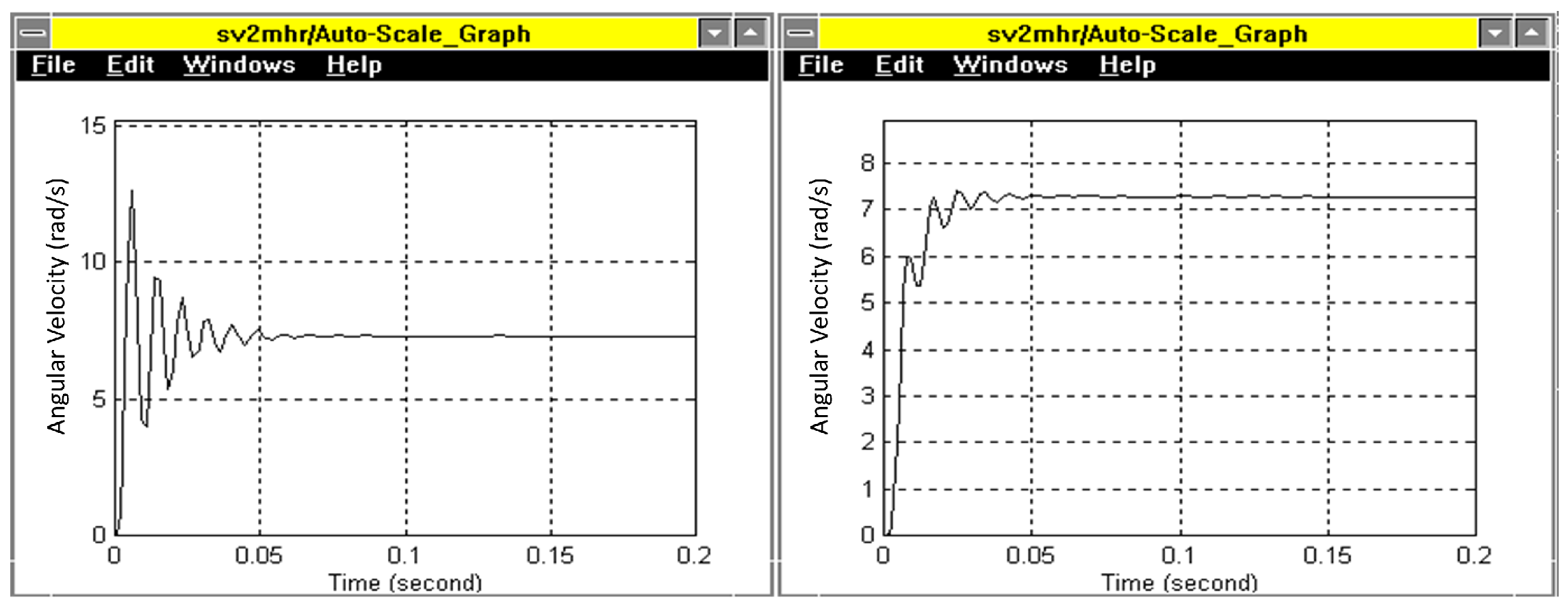
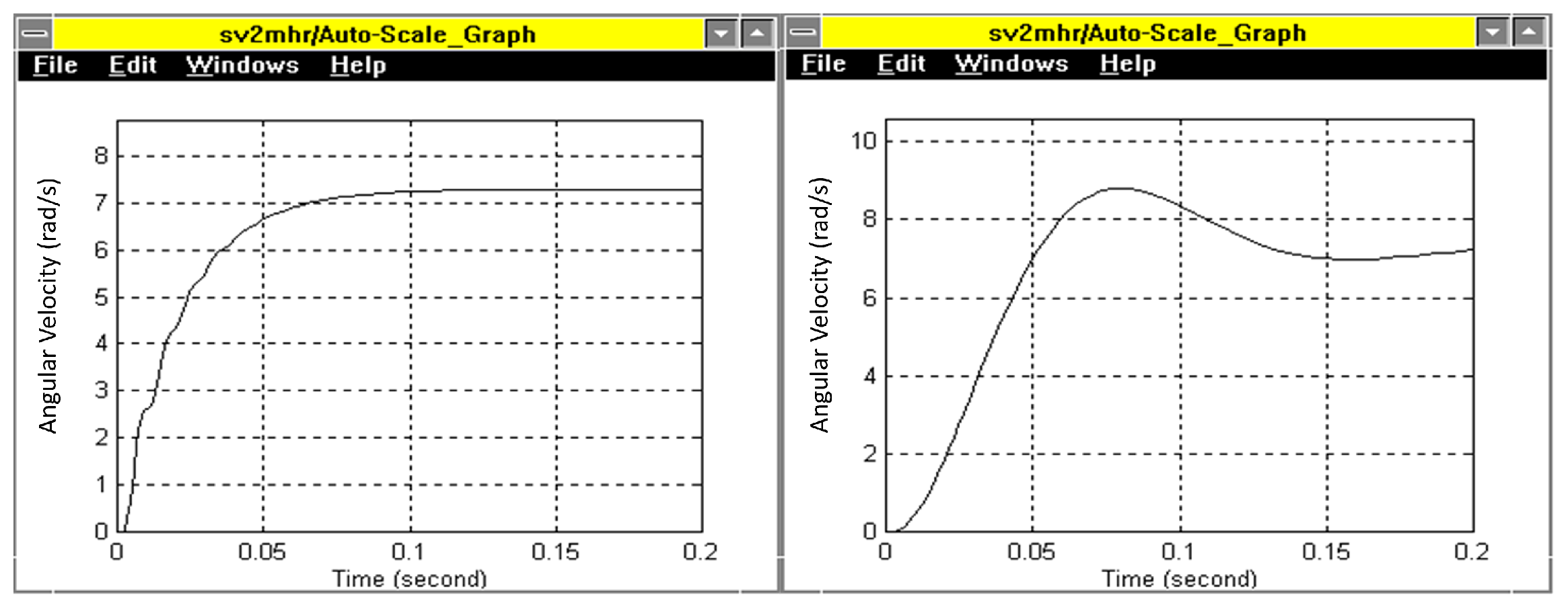
To enhance the performance of the servo valve, a correction was applied, an electronic RC correction with the transfer function of first-order shown Equation (25) with T representing the time constant with a constant value of 0.006 s. The results of this correction are shown in Figure 6. The figure on the left shows the results without correction of the servo system, and the figure on the right shows the results with the corrections included.
H ( s ) = 1 T s + 1
The anticipation correction is also applied using the transfer function in Equation (26). This transfer function is considered a correction of the anticipation in case T d is greater than T i , and otherwise, it is a correction on the inertial. Both corrections were applied with T d equal to 0.01 s and T i equal to 0.001s in case of anticipation correction and with T d equal to 0.0001 s and T i equal to 0.001 s for the inertial correction. The results of these corrections are shown in Figure 7, with the left graph showing the anticipation correction results and the right one showing the graph on the left showing the inertial corrections.
H ( s ) = T d s + 1 T i s + 1
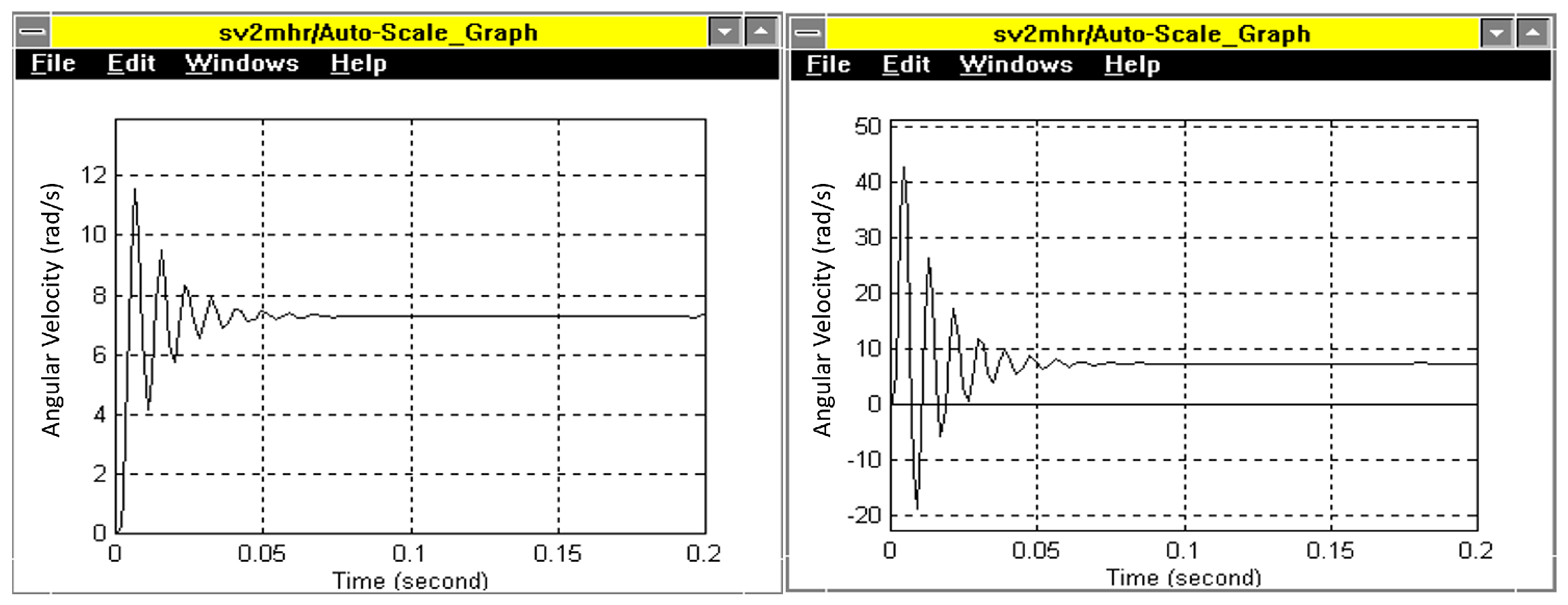
Also, the first-order inertial and the second-order inertial corrections are applied and shown in Figure 8. The left graph shows the results of the first-order correction, and the right graph shows the results of the second-order corrections. The transfer function for the first order is shown in Equation (27) with T i equals 0.02 s, and that of the second order is shown in Equation (28) with T i 1 equals 0.0005 s and T i 2 equals 0.02 s.
H ( s ) = 1 T i s + 1
H ( s ) = 1 T i 2 s 2 + T i 1 s + 1
The following can be observed from the simulation results: (i) first-order inertial correction reduces the overshoot and the transient time but increases the response time, so the operation of the system will be slower; (ii) the anticipation correction increases the overshoot; reduces the response time and increases the transient time, ensuring good promptness so that the system will be fast, accurate, but at the limit of stability; (iii) the second-order inertial correction causes a large delay in the response, introducing a low-frequency vibratory component, it increases the transient time, the operation of the system is transferred to low frequencies so that the response will be prolonged, with oscillations, but the operation is stable.

4.3. Computational Cost Estimations

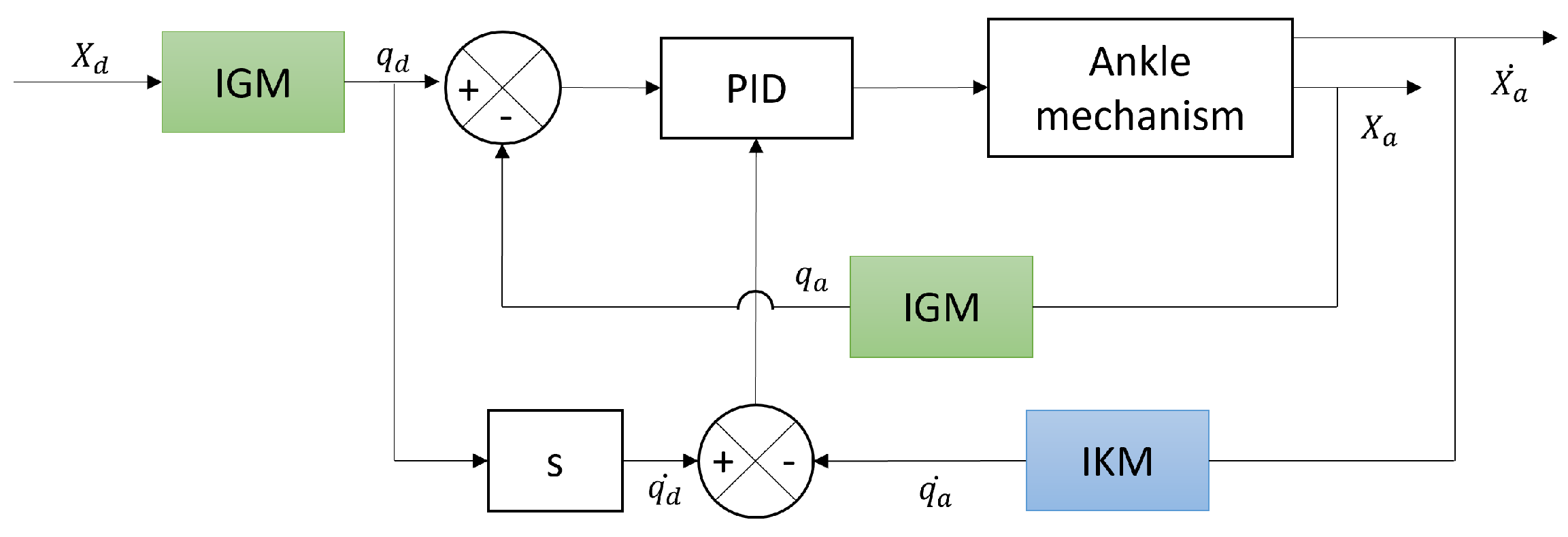
A control loop based on the IGM and the KM could be implemented to control the ankle mechanism. PID controller would also be integrated, as shown in Figure 9. We aim to approximate the computational cost for such a control algorithm to develop an efficient control architecture. For this purpose, we implemented the code for each block on Matlab, estimated the execution time, and calculated the number of executions for each algorithm. The results are shown in Table 3. The execution time is the average time for 100 runs of the algorithm and the number of operations presents the operations presented in the algorithm, such as multiplication, subtraction, addition, and trigonometric functions.
Table 3 shows a rough estimation of the required computations for integrating a control loop in the control architecture. This study is essential for deciding the characteristics of the MCU at the joint level, as the MCU should be capable of handling all these computations in addition to all the computations required for the sensor readings, communication tasks, and any other control task. The utilized MCU at the joint level has a CPU speed of 480 MHz, and it can achieve 1027 DMIPS, meaning that up to 480 million cycles are performed per second and 1027 million instructions can be executed per second. Hence, the MCU can handle the required computations for implementing the control loop for one mechanism, which can be integrated directly into the joint level.

5. Proposed Real-Time Control Architecture

The development of the control architecture of HYDROïD follows a set of specific requirements: (i) achieving high bandwidth in hardware and software, (ii) achieving the deterministic property and having real-time software, (iii) implementing a cost-effective control architecture, (iv) robust and stable distribution of controllers that respects the human-like appearance avoiding the bulky cables, (v) ease of integrating the numerous sensors and actuators, and (vi) respecting the safety factors for the protection of the robot and the human. The proposed control architecture is a distributed, open-source, modular, and real-time architecture to fulfill these requirements. Three main layers represent HYDROïD’s hierarchical architecture: (i) the top layer, the central control unit, (ii) the hardware abstraction layer, and (iii) the lowest layer represented by the firmware of the embedded electronic board on each actuator. This section covers all the necessary selections to develop the control architecture that meets all the requirements.

5.1. Joint Controller

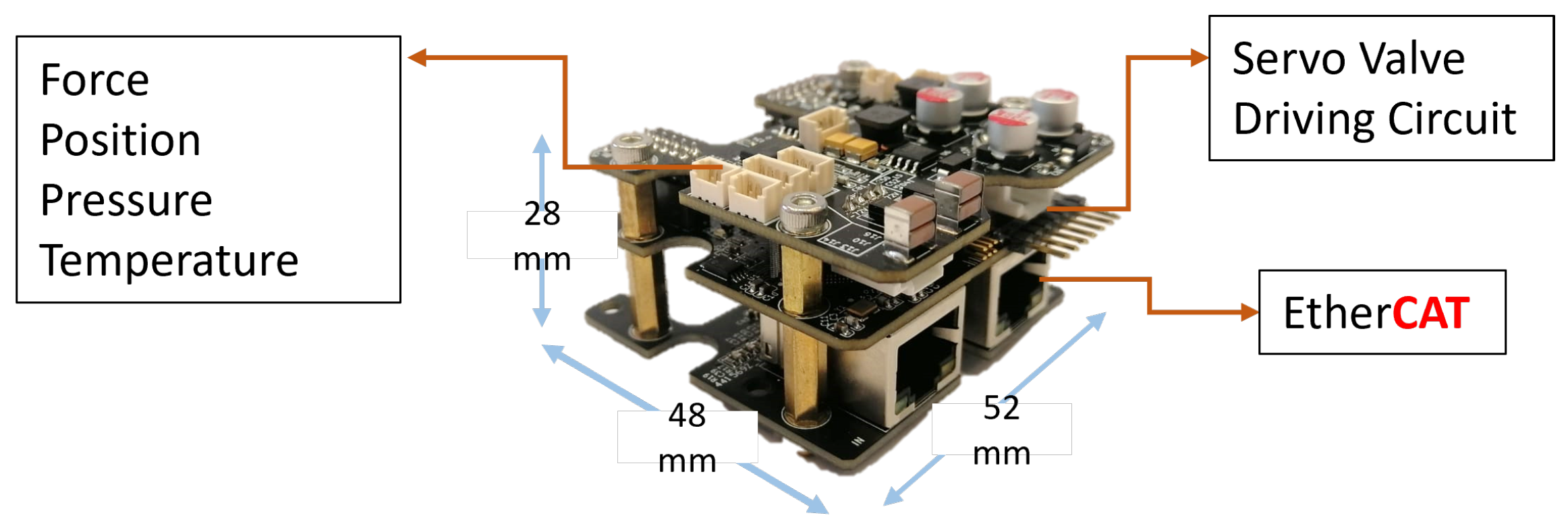
A customized in-house electronic board, shown in Figure 10, is developed on the joint level, represented by SEHA, responsible for controlling the actuator. The compactness of this electronic board is beneficial for the robot’s human-like appearance. The board comprises three different boards. The first is mainly responsible for the power generation of all the actuator sensors besides the sensor’s connectors. The second board consists of (i) the microprocessor STM32H7 that belongs to the cortex M7, which is the highest performance of the member; (ii) the LAN9252, which is the EtherCAT slave with a bandwidth of 100 Mbits/s; (iii) the conditioning circuits for the sensors integrated into the actuator including position, force, pressure, and temperature sensors, (vi) and the driving circuit of the servo valve. The third board contains the EtherCAT ports, ensuring the EtherCAT communication with the main PC.

5.2. Joint Controller Distribution

A distributed control architecture is adopted for the control of HYDROïD. The centralized architecture is inefficient in controlling 36 DoF, requiring many computations. Hence, the distributed approach is chosen. Although the distributed approach is adopted, the joint controller will not be placed on each joint. Having a controller on each joint has the following drawbacks: (i) adding a joint controller on each joint might make the robot bulky without respecting the human appearance; (ii) the hybrid and parallel mechanisms in HYDROïD need synchronization between them to avoid mechanical problems and possible errors. For this purpose, the controllers will be distributed based on the mechanism, with each controller responsible for controlling a specific mechanism. This will result in a total of 15 controllers for the robot. This distribution is presented in Figure 11, highlighting the mechanisms one joint controller will control.

5.3. Communication Protocol

Because a distributed control architecture is utilized, communication between the joint controllers and the central control unit is needed, and the communication protocol selection is essential. The communication protocol ensures the achievement of the bandwidth requirements and the deterministic property. Comparing the different communication protocols, EtherCAT was selected as the communication protocol for data transmission because it shows the best performance besides enabling both hard and soft real-time communication with high bandwidth, leading to an advanced control architecture. This communication protocol is based on the Master-Slave topology. The central control unit layer represents one master device, and the joint controllers represent multiple slave devices. A special EtherCAT configuration is implemented on both levels to identify the master and the slave.

5.4. Real-Time EtherCAT Joint Controller

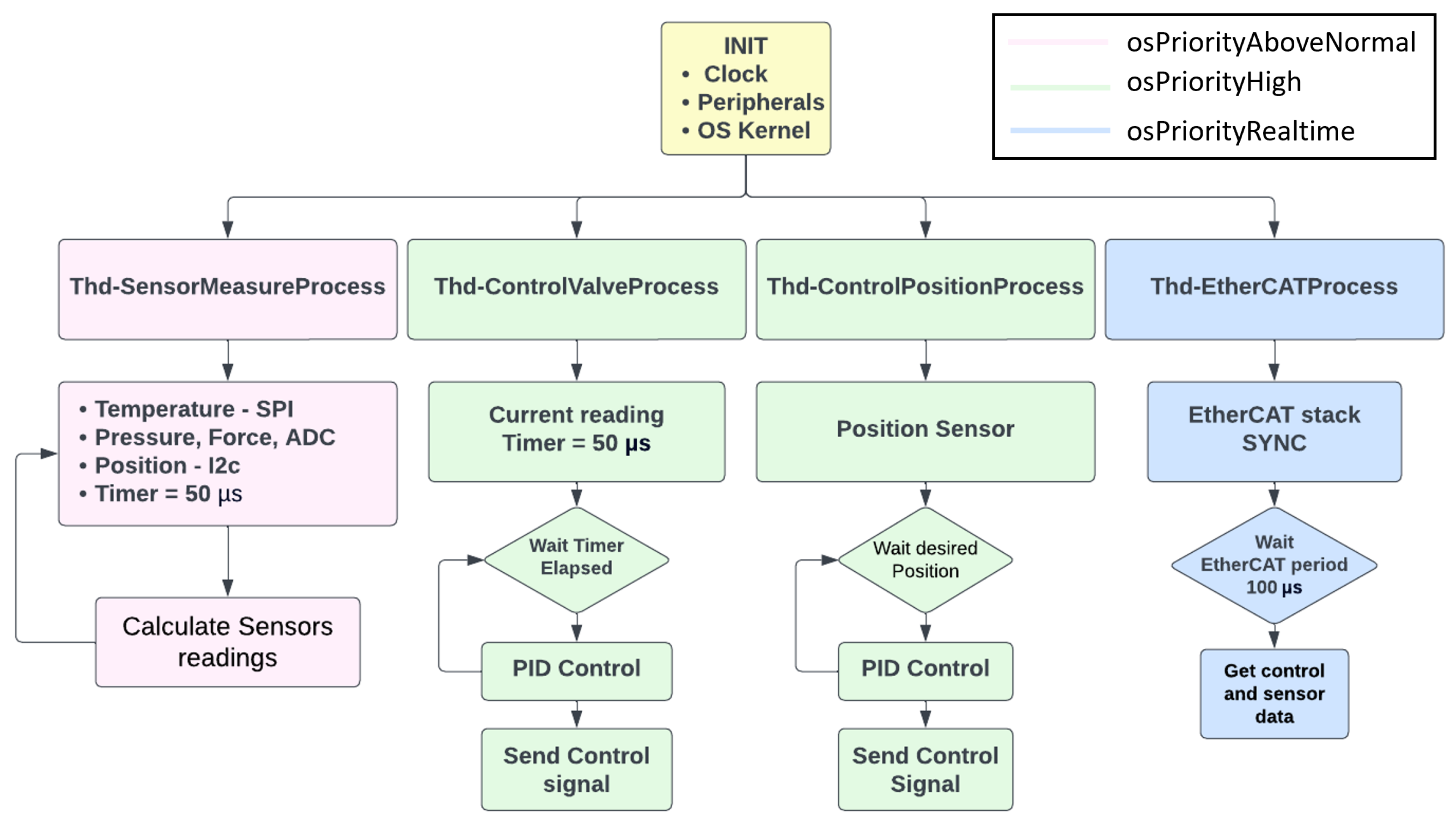
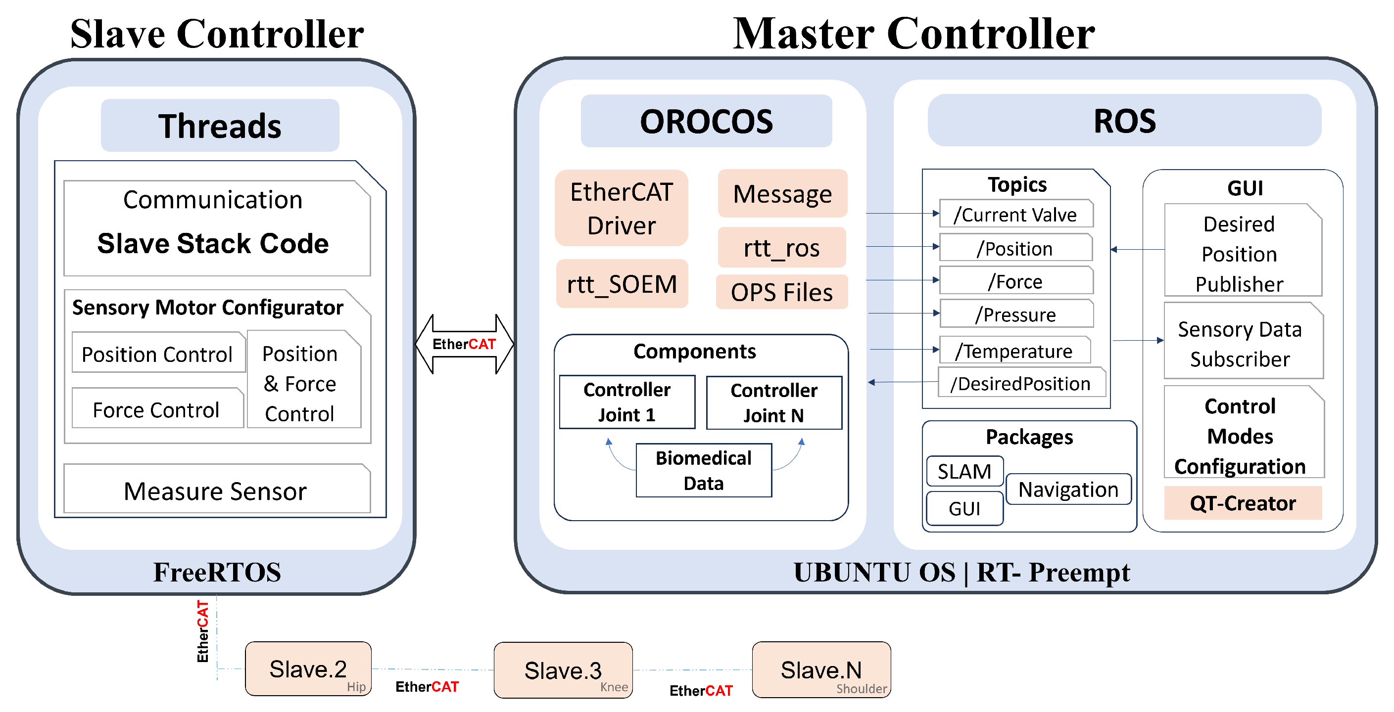
FreeRTOS, an open-source, real-time, and portable firmware for embedded systems, is selected as the firmware for the joint controller. The advantage of FreeRTOS is that it is suited for applications that require soft and hard real-time requirements, and it is cost-effective as it is open-source. It is a real-time kernel on top of which embedded applications can be built to meet the hard real-time requirements. The application will then be organized as a collection of independent threads of execution. We have developed different threads or tasks for the board responsible for controlling the servo valve of SEHA. These are mainly: (i) Thd-SensorMeasurementProcess, which is the thread responsible for all the sensor measurements; (ii) Thd-ControlValveProcess, which is the thread responsible for the current control of the servo valve; (iii) Thd-ControlPositionProcess, which is the process for controlling the position of the servo valve; (iv) lastly, there are the threads responsible for the EtherCAT processing that are Thd-EtherCAT-Sync1-Handle which handles the interrupts of the EtherCAT slave from the SYNC pin of the LAN9252, Thd-EtherCAT-IRQ-Event-Handle which handles the interrupts of the IRQ pin of the LAN9252, and finally the Thd-EtherCAT-Timer-Handle that performs the EtherCAT check operation triggered by a timer. The developed tasks are shown in the Figure 12. The highest priority is given to the communication task to ensure that any interruption from this side is handled directly. Then, the second highest priority is given to the control task, followed by the priority of the sensor readings.
The Slave Stack Code (SSC) tool is utilized to develop the EtherCAT frame structure on the board. The EtherCAT slave device can be configured by the master device using an EtherCAT SubDevice Information (ESI) configuration file, an XML document containing all the information needed to set up a slave device properly for communication. The ESI configuration file for the developed joint controller board is generated using the Slave Stack Code (SSC) tool. The generated file has a special element hierarchy, which describes the slave’s physical properties and the details of the communication protocol. This includes RxPDO and TxPDO elements, representing a single Process Data Object (PDO). PDOs represent the process data exchanged between the master and slave devices of EtherCAT and are updated cyclically. A unique index must define each PDO. The RxPdo elements describe the data transmitted from the slave device to the master device, while the TxPdo elements describe data transmitted from the master device to the slave device. The configured RxPDO and TxPDO for the joint controller of SEHA are shown in Table 4.
288 Bus Variables for communicating the 36 DoF are used. The total size of the TxPDO is 144 bits, and that of the RxPDO is 96. Hence, the total size of the input/output frame is 240 bits for each DoF. The total frame size for controlling the 36 DoF of HYDROïD is 8640 bits or 1080 bytes. Hence, with a link speed of 100 Mbits/s, the simplified theoretical transmission delay is calculated in Equation (29).
τ = 8 x C
This leads to a transmission delay τ equal to 86.4 μ s. To obtain the minimum cycle time, the propagation delays and the latencies within the slave must be added to the transmission delay. According to [28], the minimum achievable cyclic time is calculated as in Equation (30). The notations are shown in Table 5.
Γ = ( 2 n 1 ) + 2 n δ + τ
The typical propagation delay is 0.3 μ s/slave. In EtherCAT communication, a frame is sent by the master, and slaves can read and write data on the fly. The duration of reading or writing operations corresponds only to the network device latency (), independent of frame size, and the same for all slaves. In addition, if we assumed that the network device latency = 0.3 μ s/slave, the minimum cycle time will be around 130 μ s. Hence, this configuration allows the transmission and receipt of data, ideally at approximately 7 kHz. The decision for the proposed control architecture is to operate on 5 kHz, making sure not to exceed the 7 kHz that is allowed and ensuring that if the DoF increases, no losses will occur. These calculations were repeated to further address the adaptability of the developed control architecture, considering that 50 DoF are connected. This resulted in a minimum cycle time of 164.7 μ s, and hence, the transmission and reception of data is allowed at 6 kHz.

5.5. Real-Time Software

On the central control unit, represented by the master PC controlling the robot, a Real-Time Operating System is developed. The selected operating system is Ubuntu, a cost-effective OS that guarantees the software’s real-time performance. Therefore, an RT-preemptible kernel is used to ensure the deterministic property.
Due to the increased complexity of robotic applications, robotics middleware was developed to reduce complexity, improve the software application, and simplify the software design. When using middleware, the development cost will be reduced as the developer will build components representing different parts of the robot and easily integrate these components with other existing components [29]. Among the different existing middleware, OROCOS, a real-time middleware, is used to obtain the hardware abstraction layer with the environment. OROCOS is an open-source middleware that supports four C++ libraries: the Real-Time Toolkit (RTT), the Kinematics and Dynamics Library, the Bayesian Filtering Library, and the OROCOS Component Library [30]. The RTT provides the infrastructure and the functionalities to build robotics applications in real time. It is a component-based tool, and components are connected via defined ports. The port holds a certain message type that could be transmitted using a defined frequency with a big advantage: respecting real-time constraints. This advantage allows the creation of precise control for robotic systems. OROCOS manages the hardware interface between the EtherCAT master and slaves and sends/receives data within specified time boundaries. This hardware interface is developed using the Simple Open Master EtherCAT (SOEM) library, which manages the data transmission using the rtt—soem package. In OROCOS, each EtherCAT hardware requires a specific driver to be developed. It is worth noting that some of the drivers for Beckhoff technology already exist. However, in our case, the driver and its corresponding messages were developed according to the EtherCAT frame of the SEHA controller board. The high-level control is implemented on OROCOS with a period of up to 5 KHz. To take advantage of the large packages available on Robot Operating System (ROS) [31], we designed a mixed hybrid architecture that integrates ROS, enabling hydraulic actuator control through ROS. OROCOS has an integrated interface with the ROS system, which makes it easy to exchange data safely with the ROS system without perturbing real-time performance inside OROCOS. ROS is an open-source middleware that includes many libraries and tools for developing robotic applications. One of the additional advantages of ROS is that it facilitates the integration of our control architecture with other existing robotics systems by developing a bridge and taking advantage of the libraries and the plugins available.
Moreover, to facilitate the usage of the developed control architecture, a Graphical User Interface (GUI) is developed on ROS that integrates the different modes of control, giving the user the ability to switch between these modes easily. Figure 13 shows the implemented software architecture to control HYDROïD.

6. Experimental Validation

The performance of the developed real-time control architecture will be evaluated in three different ways. First, the performance of the joint controller will be evaluated by testing the maximum update rate that the developed board can handle. Second, the performance of the EtherCAT Bus communication is evaluated by testing the network latency. Lastly, the performance of the patched Real-Time Operating System is evaluated by measuring its latency.

6.1. Joint Controller Performance

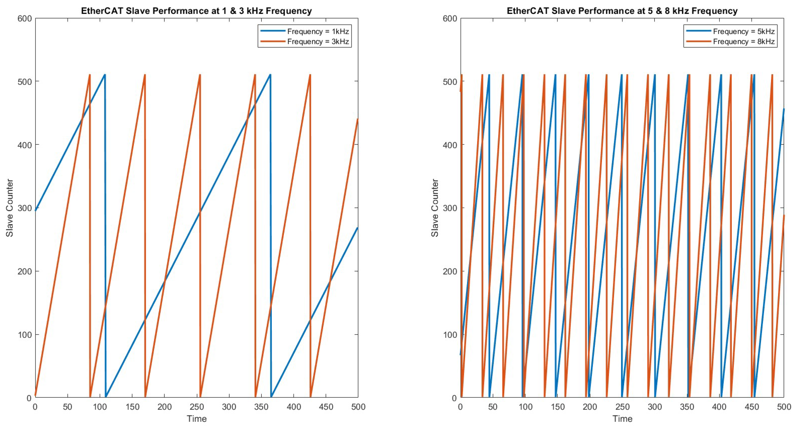
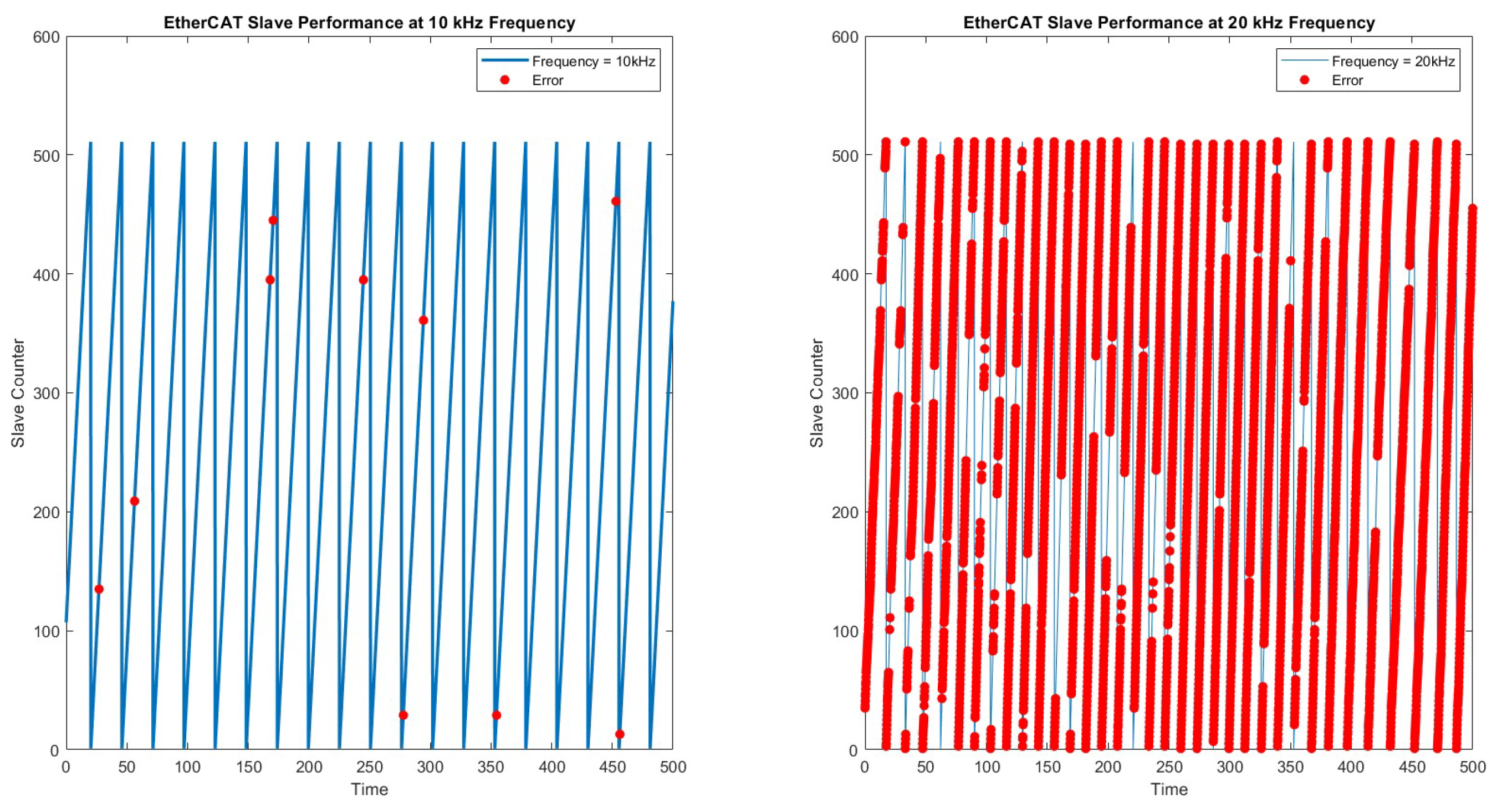
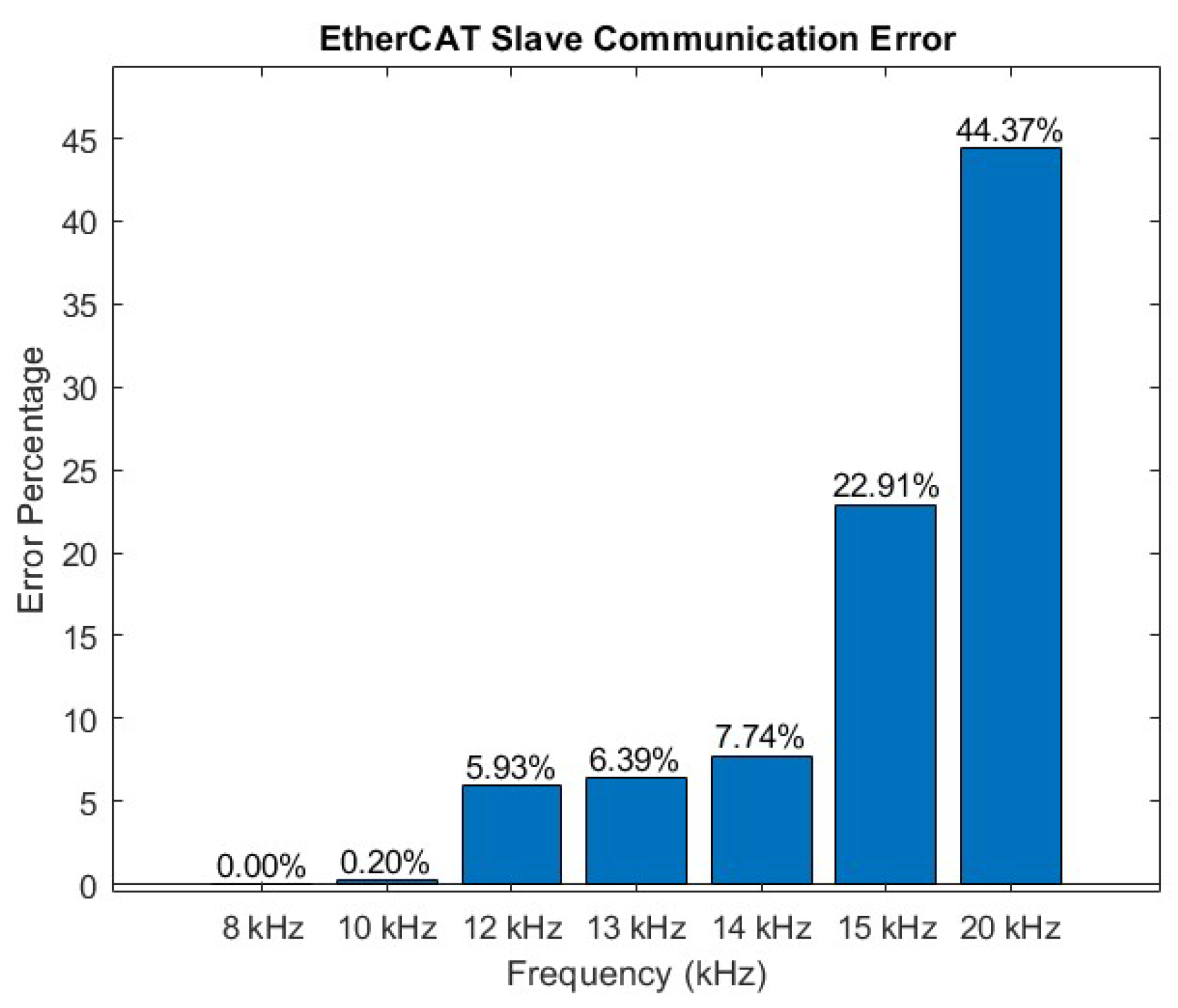
To evaluate the joint controller from the communication perspective, a test was made to check the maximum frequency that could be sent to the EtherCAT slave from the master without losing any frame. Hence, the aim is to check the maximum frequency that could be handled by the EtherCAT slave joint controller without any communication error. For this purpose, a counter was implemented in the EtherCAT slave. A frame is then sent from the master within a specified time, and the counter is updated upon receiving a new frame each time. In case the slave receives a new frame, the counter will be updated. Otherwise, in the case of communication problems where the board cannot receive a new frame within the requested time, the counter will not update, and the same value as the previous counter will be shown. Hence, several frequencies were set from the master, starting from 1 kHz frequency and reaching 20 kHz. For the update rate ranging from 1 kHz to 9 kHz, the results are shown in Figure 14. The counter and the error are plotted, but at these update rates, no errors were detected. However, for the update rates ranging from 10 kHz to 20 kHz, the results are shown in Figure 15; the error is highlighted in red. The board normally operated without communication issues for all the frequencies below 10 kHz. The error percentages are shown in Figure 16; below 10 kHz, the error is 0%, which increases to 0.2% at 10 kHz and to 44.37% at 20 kHz.

6.2. EtherCAT Bus Performance

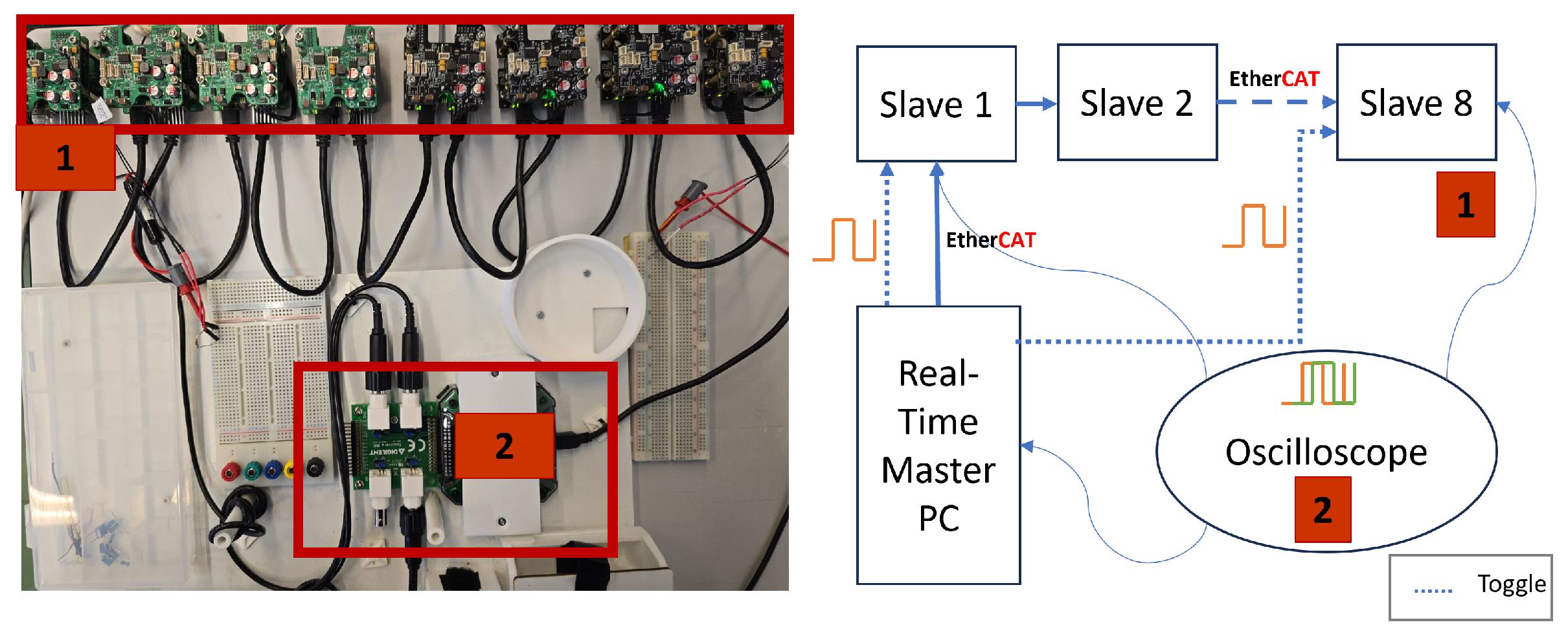
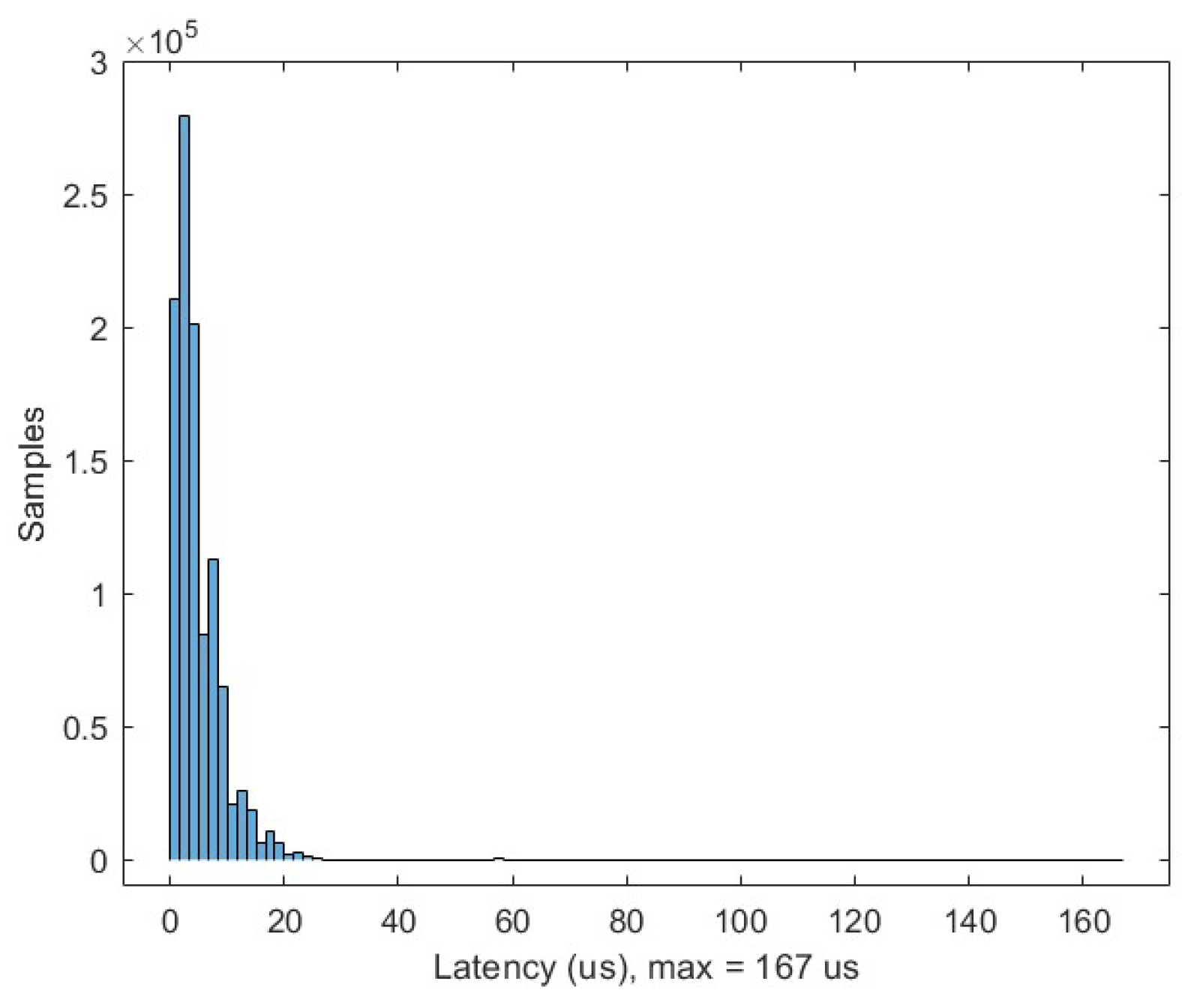
A test was conducted to evaluate the latency in the slave by operating eight slave boards equivalent to controlling the leg of HYDROïD. The network latency represents the delay between the starting execution time of two tasks on the first and last slave in the network. The boards are connected to the master controller. The first board is taken as the reference slave. From the master side, an OROCOS component was developed to toggle the servo valve output of the first and last board. The frequency of the toggle is 5 kHz. An oscilloscope is connected to the first and the last board to measure the output delay. The test was conducted for 65 h. Figure 17 shows the schematics of the conducted experiment. The resulting data shows that the delay did not exceed 167 μ s as shown in Figure 18, which does not exceed the 200 μ s or the 5 kHz.

6.3. Software Performance

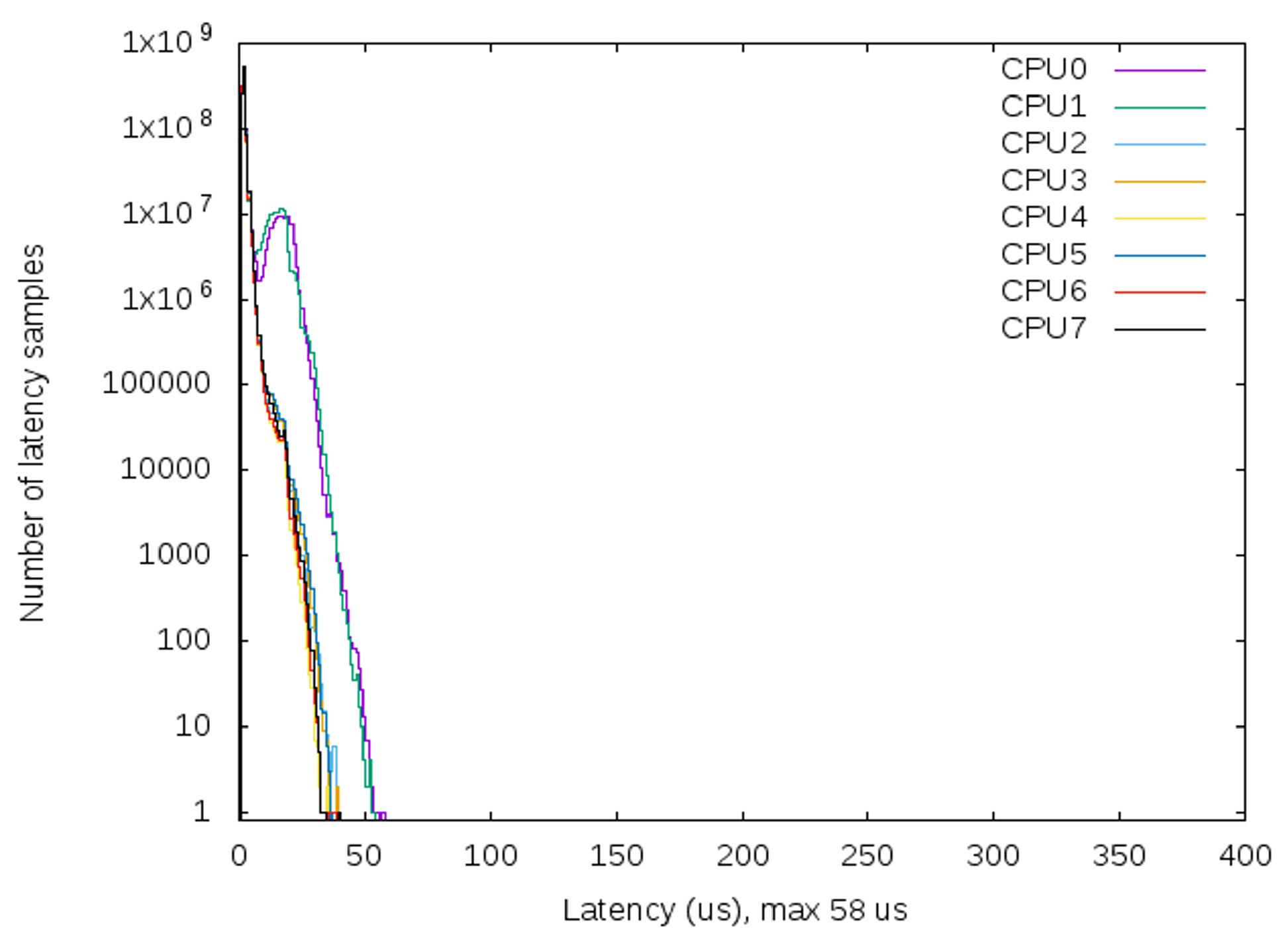
To evaluate the real-time capabilities of the developed real-time software, a cyclic test was performed for 17 h with the entire functioning of the system, besides launching some threads to overcharge the PC, like CPU stress utility, network flood, and graphical stress, to ensure the reliability of the system. The cyclic test is a test that aims to measure the latency of the patched kernel. The latency is the delay before executing the task. This test was conducted twice, one on a standard kernel of Ubuntu without any modifications and the other on the modified kernel. The test on the standard kernel was launched for approximately 3 h, and the latency was 99,577 µs, as shown in Figure 19. However, the latency for the test conducted on the real-time kernel was 58 µs for the operation of 17 h, as shown in Figure 20. The achieved latency in the real-time software assures that our system will not exceed the desired cycle time, 200 μ s equivalent to 5 kHz. Hence, in our proposed solution, the concept of real-time in terms of achieving tasks within a pre-specified time is respected.
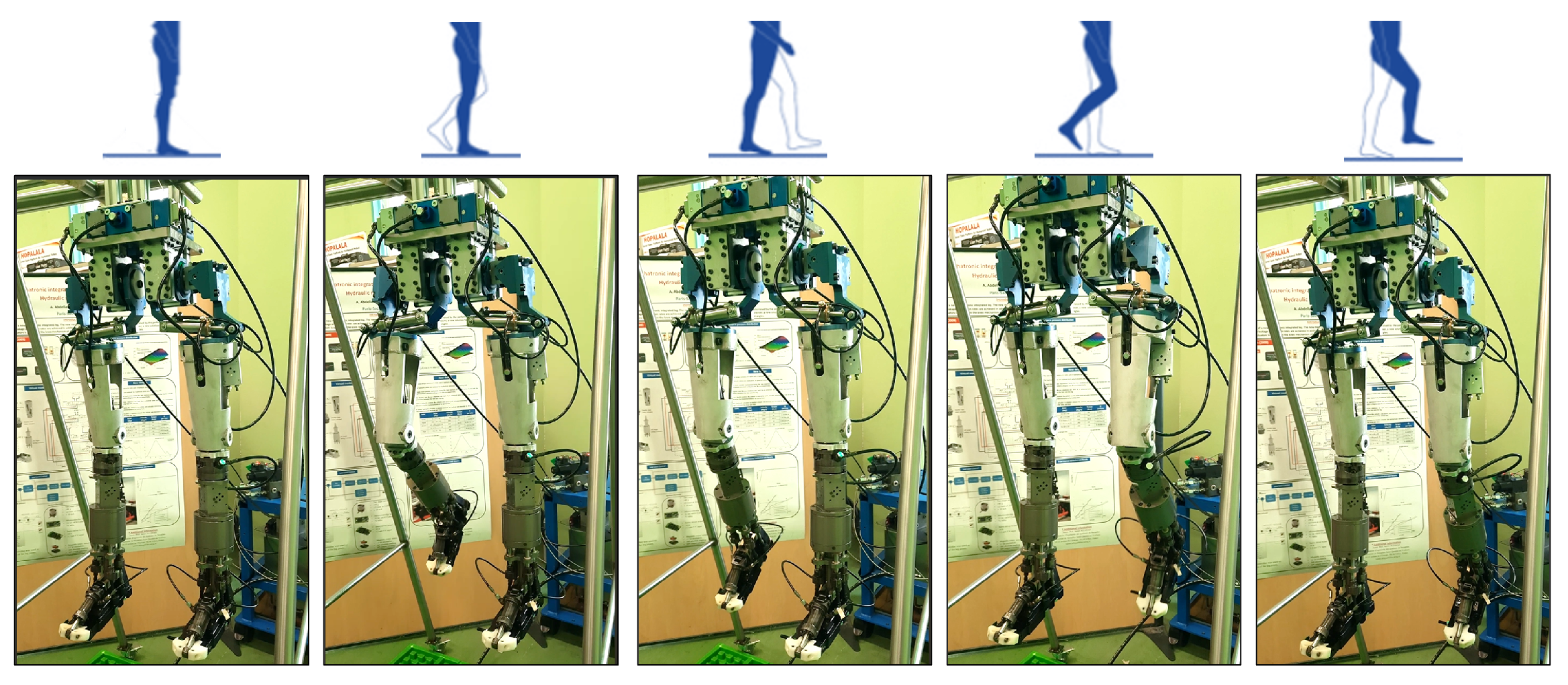
To evaluate the overall performance of the control architecture, a preliminary experiment was conducted directly on HYDROïD by operating four mechanisms: the left and right knee and the right and left hip. The aim was to test the control architecture and the ease of implementing any control algorithm via an experiment to achieve the gate walking cycle through the control of the left and right hip and the left and right knee. The high-level master controller transmits the desired position to achieve the movement based on biomedical data of a healthy person with a 63 cm step length at 100 cm/s velocity, while the low-level joint controller controls the current sent to the servo valve based on the desired position from the high-level controller. Figure 21 shows a snapshot of the robot in operation, and human-like motion was achieved.

7. Conclusions

Hydraulic actuators have proven to be highly effective due to their force capabilities; on the other hand, electrical actuators are useful from the cost perspective and the ease of control. SEHA is a hybrid technology that combines the advantages of the electrical and hydraulic actuators and avoids the disadvantages, leading to a high-performance actuator.
This paper proposes a real-time control architecture for HYDROïD humanoid. The modeling and simulation of one joint of HYDROïD composed of a rotary hydraulic actuator and servo valve were presented and analyzed with the aim of enhancing the performance for developing an efficient control algorithm with reduced complexity. The IGM and the IKM were also calculated and presented, and a rough estimation of the computational cost for implementing a control loop was also conducted to develop an efficient control algorithm. The requirement upon developing the control architecture is to have adaptable software from the perspective that adding sensors and actuators should not be complex. Moreover, the software should ensure the deterministic properties, and hence, there is real-time software for the safe interaction of the robot with its environment. Moreover, high bandwidth is required on both the low-level joint controller and the high-level master controller. Hence, this paper presents a distributed, real-time, and modular control architecture. The proposed architecture is based on EtherCAT communication protocol; the operating system is Ubuntu with a preemptible kernel ensuring the deterministic behavior and a hybrid middleware approach that integrates OROCOS and ROS. The choice of EtherCAT and real-time development is essential for ensuring the safety and stability of the robot, and the hybrid middleware will reduce the complexity of integrating new sensors and actuators, making it an adaptable one.
The results show that (i) the developed in-house board can handle an update rate up to 10 kHz, and communication errors start at 10 kHz. (ii) the network latency while connecting seven boards and operating at 5 kHz did not exceed 167 μ s. (iii) the software latency does not exceed 58 µs, and the deterministic behavior is achieved. Our results show an improvement of 20% for the update rate over those reported by [18], where they achieved a 4 kHz update rate, which is the highest rate according to our knowledge. Also, the results show a reduction by approximately 40% in the control task latency compared to those achieved in [32].
As a future step to achieve the real-time capabilities of the OS, Ubuntu 22.04 will be used. This is the latest version of Ubuntu that offers a real-time kernel. Also, ROS2 [33], the 2nd version of ROS, will be integrated into the system. Moreover, the whole robot will be operated, and the robot’s motion planning will be executed to operate the robot in different environmental setups. Integrating safety algorithms is one of the future works that will be implemented. To further address the safety concerns, the developed control architecture, due to its distributed structure, enables the addition of safety algorithms either on the low-level controller or on the high-level controller on OROCOS or ROS, depending on the algorithm’s requirements.

Author Contributions

Conceptualization, M.G. and S.A.; methodology, M.G. and S.J.; software, M.G. and S.J.; validation, M.G.; formal analysis, M.G. and S.J.; investigation, M.G.; resources, M.G. and N.A.O.; data curation, M.G.; writing—original draft preparation, M.G.; writing—review and editing, S.A., N.A.O. and S.O.; visualization, M.G. and S.O.; supervision, S.A. and N.A.O.; project administration, S.A.; funding acquisition, S.A. All authors have read and agreed to the published version of the manuscript.

Funding

This research was funded by KALYSTA Actuation Company and the industrial excellence chair between the University of Evry and Kalysta Actuation.

Data Availability Statement

The raw data supporting the conclusions of this article will be made available by the authors on request.

Conflicts of Interest

The authors declare no conflicts of interest.

Appendix A. Detailed Calculation of IKM

Using the kinematic composition formula, the kinematic of the jth closed loop can be described as in Equation (A1). Where T c S p / S b is the kinematic wrench of the foot relative to the base of the parallel mechanism, T c S 1 / S b j is the kinematic wrench of the foot relative to the base of the parallel mechanism, T c S 2 / S 1 j is the kinematic wrench of the jth cable relative to the jth linear actuator, and T c S p / S 2 j is the kinematic wrench of the foot relative to the jth cable.
T c S p / S b = T c S 1 / S b j + T c S 2 / S 1 j + T c S p / S 2 j
This relation is expressed with the individual screws as shown in Equation (A2). With θ ˙ i j representing the derivative of θ i j and $ k j is the kinematic screw of the kth joint in the jth closed chain.
T c S p / S b = r ˙ 1 j $ 1 j + θ ˙ 2 j $ 2 j + θ ˙ 3 j $ 3 j + θ ˙ 4 j $ 4 j + θ ˙ 5 j $ 5 j + θ ˙ 6 j $ 6 j + θ ˙ 7 j $ 7 j
Since r 1 j is the active variable in the closed chain, we can define the reciprocal screw of this variable named $ 1 R j that satisfies the condition in Equation (A3)
$ i j $ 1 R j = 0 , i = 2 , 3 , 4 , 5 , 6 , 7
The frame R 1 j placed on O 1 j and parallel to R b is chosen as the working reference frame for each closed chain. The jth cable projected in this frame can be written with the coordinates as in Equation (A4).
A j O 1 j = U j V j W j R 1 j
Solving Equation (A3) will result in the desired screw shown in Equation (A5).
$ 1 R j = 1 U j 2 + V j 2 + W j 2 [ U j V j W j 0 0 0 ]
Multiplying Equation (A5) by Equation (A2) and choosing A j , shown in Equation (A1), as the working point for the j t h closed chain, the determined relation is shown in Equation (A6).
$ 1 R j T c S p / S b ( A j ) = r ˙ 1 j $ 1 j $ 1 R j
The kinematic wrench of the foot relative to the base S b project on R b is written in Equation (A7).
T c S p / S b ( A 0 ) = q ˙ s z s + q ˙ f z f = q ˙ f C q s q ˙ s q ˙ f S q s
Because of the hybrid mechanism, the first rotation joint is q v independent of the two other joints q s and q f . Therefore, replacing Equations (A5) and (A7) in Equation (A6) for the four closed loops, the kinematic model will be expressed as in Equation (A8).
L 4 1 W 1 L 4 1 S q s V 1 0 0 L 4 2 ( C q s W 2 S q s U 2 ) 0 L 4 3 W 3 L 4 3 S q s V 3 0 0 L 4 4 ( C q s W 4 S q s U 4 ) 0 0 0 1 · q ˙ s q ˙ f q ˙ v = W 1 0 W 2 W 3 W 3 0 1 · r 1 ˙ 1 r 1 ˙ 2 r 1 ˙ 3 r 1 ˙ 4 q v ˙

References

  1. Ibrahim, A.A.H.; Ammounah, A.; Alfayad, S.; Tliba, S.; Ouezdou, F.B.; Delaplace, S. Hydraulic Robotic Leg for HYDROïD Robot: Modeling and Control. J. Robot. Mechatron. 2022, 34, 576–587. [Google Scholar] [CrossRef]
  2. Alfayad, S.; Kardofaki, M.; Sleiman, M. Hydraulic Actuator with Overpressure Compensation. WO Patent WO2020173933A1, 3 September 2020. [Google Scholar]
  3. Fischmeister, S.; Lam, P. Time-Aware Instrumentation of Embedded Software. IEEE Trans. Ind. Inform. 2010, 6, 652–663. [Google Scholar] [CrossRef]
  4. Gouaillier, D.; Hugel, V.; Blazevic, P.; Kilner, C.; Monceaux, J.; Lafourcade, P.; Marnier, B.; Serre, J.; Maisonnier, B. Mechatronic design of NAO humanoid. In Proceedings of the 2009 IEEE International Conference on Robotics and Automation, Kobe, Japan, 12–17 May 2009; pp. 769–774. [Google Scholar] [CrossRef]
  5. Kaneko, K.; Kaminaga, H.; Sakaguchi, T.; Kajita, S.; Morisawa, M.; Kumagai, I.; Kanehiro, F. Humanoid Robot HRP-5P: An Electrically Actuated Humanoid Robot with High-Power and Wide-Range Joints. IEEE Robot. Autom. Lett. 2019, 4, 1431–1438. [Google Scholar] [CrossRef]
  6. Nelson, G.; Saunders, A.; Neville, N.; Swilling, B.; Bondaryk, J.; Billings, D.; Lee, C.; Playter, R.; Raibert, M. PETMAN: A Humanoid Robot for Testing Chemical Protective Clothing. J. Robot. Soc. Jpn. 2012, 30, 372–377. [Google Scholar] [CrossRef]
  7. Radford, N.A.; Strawser, P.; Hambuchen, K.; Mehling, J.S.; Verdeyen, W.K.; Donnan, A.S.; Holley, J.; Sanchez, J.; Nguyen, V.; Bridgwater, L.; et al. Valkyrie: NASA’s First Bipedal Humanoid Robot. J. Field Robot. 2015, 32, 397–419. [Google Scholar] [CrossRef]
  8. Sygulla, F.; Wittmann, R.; Seiwald, P.; Berninger, T.; Hildebrandt, A.; Wahrmann, D.; Rixen, D. An EtherCAT-Based Real-Time Control System Architecture for Humanoid Robots. In Proceedings of the 2018 IEEE 14th International Conference on Automation Science and Engineering (CASE), Munich, Germany, 20–24 August 2018; pp. 483–490. [Google Scholar] [CrossRef]
  9. Akachi, K.; Kaneko, K.; Kanehira, N.; Ota, S.; Miyamori, G.; Hirata, M.; Kajita, S.; Kanehiro, F. Development of humanoid robot HRP-3P. In Proceedings of the 5th IEEE-RAS International Conference on Humanoid Robots, San Diego, CA, USA, 5–7 December 2005; pp. 50–55. [Google Scholar] [CrossRef]
  10. Cereia, M.; Bertolotti, I.C.; Scanzio, S. Performance of a Real-Time EtherCAT Master Under Linux. IEEE Trans. Ind. Inform. 2011, 7, 679–687. [Google Scholar] [CrossRef]
  11. Park, I.W.; Kim, J.Y.; Lee, J.; Oh, J.H. Mechanical design of humanoid robot platform KHR-3 (KAIST Humanoid Robot 3: HUBO). In Proceedings of the 5th IEEE-RAS International Conference on Humanoid Robots, Tsukuba, Japan, 5 December 2005; pp. 321–326. [Google Scholar] [CrossRef]
  12. Park, I.W.; Kim, J.Y.; Park, S.W.; Oh, J.H. Development of humanoid robot platform KHR-2 (KAIST humanoid robot-2). In Proceedings of the 4th IEEE/RAS International Conference on Humanoid Robots, Santa Monica, CA, USA, 10–12 November 2004; Volume 1, pp. 292–310. [Google Scholar] [CrossRef]
  13. Cena, G.; Seno, L.; Valenzano, A.; Vitturi, S. Performance analysis of Ethernet Powerlink networks for distributed control and automation systems. Comput. Standards Interfaces 2009, 31, 566–572. [Google Scholar] [CrossRef]
  14. Jansen, D.; Buttner, H. Real-time Ethernet: The EtherCAT solution. Comput. Control Eng. 2004, 15, 16–21. [Google Scholar] [CrossRef]
  15. Nelson, G.; Saunders, A.; Playter, R. The PETMAN and Atlas Robots at Boston Dynamics. In Humanoid Robotics: A Reference; Springer: Dordrecht, The Netherlands, 2019; pp. 169–186. [Google Scholar] [CrossRef]
  16. Stasse, O.; Flayols, T.; Budhiraja, R.; Giraud-Esclasse, K.; Carpentier, J.; Mirabel, J.; Del Prete, A.; Souères, P.; Mansard, N.; Lamiraux, F.; et al. TALOS: A new humanoid research platform targeted for industrial applications. In Proceedings of the 2017 IEEE-RAS 17th International Conference on Humanoid Robotics (Humanoids), Birmingham, UK, 15–17 November 2017; pp. 689–695. [Google Scholar] [CrossRef]
  17. Kaminaga, H.; Ko, T.; Masumura, R.; Komagata, M.; Sato, S.; Yorita, S.; Nakamura, Y. Mechanism and Control of Whole-Body Electro-Hydrostatic Actuator Driven Humanoid Robot Hydra. In Proceedings of the 2016 International Symposium on Experimental Robotics, Nagasaki, Japan, 3–8 October 2016; Kulić, D., Nakamura, Y., Khatib, O., Venture, G., Eds.; Springer: Cham, Switzerland, 2017; pp. 656–665. [Google Scholar] [CrossRef]
  18. Ahn, J.; Park, S.; Sim, J.; Park, J. Dual-Channel EtherCAT Control System for 33-DOF Humanoid Robot TOCABI. IEEE Access 2023, 11, 44278–44286. [Google Scholar] [CrossRef]
  19. Ferrati, M.; Settimi, A.; Muratore, L.; Cardellino, A.; Rocchi, A.; Mingo Hoffman, E.; Pavan, C.; Kanoulas, D.; Tsagarakis, N.G.; Natale, L.; et al. The Walk-Man Robot Software Architecture. Front. Robot. AI 2016, 3, 25. [Google Scholar] [CrossRef]
  20. Nori, F.; Traversaro, S.; Eljaik, J.; Romano, F.; Del Prete, A.; Pucci, D. iCub Whole-Body Control through Force Regulation on Rigid Non-Coplanar Contacts. Front. Robot. AI 2015, 2, 6. [Google Scholar] [CrossRef]
  21. Stasse, O.; Flayols, T. An Overview of Humanoid Robots Technologies. In Biomechanics of Anthropomorphic Systems; Venture, G., Laumond, J.P., Watier, B., Eds.; Springer Tracts in Advanced Robotics; Springer International Publishing: Cham, Switzerland, 2019; Volume 124, pp. 281–310. [Google Scholar] [CrossRef]
  22. Karumanchi, S.; Edelberg, K.; Baldwin, I.; Nash, J.; Reid, J.; Bergh, C.; Leichty, J.; Carpenter, K.; Shekels, M.; Gildner, M.; et al. Team RoboSimian: Semi-autonomous Mobile Manipulation at the 2015 DARPA Robotics Challenge Finals. J. Field Robot. 2017, 34, 305–332. [Google Scholar] [CrossRef]
  23. Asfour, T.; Waechter, M.; Kaul, L.; Rader, S.; Weiner, P.; Ottenhaus, S.; Grimm, R.; Zhou, Y.; Grotz, M.; Paus, F. ARMAR-6: A High-Performance Humanoid for Human-Robot Collaboration in Real-World Scenarios. IEEE Robot. Autom. Mag. 2019, 26, 108–121. [Google Scholar] [CrossRef]
  24. Ammounah, A. Architecture de Contrôle pour un robot Humanoïde à Actionnement Hydraulique. Ph.D. Thesis, Université Paris-Saclay, Paris, France, 2021. [Google Scholar]
  25. Alfayad, S.; Tayba, A.M.; Ouezdou, F.B.; Namoun, F. Kinematic Synthesis and Modeling of a Three Degrees-of-Freedom Hybrid Mechanism for Shoulder and Hip Modules of Humanoid Robots. J. Mech. Robot. 2016, 8, 041017. [Google Scholar] [CrossRef]
  26. Abdellatif Hamed Ibrahim, A.; Alfayad, S.; Hildebrandt, A.C.; Ouezdou, F.; Mechbal, N.; Zweiri, Y. Development of a New Hydraulic Ankle for HYDROïD Humanoid Robot. J. Intell. Robot. Syst. 2018, 92, 293–308. [Google Scholar] [CrossRef]
  27. Alfayad, S.; Kardofaki, M.; Sleiman, M.; Arlot, R. Verin a Capteur de Position Integre. WO Patent WO2023088972A1, 25 May 2023. [Google Scholar]
  28. Robert, J.; Georges, J.P.; Rondeau, E.; Divoux, T. Minimum Cycle Time Analysis of Ethernet-Based Real-Time Protocols. Int. J. Comput. Commun. Control 2012, 7, 743–757. [Google Scholar] [CrossRef]
  29. Elkady, A.; Sobh, T. Robotics Middleware: A Comprehensive Literature Survey and Attribute-Based Bibliography. J. Robot. 2012, 2012, 959013. [Google Scholar] [CrossRef]
  30. Bruyninckx, H. Open robot control software: The OROCOS project. In Proceedings of the 2001 ICRA—IEEE International Conference on Robotics and Automation (Cat. No.01CH37164), Seoul, Republic of Korea, 21–26 May 2001; Volume 3, pp. 2523–2528. [Google Scholar] [CrossRef]
  31. Quigley, M.; Gerkey, B.; Conley, K.; Faust, J.; Foote, T.; Leibs, J.; Berger, E.; Wheeler, R.; Ng, A. ROS: An open-source Robot Operating System. In Proceedings of the ICRA Workshop on Open Source Software, Kobe, Japan, 12–17 May 2009. [Google Scholar]
  32. Puck, L.; Keller, P.; Schnell, T.; Plasberg, C.; Tanev, A.; Heppner, G.; Roennau, A.; Dillmann, R. Performance Evaluation of Real-Time ROS2 Robotic Control in a Time-Synchronized Distributed Network. In Proceedings of the 2021 IEEE 17th International Conference on Automation Science and Engineering (CASE), Lyon, France, 23–27 August 2021; pp. 1670–1676. [Google Scholar] [CrossRef]
  33. Macenski, S.; Foote, T.; Gerkey, B.; Lalancette, C.; Woodall, W. Robot Operating System 2: Design, Architecture, and Uses in the Wild. Sci. Robot. 2022, 7, eabm6074. [Google Scholar] [CrossRef] [PubMed]
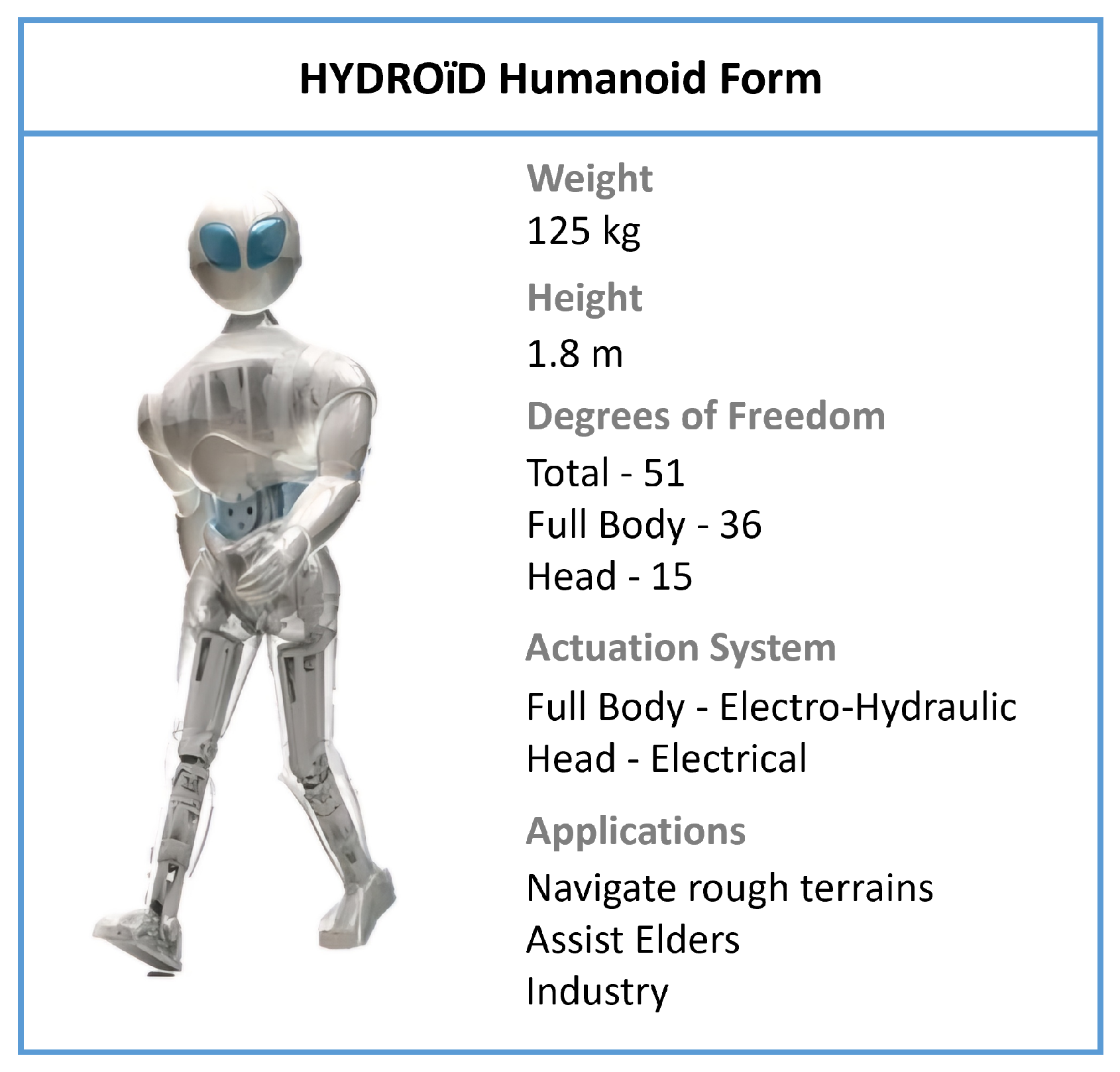
Figure 1. HYDROïD humanoid general description.
Mathematics 12 01405 g001
Figure 2. HYDROïD ’s kinematic structure.
Mathematics 12 01405 g002
Figure 3. Control of one mechanism in HYDROïD.
Mathematics 12 01405 g003
Figure 4. Kinematic structure of HYDROïD’s ankle mechanism.
Mathematics 12 01405 g004
Figure 5. Simplified schematic of the robot’s joint level composed of a double-stage servo valve, hydraulic rotating motor, and an electronic board.
Mathematics 12 01405 g005
Figure 6. Rotary hydraulic actuator with a servo valve simulation results, the graph on the left is without the servo valve correction there is an overshoot, the graph on the right is with the servo valve correction included with T = 0.006 s, the overshoot is reduced and the response time is increased.
Mathematics 12 01405 g006
Figure 7. Rotary hydraulic actuator with a servo valve simulation results with anticipation and inertial correction of the servo valve, the graph on the left is with inertial correction with T d = 0.0001 and T i = 0.001, the overshoot increased and the response time decreased, and the graph on the right is with anticipation correction with T d = 0.01 and T i = 0.001 the overshoot increased, the response time decreased and the transient time increased.
Mathematics 12 01405 g007
Figure 8. Rotary hydraulic actuator with a servo valve simulation results with inertial correction of the servo valve, the graph on the left is with first-order inertial correction included with T i = 0.02 sec the overshoot is reduced, but the response time is increased, and the graph on the right is with second-order inertial correction with T i 2 = 0.0005 s and T i 1 = 0.02 s, a large response time is introduced and the transient time is increased but operation is stable.
Mathematics 12 01405 g008
Figure 9. Control loop using the IGM and the KM model.
Mathematics 12 01405 g009
Figure 10. Developed electronic board at the joint level.
Mathematics 12 01405 g010
Figure 11. Distribution of the joint controllers of HYDROïD upon mechanism.
Mathematics 12 01405 g011
Figure 12. Developed tasks for the joint controller.
Mathematics 12 01405 g012
Figure 13. Developed control architecture for HYDROïD’s control.
Mathematics 12 01405 g013
Figure 14. EtherCAT Slave performance at update rate ranging from 1 kHz to 9 kHz, the slave is operating normally, and all the frames are received with no errors.
Mathematics 12 01405 g014
Figure 15. EtherCAT Slave performance from 10 kHz to 20 kHz, errors, highlighted in red, start to occur and increase with increasing the update rate.
Mathematics 12 01405 g015
Figure 16. Error percentage at EtherCAT slave among different update rates.
Mathematics 12 01405 g016
Figure 17. Conducted test for evaluating network latency.
Mathematics 12 01405 g017
Figure 18. Latency on the slave joint controller-max latency = 167 μ s.
Mathematics 12 01405 g018
Figure 19. Latency of standard Ubuntu kernel.
Mathematics 12 01405 g019
Figure 20. Latency of real-time Ubuntu kernel.
Mathematics 12 01405 g020
Figure 21. HYDROïD in operation applying the proposed control architecture.
Mathematics 12 01405 g021
Table 1. Representation of HYDROïD’s DoF.
MechanismDoF/MechanismQuantityTotal DoF
Toe122
Ankle326
Knee122
Hip326
Torso414
Shoulder428
Elbow122
Wrist326
36
Table 2. Terms, Notation, and Units.
TermsNotationUnits
Geometric capacity of engine q m cm3
Gradient of flow losses proportional to the pressure in the engine a m cm5/daNs
Reduced moment of inertia at the shaft of rotating hydraulic motor J r daNcms2/rad
Moment of inertia at the motor J M daNcms2/rad
Moment of inertia at the stator J s daNcms2/rad
Resisting moment M r daNcm
Moment of friction M f daNcms
Gradient of moment losses proportional to angular velocity b m daNcms/rad
Dry friction coefficient c f u -
Angular speed of the rotating hydraulic motor shaft ω rad/s
Modulus of elasticity of oilEdaN/cm2
Damping factor ξ -
Natural pulsation ω n rad/s
Current output flow from servo valve Q c u r r e n t cm3/s
Angular acceleration ϵ rad/s2
Angular space θ rad
Active moment M a daNcm
Active powerNW
Active pressure p M daN/cm2
Pressure on discharge path p 0 daN/cm2
Table 3. Estimation of the control loop computation costs.
AlgorithmNumber of OperationsExecution Time (ms)
IGM525.3
IKM15015.4
PID154.6
Table 4. PDO mapping of the EtherCAT frame.
PDOObjectData TypeIndex
RxPDOIndexUint320x1600
Data1Uint320x1600
Data2Uint320x1600
Total bits96 bits
TxPDOValve CurrentUint320x1A00
TemperatureUint320x1A00
PositionUint320x1A00
ForceUint320x1A00
System StateUint160x1A00
Total bits144 bits
Table 5. Terms, Notation, and Units.
TermsNotationUnits
Minimum cycle time Γ s
Transmission delay τ s
Network device latencys
Propagation delay δ s
Link capacityCbits/s
Payloadxbytes
Number of network devices (slaves)n
Disclaimer/Publisher’s Note: The statements, opinions and data contained in all publications are solely those of the individual author(s) and contributor(s) and not of MDPI and/or the editor(s). MDPI and/or the editor(s) disclaim responsibility for any injury to people or property resulting from any ideas, methods, instructions or products referred to in the content.