Article

Towards Molecularly Imprinted Polypyrrole-Based Sensor for the Detection of Methylene Blue

by
Raimonda Boguzaite
1,
Greta Pilvenyte
1,
Vilma Ratautaite
1,*,
Ernestas Brazys
2,
Almira Ramanaviciene
3 and
Arunas Ramanavicius
1,2,*
1
Department of Nanotechnology, State Research Institute Center for Physical Sciences and Technology (FTMC), Sauletekio Av. 3, LT-10257 Vilnius, Lithuania
2
Department of Physical Chemistry, Institute of Chemistry, Faculty of Chemistry and Geosciences, Vilnius University (VU), Naugarduko Str. 24, LT-03225 Vilnius, Lithuania
3
NanoTechnas—Center of Nanotechnology and Materials Science, Institute of Chemistry, Faculty of Chemistry and Geosciences, Vilnius University (VU), Naugarduko Str. 24, LT-03225 Vilnius, Lithuania
*
Authors to whom correspondence should be addressed.
Chemosensors 2023, 11(11), 549; https://doi.org/10.3390/chemosensors11110549
Submission received: 30 August 2023 / Revised: 10 October 2023 / Accepted: 23 October 2023 / Published: 26 October 2023

Abstract

:
This study is dedicated to molecularly imprinted polymer-based sensor development for methylene blue detection. The sensor was designed by molecular imprinting of polypyrrole with phenothiazine derivative methylene blue (MB) as a template molecule. The molecularly imprinted polymer (MIP) was deposited directly on the surface of the indium tin oxide-coated glass electrode by potential cycling. Different deposition conditions, the layer’s durability, and thickness impact were analysed. The working electrodes were coated with molecularly imprinted and non-imprinted polymer layers. Potential pulse chronoamperometry and cyclic voltammetry were used to study these layers. Scanning electron microscopy was used to determine the surface morphology of the polymer layers. The change in optical absorption was used as an analytical tool to evaluate the capability of the MIP layer to adsorb MB. Selectivity was monitored by tracking the optical absorption changes in the presence of Azure A. In the case of MB adsorption, linearity was observed at all evaluated calibration plots in the concentration range from 0.1 μM to 10 mM. The novelty of this article is based on the methodology in the fabrication process of the sensors for MB, where MB retains its native (non-polymerised) form during the deposition of the MIP composite.

1. Introduction

Molecular imprinting technology allows the formation of specific molecular recognition sites that operate on the principle of complementarity between the imprinted sites and the analyte, on the lock and key model. Therefore, molecularly imprinted polymers (MIPs) can selectively bind the analytes of interest, which were used as templates during the formation of these MIPs [1,2,3]. In previous studies, it was reported that various types of molecules (both low and high molecular weight) can be imprinted [4,5,6,7,8,9,10,11]. The MIP technique is extremely relevant even today when we are looking for better and more useful sensors and sensing systems for improved diagnosis, treatments, and assays [12,13,14]. Modern analytical chemistry has a range of sensitive and powerful equipment available to detect target molecules. However, many of these methods, such as immunoassays, capillary zone electrophoresis, and chromatography (e.g., high-performance liquid chromatography, ion chromatography, and micellar electro-kinetic capillary chromatography) require trained personnel for time-consuming sample preparation and analysis. MIP-based sensors offer an attractive alternative as they can provide sensitive and specific results using inexpensive materials. They also present advanced storage stability and enable quick analysis with point-of-care testing possibilities in complex sample matrices. Overall, MIP-based sensors represent a promising technology for a wide range of analytical applications, including environmental monitoring, food safety, and biomedical diagnostics [15,16,17]. In MIP-based sensors, conducting polymers exhibit favourable properties, such as high electrical conductivity as well as the ability to adhere to electrically conductive surfaces and maintain mechanical stability [18]. Even though MIPs are studied by various research groups, there are still unanswered questions and unexplored possibilities. Although we can choose the template quite confidently, there are still challenges in analysing the interactions and choosing functional monomers, cross-linkers, initiators, and solvent compositions [19].
To create a complex between the template and the monomer, the template must have functional groups that interact with the monomer (or several monomers). Usually, a template–monomer molar ratio of 1:4 provides suitable stability to the complex, assuring the imprint effect [20]. Many different polymers can be used to form a MIP, including polypyrrole (Ppy), which can be very efficiently applied to the design of MIP-based sensors [4]. Ppy is a π-π conjugated polymer that is easily electropolymerisable [5]. Electrochemical methods like cyclic voltammetry (CV), differential pulse voltammetry, and electrochemical impedance spectroscopy were used for the detection of different molecules using the Ppy modified with molecular imprints [21,22,23].
As Ppy is one of the most frequently used polymers in MIP-based sensor design [18], several studies have concluded that combining phenothiazine derivatives with polymers like Ppy can help create coatings with improved characteristics, quicker response, and receptiveness to environmental changes [24,25]. Also, the long-term stability of the resulting polymer is the principal benefit of the electropolymerised phenothiazine derivative methylene blue (MB) [26]. MB can be used in different application areas. MB is an effective electron redox mediator, having a redox potential close to that of some biomolecules [27,28,29,30]. Moreover, MB is used in clinical medicine to increase vascular tone and myocardial function in patients with septic or anaphylactic shock [31]. However, MB has side effects, the main of which are nausea, diarrhoea, gastritis, severe headache, or mental confusion if it is inhaled or ingested [32]. Since MB is a cationic dye and is used in the textile industry, this leads to certain environmental issues. Despite some downsides and growing concerns about the environment, the usage of dyes is still growing in many countries through the textile industry and other colouring processes. Among the pollutants, dyes are particularly noted for their harmful effects on the environment and human health. Therefore, researchers have been led in both analytical and materials science to investigate appropriate methods for removing and/or monitoring various pollutants [13,33,34,35].
Since MB can cause unwanted or negative effects and diseases, it is important to identify and detect it. Various studies have been conducted to analyse the properties of MB as a polymerised layer. Kaplan et al. [26] study determined the oxidation and reduction peak positions. In that study, firstly, the potential of the working Au electrode was scanned from 0 V to −0.275 V, and a cathodic peak was observed at −0.235 V (Ag/AgCl3M NaCl as reference electrode). Next, the potential was reversed in the positive direction, and an oxidative peak was seen at −0.22 V. This pair of redox peaks corresponds to the reduction and oxidation of MB monomer species in the solution, respectively. In this case, when the potential of the working electrode was swiped at higher positive potentials, the current density quickly increased at about +0.800 V and this effect is linked to the oxidation of MB. In another study, the MB was electropolymerised in an aqueous solution [30]. This study demonstrates that the value of anodic switching potential was increased above +1.0 V (on a glassy carbon disk electrode, Ag/AgCl1M KCl as reference electrode). The results of this study indicate that there is an extra conjugated chain in the MB polymer compared to the monomer. Liu et al. [36] reported the electrochemical polymerisation of MB on a glassy carbon electrode by cyclic voltammetry. The observed anodic peak (at +0.15 V) and a cathodic peak (+0.09 V) belong to the redox peaks of the MB monomer. Moreover, at about +0.89 V potential, the anodic current increases quickly, and a broad anodic peak appears at +1.02 V, which is ascribed to the formation of the polymer (saturated calomel electrode as reference electrode). According to this study’s reasoning, if the parent monomer contains primary amino groups as ring substituents, cation radical species are produced during the electropolymerisation of phenoxazines or phenothiazines at a potential of +0.8 V. Mokhtari et al.’s [37] study describes a MIP preparation method in which MB was electrochemically polymerised to obtain MIP on the aptamer/cTnI/Nafion/ZnONPs/GCE surface for cardiac troponin I (cTnI) detection. During the electrochemical polymerisation of MB, a broad anodic peak emerged at about +1.2 V (Ag/AgCl as reference electrode). This anodic peak was related to the formation of MB cation radical and could be considered evidence for polymethylene blue formation. In the case of Ppy and MB polymerised on the indium tin oxide (ITO) coated glass electrode, polymerisation of MB at higher potentials was also observed [24,38]. One of the latest articles on MIP technology application for MB sensing was published by A. Sedelnikova et al. [39]. This study describes the design of magnetic MIPs with nylon-6 as a monomer (dissolved in 2,2,2-trifluoroethanol). The samples had good imprinting factors ranging from 4.2 to 5.4 and a high adsorption capacity between 20.0 and 34.8 mg/g.
The objective of the recent study is to explore the applicability of the Ppy layer in the phenothiazine derivative MB sensor design as a MIP with MB as a template molecule. From our previous study [24] and those of other groups [38,40,41,42], it is known that MB can be polymerised on the electrode at some specific potential values. Therefore, the difficulty and challenge of this study were to find out such electrochemical conditions at which the pyrrole (the monomer) was polymerised into a thin layer on the surface of the glass/ITO electrode and MB (the template molecule) was not. For this purpose, Ppy layers were deposited on the working glass/ITO electrode from the water-based polymerisation mixture containing MB and pyrrole. The following challenge was to extract the MB from the Ppy layer present on the electrode without damaging the polymer. The performance and stability of the electrode modified by the deposited MIP layers were investigated. The final task was to demonstrate that the resulting polymer is a MIP capable of recognising MB molecules. Considering the challenges, the novelty of this study is based on the methodology in the fabrication process of the Ppy-based MIP with MB templates, where MB retains its native (non-polymerised) form during the deposition of the MIP composite.

2. Materials and Methods

2.1. Chemicals and Instrumentation

Pyrrole CAS: 109-97-7 (Alfa Aesar, Kandel, Germany); methylene blue (MB) CAS: 122965-43-9 and Azure A CAS: 531-53-3 (Alfa Aesar, Kandel, Germany); heparin Lot nr.: 80020 (Rotexmedica, Trittau, Germany); sulfuric acid CAS: 7664-93-9 (Lach-Ner, Neratovice, Czech Republic); ammonia solution 30% CAS: 1336-21-6 (Carl Roth GmbH, Karlsruhe, Germany); hydrogen peroxide 35% CAS: 7722-84-1 (Alfa Aesar, Kandel, Germany); sodium hydroxide CAS: 1310-73-2 (StanLab, Lublin, Poland); boric acid CAS: 10043-35-3 (Alfa Aesar, Kandel, Germany); phosphoric acid CAS: 7664-38-2 (Alfa Aesar, Kandel, Germany); acetone CAS: 67-64-1 (Alfa Aesar, Kandel, Germany); potassium chloride CAS: 7447-40-7 (Carl Roth GmbH, Karlsruhe, Germany); redox probe (K3[Fe(CN)6]/K4[Fe(CN)6]): potassium hexacyanoferrate(III) CAS: 13746-66-2, (Carl Roth GmbH, Karlsruhe, Germany); and potassium hexacyanoferrate(II) (Reachim, Donetsk, Ukraine) were used in the experiments.
Galvanostat/potentiostat Metrohm DropSens (Llanera, Spain) equipped with DropView 8400 software, version 3.78, a spectrometer USB4000-FL equipped with SpectraSuite software (Ocean Optics, Largo, FL, USA), pH-meter Seven Compact Mettler-Toledo GmbH (Greifensee, Switzerland), and Hitachi tabletop scanning electron microscope (TM) PT4000Plus (Hitachinaka, Japan) were used in the experiments.
Electrochemical polymerisation was performed using computer-controlled galvanostat–potentiostat Metrohm DropSens equipped with DropView 8400 software, version 3.78. A glass cuvette (high × depth × width = 32 mm × 18 mm × 30 mm) was used as an electrochemical cell for synthesis.
The three-electrode system was the setup of an indium tin oxide (ITO) glass slide (Sigma-Aldrich, Steinheim, Germany) as a working electrode (WE), Ag/AgCl wire as a reference electrode (RE) (for electrochemical deposition of polymer layers) or Ag/AgCl3M KCl (for evaluation of the obtained polymer layers), and platinum wire (Alfa Aesar, Kandel, Germany) as a counter electrode (CE).

2.2. Pre-Treatment of the Working Electrode

Before the electrochemical deposition of polymer layers, the glass/ITO electrode was washed for 3 min in the solution consisting of 27% NH4OH and 30% H2O2 mixed at a ratio of 3:1 and preheated up to 50 °C. Later, the electrode was cleaned at room temperature and, subsequently, in water, acetone, and water for 15 min in each liquid in an ultrasonic bath.

2.3. The Electrochemical Deposition of Ppy Layers

Polymer layers were electrochemically deposited by potential cycling in a potential range from −0.4 V to +1.0 V vs. Ag/AgCl, at a potential sweep rate of 50 mV/s, by 25, 20, 15, 10, 7, 5 and 3 cycles with a step lift of 2.44 mV. A polymerisation solution in water contains 10 mM MB, 50 mM pyrrole, and 5 μg/mL heparin. The rationale for using heparin in a polymerisation solution is based on our previous studies [24]. The inclusion of heparin in the polymerisation mixture improves the adhesion of the layer to the electrode surface. There are reports where MB in the polymerisation solution acts as the supporting electrolyte, as described by [25]. Therefore, MB in the polymerisation solution has two functions: it behaves as a template, as well as a supporting electrolyte.

2.4. Evaluation of Ppy Layers

The variation of optical absorbance (ΔA) was examined after each 3 min incubation of the electrode in water (wash procedure), and the stability of the layer was analysed. The potential pulse chronoamperometry was used and set to a total of 5 pulses, with a pulse profile based on a potential step of −0.8 V for 10 s followed by a potential step of +0.8 V. Simultaneously, the optical absorbance was monitored at 530 nm, 668 nm, and 750 nm. ∆A was calculated using the equation:
A = A i A j
where ΔA—the variation of absorbance (a. u.); Ai—the absorbance during the +0.8 V pulse (a. u.); Aj—the absorbance during the −0.8 V pulse (a. u.).
Cyclic voltammograms were recorded without and with 5 mM of K3[Fe(CN)6]/K4[Fe(CN)6] in Britton-Robinson (BR) buffer solution weekly in the potential range from −0.2 V to +0.6 V vs. Ag/AgCl3M KCl, at the scan rate of 50 mV/s and step lift of 2.44 mV, in total 3 potential cycles.
The electrochemical evaluation of polymer films was performed in BR buffer solutions. BR buffer solution consisted of 0.01 M boric acid, 0.01 M acetic acid, and 0.01 M phosphoric acid. The ionic strength of the BR was supported with 0.1 M KCl. The pH value of BR was adjusted (with 1 M sodium hydroxide) to 3.00—the pH was monitored using pH meter SevenCompact S220 (Mettler-Toledo GmbH, Greifensee, Switzerland).

3. Results

The three-electrode system was used during the electrochemical deposition of the Ppy-MB layer. Firstly, the Ppy layer with MB as the template is deposited on the glass/ITO electrode (glass/ITO/Ppy-MB). Further, the polymer layers were subjected to voltammetry and potential pulse chronoamperometry-based experiments to elucidate their properties.
The schematic representation of the study is shown in Figure 1A. This study aimed to create a molecularly imprinted Ppy with MB as a template molecule. Figure 1B represents an imprinted Ppy layer on a glass/ITO electrode. The influence of the varying thickness of the surface polymer on the durability and efficiency of the MIP properties was also analysed.
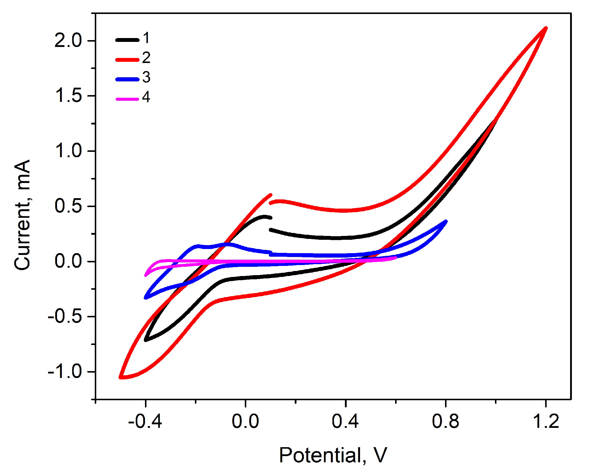
Polymer layers with entrapped MB as a template were electrochemically deposited according to the aforementioned conditions and by applying 3, 5, 7, 10, 15, 20, or 25 potential cycles. The successful polymerisation of pyrrole is visible from the cyclic voltammograms presented in Figure 2 and Figure S1. Furthermore, the increase in the width of the cyclic voltammograms corresponds to an increase in the thickness of the polymer layer. CV is the most widely used technique for acquiring qualitative information about electrochemical reactions. The power of CV is based on the ability to provide rapidly considerable information on the thermodynamics of the redox process, on the kinetics of heterogeneous electron transfer reactions, and on coupled chemical reactions or adsorption processes. In order to find better synthesis conditions to imprint MB into the Ppy layer, we evaluated several different potential ranges vs. Ag/AgCl: from −0.4 V to +1 V (1), from −0.5 V to +1.2 V (2) (as it was described in [24]), from −0.4 V to +0.8 V (3), and from −0.4 V to +0.6 V (4). The comparison of cyclic voltammograms (5th cycle) obtained during the electrochemical polymerisation of polymer layers is presented in Figure 2.
The pyrrole electropolymerisation on glass/ITO starts from +0.5 V [43], so, the electropolymerisation potential ranges in our study were selected between from −0.5 V to +1.2 V. In the ranges from −0.4 V to +0.6 V and from −0.4 V to +0.8 V, the voltammograms lack sufficient anodic peaks to investigate the pyrrole polymerisation. The anodic peak is enhanced, and the pyrrole polymerisation is identified in the cyclic voltammogram in the range from −0.4 V to +1.0 V. Considering the study of Kaplan et al. [26] to indicate the formation of the MB layer on the electrode surface, the current density should steadily decrease at −0.22 V and start increasing at about −0.05 V with the increase in scans. The range from −0.5 V to +1.2 V in our study showed the highest peaks at about −0.05 V towards the MB layer deposition. These results are quite similar to previously reported studies [24,26]. The aim of adjusting the electrochemical polymerisation conditions was to find the potential range in which MB would polymerise as little as possible while retaining Ppy layer growth. In that case, to efficiently deposit the Ppy layer and lower MB electropolymerisation, the potential range for further studies was chosen to be in the smaller potential window from −0.4 V to +1.0 V.
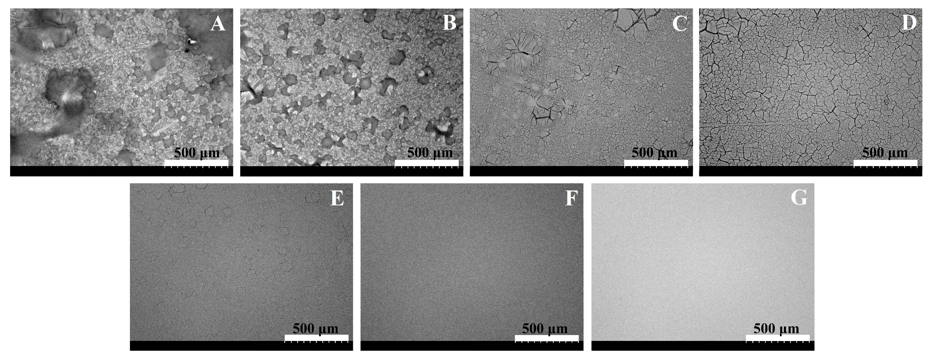
Scanning electron microscopy (SEM) was used to determine the surface morphology of the Ppy-MB layers. The influence of the applied potential cycles (25, 20, 15, 10, 7, 5, or 3) on the Ppy-MB polymer surface properties can be seen in the SEM images at a magnification of ×180 (Figure 3) and magnifications of ×800 and ×8000 (Figure S3). Folded structures and fairly even distributions are observed for the Ppy-MB layers obtained by 25 and 20 potential cycles (Figure 3A,B). Similar results were obtained when studying Ppy-MB layers in previous studies [24]. However, when applying other polymerisation conditions (different potential windows, as shown in Figure 2), it can be observed that layers of the same thickness had denser structures. It was observed that the thicker the layer, the larger and more visible the folds are, and the agglomerations are more noticeable (Figure 3A–C). The thinnest layers seem to be too thin to see clear structures (Figure 3G). A thinner and smoother layer showed better results. A thinner layer is less prone to mechanical damage and lasts longer on the electrode. However, a layer that was obtained by 3 potential cycles is too thin (Figure 3G). Based on the SEM study, it was also assumed that in the further part of this study, it is most functional to use the deposited layers obtained by 5 (Figure 3F), 7 (Figure 3E), and 10 (Figure 3D) potential cycles. (Different magnifications could be found in the supporting material in Figure S3.) Those layers, hereinafter referred to as Ppy-MB-5, Ppy-MB-7, and Ppy-MB-10, were analysed further.
Figure 4 demonstrates the changes in optical absorbance (ΔA) that were measured immediately after deposition in BR buffer solution, pH 3. The potential pulse chronoamperometry was used and set to a total of 5 pulses, as described in the experimental part. Optical absorbance was followed at 530 nm, 668 nm, and 750 nm (conditions were chosen based on previous studies [24]). It is possible to see trends where the change in absorption increases with the layer thickness.
The performance and stability (the ability to both remain mechanically on the electrode surface and the reproducibility of experiments using the same layer) of the electrode modified by the deposited MIP layer imprinted with MB were investigated. The following storage conditions were analysed: BR buffer solution in an acidic medium, water, and air. After a dozen days of conducting tests with such a layer, it was possible to see changes in the cyclic voltammograms (Figure S2). In both cases where voltammograms are obtained in BR buffer solution or water, oxidation peaks were observed at a potential of +0.5 V and reduction peaks at −0.45 V. In the case of storage in air, during cycle 2, the oxidation peak is detected at +0.10 V; however, even two peaks are visible in the reduction region. The peak at −0.15 V can be attributed to the reduction process of the Ppy layer. As the potential changes further up to cycle 10, the oxidation peak shifts to +0.45 V, while the reduction peak remains at −0.15 V. Due to the risk of swelling of the layer in water and BR buffer solution, these storage conditions have been discarded. During the research, it was also noticed that the layer, which was stored in the air, remained attached to the electrode longer. Even with the naked eye, the long-term persistence of the layer on the surface of the electrode was visible when the tests were carried out. The previous study described the Ppy stability on the pencil graphite electrode [44]. The obtained results of our and previous studies prove that storage of the Ppy in the air is more convenient. Afterwards, it was chosen to study the layers that will be stored in the air for further parts of this study.
The further part of this study aimed to analyse the performance of the layer and the influence of the determination and washing procedures on the properties of the polymer layer. The stability of the layers Ppy-MB-5, Ppy-MB-7, and Ppy-MB-10 was checked by washing them in water. After each wash (3 min), the change in optical absorbance (ΔA) was observed. The potential pulse chronoamperometry was applied with 5 pulses, as described in the Experimental section. Simultaneously, the optical absorbance was monitored. A consistently decreasing trend is visible in Figure 5A. It was observed that the Ppy-MB-5 layer lost mechanical stability on the electrode after the third wash (or a similar number of washes), and absorption could not be recorded. Other layers were durable even after 10 washes. The Ppy-MB-7 and Ppy-MB-10 layers displayed the highest stability in this respect. Later, every few weeks, the layers were electrochemically tested, and CVs were recorded with and without a redox probe in the BR buffer solution (Figures S4 and S5), wherein clearly expressed oxidation–reduction peaks were visible. The width of the cyclic voltammograms has decreased over storage time.
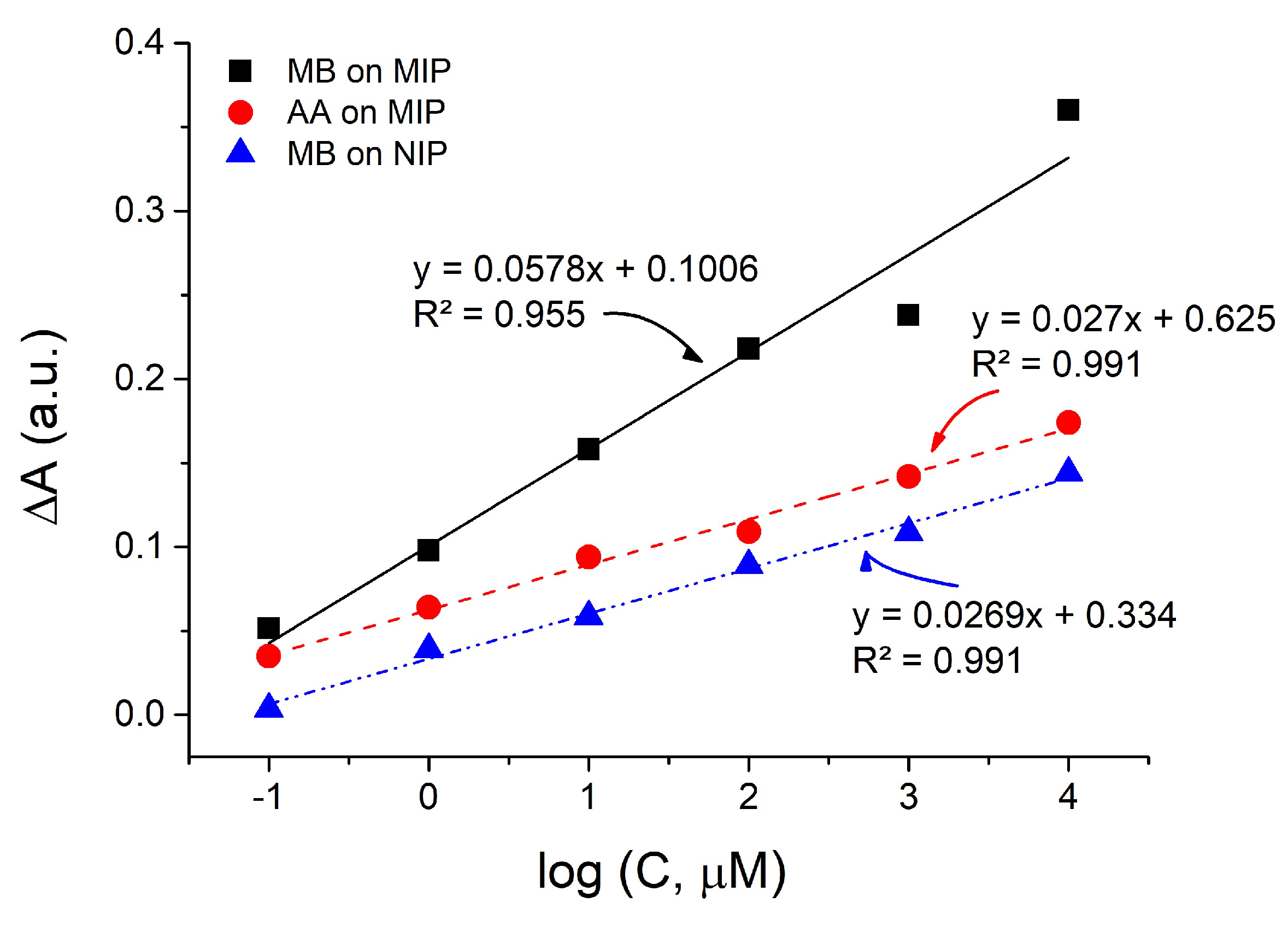
To demonstrate that the resulting polymer is a MIP capable of interacting with MB molecules, the non-specific interaction of another phenothiazine, which in our particular case was Azure A (AA), was examined. A further experiment involved the analysis of the imprinted Ppy as an MB sensor. A non-imprinted polymer (NIP) that did not have MB was also produced to test the effectiveness of the imprinted layer. After evaluating the previous stages of this research, it was found that the most reliable and effective layer can be considered the one that was deposited using 7 potential cycles. It is less thick than Ppy-MB-10, so it stays longer on the surface of the electrode. Also, it is transparent and does not wash off after several detection/washing cycles. For these reasons, further investigation and verification of the sensor as an imprinted Ppy-MB was carried out precisely with this layer. The first task was to remove the imprinted MB from the created layer. For this, 0.1 M sulfuric acid was used, in which the washing lasted for 5 min. The NIP was also washed to create the same experimental conditions. In the following part of the research, the formed MIP and NIP layers were evaluated by observing the change in optical absorption. The concentrations of MB varied from 0.1 μM to 10 mM. The results are presented in Figure 6.
The calibration plots in Figure 6 demonstrate the change in absorption (∆A) on MIP and NIP layers in the presence of MB or Azure A. Linearity was observed at all evaluated calibration graphs in the concentration range from 0.1 μM to 10 mM. It can be seen that R is greater than 0.9: MB on MIP is 0.955, AA on MIP, and MB on NIP is 0.991. The apparent imprinting factor when comparing MB interaction with MIP or NIP is about 2.15. The slope values for the calibration plots of AA on MIP and MB on NIP are roughly the same, while the slope for the calibration plot of MB on MIP is visibly steeper. The magnitude of slope values for calibration plots can be attributed to the strength of target molecule interactions with polymer layers. The slope for MB on MIP being larger than that of MB on NIP was anticipated, as there was no imprinting process during the fabrication of the sensor. Due to the presence of complementary cavities/imprints, MB interacted with MIP both specifically and non-specifically. On the other hand, MB interacted with NIP only non-specifically, thus resulting in smaller slope values. Furthermore, the slope values for MB on MIP and AA on MIP differ similarly, which indicates that MIP is selective for MB molecules. After taking the aforementioned observations into account, it can be concluded that the described procedures can be applied in the development of imprinted Ppy-based sensors for the detection of MB.
Table 1 compares other MB detection ways, but there is no identical one, applying the same methods and materials. A summary of the different detection methods for MB includes information about the sensing platform, evaluation method, and the limit of detection (LOD).
In multiple studies, the detection of MB was successfully achieved using diverse sensing platforms that contained conducting [45] polymer (to form MIP around magnetic Fe3O4 nanoparticles) or non-conducting polymers [46,47] for molecular imprinting. In addition to polymers, different metal-based (silver nanoparticles [48], Fe3O4 nanoparticles [45], and carbon-based (graphene oxide nanosheets, graphitic carbon nitride [48], multi-walled carbon nanotubes [49]) modifications were used to enhance the sensitivity of detection. Each of these articles leveraged the specific evaluation method and modified materials in MB detection, contributing valuable insights into the field of MB sensing.

4. Conclusions

The electrochemical polymerisation of the Ppy layer was carried out by potential cycling. The performance and stability of the MIP-modified electrode were studied. By increasing the number of applied potential cycles during the deposition of the Ppy layers, some morphological differences are visible: the surface of the layer becomes rougher, more folds appear on the surface, and it becomes less transparent. Analyses of Ppy layers were carried out, assessing washability, stability over time, and storage conditions. The most reliable and effective layer can be considered the one that was deposited using seven potential cycles. Later, the analysis of the layers deposited using seven potential cycles as a MIP was conducted. The obtained slope values of the calibration plots display that MIP interacts specifically and is selective for MB in comparison to another phenothiazine derivative, Azure A. This research shows that the MIP with MB imprints can be applied in the development of imprinted Ppy-based sensors sensitive towards MB.

Supplementary Materials

The following supporting information can be downloaded at: https://www.mdpi.com/article/10.3390/chemosensors11110549/s1. Figure S1: Cyclic voltammograms of Ppy-MB during electrochemical deposition. Ppy-MB layers deposited by (AG) 3, 5, 7, 10, 15, 20, 25 potential cycles, respectively; Figure S2: Electrode storage in different mediums (layer polymerized with 25 cycles), after 12 days, (A) 0,01 M BR buffer solution, pH 3; (B) in water; (C) in air; Figure S3: SEM images of Ppy-MB which were electropolymerized by: 25 potential cycles at magnification ×800 (A) and ×8000 (B), 20 potential cycles at magnification ×800 (C) and ×8000 (D), 15 potential cycles at magnification ×800 (E) and ×8000 (F), 10 potential cycles at magnification ×800 (G) and ×8000 (H), 7 potential cycles at magnification ×800 (I) and ×8000 (J), and 5 potential cycles at magnification ×800 (K) and ×8000 (L); Figure S4: Cyclic voltammograms of differently modified electrodes were recorded immediately after deposition in the BR buffer solution without (1) and with (2) K3[Fe(CN)6]/K4[Fe(CN)6] as a redox probe. (A) Ppy-MB-5, (B) Ppy-MB-7, (C) Ppy-MB-10 electrode; Figure S5: Cyclic voltammograms of differently modified electrodes were recorded six weeks after deposition in the BR buffer solution without (1) and with (2) K3[Fe(CN)6]/K4[Fe(CN)6] as a redox probe. (A) Ppy-MB-5, (B) Ppy-MB-7, (C) Ppy-MB-10 electrode.

Author Contributions

R.B.: Methodology, Investigation, Writing—Original Draft, Writing—Review and Editing, and Visualization. G.P.: Investigation, Writing—Original Draft, Writing—Review and Editing, and Visualization. V.R.: Supervision, Conceptualization, Methodology, Validation, Writing—Original Draft, and Writing—Review and Editing. E.B.: Investigation and Writing—Review and Editing. A.R. (Almira Ramanaviciene): Conceptualization and Writing—Review and Editing. A.R. (Arunas Ramanavicius): Resources, Writing—Original Draft, Writing—Review and Editing, Supervision, Project administration, and Funding acquisition. The manuscript was written with the contributions of all authors. All authors have read and agreed to the published version of the manuscript.

Funding

This research was conducted under the Lithuania–Latvian–China (Taiwan) project and it has received funding according to agreement No S-LLT-21-3 from the Research Council of Lithuania (LMTLT) (No. 110-2923-E-002-004-MY3 for Taiwan).

Institutional Review Board Statement

Not applicable.

Informed Consent Statement

Not applicable.

Data Availability Statement

The datasets generated during and/or analysed during the current study are available from the corresponding author upon reasonable request.

Acknowledgments

The authors are grateful to Eugenijus Norkus (Department of Catalysis, State Research Institute Center for Physical Sciences and Technology) for the use of a Scanning Electron Microscope. The authors thank Daniel Garifulin who assisted with some of the initial experiments.

Conflicts of Interest

The authors declare no conflict of interest.

References

  1. Tretjakov, A.; Syritski, V.; Reut, J.; Boroznjak, R.; Öpik, A. Analytica Chimica Acta Molecularly Imprinted Polymer Film Interfaced with Surface Acoustic Wave Technology as a Sensing Platform for Label-Free Protein Detection. Anal. Chim. Acta 2016, 902, 182–188. [Google Scholar] [CrossRef]
  2. Kidakova, A.; Boroznjak, R.; Reut, J.; Öpik, A.; Saarma, M.; Syritski, V. Molecularly Imprinted Polymer-Based SAW Sensor for Label-Free Detection of Cerebral Dopamine Neurotrophic Factor Protein. Sens. Actuators B Chem. 2020, 308, 127708. [Google Scholar] [CrossRef]
  3. Lowdon, J.W.; Diliën, H.; Singla, P.; Peeters, M.; Cleij, T.J.; van Grinsven, B.; Eersels, K. MIPs for Commercial Application in Low-Cost Sensors and Assays—An Overview of the Current Status Quo. Sens. Actuators B Chem. 2020, 325, 128973. [Google Scholar] [CrossRef]
  4. Ratautaite, V.; Janssens, S.D.; Haenen, K.; Nesládek, M.; Ramanaviciene, A.; Baleviciute, I.; Ramanavicius, A. Molecularly Imprinted Polypyrrole Based Impedimetric Sensor for Theophylline Determination. Electrochim. Acta 2014, 130, 361–367. [Google Scholar] [CrossRef]
  5. Mazouz, Z.; Mokni, M.; Fourati, N.; Zerrouki, C.; Barbault, F.; Seydou, M.; Kalfat, R.; Yaakoubi, N.; Omezzine, A.; Bouslema, A.; et al. Biosensors and Bioelectronics Computational Approach and Electrochemical Measurements for Protein Detection with MIP-Based Sensor. Biosens. Bioelectron. 2020, 151, 111978. [Google Scholar] [CrossRef]
  6. Ansari, S.; Masoum, S. Molecularly Imprinted Polymers for Capturing and Sensing Proteins: Current Progress and Future Implications. TrAC—Trends Anal. Chem. 2019, 114, 29–47. [Google Scholar] [CrossRef]
  7. El-Sharif, H.F.; Stevenson, D.; Reddy, S.M. MIP-Based Protein Profiling: A Method for Interspecies Discrimination. Sens. Actuators B Chem. 2017, 241, 33–39. [Google Scholar] [CrossRef]
  8. Dabrowski, M.; Lach, P.; Cieplak, M.; Kutner, W. Nanostructured Molecularly Imprinted Polymers for Protein Chemosensing. Biosens. Bioelectron. 2018, 102, 17–26. [Google Scholar] [CrossRef]
  9. Shumyantseva, V.V.; Bulko, T.V.; Sigolaeva, L.V.; Kuzikov, A.V.; Archakov, A.I. Electrosynthesis and Binding Properties of Molecularly Imprinted Poly-o-Phenylenediamine for Selective Recognition and Direct Electrochemical Detection of Myoglobin. Biosens. Bioelectron. 2016, 86, 330–336. [Google Scholar] [CrossRef]
  10. Tlili, A.; Attia, G.; Khaoulani, S.; Mazouz, Z.; Zerrouki, C.; Yaakoubi, N.; Othmane, A.; Fourati, N. Contribution to the Understanding of the Interaction between a Polydopamine Molecular Imprint and a Protein Model: Ionic Strength and pH Effect Investigation. Sensors 2021, 21, 619. [Google Scholar] [CrossRef]
  11. Erdőssy, J.; Horváth, V.; Yarman, A.; Scheller, F.W.; Gyurcsányi, R.E. Electrosynthesized Molecularly Imprinted Polymers for Protein Recognition. TrAC—Trends Anal. Chem. 2016, 79, 179–190. [Google Scholar] [CrossRef]
  12. Piletsky, S.A.; Alcock, S.; Turner, A.P.F. Molecular Imprinting: At the Edge of the Third Millennium. Trends Biotechnol. 2001, 19, 9–12. [Google Scholar] [CrossRef]
  13. Vasapollo, G.; Sole, R.D.; Mergola, L.; Lazzoi, M.R.; Scardino, A.; Scorrano, S.; Mele, G. Molecularly Imprinted Polymers: Present and Future Prospective. Int. J. Mol. Sci. 2011, 12, 5908–5945. [Google Scholar] [CrossRef]
  14. Ding, S.; Lyu, Z.; Li, S.; Ruan, X.; Fei, M.; Zhou, Y.; Niu, X.; Zhu, W.; Du, D.; Lin, Y. Molecularly Imprinted Polypyrrole Nanotubes Based Electrochemical Sensor for Glyphosate Detection. Biosens. Bioelectron. 2021, 191, 113434. [Google Scholar] [CrossRef]
  15. Xing, X.; Liu, S.; Yu, J.; Lian, W.; Huang, J. Electrochemical Sensor Based on Molecularly Imprinted Film at Polypyrrole-Sulfonated Graphene/Hyaluronic Acid-Multiwalled Carbon Nanotubes Modified Electrode for Determination of Tryptamine. Biosens. Bioelectron. 2012, 31, 277–283. [Google Scholar] [CrossRef]
  16. Uzun, L.; Turner, A.P.F. Molecularly-Imprinted Polymer Sensors: Realising Their Potential. Biosens. Bioelectron. 2016, 76, 131–144. [Google Scholar] [CrossRef]
  17. Haupt, K. Molecularly Imprinted Polymers in Analytical Chemistry. Analyst 2001, 126, 747–756. [Google Scholar] [CrossRef]
  18. Ramanavicius, S.; Jagminas, A.; Ramanavicius, A. Advances in Molecularly Imprinted Polymers Based Affinity Sensors (Review). Polymers 2021, 13, 974. [Google Scholar] [CrossRef]
  19. El-Schich, Z.; Zhang, Y.; Feith, M.; Beyer, S.; Sternbæk, L.; Ohlsson, L.; Stollenwerk, M.; Wingren, A.G. Molecularly Imprinted Polymers in Biological Applications. Biotechniques 2020, 69, 407–420. [Google Scholar] [CrossRef]
  20. Turiel, E.; Esteban, A.M. Molecularly Imprinted Polymers; Elsevier Inc.: Amsterdam, The Netherlands, 2019; ISBN 9780128169063. [Google Scholar] [CrossRef]
  21. Kan, X.; Xing, Z.; Zhu, A.; Zhao, Z.; Xu, G.; Li, C.; Zhou, H. Molecularly Imprinted Polymers Based Electrochemical Sensor for Bovine Hemoglobin Recognition. Sens. Actuators B Chem. 2012, 168, 395–401. [Google Scholar] [CrossRef]
  22. Yola, M.L.; Atar, N. Development of Cardiac Troponin-I Biosensor Based on Boron Nitride Quantum Dots Including Molecularly Imprinted Polymer. Biosens. Bioelectron. 2019, 126, 418–424. [Google Scholar] [CrossRef] [PubMed]
  23. Silva, B.V.M.; Rodríguez, B.A.G.; Sales, G.F.; Sotomayor, M.D.P.T.; Dutra, R.F. An Ultrasensitive Human Cardiac Troponin T Graphene Screen-Printed Electrode Based on Electropolymerized-Molecularly Imprinted Conducting Polymer. Biosens. Bioelectron. 2016, 77, 978–985. [Google Scholar] [CrossRef] [PubMed]
  24. Ratautaite, V.; Boguzaite, R.; Mickeviciute, M.B.; Mikoliunaite, L.; Samukaite-bubniene, U.; Ramanavicius, A.; Ramanaviciene, A. Evaluation of Electrochromic Properties of Polypyrrole/Poly(Methylene Blue) Layer Doped by Polysaccharides. Sensors 2022, 22, 232. [Google Scholar] [CrossRef] [PubMed]
  25. Ion, R.M.; Scarlat, F.; Scarlat, F.; Niculescu, V.I.R. Methylene—Blue Modified Polypyrrole Film Electrode for Optoelectronic Applications. J. Optoelectron. Adv. Mater. 2003, 5, 109–115. [Google Scholar]
  26. Kaplan, I.H.; Daǧci, K.; Alanyalioǧlu, M. Nucleation and Growth Mechanism of Electropolymerization of Methylene Blue: The Effect of Preparation Potential on Poly(Methylene Blue) Structure. Electroanalysis 2010, 22, 2694–2701. [Google Scholar] [CrossRef]
  27. Erdem, A.; Kerman, K.; Meric, B.; Akarca, U.S.; Ozsoz, M. Novel Hybridization Indicator Methylene Blue for the Electrochemical Detection of Short DNA Sequences Related to the Hepatitis B Virus. Anal. Chim. Acta 2000, 422, 139–149. [Google Scholar] [CrossRef]
  28. Pfaffen, V.; Ortiz, P.I.; Córdoba de Torresi, S.I.; Torresi, R.M. On the pH Dependence of Electroactivity of Poly(Methylene Blue) Films. Electrochim. Acta 2010, 55, 1766–1771. [Google Scholar] [CrossRef]
  29. Brett, C.M.A.; Inzelt, G.; Kertesz, V. Poly(Methylene Blue) Modified Electrode Sensor for Haemoglobin. Anal. Chim. Acta 1999, 385, 119–123. [Google Scholar] [CrossRef]
  30. Karyakin, A.A.; Strakhova, A.K.; Karyakina, E.E.; Varfolomeyev, S.D.; Yatslmirsky, A.K. The Electrochemical Polymerization of Methylene Blue and Bioelectrochemical Activity of the Resulting Film. Synth. Met. 1993, 60, 289–292. [Google Scholar] [CrossRef]
  31. Clifton, J.; Leikin, J.B. Methylene Blue. Am. J. Ther. 2003, 10, 289–291. [Google Scholar] [CrossRef]
  32. Tonlé, I.K.; Ngameni, E.; Tcheumi, H.L.; Tchiéda, V.; Carteret, C.; Walcarius, A. Sorption of Methylene Blue on an Organoclay Bearing Thiol Groups and Application to Electrochemical Sensing of the Dye. Talanta 2008, 74, 489–497. [Google Scholar] [CrossRef] [PubMed]
  33. Guo, S.; Huang, Y.; Wei, T.; Zhang, W.; Wang, W.; Lin, D.; Zhang, X.; Kumar, A.; Du, Q.; Xing, J. Amphiphilic and Biodegradable Methoxy Polyethylene Glycol-Block-(Polycaprolactone-Graft-Poly(2-(Dimethylamino)Ethyl Methacrylate)) as an Effective Gene Carrier. Biomaterials 2011, 32, 879–889. [Google Scholar] [CrossRef] [PubMed]
  34. Asman, S.; Yusof, N.A.; Abdullah, A.H.; Haron, M.J. Synthesis and Characterization of a Molecularly Imprinted Polymer for Methylene Blue. Asian J. Chem. 2011, 23, 4786–4794. [Google Scholar]
  35. Houas, A.; Lachheb, H.; Ksibi, M.; Elaloui, E.; Guillard, C.; Herrmann, J.M. Photocatalytic Degradation Pathway of Methylene Blue in Water. Appl. Catal. B 2001, 31, 145–157. [Google Scholar] [CrossRef]
  36. Liu, B.; Cang, H.; Cui, L.; Zhang, H. Electrochemical Polymerization of Methylene Blue on Glassy Carbon Electrode. Int. J. Electrochem. Sci. 2017, 12, 9907–9913. [Google Scholar] [CrossRef]
  37. Mokhtari, Z.; Khajehsharifi, H.; Hashemnia, S.; Solati, Z.; Azimpanah, R.; Shahrokhian, S. Evaluation of Molecular Imprinted Polymerized Methylene Blue/Aptamer as a Novel Hybrid Receptor for Cardiac Troponin I (CTnI) Detection at Glassy Carbon Electrodes Modified with New Biosynthesized ZnONPs. Sens. Actuators B Chem. 2020, 320, 128316. [Google Scholar] [CrossRef]
  38. El Fazdoune, M.; Bahend, K.; Ben Jadi, S.; Oubella, M.; García-García, F.J.; Bazzaoui, E.A.; Asserghine, A.; Bazzaoui, M. Different Electrochemical Techniques for the Electrosynthesis of Poly Methylene Blue in Sodium Saccharin Aqueous Medium. J. Solid. State Electrochem. 2023, 27, 667–678. [Google Scholar] [CrossRef]
  39. Sedelnikova, A.; Poletaeva, Y.; Golyshev, V.; Chubarov, A.; Dmitrienko, E. Preparation of Magnetic Molecularly Imprinted Polymer for Methylene Blue Capture. Magnetochemistry 2023, 9, 196. [Google Scholar] [CrossRef]
  40. Sun, W.; Wang, Y.; Zhang, Y.; Ju, X.; Li, G.; Sun, Z. Poly(Methylene Blue) Functionalized Graphene Modified Carbon Ionic Liquid Electrode for the Electrochemical Detection of Dopamine. Anal. Chim. Acta 2012, 751, 59–65. [Google Scholar] [CrossRef]
  41. Barsan, M.M.; Pinto, E.M.; Brett, C.M.A. Methylene Blue and Neutral Red Electropolymerisation on AuQCM and on Modified AuQCM Electrodes: An Electrochemical and Gravimetric Study. Phys. Chem. Chem. Phys. 2011, 13, 5462–5471. [Google Scholar] [CrossRef]
  42. Phonklam, K.; Wannapob, R.; Sriwimol, W.; Thavarungkul, P.; Phairatana, T. A Novel Molecularly Imprinted Polymer PMB/MWCNTs Sensor for Highly-Sensitive Cardiac Troponin T Detection. Sens. Actuators B Chem. 2020, 308, 127630. [Google Scholar] [CrossRef]
  43. Kim, S.; Jang, L.K.; Park, H.S.; Lee, J.Y. Electrochemical Deposition of Conductive and Adhesive Polypyrrole-Dopamine Films. Sci. Rep. 2016, 6, 30475. [Google Scholar] [CrossRef] [PubMed]
  44. Samukaite-Bubniene, U.; Valiūnienė, A.; Bucinskas, V.; Genys, P.; Ratautaite, V.; Ramanaviciene, A.; Aksun, E.; Tereshchenko, A.; Zeybek, B.; Ramanavicius, A. Towards Supercapacitors: Cyclic Voltammetry and Fast Fourier Transform Electrochemical Impedance Spectroscopy Based Evaluation of Polypyrrole Electrochemically Deposited on the Pencil Graphite Electrode. Colloids Surf. A Physicochem. Eng. Asp. 2021, 610, 125750. [Google Scholar] [CrossRef]
  45. Hu, Y.; Xing, H.; Li, G.; Wu, M. Magnetic Imprinted Polymer-Based Quartz Crystal Microbalance Sensor for Sensitive Label-Free Detection of Methylene Blue in Groundwater. Sensors 2020, 20, 5506. [Google Scholar] [CrossRef] [PubMed]
  46. Soysal, M.; Muti, M.; Esen, C.; Gençdaǧ, K.; Aslan, A.; Erdem, A.; Karagözler, A.E. A Novel and Selective Methylene Blue Imprinted Polymer Modified Carbon Paste Electrode. Electroanalysis 2013, 25, 1278–1285. [Google Scholar] [CrossRef]
  47. Wang, N.; Xiao, S.J.; Su, C.W. Preparation of Molecularly Imprinted Polymer for Methylene Blue and Study on Its Molecular Recognition Mechanism. Colloid. Polym. Sci. 2016, 294, 1305–1314. [Google Scholar] [CrossRef]
  48. Santhoshkumar, S.; Murugan, E. Rationally Designed SERS AgNPs/GO/g-CN Nanohybrids to Detect Methylene Blue and Hg2+ Ions in Aqueous Solution. Appl. Surf. Sci. 2021, 553, 149544. [Google Scholar] [CrossRef]
  49. Hayat, M.; Shah, A.; Nisar, J.; Shah, I.; Haleem, A.; Ashiq, M.N. A Novel Electrochemical Sensing Platform for the Sensitive Detection and Degradation Monitoring of Methylene Blue. Catalysts 2022, 12, 306. [Google Scholar] [CrossRef]
  50. Zhao, D.; Liu, X.; Wei, C.; Qu, Y.; Xiao, X.; Cheng, H. One-Step Synthesis of Red-Emitting Carbon Dots: Via a Solvothermal Method and Its Application in the Detection of Methylene Blue. RSC Adv. 2019, 9, 29533–29540. [Google Scholar] [CrossRef]
  51. Sadrolhosseini, A.R.; Ghasemi, E.; Pirkarimi, A.; Hamidi, S.M.; Taheri Ghahrizjani, R. Highly Sensitive Surface Plasmon Resonance Sensor for Detection of Methylene Blue and Methylene Orange Dyes Using NiCo-Layered Double Hydroxide. Opt. Commun. 2023, 529, 129057. [Google Scholar] [CrossRef]
Figure 1. Schematic representation of the study. (A) A scheme of MB-based sensor evaluation steps. (B) Visualisation of an imprinted Ppy layer on an ITO electrode.
Chemosensors 11 00549 g001
Figure 2. Electrochemical deposition of Ppy-MB during potential cycling at different conditions: (1) from −0.4 V to +1 V; (2) from −0.5 V to +1.2 V; (3) from −0.4 V to +0.8 V; (4) from −0.4 V to +0.6 V. Cyclic voltammograms at a scan rate of 50 mV/s, and a step potential of 2.44 mV. Number of potential cycles in total was 10. The 5th cycle is demonstrated for comparison. Electrochemical polymerisation was performed in a three-electrode system, in which glass/ITO was used as WE, Ag/AgCl as RE, and platinum wire as CE.
Chemosensors 11 00549 g002
Figure 3. SEM images of Ppy-MB synthesised at different conditions ((AG), Ppy-MB layers deposited by 25, 20, 15, 10, 7, 5, or 3 potential cycles, respectively). Magnification is ×180.
Chemosensors 11 00549 g003
Figure 4. Changes of absorbance in different layers of Ppy-MB: Ppy-MB-5, Ppy-MB-7, Ppy-MB-10. Absorbance was measured at λ = 668 nm and λ = 750 nm.
Chemosensors 11 00549 g004
Figure 5. The dependence of change in absorption on the number of times the layer was washed in water. (A) Ppy-MB-5, (B) Ppy-MB-7, (C) Ppy-MB-10. Absorbance was measured at λ = 668 nm (black line) and λ = 750 nm (red line). Error bars represent the standard deviation of ∆A from N = 3.
Chemosensors 11 00549 g005
Figure 6. The calibration plots (∆A vs. log[C, μM]) present the change in absorption on Ppy-MB-7 layers as MIP or NIP, in the presence of MB and Azure A adsorption, λ = 668 nm.
Chemosensors 11 00549 g006
Table 1. Different detection methods for MB.
Sensing PlatformEvaluationLODRef.
QCM/Fe3O4NPs/MIP/PpyQCM-D1.4 µg/L[45]
Carbon paste/MIP/PMAADPV36.4 µM[46]
MIP/PAAUV-Vis spectroscopy-[47]
AgNPs/GO/g-CNRaman spectroscopy0.001 nM[48]
GCE/NH2-fMWCNTsSWV0.21 nM[49]
Red-emitting CDsFluorescence spectroscopy10 nM[50]
Au-glass/NiCo-layered double hydroxideSurface plasmon resonance0.005 ppm[51]
ITO-glass/MIP/PpyPotential pulse chronoamperometry, cyclic voltammetry, UV-Vis spectroscopy-This work
QCM—quartz crystal microbalance; Fe3O4-NPs—Iron(ll,lll) oxide nanoparticles; QCM-D—quartz crystal microbalance with dissipation monitoring; PMAA—polymethacrylic acid; DPV—differential pulse voltammetry; PAA—polyacrylic acid; AgNPs/GO/g-CN—silver nanoparticles/graphene oxide nanosheets/graphitic carbon nitride; GCE/NH2-fMWCNTs—glassy carbon electrode/amino-group functionalized multi-walled carbon nanotubes; SWV—square wave voltammetry; CDs—carbon dots; Au/glass—gold-coated thin glass; ITO—indium tin oxide; Ppy—polypyrrole.
Disclaimer/Publisher’s Note: The statements, opinions and data contained in all publications are solely those of the individual author(s) and contributor(s) and not of MDPI and/or the editor(s). MDPI and/or the editor(s) disclaim responsibility for any injury to people or property resulting from any ideas, methods, instructions or products referred to in the content.