
Energy-Saving and Low-Carbon Gear Blank Dimension Design Based on Business Compass

1
School of Computer and Information, Qiannan Normal University for Nationalities, Duyun 558000, China
2
Key Laboratory of Complex Systems and Intelligent Optimization of Guizhou Province, Duyun 558000, China
3
Key Laboratory of Complex Systems and Intelligent Optimization of Qiannan, Duyun 558000, China
4
Management School, China West Normal University, Nanchong 637002, China
5
School of Economics & Management, Shaoyang University, Shaoyang 422099, China
6
College of Mechanical and Electrical Engineering, Xinjiang Agricultural University, Wulumuqi 830052, China
*
Author to whom correspondence should be addressed.
Processes 2022, 10(9), 1859; https://doi.org/10.3390/pr10091859
Submission received: 22 August 2022
/
Revised: 6 September 2022
/
Accepted: 9 September 2022
/
Published: 15 September 2022
(This article belongs to the Special Issue Process Control and Smart Manufacturing for Industry 4.0)
Abstract
:Sustainable blank dimension design is the key to the implementation of green industrial development. However, blank dimension design only considers the blank production factor of the blank dimension design stage, which cannot guarantee the blank production stage and the use stage’s overall goal. In this paper, based on the guiding thinking of a business compass, a low-carbon and low-energy consumption blank dimension optimization design model was proposed. Taking the process parameters of the production and the use of the blank as the variables, the grey wolf optimization algorithm was adopted to solve the problem. Taking the gear blanks dimension as an example, the optimized blank dimension is 98.6, compared with the standard blank dimension of 100, 105, the energy consumption is 95.7% and 93.1%, the carbon emission is 92.6% and 90.2%, and the material consumption is 96.5% and 87.5%, respectively. The sustainable blank dimension design has obvious advantages in terms of low energy consumption and low carbon, and it can save a lot of materials; it can also promote product sustainability.
1. Introduction
Modern industrial civilization has created unprecedented wealth for humankind and greatly liberated human productivity [1]. However, excessive industrialization and overdraft of resources have seriously damaged the natural environment on which human beings depend for survival, leading to the worsening of global climate change and environmental pollution, as well as the increasing consumption of resources. It poses a threat to the survival of human beings and triggers global thinking on resource use [2,3]. Blank dimension is a key element which to a great degree can decide blank production and use processes’ energy consumption and carbon emission. The blank design stage is very important, and more than 80% of the blank process energy consumption can be determined [4,5,6]. The dimension design of the blank is of great significance to the energy saving and green development of the industry.
Many scholars have studied the blank dimension design. Wan et al. used the forge, a forging simulation software, to conduct finite element analysis of rolling of flange rings, and gave the optimal dimension of the ring blank before the workpiece was rolled [7]. Li et al. designed the blank dimension according to the forging process characteristics, the work hardening characteristics of the material, the mechanical properties of the blank, the wall thickness before and after the blank forging, and the relationship between the inner and outer diameters, it is verified by the case of automobile swaging shaft [8]. Xu et al. established an intelligent derivation model of rolling ring blank dimension based on the BP neural network algorithm. The reliability of the intelligent derivation scheme was verified by finite element simulation and physical experiments [9]. Zhang et al. proposed a node mesh mapping method to design a blank and optimize the shape of the blank according to the mapping relationship between the formed part and the target part and the flow trend of the material point. The method was validated through the forming process of square box parts and automotive pillars [10]. Akinnuli et al. formed a global model based on the deep-drawn shell model to predict the optimal blank diameter required for each determined geometry. The model was validated by comparing the results of the four models with those corresponding to the same model [11]. Xiao et al. proposed the concept of step element based on the processing characteristics of complex box blanks and optimized the process route. The method is verified by the processing of emulsion box blank [12]. Gharehchahi et al. used an iterative numerical simulation method to optimize the boundary shape of the blank through continuous iteration [13].
In terms of machining parameter optimization, Li et al. proposed an energy-saving optimization method for NC turning batch machining process parameters considering tool wear. They used a multi-objective simulated annealing algorithm to optimize. The effectiveness of the method was verified compared with empirical schemes [14]. Liu et al. proposed a process parameter optimization decision-making method based on processing process sample prediction and multi-objective genetic optimization algorithm, which was solved by an improved multi-objective genetic algorithm and genetic-backpropagation (GABP) neural network [15]. Tian et al. established a comprehensive optimization model based on tool selection and cutting parameters and took carbon emissions as the optimization objective. The validity of the model was verified by a turbo machining case. [16]. Li et al. proposed a method to comprehensively optimize process planning and cutting parameters to reduce the total energy consumption of machining and balance the machine workload in the workshop; particle swarm optimization was used to solve it [17]. Khan et al. investigated a holistic analysis of surface quality, energy, cost, and carbon emissions and used a Haynes 25 alloy external cylindrical turning process to analyze trade-offs among multiple objectives [18]. Josh et al. conducted a comparative study on the performance of NSGA-II, MOALO, and MODA in micromachining applications [19]. Zhou et al. proposed a cutting parameter optimization method with a carbon emissions objective. They developed NG-NSGA-II to solve the model and used cylindrical turning as an example to verify the method [20]. Xiao et al. proposed a knowledge-driven energy efficient turning optimization method to minimize specific energy consumption and machining time. Compared with the three algorithms of GA, ACA, and PSO, it showed the superiority of this method. [21]. Shin et al. proposed a toolpath-based energy modeling method to optimize energy consumption online and in real-time, which was validated by milling [22].
The above studies have been well verified. However, these studies only consider the optimization of the forming dimension in the blank production stage or the parameter optimization in the blank use stage, respectively. The blank dimension design needs to consider the production and use process as a whole; the optimality of a single stage cannot guarantee the overall optimality. This paper used the business compass as the top-level design model of enterprise sustainable development to guide the blank dimension design and effectively combined design and management. It comprehensively considered the production and use stages of the blank and constructed a five-factor framework of “environment, human, method, material, and machine” for sustainable blank design based on the business compass. And the “method” in the five elements was the focus of research, a blank dimension optimization design model based on energy-saving and low-carbon was established, and the grey wolf algorithm was used to solve it. It was verified with the example of gear blank to enrich the theoretical research on the sustainable design of blank dimension. This method can take into account the energy consumption and carbon emissions of the blank at each stage of its life cycle and help enterprises quickly design the blank dimension that meets the requirements, which is most conducive to the sustainable development of society.
2. Sustainable Blank Dimension Design Method under the Guidance of the Business Compass
2.1. The Guidance of the Business Compass to Business Operations
The business compass is a multidisciplinary and interdisciplinary theoretical framework for the top-level design of enterprise sustainable development. Business compass organically integrates Chinese philosophy and Western management science based on the people-oriented development concept, refer to the five elements “wood, fire, earth, metal and water” in Chinese Taoist philosophy [23], as shown in Figure 1, it proposes five core elements of “trend, path, skill, tool and profit” for the sustainable development of the enterprise, and progressively constructs fifteen sections, including policy, industry, market, mission, vision, value, strategy, tactics, organization, technology, product, service, internal benefit, external benefit, and society, as well as 119 corporate sustainable development management modules, including economic policy, industrial trends, corporate responsibility, strategic goals, corporate ecology, technological innovation, product development, blank procurement, quality management, company achievements, and entrepreneurship, which is a new multidisciplinary cross-theoretical framework for the top-level design of enterprise sustainable development [24]. The business compass guides all aspects of enterprise operation and has important guiding significance for personnel operation management, equipment operation management, financial operation management, product operation management, etc.
2.2. The Blank Dimension Sustainable Design Framework Based on Business Compass
The guidance of the business compass for product design management can guide the adjustment and optimization of process elements. The essence of sustainable design of blank dimension is to make full use of various scientific and technological design methods, economic management, and other aspects of knowledge according to people’s objective needs [25,26], market forecasts, and multi-channel information materials. Through the creative thinking of technical personnel, after repeated deliberation and judgment, the management will make decisions to convert various design models into prototypes, thereby further obtaining blank products with good performance, high economic benefits, creativity, and sustainable environmental protection [27,28,29].
The business compass can provide guidance for the sustainable development of enterprises. In terms of blank dimension sustainable design, the “trend” is the environment in which a company conducts blank design. In recent years, the manufacturing industry has been developing in the direction of low-carbon and green manufacturing, and enterprise production must keep up with the development trend. The “path” is the purpose of the blank design, the goal of the enterprise is to produce a product, and the blank should be designed according to the product characteristics. The “technology” is choosing the appropriate blank dimension, which needs to be judged according to the product and the current technical level. The “tool” is production equipment, and the performance, parameters, and processing links of production equipment must be considered. The “benefit” is the profit of the product. The product benefits that the blank can bring and the problems it can solve. The business compass is a new way of integrating Chinese and Western management ideas to guide the top-level design of an enterprise. Its five elements of “trend, path, skill, tool, and profit” correspond to the five elements of blank dimension development “environment, human, method, material, and machine.” According to the business compass thinking—the concept of sustainable development of blank dimension—the internal connection of circular economy, the framework of sustainable design of blank dimension has been established, as shown in Figure 2.
The framework of sustainable design of blank dimension based on business compass thinking is a theoretical framework of sustainable development of blank dimension that fully reflects the concept of circular economy development according to the strategic goal of sustainable human development. Its basic idea is to make full use of modern scientific and technological means during the entire life cycle of the blank dimension, whether it is the government, society, enterprises, or individuals within a certain period and a certain range. While meeting the performance of the blank products, natural resources and energy should be positively, actively, and efficiently used, with no pollution or less pollution to the ecological environment, friendly to manufacturers and users, and the final discarded products should be able to be recycled. The wastes that cannot be reused should be properly disposed of to achieve the purpose of cherishing precious natural resources and protecting the ecological environment, thereby promoting the development of a circular economy, and realizing sustainable human development.
More than 80% of the energy consumption and carbon emissions of product processing can be determined in the product design stage. Product design has become an important basis for sustainable design and an important prerequisite for realizing a circular economy. Product design has become an urgent question needed to solve the development of the circular economy. To solve this problem, this paper takes the sustainable design of gears as an example and proposes a blank dimension optimization design model based on low carbon and energy saving.
3. Blank Dimension Optimal Design Model Based on Low-Carbon and Low-Energy Consumption
The blank dimension appears at the last moment of rolling and begins to disappear during the use of the blank, which is a procedural element and has a short existence time. The blank dimension is the sum of back cutting depth and the workpiece dimension. The workpiece dimension is generally known, and the back-cutting depth is a variable in the process and is related to the processing process. Once the machining is completed, the back-cutting depth can be calculated. Therefore, the main work of the research is to optimize the model of energy consumption and carbon emission. The energy consumption and carbon emission models are as follows [30,31,32].
3.1. Energy Consumption Calculation Model Based on Blank Production and Processing
The manufacturing process includes the stages of energy manufacturing, auxiliary material manufacturing, raw material manufacturing, and product manufacturing. The whole process goes through steel making, pouring, undercutting, forging, machining, and other processes, with the assistance of energy (primary energy, secondary energy, electrical energy), cutting fluid, lubricating oil, fixtures, etc., to finally form the raw material of the gear blank. The production of blanks must go through processes such as raw material mining and transportation, blast furnace ironmaking, steelmaking, and steel rolling. Among them, the mining and transportation of materials, blast furnace ironmaking, steelmaking, and other processes have little impact on the design of the blank dimension. Therefore, the effect of the rolling process energy consumption on the blank dimension is only considered here. According to the billet production and use process, the energy consumption can be divided into rolling energy consumption during blank rolling and cutting energy consumption when the blank is cut.
The rolling energy consumption can be expressed as:
where t represents the rolling pass, are expressed as the rolling moment, the rolling speed, the rolling time when t pass represents the t pass rolling energy consumption. represents the roll working diameter, are represented the coefficient, and the rolling pass, respectively. Rolling pass is a variable, connected with total elongation coefficient and the average elongation coefficient , the expression is:
where , are the thermal expansion coefficient, billet side length (),and blank diameter (), respectively. and are the red billet section area (), and the finished product and thermal state section area ().
The energy consumption in blank processing is primarily the electricity consumption of the machine tool equipment, which will directly affect the shape, dimension, and precision of the blank. In addition, it also includes the lighting energy consumption when the blank is used and the product transportation energy consumption.
The electricity consumption of the machine tool equipment in the blank processing is:
where is the machine tool total electrical energy consumption (kWh) in the i step in the part process route, is the machine tool basic energy consumption, which is the energy consumption for the machine tool to keep running when the workpiece is loaded, unloaded, positioned, and clamped on the machine tool (kWh), is the machine tool idle energy consumption, it is the spindle running energy consumption when the tool feeds, retracts and adjusts the tool (kWh), is the energy consumed by the tool to cut parts or change the accuracy and surface quality of the parts (kWh);
V is the material removed volume in the process step (), is the specific energy consumption (), and is the process step working time.
The energy consumption of lighting and product transportation is
is the lighting energy consumption and product transportation energy consumption, is the lighting equipment power (kWh/s), is the workpiece average lighting time (s); is the mth transportation equipment power (kWh/s), and is the average transportation time and cutting time of the workpiece of the m-th transportation equipment.
In conclusion, for a part produced by a process route consisting of i steps, the average power consumption of each workpiece can be expressed as,
3.2. Carbon Emission Calculation Model Based on Blank Production and Processing
3.2.1. Carbon Emissions from the Blank Production Process
The production of blank must go through the mining and transportation of raw materials, iron smelting, steelmaking, rolling, and other processes. Among them, only the rolling process has a greater impact on the blank dimension design. Therefore, only the impact of rolling carbon emissions on blank production is considered here. The energy consumed is mainly electricity in the hot rolling process, and due to the requirements of product quality, some billets need to wait for a period of time to reduce the temperature after they are released from the heating furnace; that is, temperature control can be performed before rolling. Therefore, the carbon emissions from billet hot rolling can be divided into two parts: the electricity produced carbon emissions in the rolling mill and the temperature drop caused carbon emissions during the waiting process of the rolling. They can be expressed as follows:
where, is the rolling mill carbon emission generated by using electricity, is the temperature drop carbon emission caused during the rolling waiting process, is the total number of steel blanks rolled in the steel plant, is the energy consumption carbon emission coefficient, is the temperature drop carbon emission coefficient, represents the time when the billet i starts rolling, is the rolling required time of the blank i.
3.2.2. Material Consumption, Energy Consumption, and Waste Generation in Blank Processing
In the process of gear processing, the reaction of raw materials of gear blanks with auxiliary raw materials, electricity, gas, etc., will produce massive carbon emissions. The carbon emission boundary of gear processing can be set as the entire process from the input of gear raw materials to the output of gear products, including the carbon emissions of materials, energy, and wastes consumed in the gear processing. According to production needs, all kinds of materials i(i = 1, 2,…, I) and energy k(k = 1, 2,..., K) enter the gear blank preparation and gear cutting workshop, and after forging, heat treatment, machining, etc., the finished product is obtained, and waste l(l = 1, 2,…, L) is discharged from each workshop.
The materials, energy consumption, and waste generated by the gear passing through workshop m (m = 1, 2,…, M) are expressed as , ), and respectively. In the processing time T, the total amount of materials consumption, energy consumption, and waste discharged in the gear processing process are respectively expressed as,
According to the material, energy consumption, and waste generation in the process of gear machining, the processing carbon emissions in the process of quantification is as follows:
where , , , represent the total carbon emission, carbon emission of material consumption, carbon emission of energy consumption, carbon emission of waste treatment. Carbon emission can represent as the product of energy consumption (converted to standard coal amount) and carbon emission factor (, where is carbon emission (t), is standard coal amount (t)) by the emission factor method.
3.2.3. Material Carbon Emissions Calculation
In gear processing, the indirect carbon emission generated by the consumption of the ith material in the processing workshop m is:
is the standard coal amount of the c-th energy consumed by the production unit material i, and is the energy c carbon emission factor.
The total indirect carbon emission of material i consumed by gear processing is
The total indirect carbon emission of all materials consumed in gear machining is
3.2.4. Energy Carbon Emission Calculation
There are two types of energy consumption carbon emissions: one is the indirect carbon emission generated in the energy preparation process, and the other is the direct carbon emission , which is caused by the fossil energy consumption in the gear processing process, so .
- (1)
- Indirect carbon emissions
In gear processing, the indirectly emitted carbon emissions generated by the kth energy consumption in the processing workshop m are:
is the standard coal amount of the nth energy consumed by producing unit energy k, and is the energy n carbon emission factor.
The gear processing process total indirect carbon emissions from kth energy consumed are:
The gear processing process total indirect carbon emissions from all energy consumed are:
- (2)
- Direct carbon emissions
In gear processing, the direct emissions of carbon caused by the consumption of the kth fossil energy in the processing workshop m are:
is the standard coal coefficient of energy k, and is the carbon emission factor of energy.
The total direct carbon emissions of kth energy consumed in the gear processing process are:
The total direct carbon emission of energy consumed in the gear processing process are:
3.2.5. Waste Disposal Carbon Emissions
The treatment of wastewater and waste gas generated in the gear processing process consumes electricity and fossil energy. The carbon emission of the waste disposal process generated by the waste l discharged from the manufacturing workshop m are:
where is the standard coal amount of the qth energy consumed by the processing unit waste l, and is the energy q carbon emission factor.
The total carbon emissions from waste l in the gear processing process are:
The total carbon emissions of all waste products in gear processing are:
4. Optimization Model Solution Method
There are many types of algorithms for solving multi-objective problems. Different algorithms have different characteristics. After comparison, we selected the gray wolf optimizer as the solving method of the optimization model.
4.1. Grey Wolf Algorithm Description
Grey Wolf Optimizer (GWO) is a swarm intelligence optimization algorithm that evolved from the ecological predation habit of the grey wolf. Construct a simple and effective optimization mechanism by using wolves of different social classes to jointly guide the wolves to locate the target and realize the predation process of finding prey, surrounding prey, tracking prey, and capturing prey. Relative to the particle swarm algorithm, cuckoo algorithm, and other swarm intelligence algorithms, the gray wolf algorithm has a stronger global search ability. This paper redesigns the update operator of the algorithm. It adds crossover and mutation operations to solve the model so that the optimization of energy consumption, carbon emission, and cost can be realized in the iterative optimization process [33,34,35,36].
It strictly replicates the wolves’ internal hierarchy management system. The design of GWO is to build a social hierarchy pyramid of gray wolves, the first to third layers of the social hierarchy pyramid in the wolf pack, namely the best, second best, and third best wolves are denoted as , respectively, and the remaining wolves at the bottom of the pyramid are referred to as [37,38]. In GWO, guide the wolves to complete the entire hunting (optimization) process, and the wolf must obey the three wolves. This population hierarchy ensures that the process of killing prey is efficient. First, all members of the wolf pack look for, chase, and approach the prey together, and encircle the prey from different angles and directions. As the encirclement circle shrinks, the β and γ wolves that are closest to the prey will attack the prey in the wolf pack led by the wolf. When the prey escapes, the δ will be supplemented to ensure that the wolves continue to tackle the prey in each direction, and finally, catch prey smoothly [39].
First, the gray wolf forms a prey encirclement, and the individual’s distance from the prey is computed as follows:
is the position coordinate of the prey, is the gray wolf’s location coordinates, and t is the number of iterations. A and C are synergy coefficient vectors, which are the convergence factor and the swing factor, respectively.
and are random vectors in the [0, 1] interval, as the number of iterations increases, a gradually decreases linearly from 2 to 0.
Since the position of the prey is unknown in the abstract search space, three wolves (α, β, γ) with the best results are saved in each iteration, and other wolves are guided to approach the prey according to their position information. The update method is as follows:
The search process of GWO is mainly composed of two parts: prey positioning and gray wolves’ movement. First, in the solution space, the gray wolf population is produced randomly, starting from the random population of gray wolves, and then (α, β, γ) guides other individuals to complete the prey capture. A is a random number between [−a, a] because as the number of repetitions increases, a reduces linearly. A has a higher value in the early period of evolution and a lower value in the later period.
When |A| > 1, the gray wolves will expand the encirclement and suppression circle to increase the search range so that the wolves can search for prey in a wider range and ensure the global search ability of the algorithm. When |A| < 1, the gray wolves will shrink the encircling circle to attack and capture the prey. Finally, when the stopping condition is satisfied, it will capture the prey and output the optimal solution [40,41,42].
4.2. Algorithm Flow
The flow chart of GWO is shown in Figure 3, including the following steps.
Step 1. Code the process route, equipment, and tool.
Step 2. Population initialization and parameter setting.
Step 3. Sort the solution set.
Step 4. Determine whether the termination condition is reached, output the result if it is reached, and go to Step 5 if it is not reached.
Step 5. Four social classes of wolves were established, the wolves hunt under the leadership of the alpha wolf, and the solution set is obtained by cross-mutation.
Step 6. Merge the new wolf group obtained in Step 5 with the previous old wolf group.
Step 7. Update the population position.
Step 8. Output the optimal solution, and the algorithm ends.
4.3. Encoding and Decoding
In order to solve the problem of process route optimization, the selection of equipment and tools and the sequence of processes need to be reasonably reflected in the part coding method in the algorithm. Each individual in the population has three substrings, including the workpiece process route sequence, equipment, and tools; the number of steps in the component is equal to the extent of the three substrings, as shown in Figure 4. The order substring represents the operation order of part processing in a continuous list, and its genes should take into account the constraints of processing priority. The equipment substring consists of the equipment number that has been assigned to each operation, and the jth gene on the substring represents the equipment used to complete operation j. The meaning of the tool substring is similar to that of the equipment substring.
4.4. Population Initialization and Fitness Function
According to the above coding method, each wolf (solution) is a sequence, and the initial solution is obtained by random initialization. Individuals in the wolf pack are classified according to their fitness level using the fitness function. During the position update process of the gray wolf, the wolves with higher fitness are reserved, and the gray wolves with lower fitness are assigned to search for and capture the prey. According to the cutting parameters of the process, the corresponding fitness value is calculated. In this paper, two objective functions, f1 (energy consumption in the manufacturing process) and f2 (carbon emissions in the manufacturing process), are integrated into one fitness function by the weight method. The weight is set as , the fitness function is as follows,
and are the ith wolf’s fitness values, respectively. and represent the maximum and minimum energy consumption, respectively, when the only optimization goal is to reduce the energy consumption of the manufacturing process. and respectively represent the maximum and minimum carbon emissions obtained when the carbon emission of the manufacturing process is taken as the single optimization objective, represent the weight of the corresponding item, and satisfy +. The analytic hierarchy process, the fuzzy evaluation approach, the expert scoring method, the group decision-making method, and other methods can be used to determine the weight.
4.5. Constraints
The selection of cutting parameters for blank development is affected by many aspects. The rolling process is constrained by the bite angle and the stability conditions of the rolling stock in the pass. The cutting parameters of the process are subject to the constraints of machine tool speed, feed, cutting force, machine tool cutting power and roughness, etc., which can be expressed as follows,
- (1)
- Biting condition.
The actual bite angle of the rolling piece should be less than the maximum bite angle of the rolling mill pass to make the rolling piece enter the roll smoothly,
- (2)
- Stability condition of the rolling piece in the pass.
- (3)
- Machine tool speed constraint.
The cutting speed directly determines the spindle speed, and the spindle speed will directly affect the tool life and the processing effect of the workpiece. After the machine tool is determined, the spindle speed of the machine tool should be within the spindle speed range specified by the allowable nameplate of the machine tool,
where and indicate the machine tool spindle’s minimum and maximum speeds, respectively.
- (4)
- Feed limit constraint.
In order to achieve the machining accuracy criteria, the value of the machine feed or feed speed selected for the process must be within the range of the feed specified by the allowable nameplate,
where and are the feed rates of the minimum and maximum level of the lathe respectively. and are the feed rates of the minimum and maximum level of the milling machine, respectively.
- (5)
- Cutting force constraint.
The dimension of the cutting force will affect the life of the machining resources and machining accuracy. During the cutting process, the overall cutting force, which includes the main cutting force, rear force, and feed force, cannot exceed the maximum cutting force allowed by the machine tool.
where , , and are the main cutting force, rear force, and feed force in the turning process, respectively. Taking turning as an example, , , , , are the relevant coefficients of turning main cutting force, , , , , are the correlation coefficients of turning feed force, , , , , are the correlation coefficients of turning back force. The above coefficients are related to the processing conditions and workpiece material and can be obtained by consulting the cutting allowance manual. At the same time, the feed force of the machine tool must be within the allowable feed force range,
- (6)
- Machine tool power constraint.
During the machining process, the machine tool’s output power is connected to the main cutting force , the cutting speed , and the effective coefficient of the selected machine tool power. The output power of the machine tool must also be controlled within the range of the effective cutting power allowed by the machine tool.
- (7)
- Feature roughness constraint.
Each machining feature of the part has machining quality requirements, the selection of cutting parameters in process i must ensure the surface quality of the machining feature, and the roughness must meet the Equation (50),
where r is the tool nose arc radius, the maximum allowable surface roughness is .
4.6. Establishing Population Classes and Location Updates
Since the search process of the original GWO algorithm is guided by three optimal solutions, but the Pareto solution set is obtained in the multi-objective optimization process, so the population is divided into multiple levels according to the dominance relationship, the non-dominated solutions are denoted by and , respectively. When the number of non-dominated levels of the population is 1, are randomly generated by the population; when the number of non-dominated levels is 2, is derived from the first level, and are derived from the second level; When the number of non-dominant level is 3 and above, , and are obtained from the above three ranks, respectively [43,44].
Since the gray wolf algorithm was originally designed to handle continuous optimization issues, so as to ensure that the solutions generated by each evolution are feasible for the process planning problem, a transformation method is used to improve the update operator to achieve neighborhood changes and select one of them as the offspring with equal probability, as shown below.
where, indicates that the individual can move left or right, and indicates the distance that the element moves , is a random number in [0, 1], and C takes 1 in this paper. The shift function can help the wolves to update their positions.
4.7. Genetic Operations
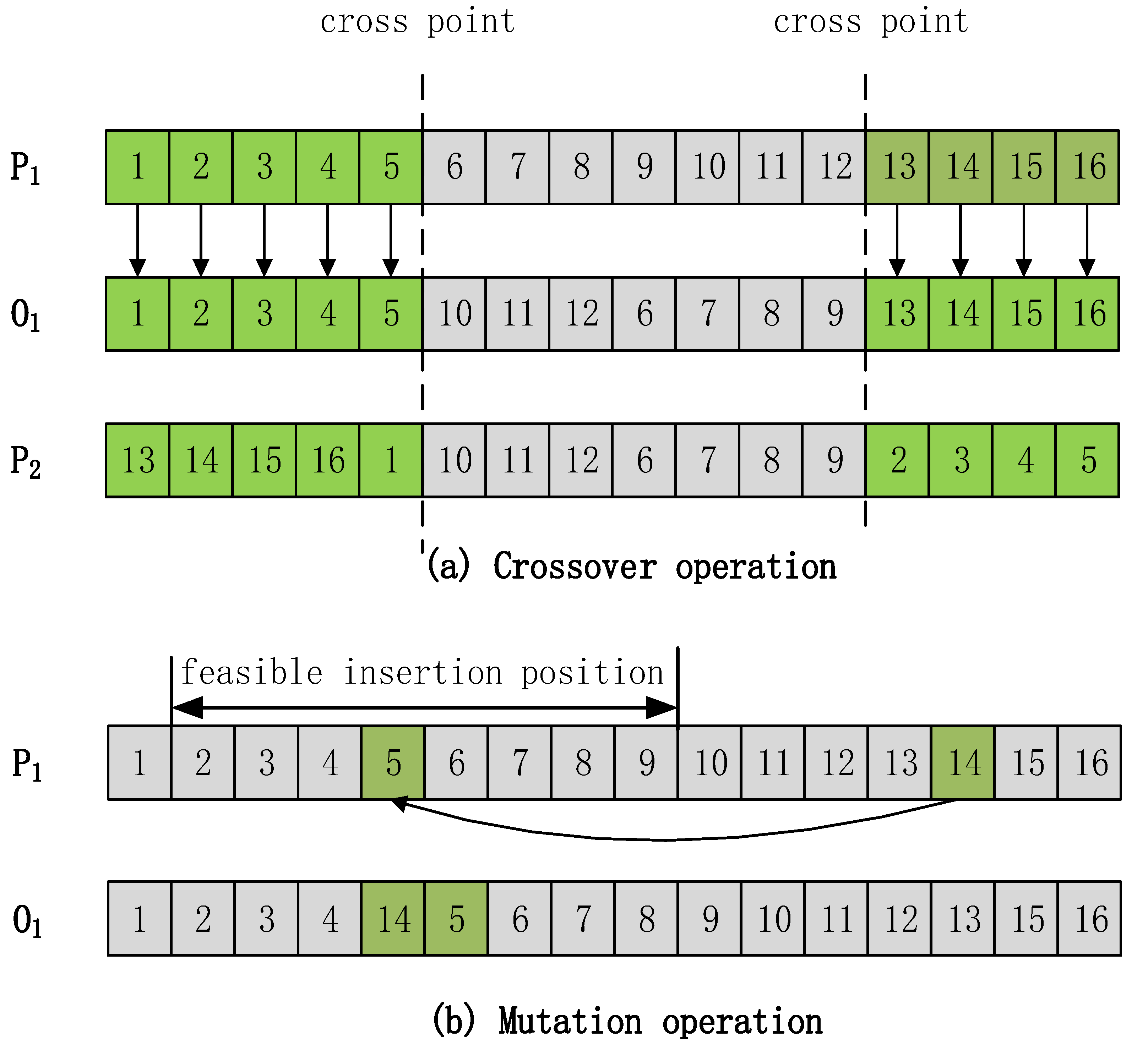
Genetic operations generally fall into two categories: crossover and mutation, the genetic operations are different for each substring. For the sake of algorithm efficiency, the two-point intersection is adopted for the equipment substring and the tool substring. The mutation operation of equipment substrings and tool substrings is performed by selecting points to replace any optional equipment, tools, and machining paths, as shown in Figure 5a. Use an improved two-point intersection method for sequential substrings. The operator will inherit the effective sequence substrings that satisfy the priority constraints and avoid duplication and omission. Two splicing points are randomly selected in the substring. The genes before splicing site 1 and after splicing site 2 in parent P1 are directly copied to the same site in offspring O1, remove the existing genes of O1 in the parental P2, and copy the remaining genes to the remaining sites of O1 (and the gene segment between the two splicing sites) according to the order in P2. For another offspring, O2, it is generated according to the same principle after swapping P1 and P2. This intersection operation can result in an order of operations that does not violate constraints [45,46,47].
The mutation operation of sequential substrings is as follows: first, a process is randomly selected, and then a potential site is defined on the substring, that is, the site where the selected process can be replaced without violating the priority constraint. In the flexible sequence problem, the selected operation needs to satisfy all its predecessors and takes precedence over all its immediate successors. Therefore, potential sites appear consecutively on the substring. Among the potential insertion sites, one was randomly selected to replace the site that was initially selected, as shown in Figure 5b.
5. Case Study
5.1. Instance Parameters
A factory received the task of designing the blank of the second gear of the automobile transmission intermediate shaft (20CrMnTiH, the outer diameter is 97.25 mm, the tooth thickness is 15 mm, the modulus is 1.75 mm, the number of teeth is 46, and the weight is about 0.665 kg), the quantity is 500,000 pieces. The manufacturing process must meet the requirements of circular economy development.
The business compass is a model that guides enterprises to design for sustainable development. It can be used for research ranging from enterprise business strategy path selection to small research on product design. Specific to the design of the automobile transmission gear blank, we analyzed the existing situation and production needs of the enterprise. Based on the theoretical framework of the business compass, we can dynamically guide the optimization selection of the objective influencing factors in the design process from the requirements of the blank design. The machining parameters at the time of the obtained target optimal value are reversed to calculate the blank dimension.
5.2. Experimental Equipment and Parameters
The existing rough rolling equipment of the enterprise is: the entire rolling line uses a total of 22 rolling mills, which are divided into roughing, neutralizing, first finishing, and second finishing mills, arranged in the way of 4, 6, 6, and 6, respectively. The billet used is 45 steel, and the length and width are both 165 mm. The process flow of continuous round steel rolling is shown in Figure 6. The heated billet is sent to the rough rolling mills for four passes, cut head by the #1 flying shear, sent to the medium rolling mills for six passes, cut head by the #2 flying shear, and sent to the first finishing rolling mills for six passes, cut head by the #3 flying shear, sent to the second finishing rolling mills for six passes, the ruler is cut by the flying shears, and then sent to the cooling bed for cooling. Finally, it is automatically collected and bundled, and the finished products are collected and put into the warehouse. The company’s existing blank processing conditions are: there are two CNC lathes (M1, M2), two CNC milling machines (M3, M4), one drilling machine (M5), and one grinding machine (M6) in the workshop, involving turning and milling, drilling, grinding four processing methods. According to the actual processing conditions, the detailed information of the machine tool is shown in Table 1, Table 2 is the turning tool parameters, and Table 3 is the turning force coefficient.
The carbon emission factors of the material preparation process produced by gear processing are shown in Table 4; Table 5 shows the values of indirect carbon emission factors of energy consumption in the process of energy preparation; Table 6 shows the relevant factor values of direct carbon emissions from the consumption of fossil energy; Table 7 shows the relevant factor values of carbon emissions from waste disposal.
According to the energy consumption and carbon emission calculation model proposed above, some required equipment parameter information has been listed, and the GWO was used to optimize and solve the model. The parameters of the algorithm are as follows: population number is 100, maximum generation number is 500, crossover rate is 0.8, the mutation rate is 0.1, and the optimization goal is a low carbon and low energy consumption.
5.3. Optimization Results and Analysis
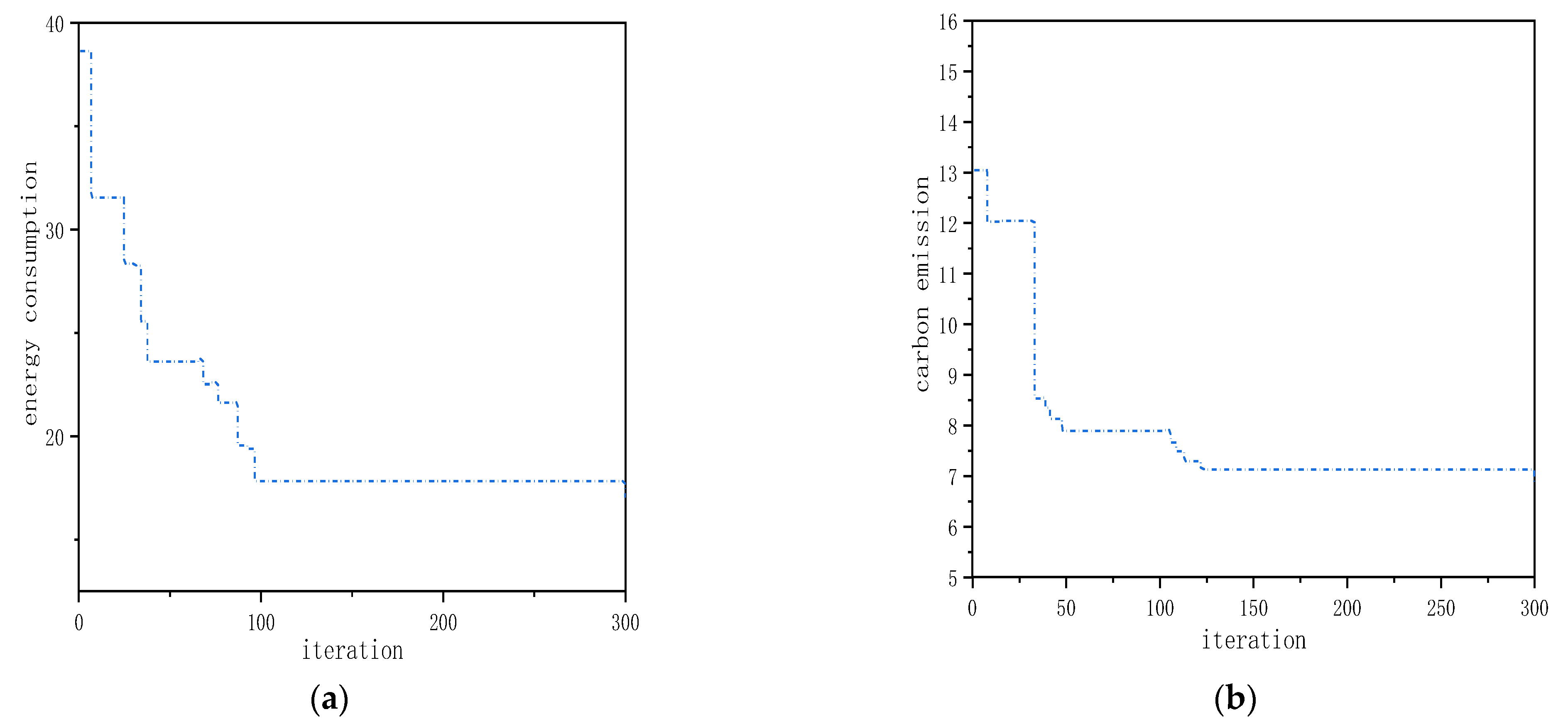
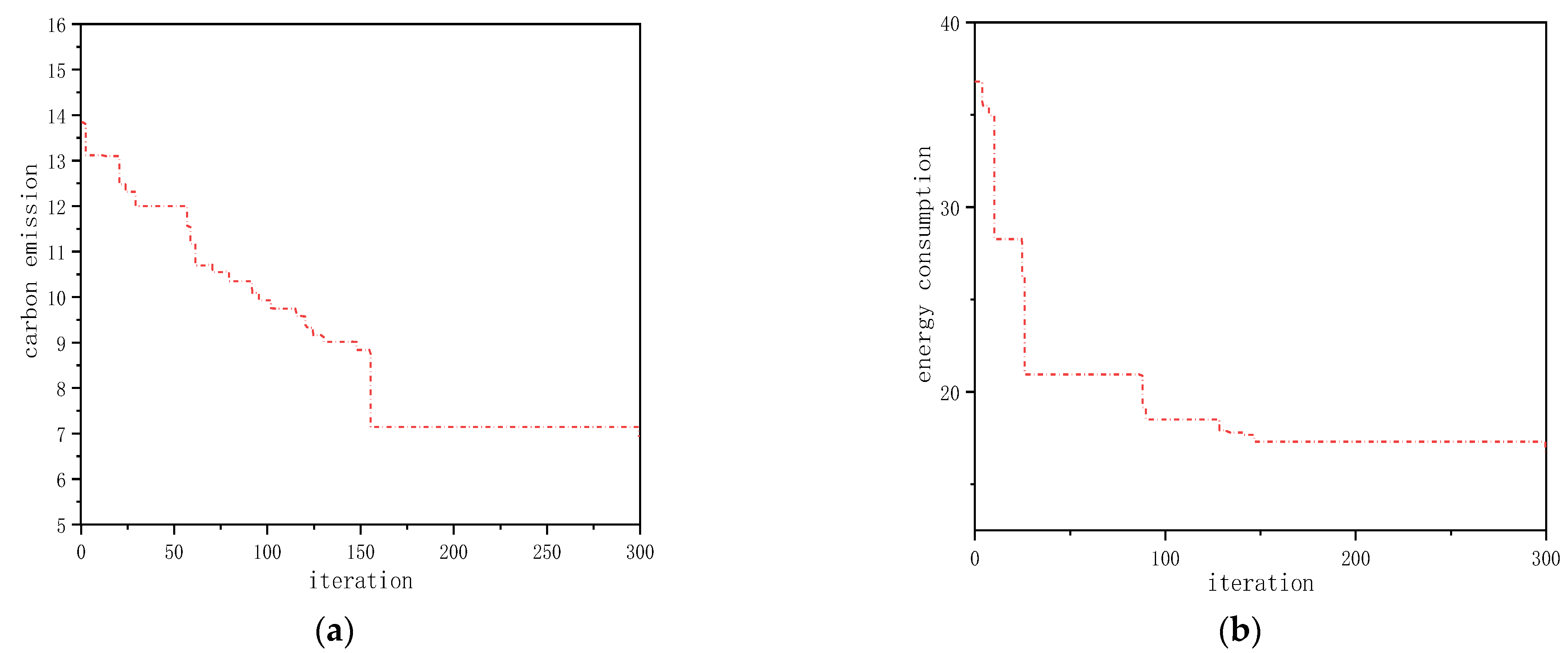
The optimized blank dimension is 98.6, compared with the optimized blank dimension of the standard dimension of 100 and 105, respectively, the algorithm convergence diagrams of carbon emission and energy consumption are shown in Figure 7, Figure 8 and Figure 9.
The coordinated optimization of many elements in the production and use of blanks can result in optimal energy consumption and carbon emission. The blank dimension designed according to sustainable thinking is 98.6, the energy consumption per piece is 15.865, the carbon emission is 6.31, and the material consumption is 0.893. The standard blank dimensions of 100 and 105 are selected for comparison. As shown in Table 8, the optimal energy consumption is 16.57 and 17.03, carbon emissions are 6.93 and 6.85, and material consumption is 0.925 and 1.02. Compared with the available selected blank dimensions of 100 and 105, and considering enterprise conditions, the optimal designed blank dimension’s energy consumption is only close to 95.7% and 93.1% of the selected blank dimensions, respectively, and the carbon emission is 92.6% and 90.2% of the selected dimensions, respectively. Material consumption is close to 96.5% and 87.5% of the selected dimensions, respectively. This batch of gears requires 500,000 pieces. Compared with the standard dimension 100 and 105 blanks, the optimized blanks reduce energy consumption by 3.525 × 10⁵ and 5.825 × 10⁵ and reduce carbon emissions by 3.1 × 10⁵ and 2.7 × 10⁵, decreasing material consumption by 1.6 × 10⁴ and 6.3 × 10⁴, respectively. The above results showed that the optimized blank dimension could not only save a lot of energy consumption and reduce carbon emissions but also save a lot of production materials. It can be seen that the blank dimension design method has the advantages of saving energy and low carbon and reducing resource consumption. This method can help enterprises design the blank dimension according to the requirements of enterprise energy saving and low carbon and provide suggestions for the sustainable development of enterprises.
5.4. Comparison with Previous Works
In the first chapter, the literature [7,8,9,10,11,12,13,14,15,16,17,18,19,20,21,22] provides many ideas and methods of blank dimension optimization, which effectively achieves the goal. However, the literature [7,8,9,10,11,12,13] only considered the blank production stage and optimized the blank shape and forming process. The literature [14,15,16,17,18,19,20,21,22] only considered the blank use stage and optimized the design of the processing parameters in the use process. The production and use of blanks are a unified whole, and sustainable design blanks need to be considered together. Based on the business compass, this paper comprehensively considered the production and use stages of blanks and constructed a calculation model for energy consumption and carbon emissions during blank production and use was proposed. The improved gray wolf algorithm was used to solve the problem, which was faster.
Compared with references 14–22, the selection of energy consumption and carbon emission as research objects is more in line with the requirements of the times and compared with the optimization methods in references 14–22, compared with the blank selection in references 14–22, the designed blank dimension can save energy consumption and carbon emission by more than 4%.
5.5. Practical Implications and Future Steps
In this paper, a blank dimension design method considering process variation was proposed and verified by a machining case of gear blank. This research can provide guidance for enterprises to design energy-saving and low-carbon blank dimensions and help the manufacturing industry improve the utilization rate of raw materials and energy. Implementing blank dimension optimization design will help governments and business managers develop energy-saving and low-carbon strategies to reduce the harmful environmental impact of their products. However, this paper only considered the impact of blank dimension design on energy-saving and low-carbon objectives, and future research should include consideration of the impact on more objectives, as well as the impact of blank dimension optimization design on other types of process equipment and process elements.
6. Conclusions
- In order to achieve the goal of minimum energy consumption and carbon emission in the process of blank production and use, the optimization design of the blank dimension is carried out. The factors in the process of blank production and use are coordinated according to the business compass, and an energy-saving and low-carbon blank dimension optimization design method considering the process of dynamic change is proposed. The gray wolf algorithm is used to solve the calculation model. Taking gear blank as an example, the feasibility of the method is verified. Compared with the two standard blank dimensions, 100 and 105, this method can reduce energy consumption by 4.3% and 6.9%, respectively, and reduce carbon emissions by 7.4% and 9.8%, respectively. The results show that this method can effectively help production managers and designers design appropriate blank dimensions to achieve the goal of energy saving and emission reduction in the process of blank production and use.
- The value of this method mainly lies in: (1) selecting the optimization design of blank dimension, which is less studied at present, to analyze the process of energy consumption and carbon emission change in the process of blank production and processing; (2) taking the business compass as a guide, comprehensively coordinating the factors of the stage of blank production and the stage of using; (3) selecting the optimization objective which synthetically considers the energy-saving and low-carbon composite economic indexes, and establishing the optimization model of processing parameters.
Author Contributions
Conceptualization, Y.X. and R.W.; methodology, Y.X., J.Z. and R.W.; software, Y.X.; validation, J.Z. and R.W.; formal analysis, J.Z. and R.W.; investigation, Y.X. and X.Z.; writingtable—original draft preparation, Y.X. and H.Z.; writing—review and editing, Y.X. and H.Z.; visualization, X.Z. All authors have read and agreed to the published version of the manuscript.
Funding
The authors are grateful for National Science Foundation, China (No.s 61862051, 51975432); Natural Science Foundation of Hunan Province, China (No. 2022JJ50244); China Education Department of Hunan Province (No. 21B0695); Project of Hunan social science achievement evaluation committee in 2022 (No. XSP22YBC081); the Science and Technology Foundation of Guizhou Province under Grant (No. [2019]1299); the Top-notch Talent Program of Guizhou province under Grant (No. KY [2018]080); the Program of Qiannan Normal University for Nationalities under Grant (Nos. QNSY2018JS013, QNSYRC201715).
Institutional Review Board Statement
Not applicable.
Informed Consent Statement
Informed consent was obtained from all subjects involved in the study.
Data Availability Statement
Not applicable.
Conflicts of Interest
The authors declare no conflict of interest.
References
- Hirschnitz-Garbers, M.; Tan, A.R.; Gradmann, A. Key drivers for unsustainable resource use–categories, effects and policy pointers. J. Clean. Prod. 2016, 132, 13–31. [Google Scholar] [CrossRef]
- Murray, A.; Skene, K.; Haynes, K. The circular economy: An interdisciplinary exploration of the concept and application in a global context. J. Bus. Ethics 2017, 140, 369–380. [Google Scholar] [CrossRef]
- Lin, K.; Zhao, H. The Impact of Green Finance on the Ecologicalization of Urban Industrial Structure-Based on GMM of Dynamic Panel System. J. Artif. Intell. Technol. 2022, 2, 123–129. [Google Scholar] [CrossRef]
- Zheng, J.; Feng, G.; Ren, Z. China’s energy consumption and economic activity at the regional level. Energy 2022, 259, 124948. [Google Scholar] [CrossRef]
- Zhou, L.; Li, J.; Li, F. Energy consumption model and energy efficiency of machine tools: A comprehensive literature review. J. Clean. Prod. 2016, 112, 3721–3734. [Google Scholar] [CrossRef]
- Starman, B.; Cafuta, G.; Mole, N. A Method for Simultaneous Optimization of Blank Shape and Forming Tool Geometry in Sheet Metal Forming Simulations. Metals 2021, 11, 544. [Google Scholar] [CrossRef]
- Wan, M.Z.; Zhu, Q.H.; Wu, J. Research and Development of Forming Process for Super Heavy Flange Forgings with Thick Wall. Hot Work. Technol. 2020, 49, 123–125. [Google Scholar]
- Li, D.C.; Lu, X.; Sun, Z.Y. Investigation on workblank size requirements of rotary-swaging shafts of an automobile. J. Plast. Eng. 2019, 26, 72–76. [Google Scholar]
- Xu, L.L.; Deng, J.D.; Hu, Z.L.; Xu, L. Intelligent deduction design method of ring forging rolling blank based on machine learning. J. Plast. Eng. 2022, 29, 23–29. [Google Scholar]
- Zhang, X.Q.; Wang, Y.; Wang, C.; Hu, P. Blank Optimization for Sheet Metal Forming Using Inverse Finite Element Method and Mesh Mapping. J. Shanghai Jiaotong Univ. 2019, 53, 1389–1394. [Google Scholar]
- Akinnuli, B.O.; Olatunji, O.E.; Bodunde, O.P. Symmetrical shell deep drawing material optimal blank diameter prediction and waste control model. Arctic 2018, 71, 60–69. [Google Scholar]
- Xiao, Y.; Yan, W.; Wang, R. Research on Blank Optimization Design Based on Low-Carbon and Low-Cost Blank Process Route Optimization Mode. Sustainability 2021, 13, 1929. [Google Scholar] [CrossRef]
- Gharehchahi, H.; Kazemzadeh-Parsi, M.J.; Afsari, A. Optimum blank shape design in deep drawing process using a new boundary updating formula. Int. J. Mater. Form. 2021, 14, 1375–1389. [Google Scholar] [CrossRef]
- Li, C.B.; Yu, B.S.; Xiao, Q. A Cutting Parameter Energy-saving Optimization Method for CNC Turning Batch Processing Considering Tool Wear. J. Mech. Eng. 2021, 57, 217–229. [Google Scholar]
- Liu, Y.; Yan, C.; Ni, Y.; Mou, Y. Multi-objective Optimization Decision of High-speed Dry Hobbing Process Parameters Based on GABP and Improved NSGA-II. China Mech. Eng. 2021, 32, 1043–1050. [Google Scholar]
- Tian, C.; Zhou, G.; Zhang, J.; Wang, C. Integration optimization of tool selection and cutting parameters based on machining features considering carbon emissions. Comput. Integr. Manuf. Syst. 2020, 26, 2060–2072. [Google Scholar]
- Li, L.; Li, C.; Tang, Y. An integrated approach of process planning and cutting parameter optimization for Energy-aware CNC Machining. J. Clean. Prod. 2017, 162, 458–473. [Google Scholar] [CrossRef]
- Khan, A.M.; Liang, L.; Mia, M. Development of process performance simulator (PPS) and parametric optimization for sustainable machining considering carbon emission, cost and energy aspects. Renew. Sustain. Energy Rev. 2021, 139, 110738. [Google Scholar] [CrossRef]
- Joshi, M.; Ghadai, R.K.; Madhu, S. Comparison of NSGA-II, MOALO and MODA for Multi-Objective Optimization of Micro-Machining Processes. Materials 2021, 14, 5109. [Google Scholar] [CrossRef]
- Zhou, G.; Qi, L.; Xiao, Z. Cutting parameter optimization for machining operations considering carbon emissions. J. Clean. Prod. 2018, 208, 937–950. [Google Scholar] [CrossRef]
- Xiao, Q.; Li, C.; Tang, Y. A knowledge-driven method of adaptively optimizing process parameters for energy efficient turning. Energy 2019, 166, 142–156. [Google Scholar] [CrossRef]
- Shin, S.; Woo, J.; Rachuri, S. Energy efficiency of milling machining: Component modeling and online optimization of cutting parameters. J. Clean. Prod. 2017, 161, 12–29. [Google Scholar] [CrossRef]
- Wang, R.P. Business Compass; Science Press China: Beijing, China, 2020. [Google Scholar]
- Xiao, Y.; Wang, R.; Yan, W.; Ma, L. Optimum Design of Blank Dimensions Guided by a Business Compass in the Machining Process. Processes 2021, 9, 1286. [Google Scholar] [CrossRef]
- Khan, M.; Idrees, M.; Rauf, M. Green Supply Chain Management Practices’ Impact on Operational Performance with the Mediation of Technological Innovation. Sustainability 2022, 14, 3362. [Google Scholar] [CrossRef]
- Bocken, N.M.; Pauw, I.; Bakker, C.; Grinten, B.C. Product design and business model strategies for a circular economy. J. Ind. Prod. Eng. 2016, 33, 308–320. [Google Scholar] [CrossRef]
- Maxwell, D.; Vorst, R. Developing sustainable products and services. J. Clean. Prod. 2003, 11, 883–895. [Google Scholar] [CrossRef]
- Vrchota, J.; Pech, M.; Rolínek, L. Sustainability Outcomes of Green Processes in Relation to Industry 4.0 in Manufacturing: Systematic Review. Sustainability 2020, 12, 5968. [Google Scholar] [CrossRef]
- Xu, B.; Qu, H. Impact of the design industry on carbon emissions in the manufacturing industry in china: A case study of zhejiang province. Sustainability 2022, 14, 4261. [Google Scholar] [CrossRef]
- Hammond, G.P.; Jones, C.I. Embodied Energy and Carbon In Construction Materials. Constr. Mater. 2009, 162, 1–64. [Google Scholar] [CrossRef]
- Li, R.; Liu, Q. Service-oriented Research on Multi-pass Milling Parameters Optimization for Green and High Efficiency. Chin. J. Mech. Eng. 2015, 51, 89–98. [Google Scholar] [CrossRef]
- Xiao, Y.; Zhang, H.; Jiang, Z. An approach for blank dimension design considering energy consumption. Int. J. Adv. Manuf. Technol. 2016, 87, 1229–1235. [Google Scholar] [CrossRef]
- Lu, C.; Gao, L.; Li, X. A hybrid multi-objective grey wolf optimizer for dynamic scheduling in a real-world welding industry. Eng. Appl. Artif. Intell. 2017, 57, 61–79. [Google Scholar] [CrossRef]
- Komaki, G.M.; Kayvanfar, V. Grey Wolf Optimizer algorithm for the two-stage assembly flow shop scheduling problem with release time. J. Comput. Sci. 2015, 8, 109–120. [Google Scholar] [CrossRef]
- Teng, Z.J.; Lv, J.L.; Guo, L.W. An improved hybrid grey wolf optimization algorithm. Soft Comput. 2019, 23, 6617–6631. [Google Scholar] [CrossRef]
- Xiao, Y.M.; Zhang, H. Multiobjective optimization of machining center process route: Tradeoffs between energy and cost. J. Clean. Prod. 2021, 28, 21–26. [Google Scholar] [CrossRef]
- Joshi, H.; Arora, S. Enhanced Grey Wolf Optimization Algorithm for Global Optimization. Fundam. Inform. 2017, 153, 235–264. [Google Scholar] [CrossRef]
- Zhou, B.; Lei, Y. Bi-objective grey wolf optimization algorithm combined Levy flight mechanism for the FMC green scheduling problem. Appl. Soft Comput. 2021, 111, 107717. [Google Scholar] [CrossRef]
- Dong, Y.; Liu, J.; Liu, Y. The Optimization Research of Diesel Cylinder Gasket Parameters Based on Hybrid Neutral Network and Improved Grey Wolf Algorithm. Math. Probl. Eng. 2020, 2020, 1–16. [Google Scholar] [CrossRef]
- Huang, G.; Cai, Y.; Liu, J. A Novel Hybrid Discrete Grey Wolf Optimizer Algorithm for Multi-UAV Path Planning. J. Intell. Robot. Syst. 2021, 103, 1–18. [Google Scholar] [CrossRef]
- Karakoyun, M.; Ozkis, A.; Kodaz, H. A new algorithm based on grey wolf optimizer and shuffled frog leaping algorithm to solve the multi-objective optimization problems. Appl. Soft Comput. 2020, 96, 106560. [Google Scholar] [CrossRef]
- Choubey, C.; Ohri, J. Optimal Trajectory Generation for a 6-DOF Parallel Manipulator Using Grey Wolf Optimization Algorithm. Robotica 2020, 39, 411–427. [Google Scholar] [CrossRef]
- Yin, L.; Zhuang, M.; Jia, J. Energy Saving in Flow-Shop Scheduling Management: An Improved Multiobjective Model Based on Grey Wolf Optimization Algorithm. Math. Probl. Eng. 2020, 2020, 1–14. [Google Scholar] [CrossRef]
- Naserbegi, A.; Aghaie, M.; Zolfaghari, A. Implementation of Grey Wolf Optimization (GWO) algorithm to multi-objective loading pattern optimization of a PWR reactor. Ann. Nucl. Energy 2020, 148, 107703. [Google Scholar] [CrossRef]
- Hudzikowski, A.; Gluszek, A.; Krzempek, K. A compact, spherical mirrors-based dense astigmatic-like pattern multipass cell design aided by a genetic algorithm. Opt. Express 2021, 29, 26127–26136. [Google Scholar] [CrossRef]
- Elasko, D.; Ksiek, W.; Pawiak, P. Transmission Quality Classification with Use of Fusion of Neural Network and Genetic Algorithm in Pay&Require Multi-Agent Managed Network. Sensors 2021, 21, 4090. [Google Scholar] [CrossRef]
- Rezaeipanah, A.; Mojarad, M. Modeling the Scheduling Problem in Cellular Manufacturing Systems Using Genetic Algorithm as an Efficient Meta-Heuristic Approach. J. Artif. Intell. Technol. 2021, 1, 228–234. [Google Scholar] [CrossRef]
Figure 1.
Business compass mind map.

Figure 2.
The framework for sustainable design of blank dimension.

Figure 3.
The flow of Grey Wolf Optimizer.
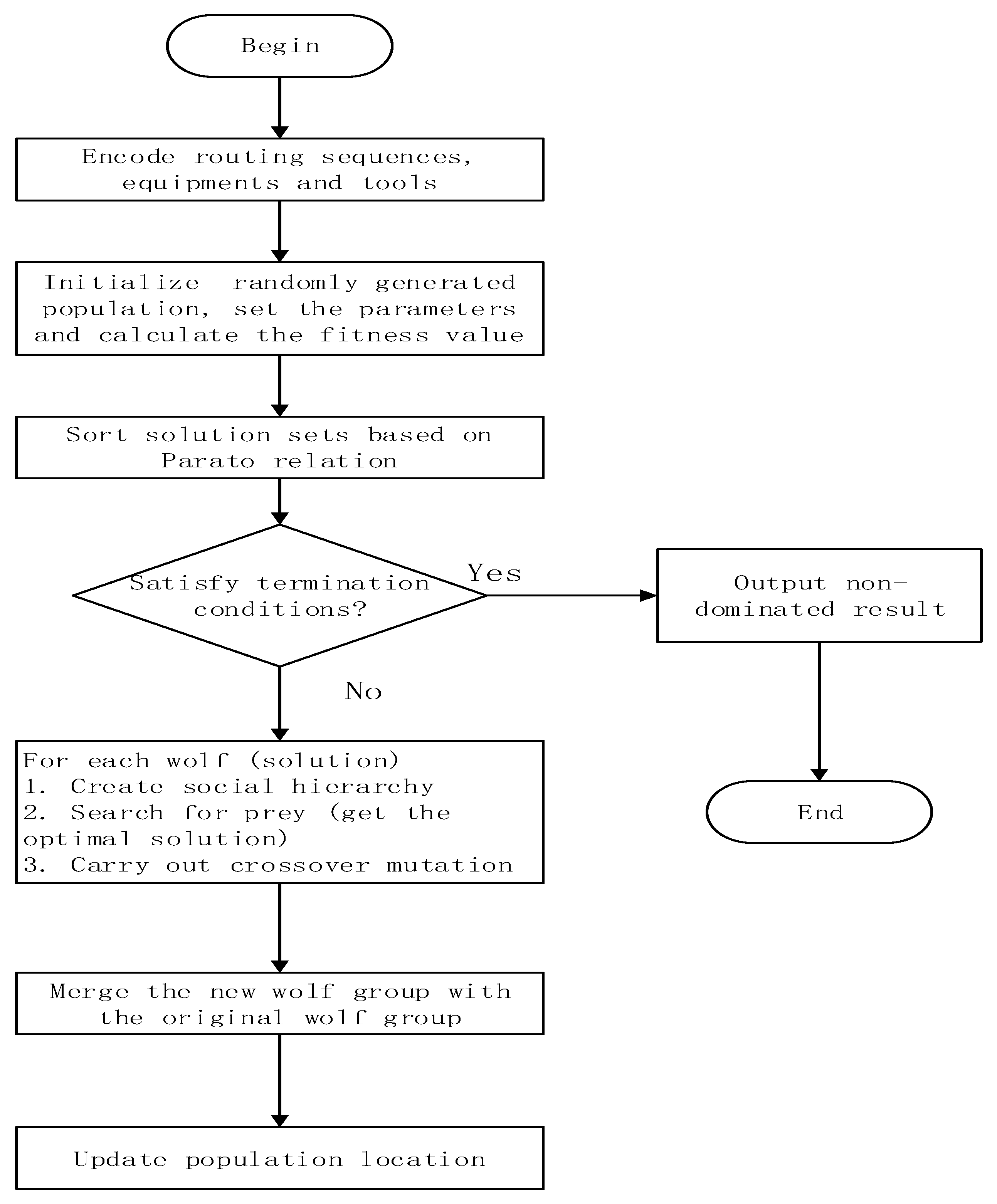
Figure 4.
Individual coding method.

Figure 5.
Sequence substring genetic operation.

Figure 6.
Flow chart of the rolling process.
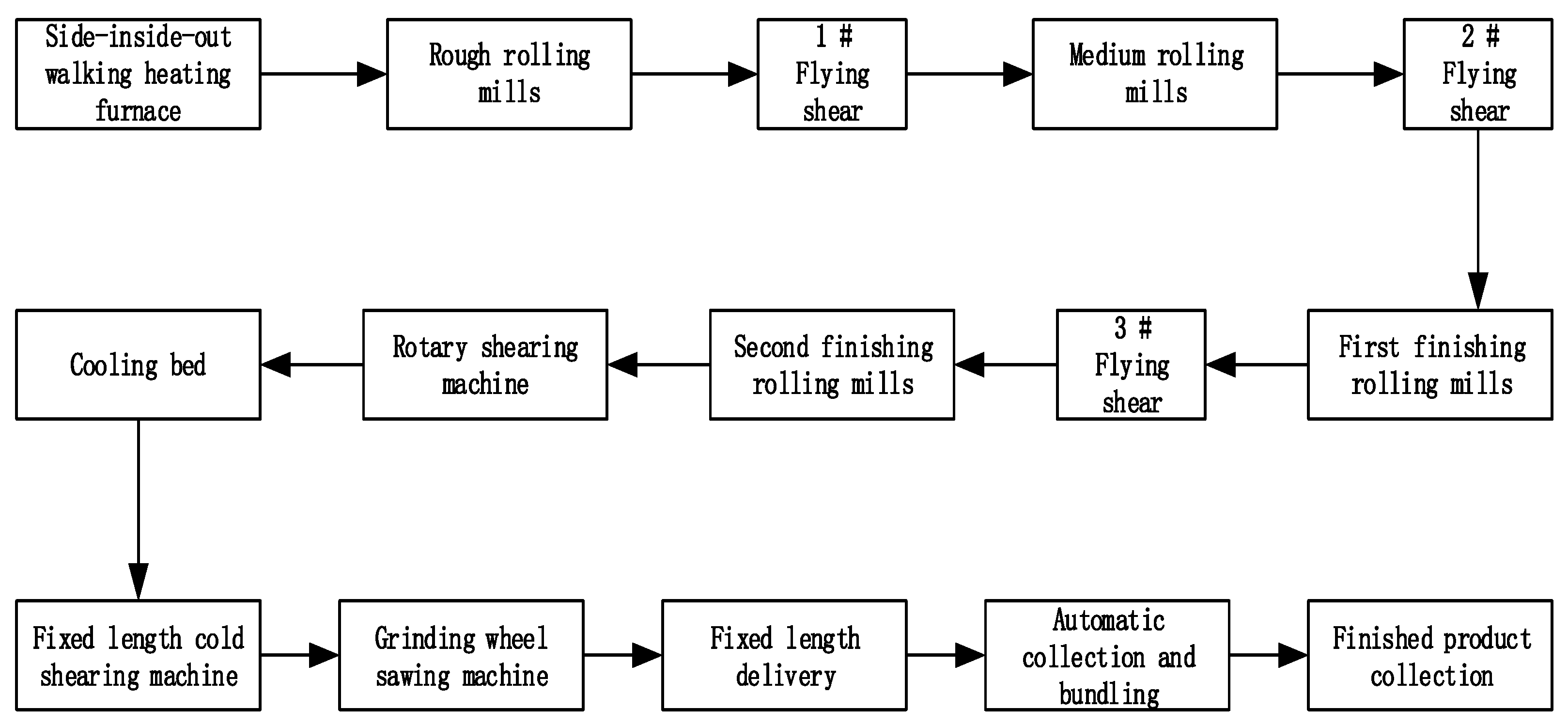
Figure 7.
Iterative convergence graph of blank 1. (a) Energy consumption (b) Carbon emission.

Figure 8.
Iterative convergence graph of blank 2. (a) Energy consumption (b) Carbon emission.

Figure 9.
Iterative convergence graph of blank 3. (a) Energy consumption (b) Carbon emission.

Table 1.
Machine parameters.
| Lathe | |||||||
|---|---|---|---|---|---|---|---|
| M1 | 100 | 1400 | 0.1 | 0.25 | 1700 | 8.0 | 0.85 |
| M2 | 120 | 1600 | 0.1 | 0.35 | 1700 | 10 | 0.8 |
Table 2.
Tool parameters.
| Tool | Material | Main Deflection Angle(°) | Rake Angle(°) | Blade Angle(°) | |
|---|---|---|---|---|---|
| K1 | High-speed steel | 45° | 20° | 5° | 0.8 |
| K2 | Cemented carbide | 45° | 20° | 5° | 0.8 |
Table 3.
Cutting force coefficient.
| 1 | 1750 | 0.9 | 0.75 | 0 | 1 | 580 | 1.1 | 0.65 | 0 | 1 |
| 2 | 2855 | 1.0 | 0.75 | −0.1 | 1 | 2920 | 1 | 0.5 | −0.35 | 1 |
| 1 | 1100 | 0.9 | 0.65 | 0 | 1 | |||||
| 2 | 1930 | 0.9 | 0.6 | −0.35 | 1 |
Table 4.
Values of carbon emission factors in the material preparation process.
| Carbon Emission Category | Material i Consumption | Production Process Consumes Energy c | Energy c Carbon Emission Factor |
|---|---|---|---|
| Steel | Raw coal | 2.653 |
Table 5.
Values of indirect carbon emission factors in the energy preparation process from energy consumption.
Table 5.
Values of indirect carbon emission factors in the energy preparation process from energy consumption.
| Carbon Emission Category | The nth Energy Type Consumed by Energy k | Production Process Consumes Energy | |
|---|---|---|---|
| Electricity | Raw coal | 2.565 | |
| Crude | 2.221 | ||
| Natural gas | 1.642 | ||
| Coal | Crude | 2.221 | |
| Natural gas | 1.642 | ||
| Electricity | 8.220 | ||
| Natural gas | Raw coal | 2.565 | |
| Crude | 2.221 | ||
| Natural gas | 1.642 | ||
| Fuel/Circulating oil/Lubricant | Raw coal | 2.565 | |
| Crude | 2.221 | ||
| Natural gas | 1.642 |
Table 6.
Values of direct carbon emission factors from fossil energy consumption.
| Carbon Emission Category | Consumption Type of Material k | |
|---|---|---|
| Processing direct carbon emissions | Coal | 0.6764 |
| Natural gas | 0.4593 | |
| Fuel/Circulating oil/Lubricant | 0.6878 |
Table 7.
Values of carbon emission factors for waste treatment.
| Carbon Emission Category | Waste l Discharge Type | Energy Consumed Type in the Waste Treatment Process | |
|---|---|---|---|
| Wastewater/waste oil | Electricity | 8.221 | |
| Scra0ps | Electricity | 8.221 |
Table 8.
Comparison of different blank dimensions and optimization objectives.
| Scheme | Blank Dimension | Energy Consumption | Carbon Emission | Material Consumption |
|---|---|---|---|---|
| 1 | 98.6 | 15.865 | 6.31 | 0.893 |
| 2 | 100 | 16.57 | 6.93 | 0.925 |
| 3 | 105 | 17.03 | 6.85 | 1.02 |
Publisher’s Note: MDPI stays neutral with regard to jurisdictional claims in published maps and institutional affiliations. |
© 2022 by the authors. Licensee MDPI, Basel, Switzerland. This article is an open access article distributed under the terms and conditions of the Creative Commons Attribution (CC BY) license (https://creativecommons.org/licenses/by/4.0/).
Share and Cite
MDPI and ACS Style
Xiao, Y.; Zhou, J.; Wang, R.; Zhu, X.; Zhang, H. Energy-Saving and Low-Carbon Gear Blank Dimension Design Based on Business Compass. Processes 2022, 10, 1859. https://doi.org/10.3390/pr10091859
AMA Style
Xiao Y, Zhou J, Wang R, Zhu X, Zhang H. Energy-Saving and Low-Carbon Gear Blank Dimension Design Based on Business Compass. Processes. 2022; 10(9):1859. https://doi.org/10.3390/pr10091859
Chicago/Turabian StyleXiao, Yongmao, Jincheng Zhou, Ruping Wang, Xiaoyong Zhu, and Hao Zhang. 2022. "Energy-Saving and Low-Carbon Gear Blank Dimension Design Based on Business Compass" Processes 10, no. 9: 1859. https://doi.org/10.3390/pr10091859
Note that from the first issue of 2016, this journal uses article numbers instead of page numbers. See further details here.