
Modeling of Erosion in a Cyclone and a Novel Separator with Arc-Shaped Elements

1
Department of Processes and Devices of Chemical Technologies, Nizhnekamsk Institute of Chemistry and Technology, Subdivision of the Kazan National Research Technological University, 423570 Nizhnekamsk, Russia
2
Department of Theoretical Foundations of Heat Engineering, Kazan State Power Engineering University, 420066 Kazan, Russia
3
JSC Taneco, 423570 Nizhnekamsk, Russia
*
Author to whom correspondence should be addressed.
Processes 2023, 11(1), 156; https://doi.org/10.3390/pr11010156
Submission received: 6 November 2022
/
Revised: 27 December 2022
/
Accepted: 31 December 2022
/
Published: 4 January 2023
(This article belongs to the Special Issue Process Control and Smart Manufacturing for Industry 4.0)
Abstract
:Modeling of the separation of catalyst particles from gas using two devices, a cyclone and a novel separator with arc-shaped elements, was performed for fluidized-bed dehydrogenation of C4–C5 paraffins to isoolefins as an example. The proposed dust collector allows one to reduce erosive wear by several times (~6.5-fold) in identical regimes and at identical parameters of the process. The effect of particle size on erosive wear was analyzed under near-industrial conditions; the regions most susceptible to wear in the analyzed devices were identified, as well as the functions describing the dependence between the erosive wear rate and particle diameter for the cyclone and separator with arc-shaped elements, making it possible to predict wear in the devices were obtained.
1. Introduction
Petrochemical companies are paying much attention to the improvement of equipment reliability, reduction of operating expenses, and equipment maintenance. It is particularly relevant for existing dust collection systems [1,2,3,4,5,6,7,8,9], where the fundamental components are cyclones characterized by relatively high performance, as well as simple operating principle and design. Their drawbacks include the relatively high hydraulic drag and susceptibility to abrasive wear of the walls [5,6,7,8]. Thus, cyclones used for coarse and medium-degree gas purification are commonly used in petrochemistry for production lines performing fluidized-bed dehydrogenation of C4–C5 paraffins to isoolefins. A typical feature of these cyclones is that the contact between particles and cyclone walls alters the fractional size distribution of the catalyst due to particle crushing and abrasion [9,10,11,12].
Erosion affecting the upper inlet section and the lower cone of the cyclones is one of the most common problems related to this type of cyclone. F. Fulchini [13] identified the highest-stress areas in the fluidized bed where mechanical strain causes particle abrasion: gas dispensing nozzles, the bubbling layer, cyclones, and bending sections. They also suggested that each of these abrasion sources should be analyzed individually, as there are different abrasion mechanisms (surface abrasion, chipping, and fragmentation). A combination of particle properties and operating conditions, as well as device geometry, are responsible for the predominating mechanism [14,15,16,17]. J. Werther and J. Reppenhagen [18] mentioned that the cyclone is one of the most significant factors contributing to particle abrasion, especially at high flow rates of the surface gas. J. Werther et al. [19] proposed a model of particle abrasion caused by cyclones under conditions of surface particle abrasion for catalyst particles in fluid catalytic cracking (FCC). An analysis of the results revealed that the abrasion rate depended on the material properties, kinetic energy of the gas, and particle size. J. Reppenhagen et al. [20] tested the model reliability by analyzing nine different cyclone geometries. Their model was based on pure abrasion; however, J. Werther et al. [21] mentioned that if the inlet flow rate was increased and/or particle loading was reduced, particles would undergo intensive chipping and/or fragmentation, especially for fresh catalysts [21]. The hydrodynamics of a cyclone (being responsible for the particle speed and residence time) and the physical properties of particles (affecting the dependence between abrasive wear and operating conditions) are factors contributing to abrasive wear in the cyclone at a specified loading of solid particles [22,23]. Numerical modeling using the CFD-DEM approach, with allowance for the dynamics of particles, was performed in these studies.
The gas flow in cyclone separators is usually very unstable and highly swirling. Numerous researchers have studied various geometric and operating parameters using computational methods to enhance cyclone performance [24,25,26,27,28].
A.J. Hoekstra et al. [29] used three turbulence models to study air flows inside a cyclone with three different swirl numbers and recommended employing the Reynolds stress turbulence model (RSM). M.D. Slack et al. [30] used the RSM turbulence model to simulate a gas flow inside the cyclone and revealed that the numerical findings agreed well with the experimental laser Doppler anemometry (LDA) data. G. Gronald and J.J. Derksen [31] applied the large eddy simulation (LES) approach and the two-equation RANS turbulence model to simulate an air flow inside the cyclone and compared the respective CFD results to the experimental findings obtained by LDA. They revealed that the LES model was superior to the RANS model for predicting fluctuating flow rates. However, the LES model requires high-fidelity grids and, therefore, calculations take much time.
Many researchers have emphasized that taking into account the geometric factors is another important problem related to the numerical modeling of flow in cyclones. R.M. Alexander [32] studied some geometric parameters affecting cyclone performance. J. Gimbun et al. [33] investigated the effect of cone tip diameter on pressure drop and cyclone performance.
The literature analysis showed that the problem related to high catalyst consumption due to crushing and abrasion in cyclones has a systemic nature. For cyclones, the most significant factors are the geometric features of the equipment, causing the formation of certain gas-dynamic flow structures affecting the particle–wall interaction. Most studies currently employ numerical simulation of the gas dynamics and particle motion in cyclones using the CFD-DEM model [15,34,35,36,37], which allows one to predict cyclone efficiency, hydraulic drag, etc. at different operating parameters [38,39,40,41]. It should, however, be mentioned that there is sparse research into erosive wear of the cyclone internal surface.
In general, centrifugal cyclones are the reliable and high-performance equipment that allows one to efficiently separate fine particles from the gas medium. However, cyclones of this type are characterized by low wear resistance and are susceptible to cyclone wall erosion [42,43]. Therefore, designing novel separators characterized by low erosive wear can be a useful solution for the industry. A separator with arc-shaped elements (SAE) is the most promising separation device [44]. An advantage of SAE is that it contains specially designed arc-shaped elements that form non-cyclonic flows. It is reasonable and important from both the fundamental and applied standpoints to investigate erosion in the novel device.
This study aimed to compare erosive wear of the proposed separator with arc-shaped elements and the cyclone for removing solid catalyst particles from gases using numerical CFD-DEM modeling and reveal the features of separation conducted in the novel separator.
2. Experimental Procedure
A standard device for collecting solid particles, the centrifugal cyclone (TsN-15), that is employed for the dehydrogenation of isoparaffins at petrochemical plants (Figure 1), and the novel separator with arc-shaped elements proposed for replacing the conventional cyclone were used to study the erosive wear (Figure 2).
The operating principle of a cyclone is widely known. The dust-laden flow enters the chamber through the inlet (1). The dust-laden medium then moves with a tornado-like helical flow pattern. Centrifugal forces make particles leave the flow and collide with the internal wall of the cylindrical cyclone body. The particles then fall into the hopper through the orifice (2). The purified gas leaves the cyclone through the outlet of the dipleg (3) submerged into the cyclone to a certain depth (Figure 1).
The separator with arc-shaped elements has a simple design: it consists of several rows of arc-shaped elements (2) enclosed in the body (3) having a rectangular trapezoid shape. The arc-shaped elements inside the SAE are arranged at an angle of 30°, thus ensuring identical flow motion. To prevent loosening of the arc-shaped elements (2) as the gas flow moves, they are attached to the separator body on both sides. In the upper part of the separator, the arc-shaped elements are inserted into special slots in the internal wall of the separator body (3). In the lower part of the device, they are attached to the grid, where the hopper (4) begins (Figure 2).
The operating principle of SAE is that a wavy structure of dust-laden gas flow is generated, giving rise to a high centrifugal field in which the particles are thrown back to the separator walls and gradually settled in the hopper (4).
Numerical simulation of erosive wear in the separator with arc-shaped elements and the cyclone was performed using the ANSYS Fluent software. The k-w SST turbulence model was used for numerical simulation. When solving this model, partial differential equations (the Navier–Stokes equation) were also set:
where ∇ is the Del operator; ∆ is the Laplacian vector operator; t is time, s; is the coefficient of kinematic viscosity, m2/s; ρ is the gas density, kg/m3; p is pressure, Pa; is the velocity vector field; and is the vector field of bulk forces.
The Navier–Stokes equation was supplemented with the continuity equation:
The discrete phase model (DPM), taking into account the effect of solid particles on the gas flow, was used for modeling. The following equation was applied:
where FD is the drag force, Ntrajct; is the gas flow rate, m/s; is the particle speed, m/s; g is the acceleration due to gravity, m/s2; ρp is the density of particles, kg/m3; and Fx are the additional forces, Ntrajct.
The erosive wear of the devices was calculated using the equation [45]:
where Gp is the mass flow rate of particles, kg/s; C(dp) is the function of particle diameter; f(α) is the function of collision angle; is the particle impact rate, m/s; n is the number indicating the particle impact rate; and Aface is the surface area of a near-wall cell, m2.
When building the 3D cyclone model, the geometric parameters were assumed to be as follows: cylindrical body diameter, 800 mm; height, 4000 mm; inlet, 500 × 180 mm, outlet diameter; 480 mm; and lower orifice diameter, 240 mm. The cyclone was made of steel of AISI 321 grade (Figure 1).
When building the 3D model of the separator with arc-shaped elements, the geometric parameters were assumed to be as follows: device length, 2500 mm; height, 910 mm; width, 900 mm; thickness of the device walls, 10 mm; the size of arc-shaped elements, 76 × 4 mm; the number of rows of arc-shaped elements, 8; the number of elements per row, 6 (Figure 2). H-shaped elements were studied in refs. [46,47,48]; however, the hydraulic drag of the separator with this type of elements was higher compared to that of the device with arc-shaped elements.
The boundary and initial conditions were closest to those used in industrial-scale dehydrogenation of paraffin hydrocarbons. The volumetric flow rate of gas = 1.7 m3/s was set at the device inlet. Pressure of 58,839.9 Pa (0.6 kgf/cm2) was set at the outlet for purified gas and the outlet orifice for the catalyst entering the hopper. The gas flow temperature was assumed to be 550 °C. The standard aluminum–chromium catalyst particles were used. Particle size varied from 20 to 160 µm; particle density was 1400 kg/m3. Table 1 shows the mass flow rates of particles depending on their size.
3. Results and Discussion
To provide the empirical foundations for studying erosion and verify the model, we conducted six experiments with varied sizes of catalyst particles (20–160 µm) and flow rates at a varied (assessed) erosive wear rate (0–1.0; 0–5.0; 0–10.0, and 0–15.0 mm/year). The gas flow rate, pressure, and temperature inside the devices was assumed to be constant upon modeling.
The simulated data are shown in Figure 3, Figure 4, Figure 5, Figure 6, Figure 7, Figure 8 and Figure 9.
3.1. Assessing the Velocity, Pressure, and Temperature Profiles
Figure 3 and Figure 4 show the comparative data on the pressure, velocity, and temperature profiles. According to these data, one can see that increased eddy velocities and pressures are generated at the cyclone margin, thus causing turbulent gas flow and increasing hydraulic drag. Elevated temperatures were also observed in the conical section of the cyclone. Most likely, it occurs due to friction of coarse particles exposed to centrifugal force (Figure 3). Changes in the pressure and velocity profiles for SAE (Figure 4) occur in a regular manner, and no critical deviations were observed. Unlike in the cyclone, the gas flow rate in SAE is stable. Temperature at the device outlet was slightly increased because of centrifugal forces.
3.2. Numerical Investigation of Erosion for the Cyclone
The results of the studies proved that there is significant erosive wear on the cyclone walls in the component of the technological line of paraffin dehydrogenation (>15 mm/year). As a result, holes appear in certain areas of the cyclones, thus increasing catalyst consumption, as well as causing a pressure drop in the technological line and jeopardizing the environment and health of plant employees. Several cyclones arranged in series in a parallel manner (2, 4, 6, and more cyclones) are most commonly used to increase efficiency of gas purification [48,49]. However, the problem of wear remains as proved by the fact that cyclones are frequently repaired and replaced. The highly loaded first-stage cyclone separators are usually more susceptible to erosive wear in their upper part, starting at the inlet and ending at the lower cylindrical section of the cyclone. The lower part of the cyclone cone is almost not subjected to erosive wear (Figure 5). The reason for that is the scheme of gas flow in the cyclone. After the solid catalyst particles are knocked out of the swirling flow towards the cyclone walls in the upper part of the device, gravity starts playing the key role. As a result, solid particles quickly fall down to the cyclone bottom and almost do not contact the cyclone cone.
Numerical modeling of the separator with arc-shaped elements has shown that, unlike for the cyclone, the separator walls are much less prone to erosive wear (≤2.31 mm/year). The lower annual erosion rate in the proposed separator compared to that in the cyclone can be attributed to differences in the flow structure. However, separation of particles from the gas occurs in both devices mostly due to centrifugal forces. For the wave-like flow structure, particles are thrown to different areas of the separator walls more chaotically, so the erosive wear rate is reduced. The presence of several rows of arc-shaped elements allows one to replace the worn-out elements when necessary.
It was found experimentally that the erosive wear rate depends on particle diameter in both devices. The erosive wear rate goes up as particle diameter is increased from 20 to 160 µm. Variation of catalyst particle size can alter the erosive wear rate in different cyclone regions. Thus, the inlet area and the upper cylindrical part of the cyclone are most susceptible to erosive wear from particles with a diameter of 20–40 µm. As particle size increases from 40 to 160 µm, erosive wear starts to be observed in the lower cylindrical part of the cyclone as well. It is caused by particle coarseness. After being knocked out of the structured swirling flow, particles fall down, but they are constantly and repeatedly thrown to the device walls due to the eddy existing along the entire length of the cylindrical part of the cyclone. Therefore, pressure applied to the lower cylindrical part of the cyclone and the erosive wear rate increase at larger particle sizes (Figure 5).
3.3. Assessment of the Gas Flow Structure for the Novel Separator with Arc-Shaped Elements
Figure 6 shows the wave-like flow structure. The ordered arrangement of the eddy structure without chaotic swirl motion allows one to minimize the pickup of particles previously separated from the flow back into it.
The dust-laden gas flow enters the separator with arc-shaped elements through the inlet (1). The flow runs into the space between the rows of arc-shaped elements (2). The elements are arranged in a checkerboard pattern. Along with the checkerboard pattern of arrangement of arc-shaped element rows (2), there is an important design feature related to their arrangement with respect to each other. In particular, the following condition is met: the elements are arranged in such a manner that it is possible, starting at the central point of the circle (that is equal to two united arc-shaped elements), to draw a circle equal to two of its diameters and running through the central points of the straight outermost margin (the adjacent elements located in the preceding and subsequent rows). The fulfilment of this condition provides the most efficient wave-like structure of gas flow motion, since the centrifugal forces are maximal for this arrangement [41].
The wave-like flow structure is generated as the dust-laden gas goes around the large number of rows of arc-shaped elements (2) arranged in a checkerboard pattern. During the gas motion, there emerge many points of centrifugal forces in each eddy (turn). The high centrifugal forces are caused by the small diameter of semi-circles. Under the centrifugal forces, particles are knocked out of the structured flow towards the walls of the arc-shaped elements (2) and fall down into the hopper (4). The purified gas flow leaves the separator with arc-shaped elements through the outlet (5) (Figure 2).
The absence of rectilinear or nearly rectilinear particle motion towards the device walls and further contact with the walls as the dust-laden flow passes through the separator substantially minimizes the erosive wear.
3.4. Numerical Investigation of Erosion for the Separator with Arc-Shaped Elements
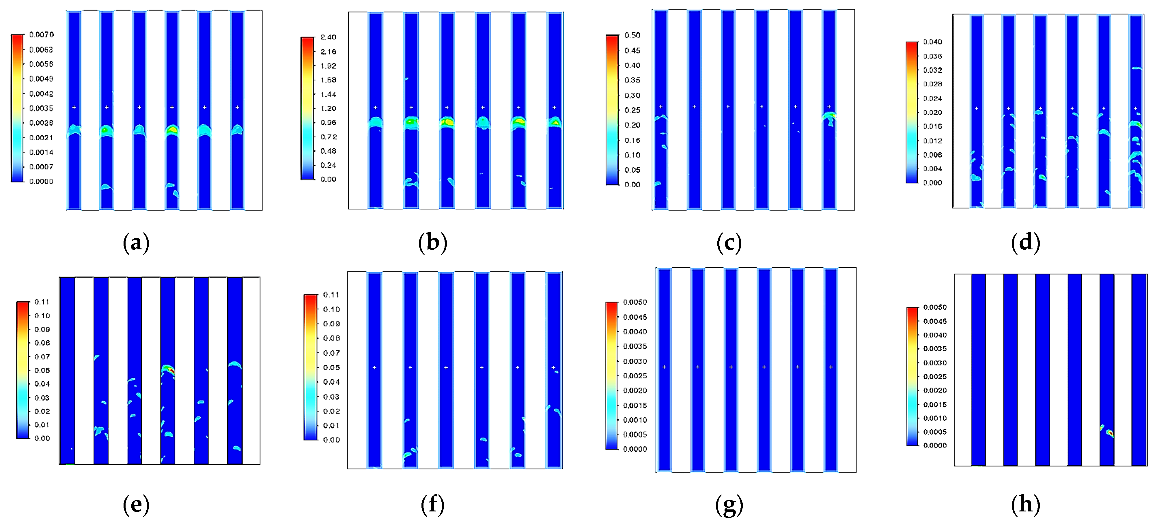
Numerical modeling of erosive wear in the separator with arc-shaped elements showed that the first two rows of elements were most susceptible to erosion. It was presumably caused by the incompletely formed structure of the dust-laden medium in the proposed device. In particular, the structure became fully wave-like in the zone located within the first two rows of the arc-shaped elements (Figure 6). However, some particles did not have enough time to be rearranged along with the gas and inertially move in a rectilinear manner towards a certain area of the walls of the first two rows of arc-shaped elements, thus causing greater erosive wear of these elements compared to the other rows (Figure 7 and Figure 8).
An analysis of the erosive wear patterns shown in Figure 7 and Figure 8 (the catalyst particle diameter (dp) in the gas flow being 20 and 160 µm, respectively) demonstrates that the erosive wear area on the walls of the arc-shaped elements increased with rising particle diameter. It is clearly seen by examining the first two rows of arc-shaped elements. At a particle diameter of 20 µm, the peripheral regions of arc-shaped elements were more susceptible to erosion. At 160 µm, erosion was observed in certain areas of the arc-shaped elements along the entire perimeter. It is also evident by comparing rows 3–5 of the arc-shaped elements at a particle diameter of 20 and 160 µm (Figure 7 and Figure 8).
The maximum erosive wear rates of the rows of elements in the separator with arc-shaped elements at particle diameters ranging from 20 to 160 µm were digitized during numerical modeling. In Table 2, the first two columns correspond to the two rows of arc-shaped elements that had undergone the maximum erosion at each analyzed catalyst particle diameter. One can see that in this range of particle diameters (20–160 µm), the first two rows of arc-shaped elements are characterized by the maximum erosion rate, which proves the statement given above. For rows 7 and 8, there is almost no wear of the arc-shaped elements, which may indicate that particle concentration in the gas was relatively low (Table 2).
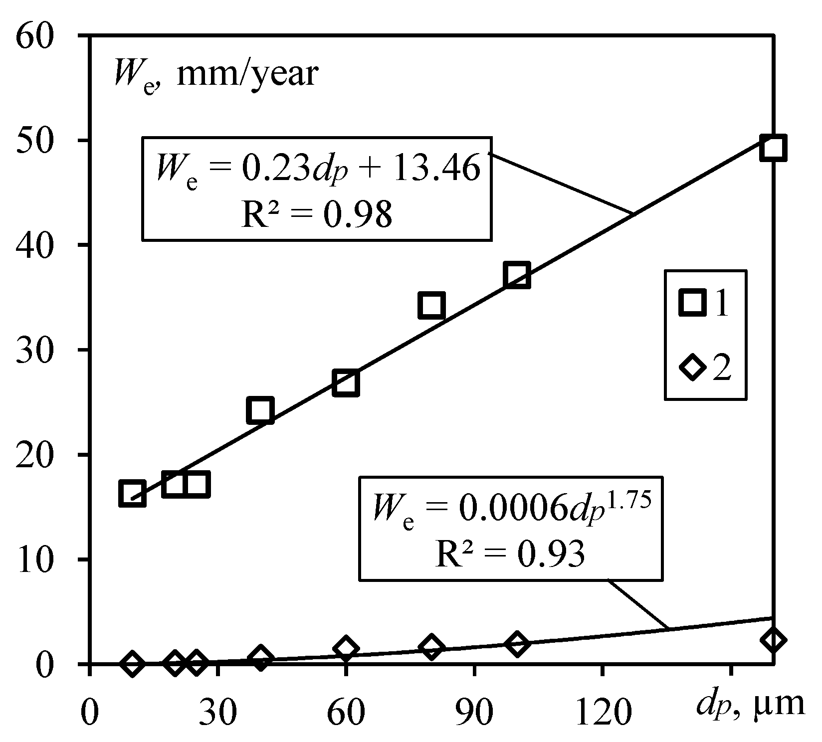
Figure 4, Figure 7 and Figure 8 show that the erosive wear rate of the cyclone was significantly higher than that for separators with arc-shaped elements. Figure 9 shows it in a more systematized manner. As particle diameter increases from 20 to 160 µm, the erosive wear rate of the cyclone is most accurately described by linear function with the mean square deviation of 0.98:
The erosive wear rate of the separator with arc-shaped elements is most accurately described by the power-law function with the mean square deviation of 0.93:
Numerical experiments demonstrate that the continuous impact of the high-speed flow of solid catalyst particles on the walls of the devices after the particles were knocked out of the dust-laden medium leads to gradual formation of micro- and macro-defects, which can manifest themselves as roughness, pits, cavities, holes, and other wall defects. As mentioned previously, it increases the catalyst consumption and causes a pressure drop in the technological line and other negative effects.
The study has predicted that using the cyclone for one year for collecting catalyst particles sized 20–160 µm will most likely cause the formation of holes, since erosive wear is more than 15 mm/year. For the wave-like flow structure in the separator with arc-shaped elements, at the volumetric flow rate of 1.7 m3/s, the erosive wear rate was no higher than 2.31 mm. For cyclone walls thicker than 3 mm, it is highly likely that arc-shaped elements will remain undamaged.
In the separator with arc-shaped elements, erosive wear affects the elements rather than the separator body; therefore, the probability of erosive wear of the body of the proposed separator and excessive catalyst losses is minimized.
4. Conclusions
Modeling of the separation of catalyst particles from the gas using two devices (a cyclone and a separator with arc-shaped elements) revealed that the proposed dust collector allows one to reduce the erosive wear by several times (6.5-fold) for identical operating modes and operating parameters (temperature, pressure, particle size and speed, etc.). The lower erosive wear in the novel separator compared to that in a cyclone is caused by the ordered wave-like flow structure at which particles are thrown into different regions of SAE elements with a greater intensity during eddy formation, so the equipment-damaging side processes are mitigated. A unique feature of the SAE compared to other centrifugal separators is that higher-intensity centrifugal forces are generated in it. Many points of eddy formation appear, with eddy radius being relatively small, as the gas passes around the arc-shaped elements, making particle separation from gas flows more efficient.
It has been demonstrated that the wall erosion rate rises with increasing average size of catalyst particles (>40 µm) for both analyzed devices. Whereas in the presence of particles sized up to 40 µm only the upper part of the cyclone was mainly susceptible to erosive wear, at larger particle size, wall erosion starts to be observed both in the upper part and the lower cylindrical part of the cyclone due to particle coarseness and their chaotic collisions with the device body during settling.
In the separation device with arc-shaped elements, the first two rows of elements are most susceptible to erosion. This is caused by the incomplete formation of the structure of the dust-laden medium in the front part of the device. As a result of rectilinear and inertial motion, particles enter into the same zones within the first two rows of the arc-shaped elements. For the proposed separator, arc-shaped elements undergo erosive wear, thus preventing the formation of holes in the device body and catalyst loss.
The functions showing the dependence between the erosive wear rate and particle diameter for the cyclone and the separator with arc-shaped elements have been obtained; these functions allow one to predict wear of the devices. Speaking about the future outlook, the separator with arc-shaped elements can be recommended to be used at petrochemical plants, and in such processes as fluidized-bed dehydrogenation of C4–C5 isoparaffins to isoolefins in particular.
Author Contributions
All authors listed have made a substantial, direct and intellectual contribution to the work, and approved it for publication: Conceptualization: E.I.S., V.E.Z., A.V.D. and I.I.S.; Investigation: E.I.S. and V.E.Z.; Writing: E.I.S.., V.E.Z. and A.V.D.; writing—review and editing E.I.S., V.E.Z., A.V.D. and I.I.S.; data curation, E.I.S. and V.E.Z.; visualization—V.E.Z.; project administration—I.I.S. All authors have read and agreed to the published version of the manuscript.
Funding
This research received no external funding.
Data Availability Statement
Data are available at request from the authors.
Conflicts of Interest
The authors declare no conflict of interest.
References
- Zinurov, V.E.; Dmitriev, A.V.; Kharkov, V.V. Design of High-Efficiency Device for Gas Cleaning from Fine Solid Particles. In Proceedings of the 6th International Conference on Industrial Engineering, Delhi, India, 18–19 June 2021; pp. 378–385. [Google Scholar] [CrossRef]
- Lim, J.-H.; Oh, S.-H.; Kang, S.; Lee, K.-J.; Yook, S.-J. Development of cutoff size adjustable omnidirectional inlet cyclone separator. Sep. Purif. Technol. 2021, 276, 1–9. [Google Scholar] [CrossRef]
- Fu, P.; Zhu, J.; Li, Q.; Cheng, T.; Zhang, F.; Huang, Y.; Ma, L.; Xiu, G.; Wang, H. DPM simulation of particle revolution and high-speed self-rotation in different pre-self-rotation cyclones. Powder Technol. 2021, 394, 290–299. [Google Scholar] [CrossRef]
- Yu, G.; Dong, S.; Yang, L.; Yan, D.; Dong, K.; Wei, Y.; Wang, B. Experimental and numerical studies on a new double-stage tandem nesting cyclone. Chem. Eng. Sci. 2021, 236, 1–14. [Google Scholar] [CrossRef]
- Farzad, P.; Seyyed, H.H.; Khairy, E.; Goodarz, A. Numerical investigation of effects of inner cone on flow field, performance and erosion rate of cyclone separators. Sep. Purif. Technol. 2018, 201, 223–237. [Google Scholar]
- Celis, G.E.O.; Loureiro, J.B.R.; Lage, P.L.C.; Freire, A.P.S. The effects of swirl vanes and a vortex stabilizer on the dynamic flow field in a cyclonic separator. Chem. Eng. Sci. 2022, 248, 1–45. [Google Scholar] [CrossRef]
- Haig, C.W.; Hursthouse, A.; Mcilwain, S.; Sykes, D. An empirical investigation into the influence of pressure drop on particle behaviour in small scale reverse-flow cyclones. Powder Technol. 2015, 275, 172–181. [Google Scholar] [CrossRef]
- Haake, J.; Oggian, T.; Utzig, J.; Rosa, L.M.; Meier, H.F. Investigation of the pressure drop increase in a square free-vortex cyclonic separator operating at low particle concentration. Powder Technol. 2020, 374, 1–21. [Google Scholar] [CrossRef]
- Zhang, Y.; Jiang, Y.; Xin, R.; Yu, G.; Jin, R.; Dong, K.; Wang, B. Effect of particle hydrophilicity on the separation performance of a novel cyclone. Sep. Purif. Technol. 2020, 237, 1–11. [Google Scholar] [CrossRef]
- Chang, Y.-L.; Jiang, X.; Li, J.-P.; Fu, P.-B.; Yuan, W.; Xin, R.-K.; Huang, Y.; Wang, H.-L. Inlet particle-sorting cyclones configured along a spiral channel for the enhancement of PM2.5 separation. Sep. Purif. Technol. 2021, 257, 1–13. [Google Scholar] [CrossRef]
- Seyed Masoud, V.; Farzad, P.; Kamali, M.; Jebeli, H.J. Numerical Investigation of the Impact of Inlet Channel Numbers on the Flow Pattern, Performance, and Erosion of Gas-particle Cyclone. Chem. Eng. Iran. J. Oil Gas Sci. Technol. 2018, 7, 59–78. [Google Scholar]
- Basaran, M.; Erpul, G.; Uzun, O.; Gabriels, D. Comparative efficiency testing for a newly designed cyclone type sediment trap for wind erosion measurements. Geomorphology 2011, 130, 343–351. [Google Scholar] [CrossRef]
- Fulchini, F. Particle Attrition in Circulating Fluidised Bed Systems. Ph.D. Dissertation, University of Leeds, Leeds, UK, 2020; p. 298. [Google Scholar]
- Welt, J.; Lee, W.; Krambeck, F.J. Catalyst attrition and deactivation in fluid catalytic cracking system. Chem. Eng. Sci. 1977, 32, 1211–1218. [Google Scholar] [CrossRef]
- Fu, P.; Yu, H.; Li, Q.; Cheng, T.; Zhang, F.; Huang, Y.; Lv, W.; Xiu, G.; Wang, H. CFD-DEM simulation of particle revolution and high-speed self-rotation in cyclones with different structural and operating parameters. Chem. Eng. J. Adv. 2021, 8, 1–13. [Google Scholar] [CrossRef]
- Li, Q.; Wang, J.; Xu, W.; Zhang, M. Investigation on separation performance and structural optimization of a two-stage series cyclone using CPFD and RSM. Adv. Powder Technol. 2020, 31, 3706–3714. [Google Scholar] [CrossRef]
- Azri, M.; Nor, M.; Shahrul, K.; Alemu, L.T. Numerical investigation of API 31 cyclone separator for mechanical seal piping plan for rotating machineries. Alex. Eng. J. 2022, 61, 1597–1606. [Google Scholar] [CrossRef]
- Werther, J.; Reppenhagen, J. Catalyst Attrition in Fluidized-Bed Systems. AIChE J. 1999, 45, 2001–2010. [Google Scholar] [CrossRef]
- Werther, J.; Xi, W. Jet attrition of catalyst particles in gas fluidized beds. Powder Technol. 1993, 76, 39–46. [Google Scholar] [CrossRef]
- Reppenhagen, J.; Werther, J. Catalyst attrition in cyclones. Powder Technol. 2000, 113, 55–69. [Google Scholar] [CrossRef]
- Werther, J.; Reppenhagen, J. Attrition. In Handbook of Fluidization and Fluid-Particle Systems; Yang, W., Ed.; CRC Press: Boca Raton, FL, USA, 2003. [Google Scholar]
- Ghadiri, M.; Cleaver, J.A.S.; Tuponogov, V.G.; Werther, J. Attrition of FCC powder in the jetting region of a fluidized bed. Powder Technol. 1994, 80, 175–178. [Google Scholar] [CrossRef]
- Haig, C.W.; Hursthouse, A.; McIlwain, S.; Sykes, D. The effect of particle agglomeration and attrition on the separation efficiency of a Stairmand cyclone. Powder Technol. 2014, 258, 110–124. [Google Scholar] [CrossRef]
- Griffiths, W.D.; Boysan, F. Computational fluid dynamics (CFD) and empirical modelling of the performance of a number of cyclone samplers. J. Aerosol Sci. 1996, 27, 281–304. [Google Scholar] [CrossRef]
- Gimbun, J.; Chuah, T.G.; Choong, T.S.Y.; Fakhru’l-Razi, A. A CFD study on the prediction of cyclone collection efficiency. Int. J. Comp. Meth-Sing. 2005, 6, 161–168. [Google Scholar] [CrossRef]
- Gimbun, J.; Chuah, T.G.; Fakhru’l-Razi, A.; Choong, T.S.Y. The influence of temperature and inlet velocity on cyclone pressure drop: A CFD study. Chem. Eng. Process 2005, 44, 7–12. [Google Scholar] [CrossRef]
- Elsayed, K.; Lacor, C. Optimization of the cyclone separator geometry for minimum pressure drop using mathematical models and CFD simulations. Chem. Eng. Sci. 2010, 65, 6048–6058. [Google Scholar] [CrossRef]
- Park, D.; Go, S.J. Design of Cyclone Separator Critical Diameter Model Based on Machine Learning and CFD. Processes 2020, 8, 1521. [Google Scholar] [CrossRef]
- Hoekstra, A.J.; Derksen, J.J.; Van, H.E.A.; Akker, D. An experimental and numerical study of turbulent swirling flow in gas cyclones. Chem. Eng. Sci. 1999, 54, 2055–2065. [Google Scholar] [CrossRef] [Green Version]
- Slack, M.D.; Prasad, R.O.; Bakker, A.; Boysan, F. Advances in cyclone modelling using unstructured grids. Chem. Eng. Res. Des. 2000, 78, 1098–1104. [Google Scholar] [CrossRef]
- Gronald, G.; Derksen, J.J. Simulating turbulent swirling flow in a gas cyclone: A comparison of various modeling approaches. Powder Technol. 2011, 205, 160–171. [Google Scholar] [CrossRef]
- Alexander, R.M. Fundamentals of cyclone design and operation. Proc. Aust. Inst. Miner. Met. 1949, 152, 152–153. [Google Scholar]
- Gimbun, J.; Chuah, T.G.; Choong, T.S.Y.; Fakhru’l-Razi, A. Prediction of the effects of cone tip diameter on the cyclone performance. J. Aerosol Sci. 2005, 36, 1056–1065. [Google Scholar] [CrossRef]
- El-Emam, M.A.; Zhou, L.; Shi, W.; Chen, H. Performance evaluation of standard cyclone separators by using CFD-DEM simulation with realistic bio-particulate matter. Powder Technol. 2021, 385, 357–374. [Google Scholar] [CrossRef]
- Li, H.; Wang, L.; Du, C.; Hong, W. CFD-DEM investigation into flow characteristics in mixed pulsed fluidized bed under electrostatic effects. Particuology 2021, 65, 1–38. [Google Scholar] [CrossRef]
- Nakhaei, M.; Lu, B.; Tian, Y.; Wang, W.; Kim, D.-J.; Wu, H. CFD Modeling of Gas–Solid Cyclone Separators at Ambient and Elevated Temperatures. Processes 2019, 8, 228. [Google Scholar] [CrossRef] [Green Version]
- Li, Z.; Tong, Z.; Yu, A.; Miao, H.; Chu, K.; Zhang, H.; Guo, G.; Chen, J. Numerical investigation of separation efficiency of the cyclone with supercritical fluid-solid flow. Particuology 2022, 62, 36–46. [Google Scholar] [CrossRef]
- Hamed, S.; Mohammad, R.; Dariush, A. Numerical study of flow field in new design cyclones with different wall temperature profiles: Comparison with conventional ones. Adv. Powder Technol. 2021, 32, 3268–3277. [Google Scholar] [CrossRef]
- Chen, J.; Jiang, Z.; Yang, B.; Wang, Y.; Zeg, F. Effect of inlet area on the performance of a two-stage cyclone separator. Chin. J. Chem. Eng. 2021, 36, 1–35. [Google Scholar] [CrossRef]
- Zhang, Z.; Dong, S.; Dong, K.; Hou, L.; Wang, W.; Wei, Y.; Wang, B. Experimental and numerical study of a gas cyclone with a central filter. Particuology 2021, 65, 1–46. [Google Scholar] [CrossRef]
- Mazyan, W.I.; Ahmadi, A.; Brinkerhoff, J.; Ahmed, H.; Hoorfar, M. Enhancement of cyclone solid particle separation performance based on geometrical modification: Numerical analysis. Sep. Purif. Technol. 2018, 191, 276–285. [Google Scholar] [CrossRef]
- Reddy Karri, S.B.; Ray, C.; Knowlton, T. Erosion in Second Stage Cyclones: Effects of Cyclone Length and Outlet Gas Velocity. In Proceedings of the 10th International Conference on Circulating Fluidized Beds and Fluidization Technology-CFB-10, Sun River, OR, USA, 1–5 May 2013; Available online: http://dc.engconfintl.org/cfb10/40 (accessed on 5 October 2022).
- Peukert, W.; Wadenpohl, C. Industrial separation of fine particles with difficult dust properties. Powder Technol. 2001, 118, 136–148. [Google Scholar] [CrossRef] [Green Version]
- Salakhova, E.I.; Dmitriev, A.V.; Zinurov, V.E.; Nabiullin, I.R.; Salakhov, I.I. Dust Collector for Paraffin Dehydrogenation Units with a Fluidized Catalyst Bed. Catal. Ind. 2022, 14, 369–375. [Google Scholar] [CrossRef]
- Edwards, J.K.; McLaury, B.S.; Shirazi, S.A. Evaluation of Alternative Pipe Bend Fittings in Erosive Service. In Proceedings of the ASME FEDSM’00: ASME 2000 Fluids Engineering Division Summer Meeting, Boston, MA, USA, 11–15 June 2000. [Google Scholar]
- Dmitriev, A.V.; Zinurov, V.E.; Dmitrieva, O.S. Collecting of finely dispersed particles by means of a separator with the arc-shaped elements. In Proceedings of the International Conference on Modern Trends in Manufacturing Technologies and Equipment (ICMTMTE 2019), Sevastopol, Russia, 9 September 2019; Volume 126, p. 00007. [Google Scholar] [CrossRef]
- Zinurov, V.E.; Kharkov, V.V.; Salakhova, E.I.; Vakhitov, M.R.; Kuznetsov, M.G. Numerical simulation of collection efficiency in separator with inclined double-T elements. IOP Conf. Ser. Earth Environ. Sci. 2022, 981, 42024. [Google Scholar] [CrossRef]
- Zinurov, V.; Dmitriev, A.; Kharkov, V. Influence of process parameters on capturing efficiency of rectangular separator. In Proceedings of the 2020 International Conference on Information Technology and Nanotechnology (ITNT), Samara, Russia, 26–29 May 2020; pp. 1–4. [Google Scholar] [CrossRef]
- Fu, P.; Jiang, X.; Ma, L.; Yang, Q.; Bai, Z.; Yang, X.; Lv, W. Enhancement of PM2.5 cyclone separation by droplet capture and particle sorting. Environ. Sci. Technol. 2018, 52, 11652–11659. [Google Scholar] [CrossRef] [PubMed]
Figure 1.
A real-world 3D model of the TsN-15 cyclone: (1) the inlet for the gas contaminated by the catalyst; (2) the outlet for catalyst particles collected during purification; and (3) the outlet for purified gas.
Figure 1.
A real-world 3D model of the TsN-15 cyclone: (1) the inlet for the gas contaminated by the catalyst; (2) the outlet for catalyst particles collected during purification; and (3) the outlet for purified gas.

Figure 2.
A separator with arc-shaped elements (a cross-sectional view): (1) the inlet for the gas contaminated by the catalyst; (2) rows of arc-shaped elements; (3) the body; (4) the hopper; and (5) the outlet for purified gas.
Figure 2.
A separator with arc-shaped elements (a cross-sectional view): (1) the inlet for the gas contaminated by the catalyst; (2) rows of arc-shaped elements; (3) the body; (4) the hopper; and (5) the outlet for purified gas.
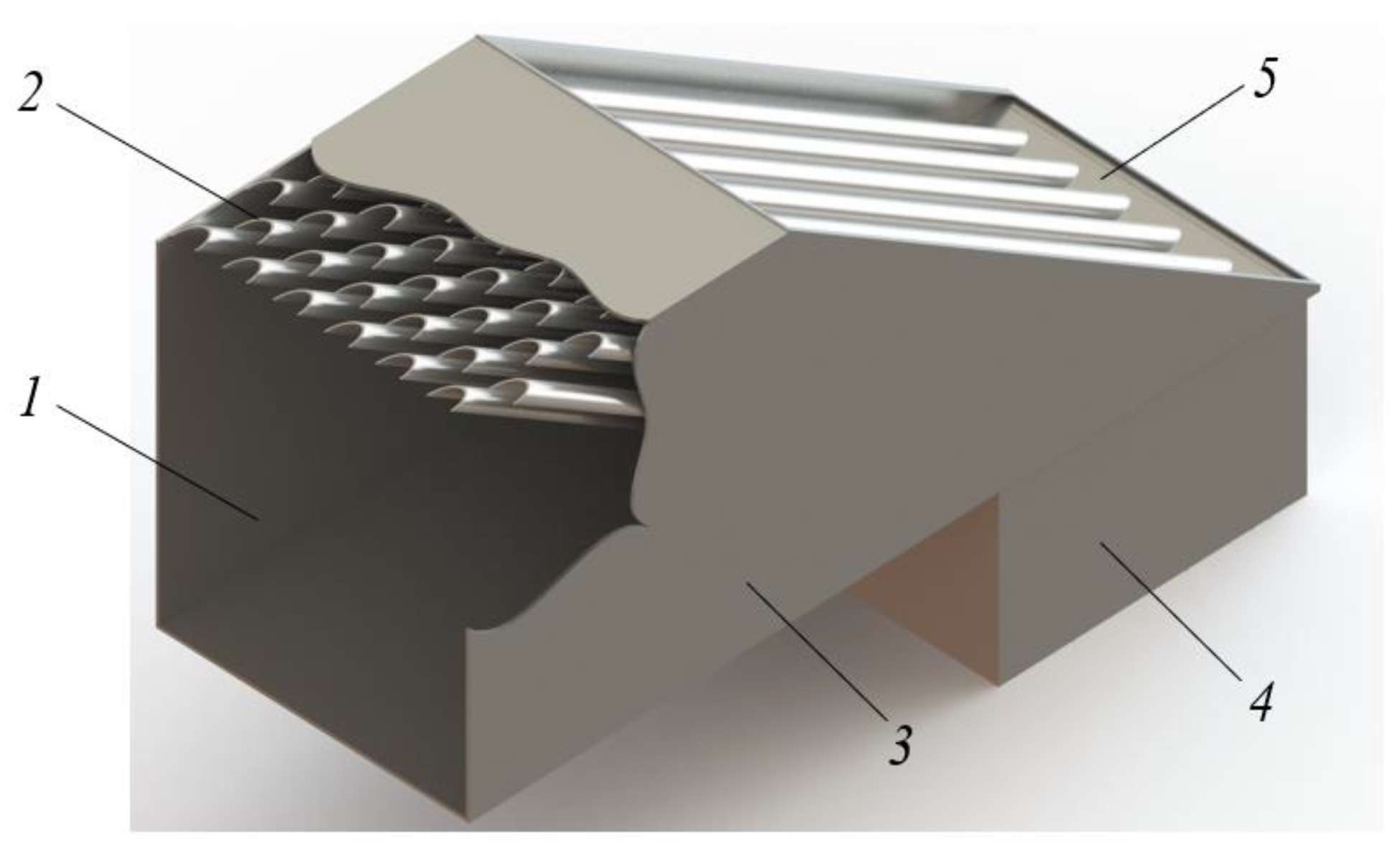
Figure 3.
The data on the (a) pressure, (b) velocity, and (c) temperature profiles for the cyclone.
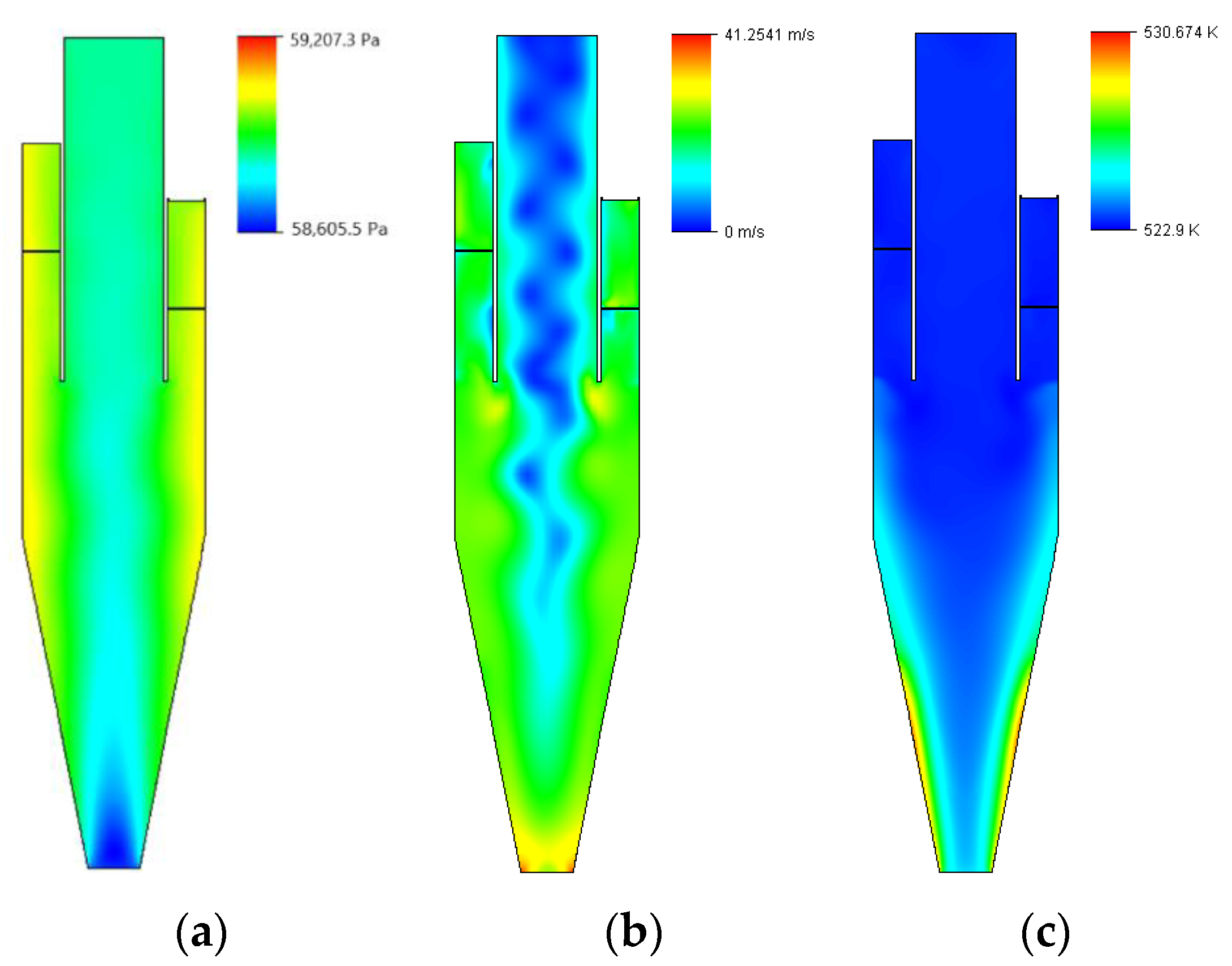
Figure 4.
The data on the (a) pressure, (b) velocity, and (c) temperature profiles for the separator with arc-shaped elements.
Figure 4.
The data on the (a) pressure, (b) velocity, and (c) temperature profiles for the separator with arc-shaped elements.
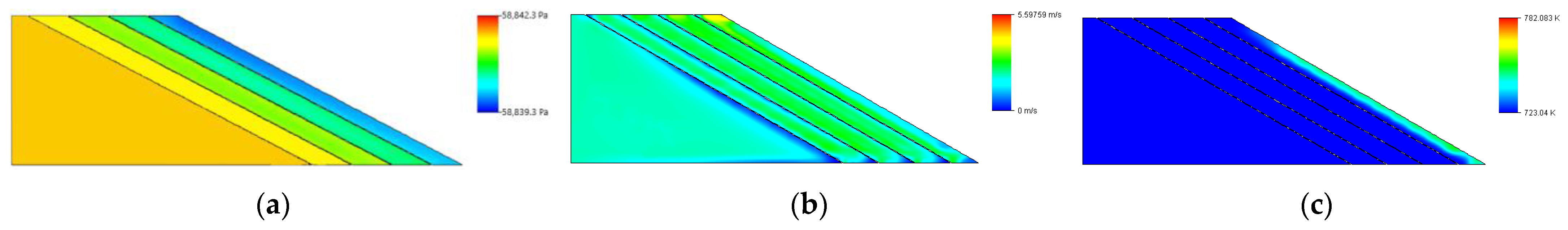
Figure 5.
Erosive wear regions in the cyclone at different particle diameters (dp). The legend shows the numeric value of the erosive wear rate We, mm/year: 0–1.0 mm/year; 0–5.0 mm/year; 0–10.0 mm/year; and 0–15.0 mm/year. (a) dp = 20 µm. (b) dp = 25 µm. (c) dp = 40 µm. (d) dp = 60 µm. (e) dp = 100 µm. (f) dp = 160 µm.
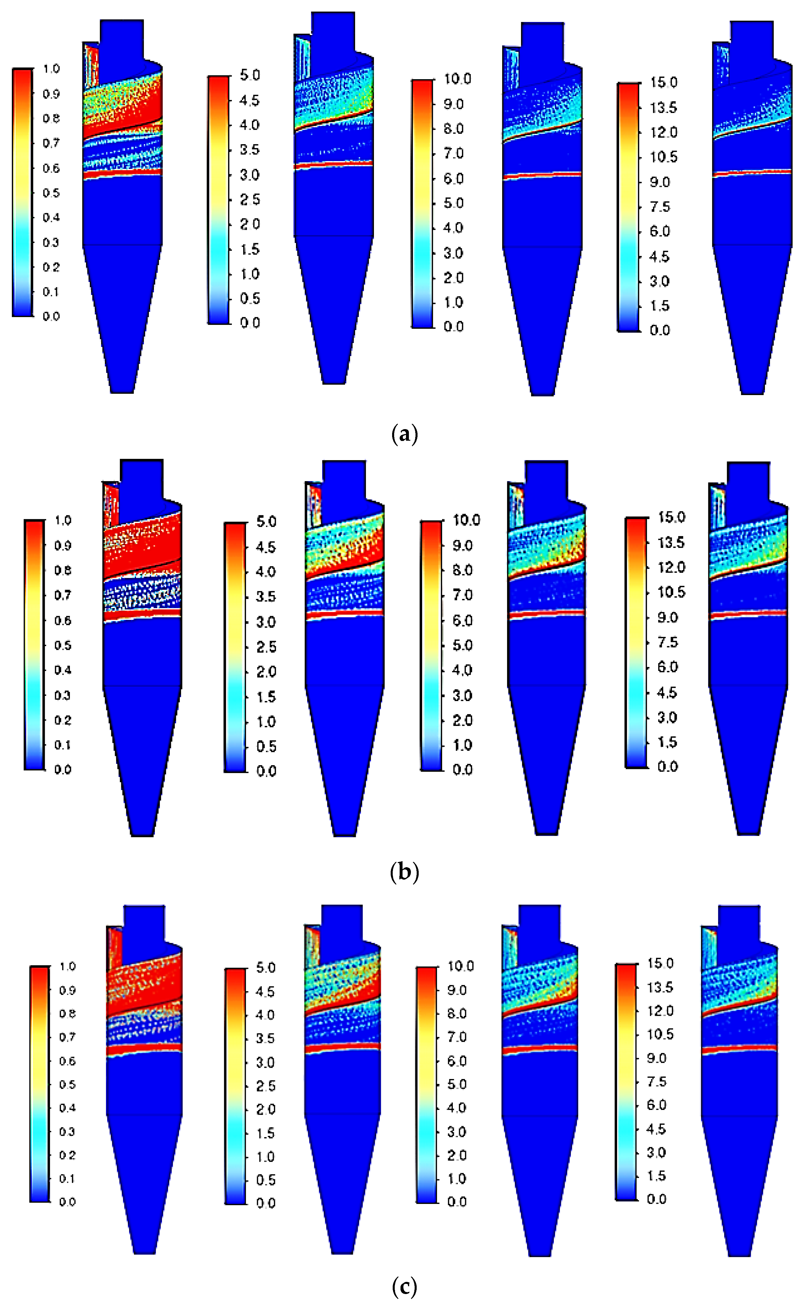
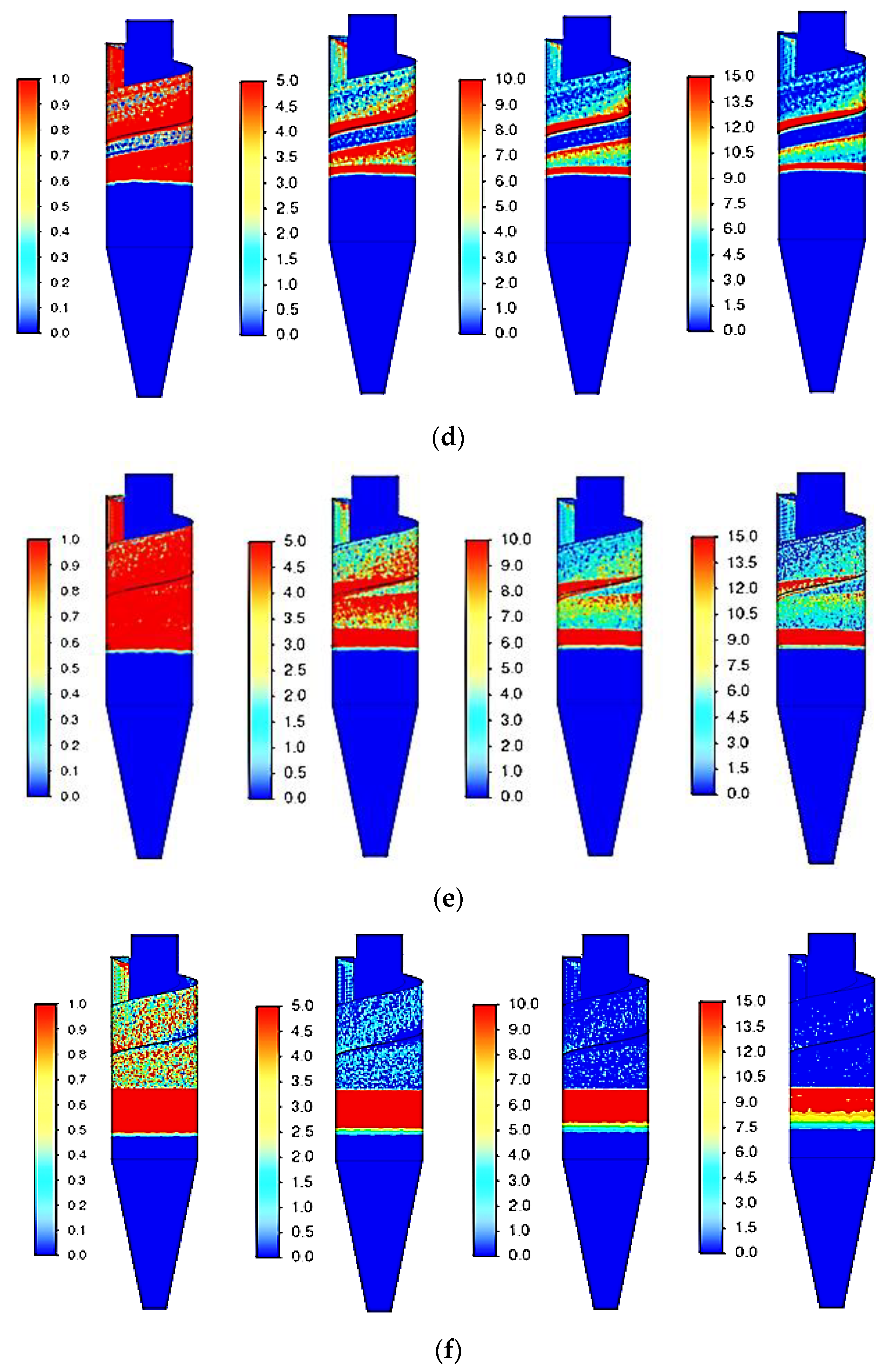
Figure 6.
The wave-like structure of the gas flow inside a separator with arc-shaped elements. The vector field of velocities was recorded for the midplane perpendicular to the separator inlet.
Figure 6.
The wave-like structure of the gas flow inside a separator with arc-shaped elements. The vector field of velocities was recorded for the midplane perpendicular to the separator inlet.
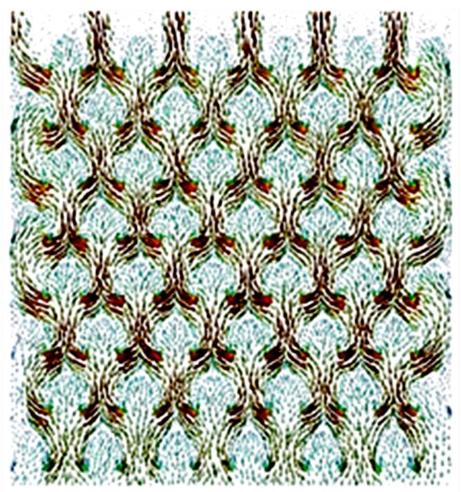
Figure 7.
The regions of erosive wear rates We, mm/year for different rows of arc-shaped elements in the separator at particle diameter dp = 20 µm (frontal view, as seen from the inlet). (a) row 1. (b) row 2. (c) row 3. (d) row 4. (e) row 5. (f) row 6. (g) row 7. (h) row 8.
Figure 7.
The regions of erosive wear rates We, mm/year for different rows of arc-shaped elements in the separator at particle diameter dp = 20 µm (frontal view, as seen from the inlet). (a) row 1. (b) row 2. (c) row 3. (d) row 4. (e) row 5. (f) row 6. (g) row 7. (h) row 8.
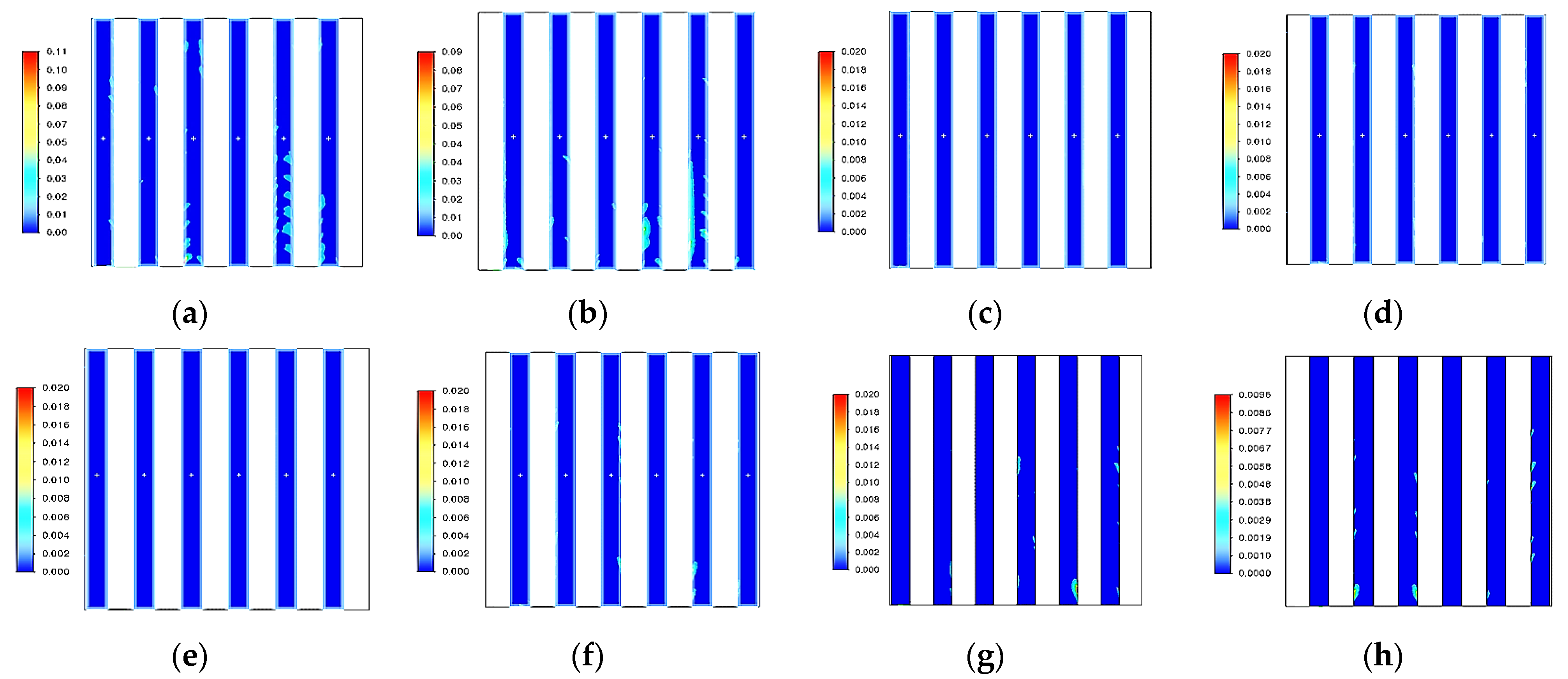
Figure 8.
The regions of erosive wear rates We, mm/year for different rows of elements in the separator with arc-shaped elements at particle diameter dp = 160 µm (frontal view, as seen from the inlet). (a) row 1. (b) row 2. (c) row 3. (d) row 4. (e) row 5. (f) row 6. (g) row 7. (h) row 8.
Figure 8.
The regions of erosive wear rates We, mm/year for different rows of elements in the separator with arc-shaped elements at particle diameter dp = 160 µm (frontal view, as seen from the inlet). (a) row 1. (b) row 2. (c) row 3. (d) row 4. (e) row 5. (f) row 6. (g) row 7. (h) row 8.

Figure 9.
The erosive wear rate We, mm/year as a function of particle diameter for different devices: (1) the cyclone and (2) the separator with arc-shaped elements.
Figure 9.
The erosive wear rate We, mm/year as a function of particle diameter for different devices: (1) the cyclone and (2) the separator with arc-shaped elements.

Table 1.
Mass flow rate of catalyst particles.
| Catalyst Particles, µm | Mass Flow Rate, kg/s |
|---|---|
| 20 | 0.00818040 |
| 25 | 0.03599376 |
| 40 | 0.03926592 |
| 60 | 0.02977666 |
| 100 | 0.03010387 |
| 160 | 0.00654432 |
Table 2.
The maximum annual erosive wear rate of the rows of elements in the separator with arc-shaped elements (mm/year).
Table 2.
The maximum annual erosive wear rate of the rows of elements in the separator with arc-shaped elements (mm/year).
| Row | 1 | 2 | 3 | 4 | 5 | 6 | 7 | 8 | |
|---|---|---|---|---|---|---|---|---|---|
| We, mm/Year | |||||||||
| dp, µm | 20 | 0.09 | 0.07 | 0.016 | 0.015 | 0.017 | 0.02 | 0.018 | 0.0096 |
| 25 | 0.08 | 0.13 | 0.06 | 0.03 | 0.019 | 0.03 | 0.018 | 0.015 | |
| 40 | 0.14 | 0.62 | 0.08 | 0.008 | 0.025 | 0.041 | 0.002 | 0.002 | |
| 60 | 0.18 | 1.47 | 0.11 | 0.009 | 0.041 | 0.052 | 0.001 | ≈0 | |
| 100 | 0.47 | 1.92 | 0.23 | 0.02 | 0.091 | 0.089 | 0.003 | 0.003 | |
| 160 | 0.67 | 2.31 | 0.42 | 0.04 | 0.099 | 0.097 | 0.003 | 0.001 | |
Disclaimer/Publisher’s Note: The statements, opinions and data contained in all publications are solely those of the individual author(s) and contributor(s) and not of MDPI and/or the editor(s). MDPI and/or the editor(s) disclaim responsibility for any injury to people or property resulting from any ideas, methods, instructions or products referred to in the content. |
© 2023 by the authors. Licensee MDPI, Basel, Switzerland. This article is an open access article distributed under the terms and conditions of the Creative Commons Attribution (CC BY) license (https://creativecommons.org/licenses/by/4.0/).
Share and Cite
MDPI and ACS Style
Salakhova, E.I.; Zinurov, V.E.; Dmitriev, A.V.; Salakhov, I.I. Modeling of Erosion in a Cyclone and a Novel Separator with Arc-Shaped Elements. Processes 2023, 11, 156. https://doi.org/10.3390/pr11010156
AMA Style
Salakhova EI, Zinurov VE, Dmitriev AV, Salakhov II. Modeling of Erosion in a Cyclone and a Novel Separator with Arc-Shaped Elements. Processes. 2023; 11(1):156. https://doi.org/10.3390/pr11010156
Chicago/Turabian StyleSalakhova, Elmira I., Vadim E. Zinurov, Andrey V. Dmitriev, and Ilshat I. Salakhov. 2023. "Modeling of Erosion in a Cyclone and a Novel Separator with Arc-Shaped Elements" Processes 11, no. 1: 156. https://doi.org/10.3390/pr11010156
Note that from the first issue of 2016, this journal uses article numbers instead of page numbers. See further details here.