

Process Effluent Recycling in the Supercritical Water Gasification of Dry Biomass


Institute of Catalysis Research and Technology (IKFT), Karlsruhe Institute of Technology (KIT), 76344 Eggenstein-Leopoldshafen, Germany
*
Author to whom correspondence should be addressed.
Processes 2023, 11(3), 797; https://doi.org/10.3390/pr11030797
Submission received: 20 February 2023
/
Revised: 4 March 2023
/
Accepted: 6 March 2023
/
Published: 7 March 2023
(This article belongs to the Special Issue Advances in Sub-/Supercritical Water Processes)
Abstract
:The influence of process water recycling during the Supercritical Water Gasification (SCWG) of dry biomasses was investigated. Dry biomass has to be diluted with water to a dry matter content of approximately 10 wt.% to gasify it in the process of supercritical water gasification. The treatment of wastewater in the SCWG process is cost intensive due to organic contaminants; therefore, the recycling of the process effluent is attractive. Salt separation is needed to avoid accumulation of salts in the effluents, since salts enhance corrosion rates and might cause blocking of the flow when the effluent is recycled. The grass Reed Canary Grass and grapevines were gasified. The recycling of the process effluent did not influence the composition of the product gas. In both cases the carbon efficiency decreased by 4% when wastewater was used to dilute the biomass. An increase in organic carbon and potassium in the reactor effluent was observed after gasification of the biomass with recycled process effluent. The addition of potassium hydroxide to the feed as a homogenous catalyst needs to be closely monitored and adjusted according to the potassium content of the reactor effluent. Insufficient salt separation proved to be an issue regarding formation of solid deposits in the reaction system.
1. Introduction
Supercritical water gasification uses water as a reaction medium to effectively convert biomass into gaseous products. The temperatures and pressures are above the critical point of water (T > 374 °C, p > 22.1 MPa) so that the water is in its supercritical state [1]. Due to the special properties of supercritical water, it is very well miscible with the organic feedstock, which makes fast and homogeneous reactions possible [2].
A particular advantage of SCWG is that the feedstock does not need to be dried [3,4]. Thus, wet organic waste products with high moisture content, such as sewage sludge and animal manure, can be converted in addition to wet biomass, such as microalgae and lignocellulosic [4,5,6]. The composition of the produced gas and the gasification efficiency of SCWG depend on the process parameters, such as temperature, pressure, and biomass concentration in the feed [4,7,8,9]. The organic molecules are hydrolyzed and further decomposed to gases (Equations (1) and (2)) [3,10].
Subsequently, the water gas shift reaction (Equation (3)) and methanation reactions (Equations (4) and (5)) take place [10,11,12].
SCWG produces a gas mixture consisting mainly of H2, CH4, and CO2. C2 and C3 compounds and CO are contained in small proportions [13,14,15,16]. SCWG thus represents a process by which hydrogen can be obtained from biomass. The demand for hydrogen as a clean fuel in the context of the energy transition to renewable energies is high. Another advantage of SCWG is that the gas produced is already compressed; therefore, no further compression is required for subsequent syntheses or storage of the gas [16,17,18].
The application of SCWG on dry biomass is contradictory to the usual application of the SCWG technology, pyrolysis and conventional gasification are generally more appropriate; however, there are scenarios in which the SCWG technology is suitable, e.g., for decentralized processing of dry biomass for the production of syngas. In the H2020 EU-Project CERESiS (ContaminatEd land Remediation through Energy crops for Soil improvement to liquid biofuel Strategies), the goal is to produce Fischer–Tropsch fuels from dry biomass. Through SCWG the needed syngas is produced. SCWG is conducted in one process step, whereas a combination of pyrolysis and conventional gasification would combine two separate processes that require separate plants. Additionally, common entrained flow gasifiers require a larger size than 1 MW for operation. SCWG can be operated at smaller scales. This fits in the framework of the H2020 EU-Project CERESiS, where decentralized applications are needed. Within this CERESiS-project SCWG and pyrolysis of dry biomasses are both assessed and compared with each other.
When dry biomass is processed, a high amount of water with low salt content is necessary to dilute the biomass so that the slurry can be pumped [19] and enough water is available for the reaction. Typically, the dry matter content is 5 to 20% in the feed slurry [19,20]. The providing of salt-free water and the purification or disposal of the process effluent is cost-intensive; therefore, recycling of the process effluent is attractive. This is possible due to low concentrations of salts in the reactor effluent [20]. Salts are poorly soluble in supercritical water [21,22,23] and can block the flow and cause corrosion [5,24]. A salt separation implemented in the process can reduce the amount of salts in the reactor effluent [25] and therefore enable the recycling of process water [15]. Dry biomass contains little water and thus most of the effluent can be reused. In the past, the recycling of process effluent was only investigated for wet biomasses (in a small set of experiments at the Karlsruher Institute of Technology [26]) but not for dry biomasses. The schematic process diagram can be seen in Figure 1.
Another possible way to treat the wastewater could be the SCWG of just the wastewater to further reduce the organic content. This was demonstrated by Yan et al. who gasified the liquid effluent obtained via the hydrothermal carbonization of household kitchen waste [27]. Alternatively, aqueous phase reforming can be used to treat waste water that is contaminated with organics [28,29]. In both cases, an additional process is needed to treat the wastewater. This step is omitted when recycling the wastewater to create new feed slurry.
To optimize the process of SCWG of dry biomasses, the influence of process water recycling has to be investigated. In this paper, the process water recycling during the supercritical water gasification of dry biomasses is tested and the effects on the SCWG process are described. Two different biomasses, a grass and a biomass with wooden stems and branches, were used for the experiments.
2. Materials and Methods
2.1. Preparation of Educts
In the first experiments, Reed Canary Grass (lat. Phalaris arundinacea) was used as biomass. The grass was cultivated in Warden Law, England [30] and provided as a dry powder by the University of Strathclyde. The dry matter content of the biomass was 97.4%. To compare it with a woody biomass, the stems and branches of grapevines, provided by the University of Tuscia, were processed. The dry matter content of the grapevines was 95.1%. The grapevines were delivered in about 10 cm long pieces. The composition of the biomasses is given in Table 1.
To create a feed slurry the biomass had to be in form of a powder. The size of the grapevines was reduced by three steps of milling: first in a wood chipper (GE 260, Viking GmbH, Langkampfen, Austria) to about 2 cm long pieces, then in a mill with 4 mm sieve (Pulverisette 25, Fritsch GmbH, Idar-Oberstein, Germany), and lastly in a mill with 0.2 mm sieve (Pulverisette 14, Fritsch GmbH, Idar-Oberstein, Germany) (see Figure 2). Reed Canary Grass was milled (SM 100, Retsch GmbH, Haan, Germany) by University of Strathclyde and delivered with reduced size (0.25 mm). To adjust the dry mass in the feed slurry to about 8 wt.%, distilled water was added to the biomass. Xanthan was added to the mixture as a thickening agent (0.5 wt.%) to ensure that no phase separation occurred. Xanthan is also gasified under the SCWG conditions. As a homogeneous catalyst, KOH (5000 mg K+/kg feed slurry) was added. KOH enhances the water gas shift reaction and therefore increases the H2-yield [31,32]. It also weakens the intermolecular bonds of the biopolymers due to its alkaline character [33], which increases decomposition of the macromolecules (in feed pH = 9,3). The components were mixed and thermally pretreated at temperatures up to 70 °C for two hours in a mixer (Thermomix TM31, Vorwerk Deutschland Stiftung & Co. KG, Wuppertal, Germany). After cooling, samples of the final slurry were taken to analyze dry matter content and the elemental composition.
2.2. Apparatus
The laboratory tests are carried out in the “Laboratory Plant for Energetic Utilization of Agricultural Materials” (German acronym: LENA) at the Karlsruhe Institute of Technology. LENA is a high-pressure plant that can be operated at temperatures of up to 700 °C and pressures of up to 30 MPa. The pressure is regulated by a TESCOM back-pressure regulator (Emerson Automation Solutions, Selmsdorf, Germany). In the present configuration, the reaction system consists of a preheater, a salt separation, and a gasification reactor (see Figure 3). Thermocouples are mounted on the outside of reactors. D’Jesus showed, in a similar reactor with an inner diameter of 8 mm, that the temperature gradient between the reaction medium and the outside of the reactor wall can be neglected [26]; thus, the outer temperature measurement is representative of the reaction temperature.
The preheater has a length of 750 mm and an inner diameter of 8 mm. It is made of the nickel-based alloy Inconel 625. Due to an installed liner (stainless steel 316), the inner diameter is reduced to 3.2 mm. The preheater is heated from the outside by three electric spiral heaters. Two thermocouples are attached to the outer wall of the pipe for each heater. The supercritical state of water is reached in the preheater. A T-fitting is located downstream of the preheater where salt separation takes place. At T > 374 °C, inorganic compounds drop vertically into the salt concentrate (pipe below the T-piece) due to the low solubility in supercritical water, whereas the biomass slurry is transported to the side to the SCWG reactor. The salt concentrate is ejected from the system into a collection container (atmospheric pressure) by a high-pressure valve that opens the outlet of the pipe below the T-piece for a short time in defined intervals. Within the H2020-project CERESiS, this salt concentrate is further treated to regain purified water.
The gasification reactor is made of the nickel-based alloy Inconel 625 and has a length of 1800 mm and an inner diameter of 8 mm. It is heated from the outside by six electric rod heaters. Nine thermocouples are mounted on the outer wall of the reactor for temperature monitoring. The reaction mixture is converted into gaseous products in the reactor.
Gas meters (Ritter Apparatebau GmbH & Co. KG, Bochum, Germany) and scales (Soehnle Industrial Solutions GmbH, Backnang, Germany) are installed to quantify the products. Liquid and gas samples are taken at regular intervals during the experiment. A steady-state operating condition for the evaluation is defined in which the gas composition and gas production are constant.
The system is brought to pressure by pumping water with an HPLC pump and then heated up. For this purpose, the temperatures are set in the process control system. The day before the actual experiment with biomass, a preliminary test with ethanol solution (5 wt.% ethanol) is started. Gasification of this solution brings the system into a liquid–gas equilibrium. This allows a steady state to be reached more quickly in the main experiment because the dead volumes of the high-pressure–low-temperature part of the plant will be filled with a gas mixture with a similar gas composition as the product gas from the subsequent experiment with biomass. In addition, the system can be checked for leaks before the main experiment. For the main experiment with biomass, the feed slurry is stored in a tank under the same pressure as the experiment. Water is pumped into the tank by a HPLC pump, which pumps the feed slurry indirectly via a piston (see Figure 4).
2.3. Analysis
Gas samples of the product gas are analyzed immediately after sampling in the gas chromatograph 5890 series II plus (Hewlett-Packard GmbH, Waldbronn, Germany) with a fused silica capillary column (Carboxen 1010 PLOT 30 m, SUPELCO). The volume fractions of the gas components H2, CO, CH4, CO2, C2H4, C2H6, C3H8, and C3H6 are determined by a thermal conductivity and a flame ionization detector. Gas samples are taken every 30 min.
During the experiment, small liquid samples are collected out of the effluent streams in regular intervals. The rest of the effluent streams are collected in a glass container (total effluent). In the liquid samples and in the total effluent, the Total Carbon (TC) is determined by combustion and Total Inorganic Carbon (TIC) by acid extraction in a TOC-analyzer (DIMATOC 2100, DIMATEC Analysentechnik GmbH, Essen, Germany). Total Organic Carbon (TOC) is determined by subtracting TIC from TC. The concentration of trace elements (Al, Ca, Cr, Cu, Fe, K, Mg, Mo, Na, Ni, S, Si, and Zn) is determined by ICP-OES (Inductively Coupled Plasma–Optical Emission Spectrometry) in an Agilent 725 spectrometer (Agilent Technologies, Waldbronn, Germany).
Solid samples are analyzed via SEM-EDX (Scanning Electron Microscope–Energy Dispersive X-ray Spectroscopy) in a GeminiSEM 500 (Carl Zeiss AG, Oberkochen, Germany).
2.4. Data Interpretation
The key figures that are necessary for the interpretation of the acquired data (carbon efficiency (CE), conversion of the total organic carbon (TOC-conversion), and residence time ()) are defined in the following section.
The carbon efficiency (CE) describes how much of the carbon in the feed was transferred to the gas phase and is defined as:
: Concentration of component ‘i’ in the gas product (vol%)
: Carbon concentration in the feed (wt.%)
: Number of carbon atoms of component ‘i’ in the gas product
: Feed mass flow (g/h)
: Molar mass of carbon (g/mol)
: Pressure (Pa)
: Universal constant of gases (J/(K × mol))
: Temperature (K)
: Gas flow under ambient conditions (L/h)
The TOC-conversion compares how much TOC ends up in the reactor effluent to the TOC content of the feed slurry. It is defined as:
: Mass flow of reactor effluent (g/h)
: Mass flow of salt concentrate (g/h)
: TOC content of reactor effluent (mg/g)
: TOC content of salt concentrate (mg/g)
During the process a big part of the carbon of the feed slurry is converted into various products such as gases, dissolved inorganic compounds, or organic residue (coke, tar, and soot). The remaining TOC ends up in the wastewater. The TOC-conversion is thus an evaluation criterion of the wastewater quality.
The residence time () is calculated according to Equation (8). To determine the mass content of the reactor, the density under the existing temperature conditions has to be determined. Therefore, the temperature profile of the reactor is divided into sections of length . In these sections, the temperature is assumed to be constant so that the density of the mixture in the section can be determined and the mass content in the reactor can be calculated. For simplicity, the density of the mixture is assumed to be the density of water.
: Inner diameter of the reactor (m)
: Length of section with constant temperature (m)
: Density of water at given temperatures (kg/m3)
At T = 650 °C and p = 28 MPa the density of pure water is = 73.51 kg m−3 (value obtained from the IAPWS-IF97). The density of the SCWG product (a mixture of mainly ) when gasifying 8 wt.% ethanol has a density of = 69.23 kg m−3 (calculated with Aspen HYSYS (Aspen Technology, Bedford, MA, USA)). The reaction product of ethanol is similar to the product when gasifying biomass. Due to the small difference between the densities of water and the reaction product of the gasification of ethanol, only small errors are made when using the density of water to calculate the residence times.
3. Results and Discussion
In total, seven experiments were conducted (see Table 2).
The pressure of the system was 28 MPa, and the temperature of the SCWG reactor was set to 650 °C. The flow rate was set to 700 g h−1. The duration of the experiment was limited by the available amount of feed slurry and therefore varies between the experiments. TPreheater,max describes the maximum temperature that was set in the preheater. Except for experiment 1, the maximum temperature of the preheater was 500 °C. Afterwards, salts are separated with the help of a high-pressure valve that opens in certain intervals (see Table 2 for the chosen intervals) for a very short time (20 ms). In experiments 1 and 3, the interval was extended. Both experiments (1 and 3) ended prematurely due to formation of solids in the SCWG reactor. For that reason, the other experiments were conducted with an interval of 120 s.
3.1. Gasification of Reed Canary Grass
To investigate the influence of the recycling of the reactor effluent gasification, experiments with the grass Reed Canary Grass were conducted (see Table 3). At first, Reed Canary Grass was mixed with distilled water (as described in 2.1) and gasified (experiment 2). The TOC content in the feed slurry was 36,115 mg kg−1. The reactor effluent of experiment 2 was then gasified under the same conditions (experiment 4). The reactor effluent had some inhomogeneities (oily substances) on its surface that could not be detected during the TOC measurement. These oily substances were also recycled and gasified. Due to the inaccuracies in the TOC-measurement, CE and the TOC-conversion might deviate in experiment 4. Due to the low organic carbon content of the effluent, a high gasification efficiency could be reached. As the proportion of organic components decreases, the relative excess of water increases, which results in an increased conversion efficiency [34]. The mixing of organic components with supercritical water is favored by a small amount of organic matter. This leads to better splitting of organic components towards gases [35]. Nanda et al. and D’Jesus observed an increase in gasification efficiency with decreasing organic content [26,36]. A lower organic content also results in a higher hydrogen yield [34]. This has been experimentally confirmed by Lu et al. and Nanda et al. [36,37]. The H2 content in the product gas of the gasified reactor effluent is significantly higher (about 46%) than in the product gas of gasification experiments with biomass (about 31%) (see Figure 5). The high CE and the high H2 content indicate that the reactor effluent can be efficiently gasified and could be used for creating new feed slurries.
Two further experiments (experiment 1 and 3) were conducted under similar conditions as experiment 2 to produce additional reactor effluent. The TOC content of the reactor effluents was similar to experiment 2 (see Table 3). The dry biomass was then mixed with the reactor effluents (instead of distilled water) to create a feed slurry with recycled process water (experiment 5).
The TOC content of the feed slurry with recycled reactor effluent was 42,044 mg kg−1. The experiments show that the recycling of process water does not influence the gas composition of the product gas. In both experiments, the content of H2 is 31%, CO2 is 48%, and CH4 is 16%. The carbon efficiency decreases slightly by about 4% from 59.1 to 55.3% when the effluent is recycled (as shown in Figure 6), which is most probably due to the higher TOC content of the feed.
In general, CE is low under the selected process conditions. Due to high flow rates (700 g h−1), the residence time is short, which affects CE negatively. Gasification rates increase with increasing residence time due to further cracking of biomass molecules. This has been demonstrated experimentally in many studies [26,37,38]. In the conducted experiments, the residence time is 57 s in the section of the SCWG reactor with temperatures higher than 600 °C. Earlier work at the Karlsruher Institute of Technology with corn silage (5 wt.%) in a similar lab plant showed comparable CEs in this range of residence times (τ = 50 s; CE = 60%) [39].
The TOC-conversion is about 0.85 in both experiments, but the reactor effluent of the experiment with recycled process water shows a higher TOC content than the reactor effluent of the experiment with distilled water due to the higher TOC content in the feed slurry. As shown in Table 4, the content of all detected organic compounds rises when the effluent is recycled, especially the concentration of phenols. Regarding SCWG, phenols are relatively inert [19] and thus might accumulate when recycling the effluent more often. Further investigation on rising TOC content is needed in order to determine how often the reactor effluent can be recycled without excessive enrichment of TOC in the effluent.
To avoid corrosion and solid deposits, the content of other elements, especially salts and metals, has also to be monitored. As shown in Table 5, the concentration of calcium, phosphorus, zinc, aluminum, and magnesium is approximately the same in the reactor effluent after recycling.
The concentrations of sodium, sulfur, and silicon rise when the reactor effluent is recycled but remain at a low level. The most significant change can be seen with potassium. The concentration of potassium rises from 2180 to 3850 µg mL−1 when the reactor effluent is reused. The implemented salt separation does not separate the salt components efficiently (detailed description in Section 3.3) but limits the accumulation of salt building elements and metals in the reactor effluent.
Most of the experiments were only conducted once due to limited time and resources and the high effort it takes to prepare and conduct the experiments. One experiment was repeated (experiment 2 and 3) to produce additional reactor effluent. In these two experiments the carbon efficiency deviated only 1.4%. A possible source of error in TOC measurement and in CE are the inhomogeneities in the reactor effluent, which contains a small amount of an oily phase that is too small to be separated (as stated above).
3.2. Gasification of Grapevines
In a second set of experiments grapevines were studied under the same conditions as Reed Canary Grass. At first, the milled grapevines were mixed with distilled water (as described in Section 2.1) to create a feed slurry with about 8% dry mass and then gasified (experiment 6). The reactor effluent of this experiment was then used to create the feed slurry for the second experiment with recycled process water (experiment 7). KOH and xanthan were also added. The TOC content of the feed slurry with distilled water was 35,120 mg kg−1 and with reactor effluent was 41,876 mg kg−1. The experiments show that the gas composition is not influenced by the reuse of the process effluent. The yield of the different compounds varies about ±1% (see Figure 7). In both experiments the mean content of H2 is 32%, CO2 is 49%, and CH4 is 15%.
Similar to the findings with Reed Canary Grass, the carbon efficiency decreases from 55.2 to 51.8% when the reactor effluent is recycled (see Figure 8). At the same time the TOC content of the reactor effluent rises from 3027 mg kg−1 to 3805 mg kg−1. In Table 6, it is shown that, similar to the gasification of Reed Canary Grass, the content of all detected organic compounds in the effluent increases when the effluent is recycled. The TOC-conversion does not change (TOC-conversion = 86%).
A maximum TOC content of the reactor effluent needs to be defined to avoid too high TOC contents in the feed when the effluent is reused multiple times. It might also be possible to reduce the biomass content in the feed to lower the TOC content and therefore produce process effluent with constant TOC content. This needs to be investigated in further experiments in the future.
In addition to the TOC content, the concentration of various elements (salt building elements and metal contaminants) in the effluent is monitored. When the effluent is recycled, the contents of most contaminants (aluminum, calcium, sodium, sulfur, and zinc) are not affected, as can be seen in Table 7. These elements either get separated in the salt concentrate or form solid deposits and therefore do not accumulate in the reactor effluent. A rise in the concentration of potassium from 2430 to 2840 mg µL−1 can be seen. This could also be observed in the gasification of Reed Canary Grass (see Section 3.1), although the accumulation is not as significant during the gasification of grapevines.
The recycling of reactor effluent when gasifying grapevines shows only minor disadvantages regarding CE and the accumulation of TOC in the effluent. In future experiments, the accumulation of potassium in the effluent can be avoided by not adding KOH to the feed when K+ is already contained in the effluent. The same accounts for the gasification of Reed Canary Grass.
3.3. Separation of Salts
Separation of salts is important during the process of SCWG since salts can form solid deposits, cause blockage of the flow [16,40], and also enhance corrosion rates at T > 500 °C [19,40,41,42]. As described in Section 2.2, the salt separation is realized in the form of a T-fitting where salts are supposed to drop vertically down into the salt concentrate due to low solubility in supercritical water at T > 374 °C and due to gravity. The organic material and water leave the T-fitting upwards in an angle of 45° to the SCWG reactor where the organics are gasified (see Figure 9).
The temperature at this T-fitting was T = 388 ± 3 °C during all experiments and thus slightly supercritical (measurement on the outside of the T-fitting). Above its critical point water acts as an nonpolar solvent [43] in which salts generally dissolve poorly. The change in solubility with rising temperature depends on the kind of salt and therefore influences the ability to separate the salts by precipitation [23]. In binary salt–water-systems, it is distinguished between type 1 and type 2 salts [21,44,45]. Type 1 salts (e.g., K2CO3, NaCl, CaCl2) are soluble in dense supercritical water and only precipitate with further rise in temperature, whereas type 2 salts (e.g., Na2CO3, K2SO4, Na2SO4) are (almost) non-soluble [44,46].
Since the temperature of salt separation was at 388 °C and thus only slightly above the critical point of water, not all salts could be sufficiently removed at the T-fitting. This leads to precipitation of some salts in the SCWG reactor due to the further rising of temperatures. The composition of solid deposits that are collected from the SCWG reactor after the experiments cannot be quantitatively detected. The composition of the samples is very heterogeneous (as shown in Figure 10) and therefore can only be qualitatively described (see Section 3.4).
Relevant salt forming elements in the SCWG process are K, P, S, Cl, Ca, Mg, Na, and Si [47,48,49]. In Figure 11, the distribution of relevant salt building elements in the products of experiment 2 is displayed (distribution of elements is similar in all experiments). Depending on the element, between 10 and 80% of the feed content can be detected in the liquid products of the process. Ca, Mg, Na, S, and Si can only be detected to 20% or less. A total of 80% of K can be detected, 40% in the reactor effluent and 30% in the rinse water (after the experiments the reactors are flushed with water). Only 10% is separated into the salt concentrate. As described in Section 3.1 and Section 3.2, the accumulation of potassium in the effluent can be reduced by reducing the amount of potassium that is added to the feed slurry when creating the feed slurry with recycled process water. The mass deficit of all elements, which is displayed in Figure 11, is very high (except for potassium). Most of it can be assumed to be solid deposits in the reaction system, especially in the SCWG reactor, which can only be partially collected. In case of calcium, magnesium, and phosphorus most of the feed-content is separated either in the salt concentrate or in the form of solid deposits. Thus, these elements do not accumulate in the reactor effluent when it is recycled, as can be seen in Table 5.
Due to the high mass deficit and therefore the high amount of salt deposits that are formed in the reactor, the salt separation conditions and the hardware installed are insufficient under the selected process conditions. Salt separation needs to be optimized to ensure that the precipitating salts are removed before a temperature of approximately 450 °C is reached in the SCWG reactor. The geometry of the salt separation T-fitting might show potential for optimization. A sharper redirection of the flow could result in better salt separation. In future experiments, an inner temperature measurement should also be completed to accurately determine the temperature of salt precipitation. Also, the flow velocity should be optimized.
3.4. Formation of Solid Deposits
Aside from salts that can precipitate and block the flow in continuous SCWG plants, coke and char formation poses an additional process challenge. Due to the dilution of the biomass in supercritical water, the contact rate of the biomass molecules with each other decreases, which inhibits the formation of coke [19]. Therefore, the coke and char formation rate is smaller than in conventional gasification [50] but cannot be completely neglected. Coke and char formation can also cause blockage of the flow and decrease the gasification efficiency [50,51,52]. Two of the conducted experiments had to be stopped prematurely due to blockage of the flow in the SCWG reactor. After the end of these experiments, the reactor was opened and solid deposits were removed using a drill. The same procedure was also applied when the experiment was finished according to plan. In all experiments (except for experiment 4 where only the reactor effluent was gasified), solid deposits were found in the top section of the SCWG reactor (about 300–500 mm from the top) in which a temperature of 500 °C was set. An additional indication of the formation of solid deposits is the poor carbon balance of the experiment in the range of 70 to 80%. The collected samples were dried and analyzed via SEM-EDX.
The composition cannot be analyzed quantitively due to the heterogeneity of the solids (see Figure 10) but can be qualitatively analyzed. Many different structures can be seen by SEM-EDX analysis of the solid sample of experiment 5 (see Figure 12). Part of the solid deposit is made up mainly by carbon (area 3). This is visible in the EDX analysis (see Figure 13). Spherical structures can be seen that are fused together in stacks. Spherical carbon structures are known from hydrothermal processes, especially hydrothermal carbonization (HTC) [53,54,55,56]. The HTC process is used to synthesize spherical carbon structures. According to Sun et al. and Li et al., the formation of the carbon spheres follows the LaMer model [56,57], which mainly consists of two steps: nucleation and growth [58]. Sun et al. investigated the HTC of glucose [56]. It is proposed that glucose polymerizes to form aromatic structures and oligosaccharides. Due to further dehydration of these intermediates, nuclei are formed. These nuclei grow due to diffusion of further organics to the surface of the nuclei [56]. During long reaction times, cross-linking and polymerization of spheres can lead to irregular structures [59]. This effect can also be seen in Figure 12. Multiple spheres are fused together and have formed stacks. The sphere formation from glucose has been studied in autoclaves at T < 200 °C by many authors [56,57,60,61]. Zheng et al. investigated HTC of starch at temperatures of 500 to 600 °C [62]. They also found spherical structures, with some spheres fused together. As outlined, the formation mechanism and carbon structures are well described for the process of HTC. In the process of SCWG, the formation of solid carbon is supposed to be limited [19]. In this work, the solid deposits occurred in the SCWG reactor (T > 500 °C). Since the solid samples cannot be collected during the experiment and quenched down to room temperature, the point in time that these spherical structures are formed cannot be determined. The solids were collected after the lab plant cooled down to room temperature. While cooling down, the temperature range of HTC (typically 160 to 250 °C [13]) is passed. A possible origin for the spherical structures could be the formation under the temperature conditions of HTC.
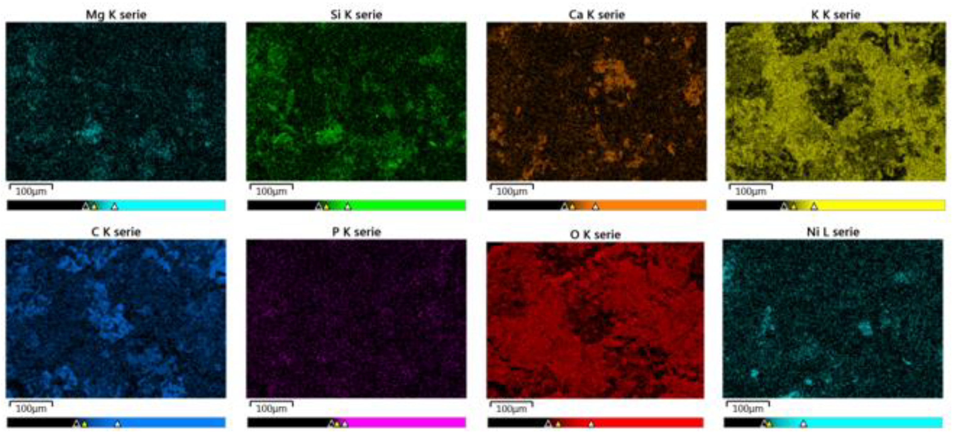
Spherical structures that are stuck together can also be seen in the SEM recordings of the solid deposits of experiment 6 (see Figure 14). The spherical structures are also made up of carbon in this case (see Figure 15) but are larger than in the solid sample of experiment 5.
In area 1 clusters can be seen. These structures consist mainly of silicon in the form of silicon oxide (see Figure 13). Under the conditions of supercritical water gasification, silicon oxide seems to form clusters. Since the solid deposit is mainly made of silicon, the separation of silicates, such as K2(SiO2)n [48], needs to be optimized or a biomass with low silicon content needs to be selected in order to avoid solid deposits and eventually blockage of the flow in the SCWG reactor. Silicon also makes up part of the solid sample of experiment 6, but potassium makes up the biggest part in the form of planar structures (see Figure 14 and Figure 15). As described in Section 3.3, potassium does not become separated by the salt separation sufficiently. This can result in solid deposits in the SCWG reactor as can be seen in experiment 6. Thus, no KOH should be added to the feed when K+ is already contained in the recycled effluent.
Besides the described structures, a planar structure can be seen in area 2. The EDX analysis (see Figure 13) shows that this structure mainly consists of nickel. Therefore, this is a corrosion product that originated from the reactor wall. It is known that alkaline salts cause corrosion under the process conditions present [42,63]. The reactor wall thickness needs to be monitored in order to ensure safe operation of the laboratory plant.
Salt building elements (Si, Mg, Ca, P, and K) can also be detected throughout both samples (see Figure 13 and Figure 15). This indicates that various salt deposits have formed and thus shows that the salt separation prior to the SCWG reactor is insufficient (as described in Section 3.3).
The composition of the solid deposits is complex. Corrosion can be minimized by limiting the amount of the salts in the SCWG reactor. The solid deposits seem to be mainly made up of salts (especially silicon and potassium compounds). This issue needs to be addressed by optimizing the salt separation.
3.5. Estimation of Water Savings through Effluent Recycling
In the experiments, the feed slurry was pumped with 700 g h−1. In the slurry, approximately 640 g h−1 is water. On average, 570 g h−1 of reactor effluent is collected. Due to separation of the salt brine after the preheater, not the whole amount of water in the feed slurry can be collected in the reactor effluent. In a continuous process, the deficit (70 g h−1) needs to be made up with distilled water. This amounts to water savings of 89% when the complete reactor effluent is recycled (see Equation (9)).
To create a feed slurry with 8 wt.% biomass, for 1 kg of dry biomass usually about 11 kg of fresh distilled water is necessary. With the recycling of process water, only about 1.2 kg of fresh water is needed.
4. Conclusions
It was demonstrated that the recycling of the SCWG effluent to produce new feed slurry was possible for dry biomasses. The gasification was successful with a grass, Reed Canary Grass, and a wooden biomass, grapevines. About 89% of the needed water to dilute the feed can be saved by reusing the effluent. There were only minor differences between the gasification of the two biomasses. In both sets of experiments the gas composition was not influenced by the reuse of the effluent. The carbon efficiency decreased only by 4%, probably due to the higher TOC content of the feed. The TOC content and the content of potassium rise in the reactor effluent when the effluent is recycled. In order to minimize accumulation of potassium, the added amount of KOH to the feed needs to be reduced. The TOC content needs to be monitored to define the maximum recycling cycles. Continuous experiments with multiple recycling cycles should be conducted in the future to verify the findings of this study and to find the limitations of the recycling. The salt separation that was installed was insufficient under the selected conditions. This did not influence the recycling of the process effluent since most salts built solid deposits in the reaction system and therefore did not accumulate in the effluent.
Author Contributions
Conceptualization, J.D. and N.B.; methodology, N.B.; validation, J.D., N.B. and J.S.; formal analysis, J.D.; investigation, J.D.; resources, N.B.; data curation, J.D.; writing—original draft preparation, J.D.; writing—review and editing, N.B. and J.S.; visualization, J.D.; supervision, J.S.; funding acquisition, N.B. All authors have read and agreed to the published version of the manuscript.
Funding
This research work was funded by the H2020 EU-Project CERESiS (Grant-Agreement-Nr.: 101006717).
Data Availability Statement
Not applicable.
Acknowledgments
The authors would like to thank E. Hauer for the contributions to the experimental work and K. Weiss, responsible for most of the mechanical work, for his contributions. Special thanks to the University of Strathclyde and the University of Tuscia for providing the biomasses. The authors would like to thank D. Katsourinis and A. Rentizelas for the coordination of the H2020-project CERESiS and R. Lord for commenting on the draft of the paper. We also acknowledge support by the KIT-Publication Fund of the Karlsruhe Institute of Technology.
Conflicts of Interest
The authors declare no conflict of interest.
References
- Kaltschmitt, M.; Hartmann, H.; Hofbauer, H. Energie aus Biomasse, 2nd ed.; Springer: Heidelberg, Germany, 2009; ISBN 978-3-540-85094-6. [Google Scholar]
- Kruse, A.; Dinjus, E. Hot compressed water as reaction medium and reactant properties and synthesis reactions. J. Supercrit. Fluids 2007, 39, 362–380. [Google Scholar] [CrossRef]
- Wang, S.; Xu, D.; Guo, Y. Supercritical Water Processing Technologies for Environment, Energy and Nanomaterial Applications; Springer Nature: Singapore, 2020; ISBN 978-981-13-9325-9. [Google Scholar]
- Boukis, N.; Galla, U.; Müller, H.; Dinjus, E. Biomass Gasification in Supercritical Water. Experimental progress achieved with the VERENA pilot plant. In Proceedings of the 15th European Biomass Conference & Exhibition, Berlin, Germany, 7–11 May 2007. [Google Scholar]
- Yakaboylu, O.; Harnick, J.; Smit, K.G.; Jong, W. Supercritical Water Gasification of Biomass: A Literature and Technology Overview. Energies 2015, 8, 859–894. [Google Scholar] [CrossRef]
- Castello, D.; Kruse, A.; Fiori, L. Supercritical Water Gasification of Glucose/Phenol Mixtures as Model Compounds for Ligno-Cellulosic Biomass. Chem. Eng. Trans. 2014, 37, 193–198. [Google Scholar] [CrossRef]
- Boukis, N.; Diem, V.; Dinjus, E.; Galla, U.; Kruse, A. Biomass Gasification in Supercritical Water. In Proceedings of the 12th European Conference on Biomass for Energy, Industry and Climate Protection, Amsterdam, The Netherlands, 17–21 June 2002. [Google Scholar]
- Demirbas, A. Hydrogen-rich gas from fruit shells via supercritical water extraction. Int. J. Hydrog. Energy 2004, 29, 1237–1243. [Google Scholar] [CrossRef]
- Boukis, N.; Galla, U.; Diem, V.; D’Jesus, P.; Dinjus, E. Hydrogen production from biomass in supercritical water. In Proceedings of the H2-Age: When, Where, Why, Pisa, Italy, 16–19 May 2004. [Google Scholar]
- Resende, F.L.P.; Savage, P.E. Kinetic Model for Noncatalytic Supercritical Water Gasification of Cellulose and Lignin. AIChE J. 2010, 56, 2412–2420. [Google Scholar] [CrossRef]
- Guan, Q.; Wei, C.; Savage, P.E. Kinetic model for supercritical water gasification of algae. Phys. Chem. Chem. Phys. 2012, 14, 3140–3147. [Google Scholar] [CrossRef]
- Waldner, M.H.; Vogel, F. Renewable Production of Methane from Woody Biomass by Catalytic Hydrothermal Gasification. Ind. Eng. Chem. Res. 2005, 44, 4543–4551. [Google Scholar] [CrossRef]
- Kruse, A.; Funke, A.; Titirici, M. Hydrothermal conversion of biomass to fuels and energetic materials. Curr. Opin. Chem. Biol. 2013, 17, 515–521. [Google Scholar] [CrossRef]
- Susanti, R.F.; Veriansyah, B.; Kim, J.-D.; Kim, J.; Lee, Y.-W. Continuous supercritical water gasification of isooctane: A promising reactor design. Int. J. Hydrog. Energy 2010, 35, 1957–1970. [Google Scholar] [CrossRef]
- Boukis, N.; Stoll, I.K. Gasification of Biomass in Supercritical Water, Challenges for the Process Design—Lessons Learned from the Operation Experience of the First Dedicated Pilot Plant. Processes 2021, 9, 455. [Google Scholar] [CrossRef]
- Boukis, N.; Galla, U.; D’Jesús, P.; Müller, H.; Dinjus, E. Gasification of wet biomass in supercritical water. Results of pilot plant experiments. In Proceedings of the 14th European Biomass Conference for Energy, Industry and Climate Protection, Paris, France, 17–21 October 2005. [Google Scholar]
- Gadhe, J.B.; Gupta, R.B. Hydrogen Production by Methanol Reforming in Supercritical Water: Suppression of Methane Formation. Ind. Eng. Chem. Res. 2005, 44, 4577–4585. [Google Scholar] [CrossRef]
- Savage, P.E. A perspective on catalysis in sub- and supercritical water. J. Supercrit. Fluids 2009, 47, 407–414. [Google Scholar] [CrossRef]
- Kruse, A. Supercritical water gasification. Biofuels Bioprod. Bioref. 2008, 2, 415–437. [Google Scholar] [CrossRef]
- Boukis, N.; Galla, U. Verfahren zur hydrothermalen Vergasung von Biomasse in überkritischem Wasser. Forschungszentrum Karlsruhe GmbH, 76133 Karlsruhe, Germany. 2006 044 116 B3, 30 April 2008. [Google Scholar]
- Schubert, M.; Regler, J.W.; Vogel, F. Continuous salt precipitation and separation from supercritical water. Part 1: Type 1 salts. J. Supercrit. Fluids 2010, 52, 99–112. [Google Scholar] [CrossRef]
- Castello, D. Supercritical Water Gasification of Biomass. Ph.D. Thesis, University of Trento, Trento, Italy, 2013. [Google Scholar]
- Armellini, F.J. Phase Equilibria and Precipitation Phenomena of Sodium Chloride and Sodium Sulfate in Sub- and Supercritical Water. Ph.D. Thesis, Massachusetts Institute of Technology, Cambridge, MA, USA, 1993. [Google Scholar]
- Kruse, A. Hydrothermal biomass gasification. J. Supercrit. Fluids 2009, 47, 391–399. [Google Scholar] [CrossRef]
- Boukis, N.; Stoll, I.K.; Sauer, J.; Fischer, J.; Kansy, R. Separation of Salts During the Gasification of Spent Grain in Supercritical Water. In Proceedings of the 25th European Biomass Conference and Exhibition, Stockholm, Sweden, 12–15 June 2017. [Google Scholar]
- D’Jesus, P. Die Vergasung von realer Biomasse in überkritischem Wasser: Untersuchung des Einflusses von Prozessvariablen und Edukteigenschaften. Ph.D. Thesis, Universität Karlsruhe, Karlsruhe, Germany, 2007. [Google Scholar]
- Yan, M.; Liu, Y.; Song, Y.; Xu, A.; Zhu, G.; Jiang, J.; Hantoko, D. Comprehensive experimental study on energy conversion of household kitchen waste via integrated hydrothermal carbonization and supercritical water gasification. Energy 2022, 242, 123054. [Google Scholar] [CrossRef]
- Di Fraia, A.; Miliotti, E.; Rizzo, A.M.; Zoppi, G.; Pipitone, G.; Pirone, R.; Rosi, L.; Chiaramonti, D.; Bensaid, S. Coupling hydrothermal liquefaction and aqueous phase reforming for integrated production of biocrude and renewable H2. AIChE J. 2023, 69, e17652. [Google Scholar] [CrossRef]
- Zoppi, G.; Pipitone, G.; Pirone, R.; Bensaid, S. Aqueous phase reforming process for the valorization of wastewater streams: Application to different industrial scenarios. Catal. Today 2022, 387, 224–236. [Google Scholar] [CrossRef]
- Lord, R.A. Reed canarygrass (Phalaris arundinacea) outperforms Miscanthus or willow on marginal soils, brownfield and non-agricultural sites for local, sustainable energy crop production. Biomass Bioenergy 2015, 78, 110–125. [Google Scholar] [CrossRef] [Green Version]
- Sinag, A.; Kruse, A.; Schwarzkopf, V. Key Compounds of the Hydropyrolysis of Glucose in Supercritical Water in the Presence of K2CO3. Ind. Eng. Chem. Res. 2003, 42, 3516–3521. [Google Scholar] [CrossRef]
- Sinag, A.; Kruse, A.; Rathert, J. Influence of the Heating Rate and the Type of Catalyst on the Formation of Key Intermediates and on the Generation of Gases During Hydropyrolysis of Glucose in Supercritical Water in a Batch Reactor. Ind. Eng. Chem. Res. 2004, 43, 502–508. [Google Scholar] [CrossRef]
- Zhu, Z.; Toor, S.S.; Rosendahl, L.A.; Yu, D.; Chen, G. Influence of alkali catalyst on product yield and properties via hydrothermal liquefaction of barley straw. Energy 2015, 80, 284–292. [Google Scholar] [CrossRef]
- Nanda, S.; Gong, M.; Hunter, H.N.; Dalai, A.K.; Gökalp, I.; Kozinski, J.A. An assessment of pinecone gasification in subcritical, near-critical and supercritical water. Fuel Process. Technol. 2017, 168, 84–96. [Google Scholar] [CrossRef]
- Okolie, J.A.; Rana, R.; Nanda, S.; Dalai, A.K.; Kozinski, J.A. Supercritical water gasification of biomass: A state-of- the-art review of process parameters, reaction mechanisms and catalysis. Sustain. Energy Fuels 2019, 3, 578–598. [Google Scholar] [CrossRef]
- Nanda, S.; Reddy, S.N.; Hunter, H.N.; Dalai, A.K.; Kozinski, J.A. Supercritical water gasification of fructose as a model compound for waste fruits and vegetables. J. Supercrit. Fluids 2015, 104, 112–121. [Google Scholar] [CrossRef]
- Lu, Y.; Guo, L.; Zhang, X.; Hao, X.; Yan, Q. Hydrogen production by biomass gasification in supercriticalwater: A parametric study. Int. J. Hydrog. Energy 2006, 31, 822–831. [Google Scholar] [CrossRef]
- Wang, C.; Du, M.; Feng, H.; Jin, H. Experimental investigation on biomass gasification mechanism in supercritical water for poly-generation of hydrogen-rich gas and biochar. Fuel 2022, 319, 123809. [Google Scholar] [CrossRef]
- D’Jesus, P.; Boukis, N.; Kraushaar-Czarnetski, B.; Dinjus, E. Influence of Process Variables on Gasification of Corn Silage in Supercritical Water. Ind. Eng. Chem. Res. 2006, 45, 1622–1630. [Google Scholar] [CrossRef]
- Hodes, M.; Marrone, P.A.; Hong, G.T.; Smith, K.A.; Tester, J.W. Salt precipitation and scale control in supercritical water oxidation—Part A. Fundamentals and research. J. Supercrit. Fluids 2004, 29, 265–288. [Google Scholar] [CrossRef]
- Kritzer, P.; Boukis, N.; Dinjus, E. Factors controlling corrosion in high-temperature aqueous solutions. A contribution to the dissociation and solubility data influencing corrosion processes. J. Supercrit. Fluids 1999, 15, 205–227. [Google Scholar] [CrossRef]
- Boukis, N.; Habicht, W.; Hauer, E.; Weiss, K.; Dinjus, E. Corrosion Behavior of Ni-Base Alloys and Stainless Steels in Supercritical Water Containing Potassium Hydrogen Carbonate. In Proceedings of the EUROCORR 2008: The European Corrosion Congress, Edinburgh, UK, 7 September 2008. [Google Scholar]
- Loppinet-Serani, A.; Aymonier, C.; Cansell, F. Current and Foreseeable Applications of Supercritical Water for Energy and the Environment. ChemSusChem 2008, 1, 486–503. [Google Scholar] [CrossRef]
- Schubert, M. Catalytic hydrothermal gasification of biomass—Salt recovery and continous gasifiaction of glycerol solutions. Ph.D. Thesis, Eidgenössische Technische Hochschule Zürich, Zurich, Switzerland, 2010. [Google Scholar]
- Valyashko, V. Phase behaviour in binary and ternary water-salt systems at high temperatures and pressures. Pure Appl. Chem. 1997, 69, 2271–2280. [Google Scholar] [CrossRef]
- Weingärtner, H.; Franck, E.U. Überkritisches Wasser als Lösungsmittel. Angew. Chem. 2005, 117, 2730–2752. [Google Scholar] [CrossRef]
- Ekpo, U.; Ross, A.B.; Camargo-Valero, M.A.; Williams, P.T. A comparison of product yields and inorganic content in process streams following thermal hydrolysis and hydrothermal processing of microalgae, manure and digestate. Bioresour. Technol. 2016, 200, 951–960. [Google Scholar] [CrossRef]
- Zhao, L.; Zhang, J.; Sheng, C.D.; Wang, K.; Ding, Q.Z. Dissolution Characteristics of Inorganic Elements Existing in Biomass during the Supercritical Water Gasification Process. Energy Sources Part A: Recovery Util. Environ. Eff. 2012, 34, 1893–1900. [Google Scholar] [CrossRef]
- Yanagida, T.; Minowa, T.; Nakamura, A.; Matsumura, Y.; Noda, Y. Behavior of Inorganic Elements in Poultry Manure during Supercritical Water Gasification. J. Jpn. Inst. Energy 2008, 87, 731–736. [Google Scholar] [CrossRef] [Green Version]
- Chuntanapum, A.; Matsumura, Y. Char Formation Mechanism in Supercritical Water Gasification Process: A Study of Model Compounds. Ind. Eng. Chem. Res. 2010, 49, 4055–4062. [Google Scholar] [CrossRef]
- Guo, L.J.; Lu, Y.J.; Zhang, X.M.; Ji, C.M.; Guan, Y.; Pei, A.X. Hydrogen production by biomass gasification in supercritical water: A systematic experimental and analytical study. Catal. Today 2007, 129, 275–286. [Google Scholar] [CrossRef]
- Reddy, S.N.; Nanda, S.; Dalai, A.K.; Kozinski, J.A. Supercritical water gasification of biomass for hydrogen production. Int. J. Hydrog. Energy 2014, 39, 6912–6926. [Google Scholar] [CrossRef]
- Romero-Anaya, A.J.; Ouzzine, M.; Lillo-Rodenas, M.A.; Linares-Solano, A. Spherical carbons: Synthesis, characterization and activation processes. Carbon 2014, 68, 296–307. [Google Scholar] [CrossRef]
- Mwenya, T.; Fan, H.; Dai, H.; Li, M. The Detailed Evolution of Carbon Spheres by Hydrothermal Method. Int. J. Photoenergy 2016, 2016, 9057418. [Google Scholar] [CrossRef] [Green Version]
- Sun, X.; Li, Y. Hollow carbonaceous capsules from glucose solution. J. Colloid Interface Sci 2005, 291, 7–12. [Google Scholar] [CrossRef] [PubMed]
- Sun, X.; Li, Y. Colloidal Carbon Spheres and Their Core/Shell Structures with Noble-Metal Nanoparticles. Angew. Chem. Int. Ed. 2004, 43, 597–601. [Google Scholar] [CrossRef] [PubMed]
- Li, M.; Li, W.; Liu, S. Hydrothermal synthesis, characterization, and KOH activation of carbon spheres from glucose. Carbohydr. Res. 2011, 346, 999–1004. [Google Scholar] [CrossRef]
- LaMer, V.; Dinegar, R.H. Theory, Production and Mechanism of Formation of Monodispersed Hydrosols. J. Am. Chem. Soc. 1950, 72, 4847–4854. [Google Scholar] [CrossRef]
- Chen, S.; Tang, K.; Song, F.; Liu, Z.; Zhang, N.; Lan, S.; Xie, X.; Wu, Z. Porous hard carbon spheres derived from biomass for high-performance sodium/potassium-ion batteries. Nanotechnology 2002, 33, 055401. [Google Scholar] [CrossRef]
- Qi, X.; Lian, Y.; Yan, L.; Smith, R.L., Jr. One-step preparation of carbonaceous solid acid catalysts by hydrothermal carbonization of glucose for cellulose hydrolysis. Catal. Commun. 2014, 57, 50–54. [Google Scholar] [CrossRef]
- Wang, Q.; Li, H.; Chen, L.; Huang, X. Monodispersed hard carbon spherules with uniform nanopores. Carbon 2001, 39, 2211–2214. [Google Scholar] [CrossRef]
- Zheng, M.; Liu, Y.; Xiao, Y.; Zhu, Y.; Guan, Q.; Yuan, D.; Zhang, J. An Easy Catalyst-Free Hydrothermal Method to Prepare Monodisperse Carbon Microspheres on a Large Scale. J. Phys. Chem. C 2009, 113, 8455–8459. [Google Scholar] [CrossRef]
- Boukis, N.; Hauer, E.; Habicht, W. Corrosion Behaviour of Ni-Base Alloys in Supercritical Water Containing Alkali Chlorides. In Proceedings of the EUROCORR 2013: The European Corrosion Congress, Estoril, Portugal, 2 September 2013. [Google Scholar]
Figure 1.
Schematic diagram of the recycling process.

Figure 2.
Different size reduction steps of grapevines (scale in cm).
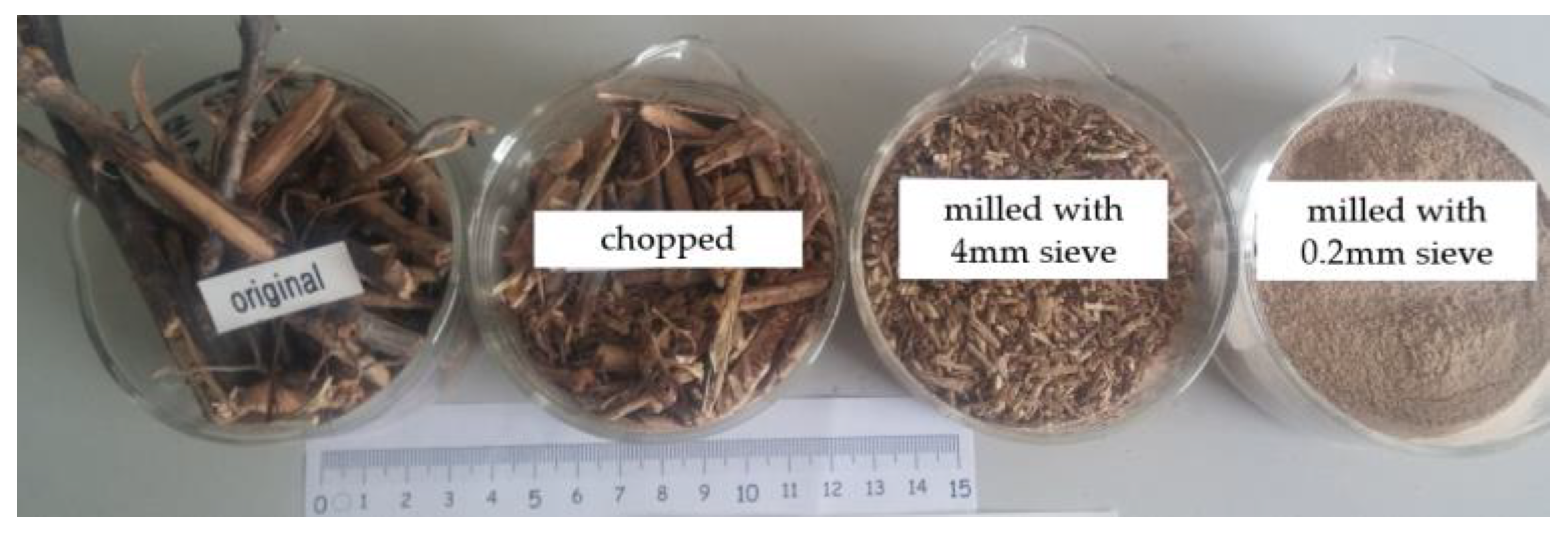
Figure 3.
High-pressure laboratory equipment for supercritical water gasification.
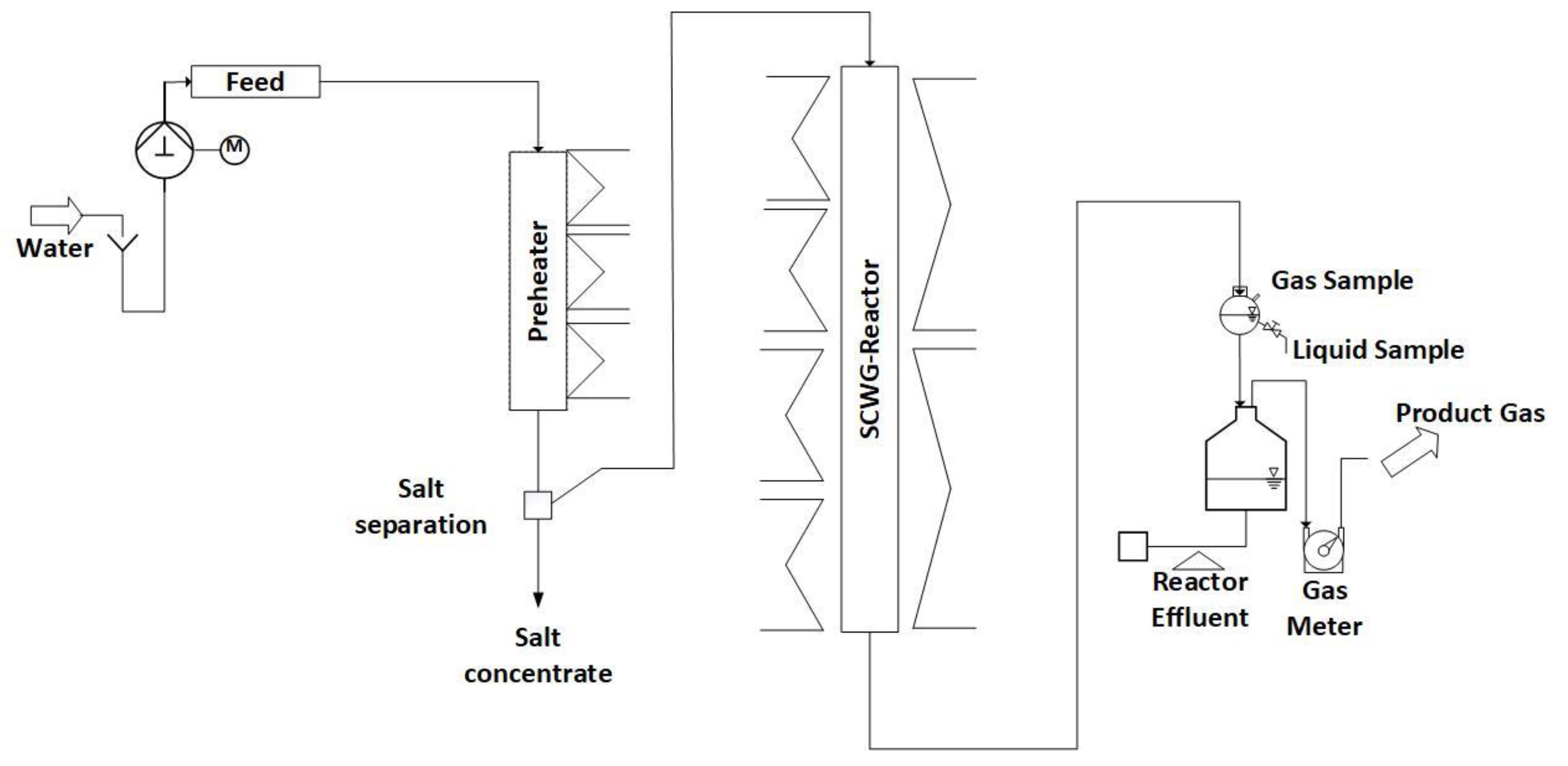
Figure 4.
Pumping system of the LENA lab plant.
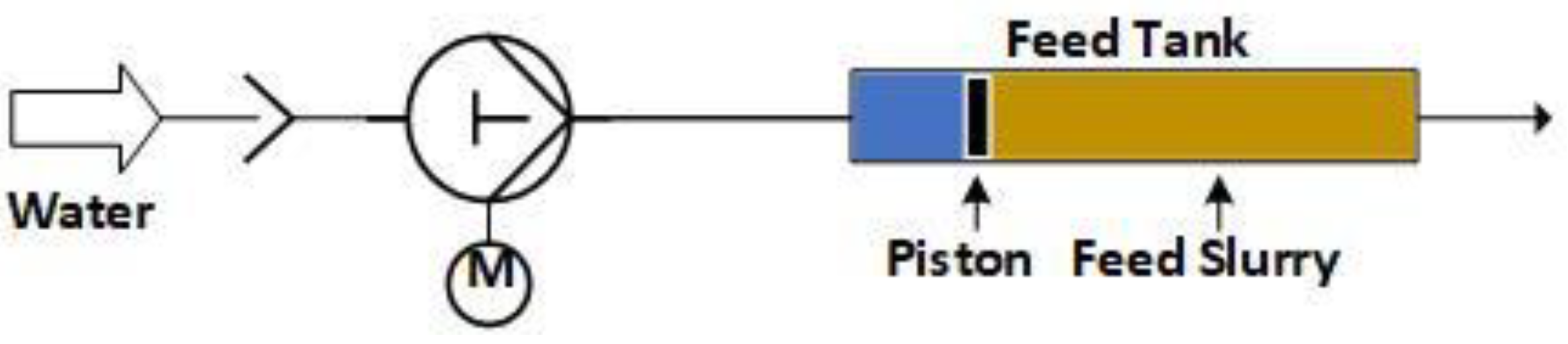
Figure 5.
Gas composition of experiments with Reed Canary Grass for three different feeds.
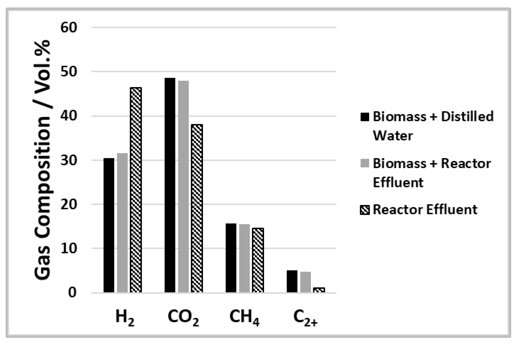
Figure 6.
Carbon efficiency and TOC content of reactor effluent of gasification experiments with Reed Canary Grass for three different feeds.
Figure 6.
Carbon efficiency and TOC content of reactor effluent of gasification experiments with Reed Canary Grass for three different feeds.
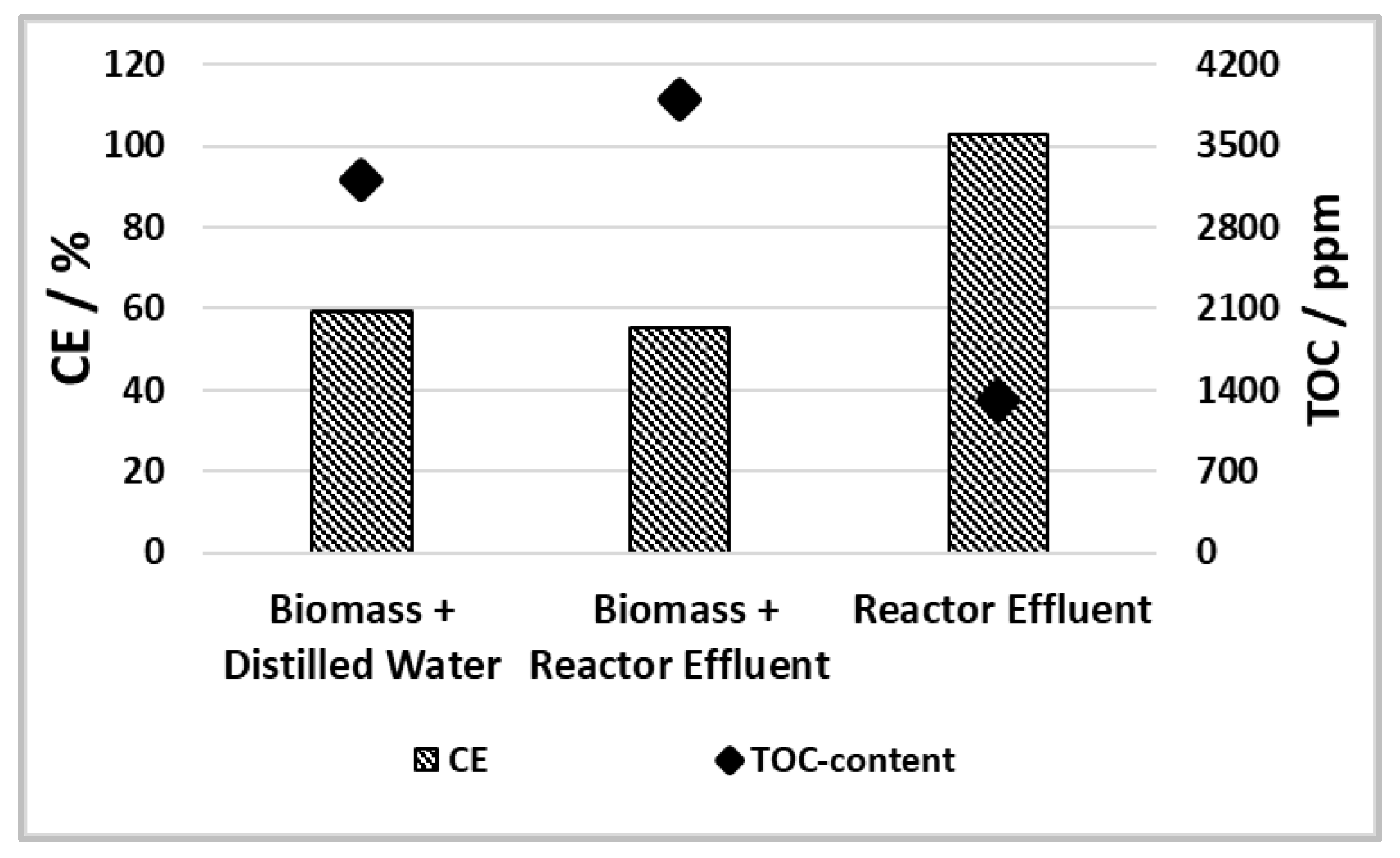
Figure 7.
Gas composition of gasification experiments with grapevines for two different feeds.
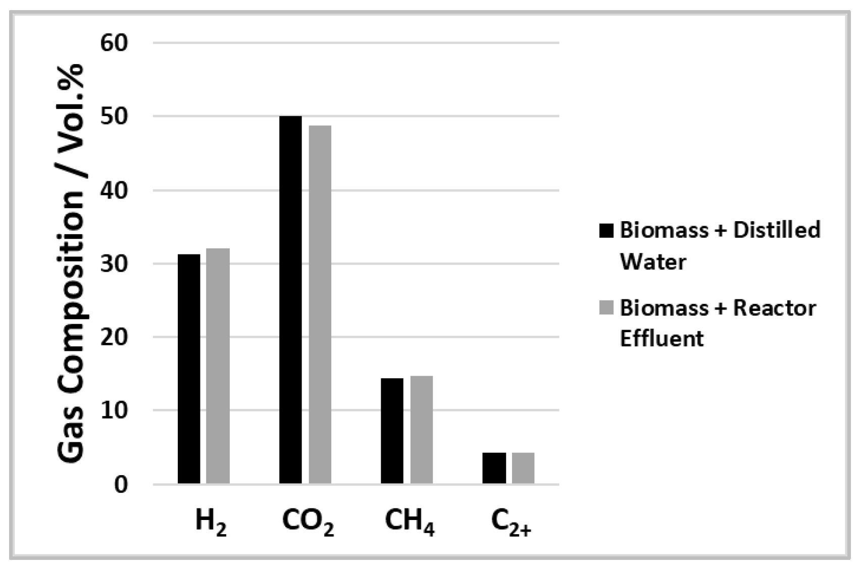
Figure 8.
Carbon efficiency and TOC content of reactor effluent of gasification experiments with grapevines for two different feeds.
Figure 8.
Carbon efficiency and TOC content of reactor effluent of gasification experiments with grapevines for two different feeds.
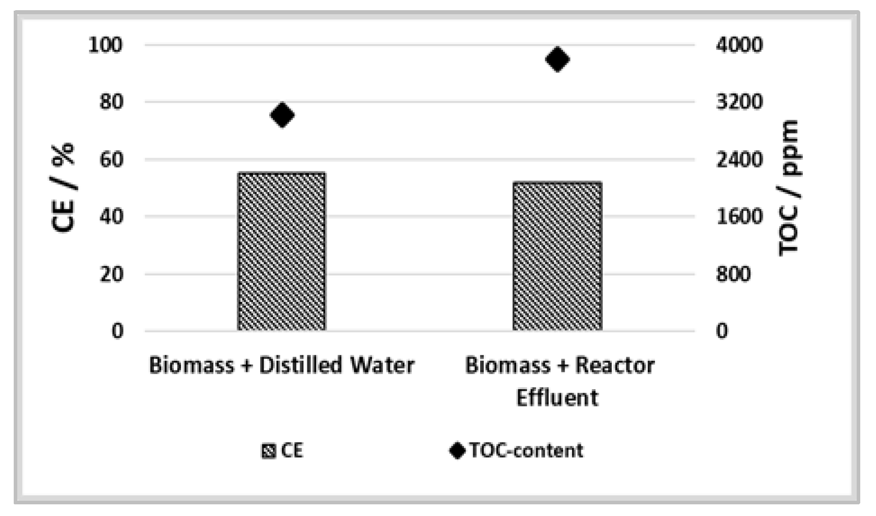
Figure 9.
Design of salt separation in LENA plant for the current experiments.

Figure 10.
Solid sample from SCWG reactor in experiment 5 and experiment 6.

Figure 11.
Distribution of salt building elements in the products of experiment 2 (concentration in feed = 100%).
Figure 11.
Distribution of salt building elements in the products of experiment 2 (concentration in feed = 100%).
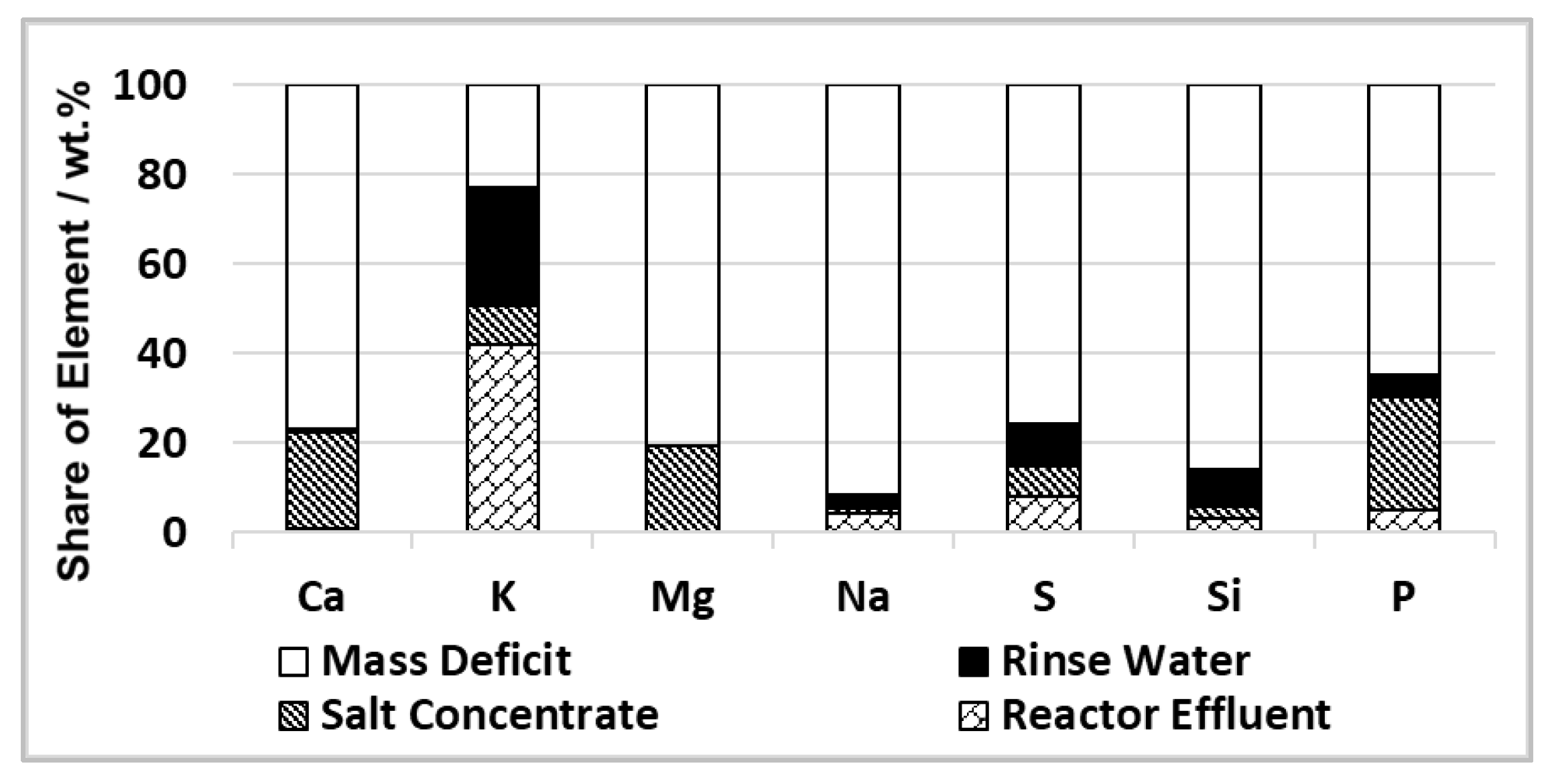
Figure 12.
SEM recordings of solid deposits of experiment 5.
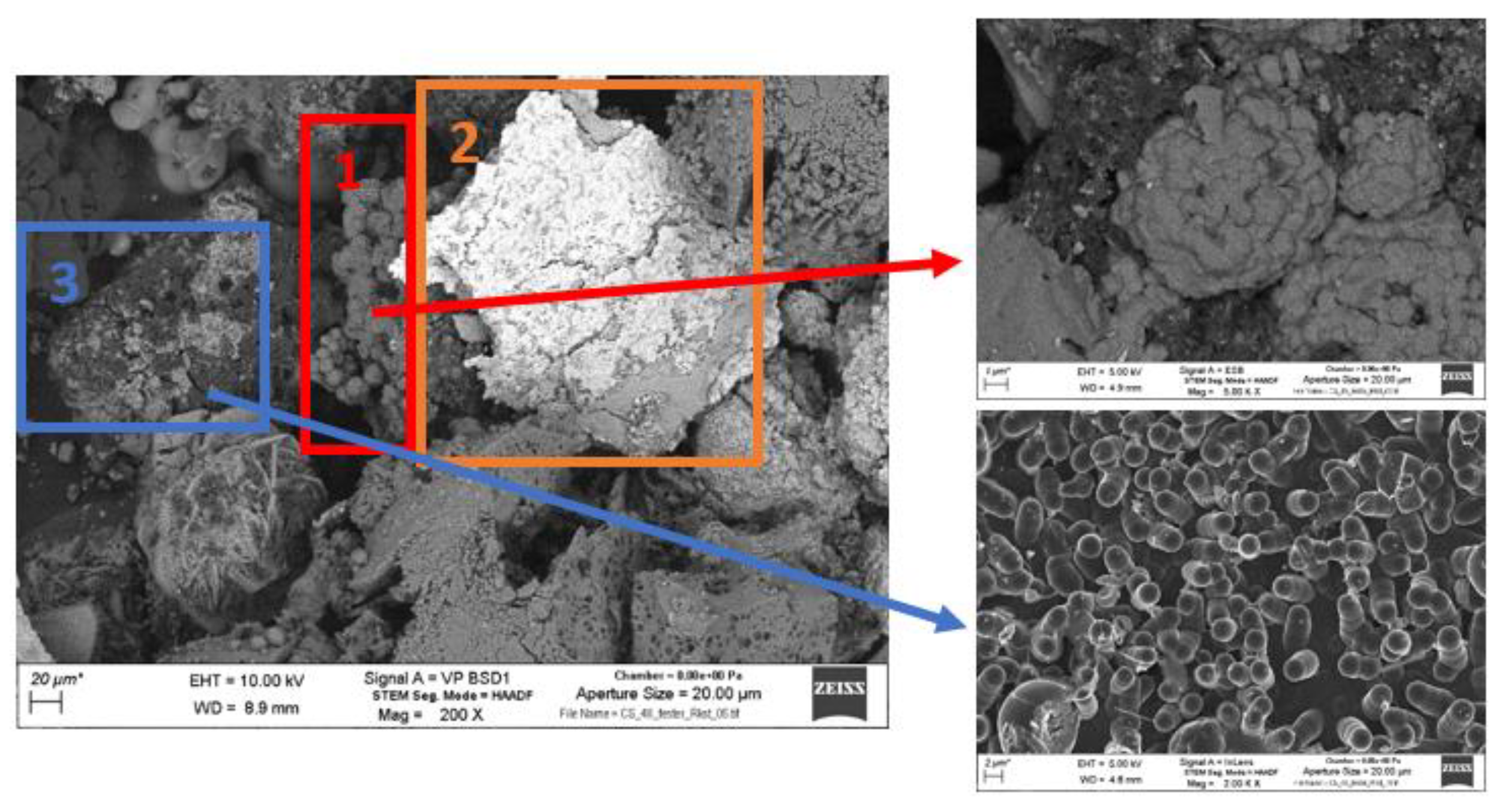
Figure 13.
EDX analysis of solid deposits from experiment 5.
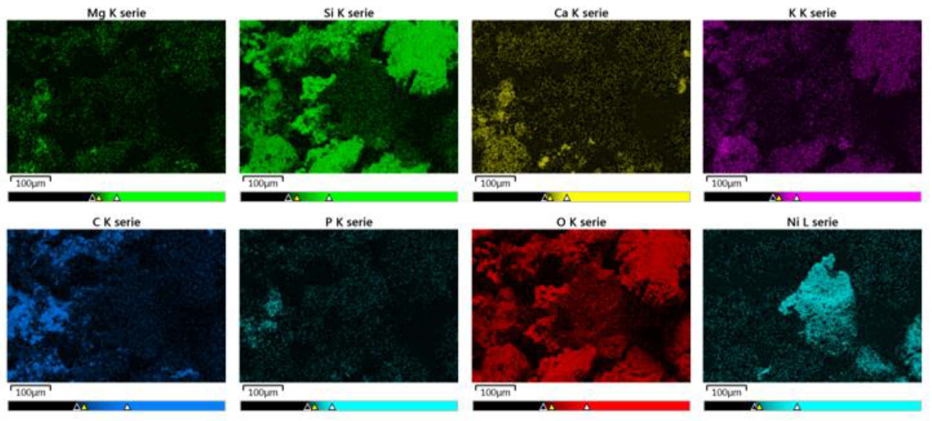
Figure 14.
SEM recordings of solid deposits of experiment 6.

Figure 15.
EDX analysis of solid deposits from experiment 6.

Table 1.
Composition of biomasses in wt.% (dry mass).
| Biomass | C | O | H | N | S |
|---|---|---|---|---|---|
| Reed Canary Grass | 48.9 | 35.9 | 7.46 | <0.3 | 0.09 |
| Grapevines | 47.1 | 42.8 | 4.47 | 1.2 | 0.003 |
Table 2.
Experimental Conditions of SCWG process.
| Experiment Number | Feed | Duration | TPreheater,max | Interval of Salt Separation |
|---|---|---|---|---|
| h | °C | s | ||
| 1 | Reed Canary Grass (8 wt.%) + distilled water | 3.5 * | 460 | 180 |
| 2 | Reed Canary Grass (8 wt.%) + distilled water | 6.5 | 500 | 120 |
| 3 | Reed Canary Grass (8 wt.%) + distilled water | 2.5 * | 500 | 240 |
| 4 | Reactor effluent of 2 | 5.0 | 500 | - |
| 5 | Reed Canary Grass (8 wt.%) + reactor effluent of 1 and 3 | 4.8 | 500 | 120 |
| 6 | Grapevines (8 wt.%) + distilled water | 5.8 | 500 | 120 |
| 7 | Grapevines (8 wt.%) + reactor effluent of 6 | 4.5 | 500 | 120 |
* Premature end of experiment due to formation of solid deposits in the SCWG reactor.
Table 3.
Results of gasification experiments.
| Experiment Number | Feed | CE % | TOC-Conversion % | TOC Content in Effluent mg kg−1 |
|---|---|---|---|---|
| 1 | Reed Canary Grass (8 wt.%) + distilled water | 67.35 | 89.69 | 3765 |
| 2 | Reed Canary Grass (8 wt.%) + distilled water | 59.14 | 83.83 | 3204 |
| 3 | Reed Canary Grass (8 wt.%) + distilled water | 57.73 | 86.85 | 3230 |
| 4 | Reactor effluent of 2 | 102.73 | 59.32 | 1311 |
| 5 | Reed Canary Grass (8 wt.%) + reactor effluent of 1 and 3 | 55.31 | 86.11 | 3902 |
| 6 | Grapevines (8 wt.%) + distilled water | 55.18 | 86.20 | 3027 |
| 7 | Grapevines (8 wt.%) + reactor effluent of 6 | 51.80 | 86.51 | 3805 |
Table 4.
Organics in reactor effluents of the experiments with Reed Canary Grass (in mg L−1).
| Effluent of Experiment | Formic Acid | Acetic Acid | Resorcinol | Phenol |
|---|---|---|---|---|
| 2 | 640 | 57 | 177 | 361 |
| 5 | 742 | 76 | 187 | 618 |
Table 5.
Elemental composition of effluents of experiments with Reed Canary Grass (in µg mL−1).
| Effluent of Experiment | Al | Ca | K | Mg | Na | S | Si | Zn | P |
|---|---|---|---|---|---|---|---|---|---|
| 2 | <2 (0.1) | 2.51 | 2180 | <0.8 (0.1) | 46.1 | 20.6 | 75.5 | <0.2 (0.02) | 6.8 |
| 5 | <2 (0.3) | 2.12 | 3850 | <0.8 | 66.2 | 43.4 | 102 | Not detected | 5.8 |
Table 6.
Organics in reactor effluents of the experiments with grapevines (in mg L−1).
| Effluent of Experiment | Formic Acid | Acetic Acid | Resorcinol | Phenol |
|---|---|---|---|---|
| 6 | 470 | 32 | 178 | 440 |
| 7 | 808 | 121 | 312 | 760 |
Table 7.
Elemental composition of reactor effluents of experiments with grapevines (in µg mL−1).
| Effluent of Experiment | Al | Ca | K | Mg | Na | S | Si | Zn | P |
|---|---|---|---|---|---|---|---|---|---|
| 6 | <2 (0.06) | <2 (1) | 2430 | <0.8 (0.06) | 33.3 | 4.1 | 26 | n.d. | n.d. |
| 7 | <2 (0.3) | 6.06 | 2840 | <0.8 (0.3) | 31.7 | 6.8 | 15.9 | n.d. | <4 (3.2) |
n.d. = not detected.
Disclaimer/Publisher’s Note: The statements, opinions and data contained in all publications are solely those of the individual author(s) and contributor(s) and not of MDPI and/or the editor(s). MDPI and/or the editor(s) disclaim responsibility for any injury to people or property resulting from any ideas, methods, instructions or products referred to in the content. |
© 2023 by the authors. Licensee MDPI, Basel, Switzerland. This article is an open access article distributed under the terms and conditions of the Creative Commons Attribution (CC BY) license (https://creativecommons.org/licenses/by/4.0/).
Share and Cite
MDPI and ACS Style
Dutzi, J.; Boukis, N.; Sauer, J. Process Effluent Recycling in the Supercritical Water Gasification of Dry Biomass. Processes 2023, 11, 797. https://doi.org/10.3390/pr11030797
AMA Style
Dutzi J, Boukis N, Sauer J. Process Effluent Recycling in the Supercritical Water Gasification of Dry Biomass. Processes. 2023; 11(3):797. https://doi.org/10.3390/pr11030797
Chicago/Turabian StyleDutzi, Julian, Nikolaos Boukis, and Jörg Sauer. 2023. "Process Effluent Recycling in the Supercritical Water Gasification of Dry Biomass" Processes 11, no. 3: 797. https://doi.org/10.3390/pr11030797
Note that from the first issue of 2016, this journal uses article numbers instead of page numbers. See further details here.