
Review on Energy Conservation of Construction Machinery for Pumping Concrete
1
School of Mechanical Engineering, Guizhou University, Guiyang 550025, China
2
College of Civil Engineering, Guizhou University, Guiyang 550025, China
*
Author to whom correspondence should be addressed.
Processes 2023, 11(3), 842; https://doi.org/10.3390/pr11030842
Submission received: 24 January 2023
/
Revised: 3 March 2023
/
Accepted: 9 March 2023
/
Published: 11 March 2023
(This article belongs to the Special Issue Automation Control Systems & Process Control for Industry 4.0)
Abstract
:The excessive consumption of fossil fuel, energy shortage and global warming along with environmental deterioration have increasingly become a global issue. In order to deal with the energy crisis, energy conservation has been developed and applied in vehicles and construction machineries, i.e., excavators, loaders and forklifts. Due to the shortcoming of low efficiency, high-energy consumption and bad exhaust, the energy conservation of construction machinery for pumping concrete is necessary and urgent. This paper aims to carry out a review on energy conservation of construction machinery for pumping concrete. The research methodology comprises a quantitative analysis method and literature investigation method. First, the structure and working principle of construction machinery for pumping concrete are expounded, and energy consumption ways of construction machinery for pumping concrete are analyzed. Then, research developments in the energy conservation of construction machinery for pumping concrete are summarized. Finally, challenges with the energy conservation of construction machinery for pumping concrete are presented.
1. Introduction
With the rapid development of the global economy, governments have been focusing on the construction of infrastructures such as high-rise buildings, water power stations and long-span bridges where fresh concrete are required to be transported quickly. Reducing time, as the mark of differentiating modern and conventional construction modes, is a feasible way to realize rapid construction [1]. In order to satisfy the increasing requirement of rapid construction, pumping concrete known as a common technique for transporting fresh concrete has been extensively used in various construction sites worldwide. Pumping concrete can make the construction of many infrastructures feasible, i.e., high-rise buildings and long-span bridges, within a very short time period [2,3,4,5,6,7,8]. It not only can significantly improve the work efficiency and shorten the construction process duration, but also can notably lighten labor intensity and ensure good construction quality [9,10].
In recent years, the excessive consumption of fossil fuel, energy shortage and global warming as well as environmental deterioration have increasingly become a global issue. In order to deal with the energy crisis, energy conservation has been developed and applied in vehicles and construction machineries, i.e., excavators [11,12,13,14], forklifts [15,16,17], cranes [18,19,20,21,22] and loaders [23,24,25,26]. Concrete pumps, a kind of construction machinery for pumping concrete, have been widely used in many fields such as high-rise buildings, water power stations and long-span bridges. Traditional concrete pump has some disadvantages including low efficiency, high-energy consumption and bad exhaust. The application of energy conservation to concrete pumps will improve engine efficiency, reduce energy consumption and promote engine exhaust; thus, carrying out research on energy conservation for concrete pumps is necessary and urgent.
With the application of automatic control technology, visualization technology, fault diagnosis and monitoring technology, etc., the concrete pump has become the high knowledge-intensive and high value-added product. Many concrete pump manufactures and research institutions have been carrying out a number of studies on concrete pumps. Now, they are aware of the importance and urgency of energy conservation for concrete pumps and have put much effort into this. To date, in the literature, many contributions toward energy conservation for concrete pumps can be found.
This paper aims to carry out a review on the energy conservation of construction machinery for pumping concrete. The research methodology of this paper comprises a quantitative analysis method and literature investigation method. The remainder of this paper is organized as follows: In Section 2, the methodology of this study is described. In Section 3, the structure and working principle of concrete pumps are expounded, and energy consumption ways for concrete pumps are analyzed. In Section 4, recent research developments in the energy conservation of concrete pumps are summarized. The challenges with energy conservation for concrete pumps are presented in Section 5. Finally, conclusions are drawn in Section 6.
2. Methodology
The methodology for this study includes a quantitative analysis method and literature investigation method. Figure 1 shows the overview of the basic research process for this study, which includes 6 steps as follows.
Step 1: Purpose
First, it is clear that the purpose of this study is to comprehensively and deeply understand the issue of energy conservation for concrete pumps.
Step 2: Objectives
At present, there are three types of concrete pumps widely used in the world, namely trailer concrete pumps, transported concrete pumps and truck-mounted concrete pumps. Therefore, this study selected three types of concrete pumps as the research objectives.
Step 3: Data collection
Currently, there are numerous documents related to concrete pumps. Effective collection of documents required for this study ensured the integrity and credibility of this study. The research literature was retrieved from academic databases including WOS, Google Scholar and CNKI using the search strategy of (“concrete pump” AND “energy conservation” OR “energy saving”).
Step 4: Analysis of energy consumption ways for concrete pumps
The three types of concrete pumps are composed of multiple components, and there is a conversion between different types of energy. There is an energy loss in the process of energy conversion and transmission. This paper describes the basic structure and working principle of three types of concrete pumps, and analyzes the energy consumption ways for three types of concrete pumps.
Step 5: Developments in energy conservation of concrete pumps
To date, researchers and manufacturers of concrete pumps have developed a variety of energy conservation methods and technologies for concrete pumps, each of which has its own characteristics. This paper analyzes the research developments in the energy conservation of concrete pumps.
Step 6: Challenges with energy conservation of concrete pumps
Due to the limitations of relevant technologies, there are still some challenges with the energy saving of concrete pumps. Moreover, this paper discusses the challenges with the energy conservation of concrete pumps.
3. Analysis of Energy Consumption Ways for Concrete Pumps
3.1. Structure and Working Principle
There are three types of concrete pumps, namely trailer concrete pumps, transported concrete pumps and truck-mounted concrete pumps, as shown in Figure 2.
As shown in Figure 3, trailer concrete pumps mainly consist of an engine, a hydraulic pump, control valves, a main system and auxiliary system. The main system including a pumping system, oscillating system and agitating system is used to realize pumping concrete. The auxiliary system including outrigger system, cleaning system, lubrication system and cooling system is used for the maintenance of the concrete pump.
Mechanical power offered by the engine is inputted into the hydraulic pump, and then the hydraulic pump rotates and sucks oil from the tank, consequently discharging oil into the oil pipe. By this mechanism, mechanical power provided by the engine is transferred to hydraulic power. The pressure oil from hydraulic pump flows through control valves into cylinders or hydraulic motors. Cylinders or hydraulic motors are driven by the pressure oil. By this mechanism, the hydraulic power in the cylinders or hydraulic motors is converted to mechanical power; cylinders or hydraulic motors carry out corresponding pumping work, oscillating work, agitating work or cooling work, etc.
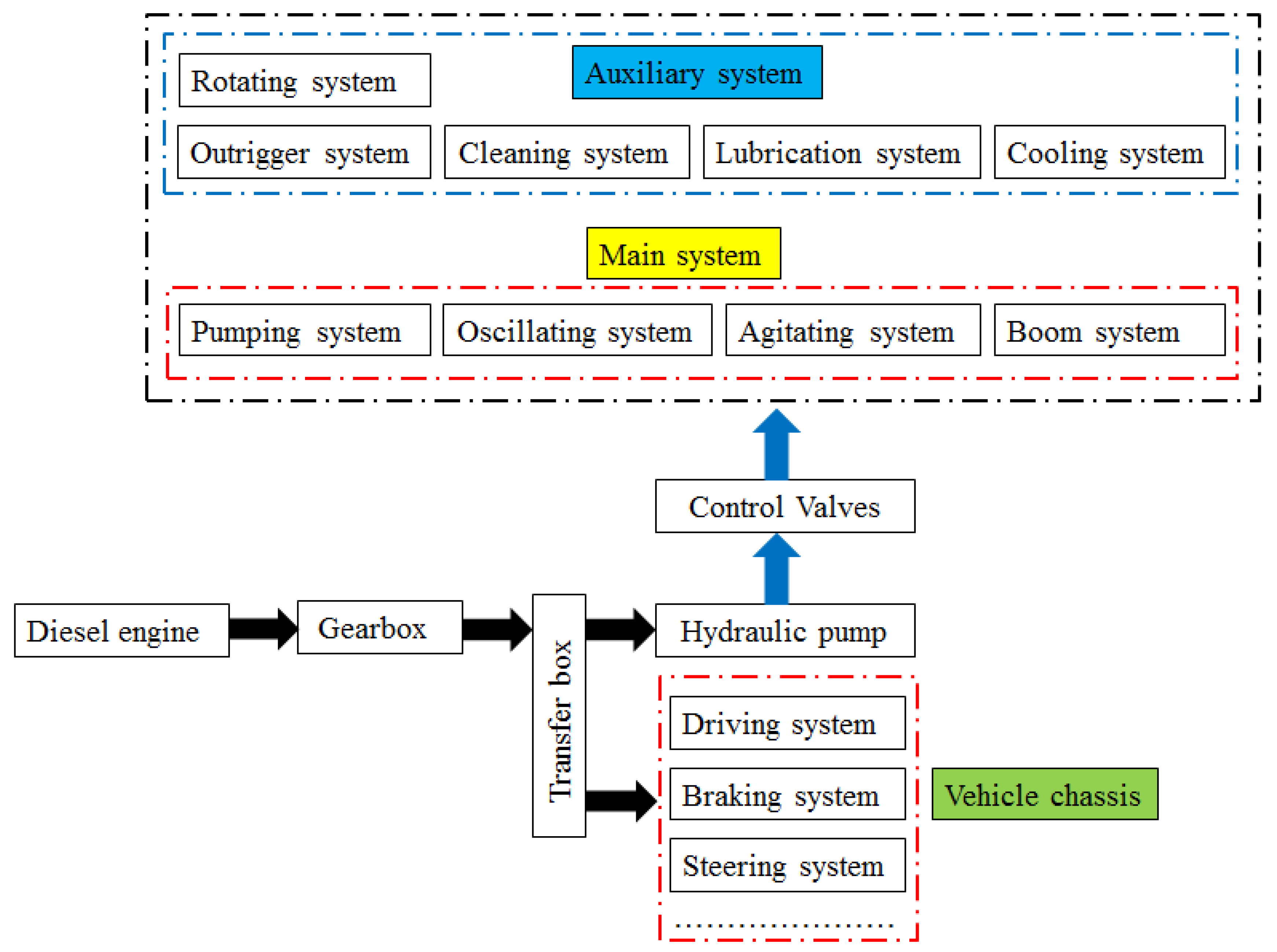
As shown in Figure 4, besides the structure of the trailer concrete pump, the gearbox, transfer box and vehicle chassis are included in the structure of the transported concrete pump. The transfer box is used to distribute mechanical power from the gearbox between vehicle chassis and hydraulic pump.
The transported concrete pump has two work conditions: driving condition and pumping condition. When working in the driving condition, by operating the transfer box, the channel from the gearbox to vehicle chassis is linked but the channel from the gearbox to the hydraulic pump is meanwhile cut off. When working in the pumping condition, by operating the transfer box, the channel from the gearbox to the hydraulic pump is linked but the channel from the gearbox to the vehicle chassis is meanwhile cut off.
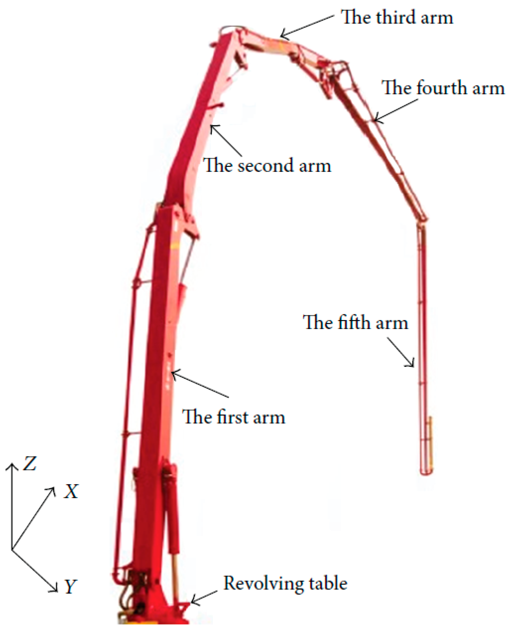
As shown in Figure 5, besides the structure of the transported concrete pump, the rotating system and boom system are included in the structure of the truck-mounted concrete pump. Figure 6 shows that boom system consists of booms and cylinders together with conveying pipes for delivering fresh concrete. The boom system is mounted on a rotating platform, and it can rotate 365° with the rotating platform. Each boom can rotate around its own axis. By combining the boom system and rotating system, fresh concrete can be poured to any expected position.
Similar to the transported concrete pump, the truck-mounted concrete pump also has two work conditions: driving condition and pumping condition. In addition, when working in the pumping condition, the hydraulic motor will drive the rotating platform to rotate and the cylinders linking booms will drive the corresponding boom to extend or retract so that it can ensure that fresh concrete can be transported to an expected position.
3.2. Analysis of Energy Consumption Ways
As mentioned above, the trailer concrete pump just has the pumping condition. Both transported concrete pump and truck-mounted concrete pump have two work conditions: driving condition and pumping condition. Since when working in driving conditions, there have been a number of studies on energy conservation about vehicles, this paper only focuses on analyzing energy consumption ways when working in pumping conditions.
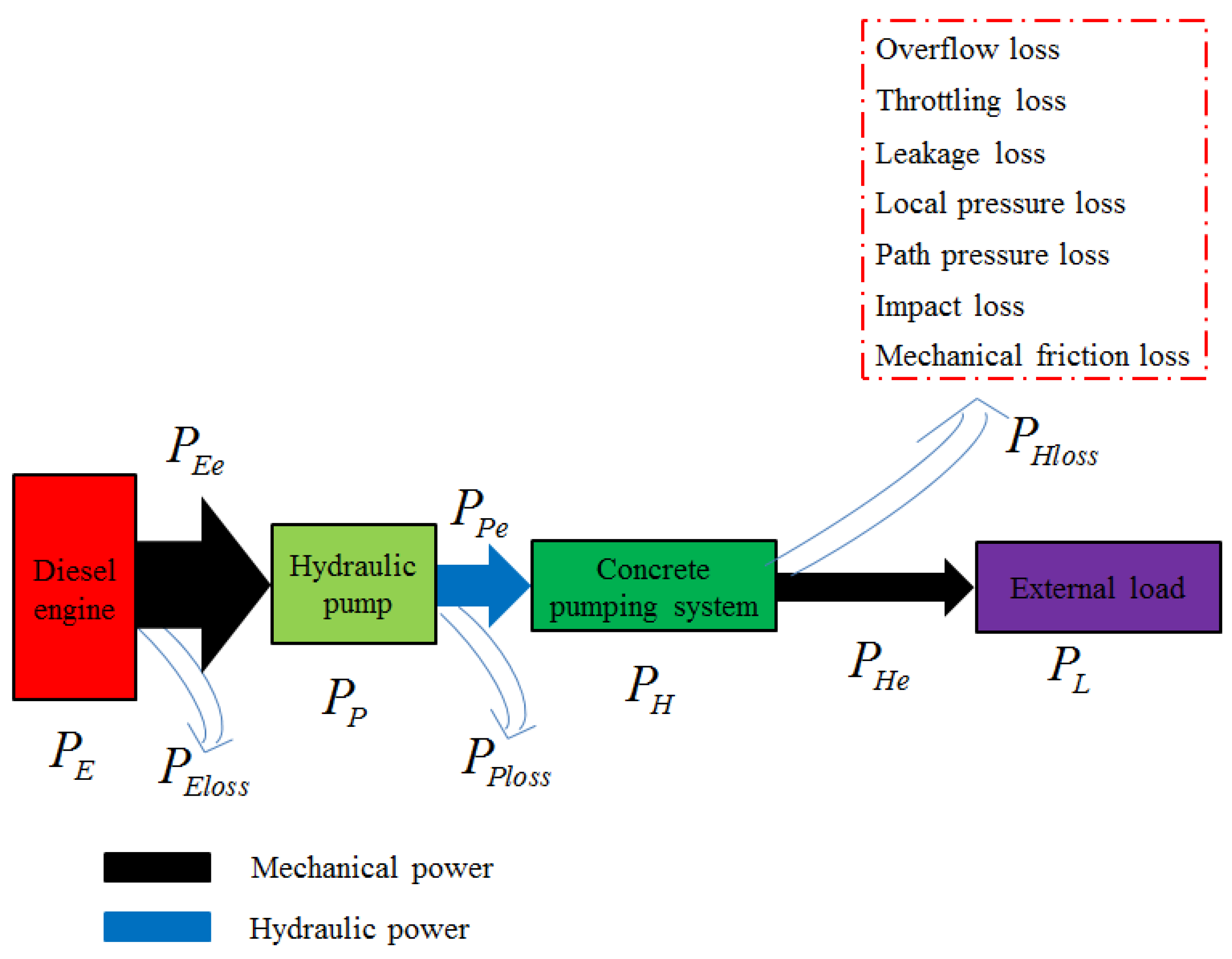
The energy flow route of the trailer concrete pump, transported concrete pump and truck-mounted concrete pump power flow route can be seen in Figure 7 and Figure 8. It can be seen that the energy provided by diesel engine flows through the hydraulic pump into the concrete pumping system, and finally drives the external load. With regard to the trailer concrete pump, the diesel engine and hydraulic pump are directly linked. As for transported concrete pump and truck-mounted concrete pump, the diesel engine is linked with the gearbox, then with the transfer box and then with the hydraulic pump. When mechanical power is inputted into the hydraulic pump, it thus rotates so that mechanical power is converted to hydraulic power. Oil, as the medium of the hydraulic system realizing energy converting, flows along oil pipes and through control valves and into cylinders or hydraulic motors to drive the external load. The energy consumption includes mechanical friction loss, impact loss, path pressure loss, local pressure loss, leakage loss, throttling loss and overflow loss.
3.2.1. Mechanical Friction Loss
When diesel engine works normally, there is friction that happens between the cylinder liner and piston ring. Commonly, an axial plunger pump is used in concrete pumps, so friction occurs on three key friction pairs: plunger and cylinder bore, cylinder block and port plate, slipper and swash plat. For the cylinder, there are two friction pairs, namely cylinder barrel and piston, piston rod and cylinder head, where friction happens. With regard to hydraulic motors used in the agitating system and rotating system, friction occurs between the motion part and static part. The boom system cylinders are mounted in rotary joints to connect two adjacent booms; therefore, friction happens in these rotary joints. Since the diesel engine is linked to the hydraulic pump directly or through the gearbox and transfer box by coupling, friction definitely occurs. In a word, mechanical friction loss mainly exists in the internal of the diesel engine and hydraulic pump, cylinders and hydraulic motors and rotary joints. The energy flowing path is from diesel engine to hydraulic pump (Figure 7) or from diesel engine to gearbox to transfer box to hydraulic pump (Figure 8).
3.2.2. Impact Loss
At present, the pumping system of concrete pumps is mainly a double-cylinder reciprocating piston pump driven by hydraulic pressure. The successful pumping of fresh concrete is accomplished by alternating two cylinders. When changing the control signal of the control valve to change its working position quickly, one cylinder pumping concrete would shift to sucking fresh concrete, and the other cylinder sucking fresh concrete would shift to pumping concrete. At the time when the control valve changes the working position, since the sudden changing of the external load, and oil in oil pipes cannot change their direction rapidly, hydraulic pressure in the corresponding oil pipes would abruptly shift from high value to low value or from low value to high value. The instantaneous high pressure caused by the rapid changing of oil flow is much higher than normal working pressure, even several times higher than the normal working pressure, which forms a hydraulic impact. After the oil absorbs part of the hydraulic impact, its temperature would increase quickly, thus causing system leakage and energy loss.
The oscillation system is used to control the swing of the S-tube to connect the concrete cylinder of the pumping system by operating two oscillation cylinders under hydraulic pressure. The direction changing time of the oscillation system is very short. When changing the working position of the control valve, the inertial force caused by fresh concrete in the S-tube during the swing process would lead to pressure in the oscillation system rising abruptly, thus resulting in a hydraulic impact.
Moreover, when the rotating system works in the braking mode and the agitating system changes its agitating direction and outrigger system, cleaning system, lubrication system, etc., and they shift their direction, an impact would inevitably occur, consequently consuming some energy and causing impact loss.
3.2.3. Path Pressure Loss
When oil flows through the same diameter pipes, i.e., pipes linking hydraulic pump and control valves and cylinders or hydraulic motors, due to friction between oil and pipes together with the interaction of oil particles under the viscosity of oil, a path pressure loss would inevitably occur in these pipes.
3.2.4. Local Pressure Loss
When the cross section area of the hydraulic components of concrete pumps change abruptly, such as elbow of pipes, joint of pipes, cylinder inlet or outlet, once hydraulic oil flows through these sections, since its direction and velocity would change abruptly and thus forms some whirlpool and cavitation, oil particles would also crash with each other, so that results in local pressure loss.
3.2.5. Leakage Loss
Leakage exists in all hydraulic systems of concrete pumps mainly including a pumping system, oscillation system, boom system, outrigger system and agitating system. Generally, the leakage amount increases with the increase in temperature and pressure. Especially, under the high external load thus the high pressure of system, leakage loss would share a certain proportion of energy consumption.
3.2.6. Throttling Loss
When the rotating system works and the rotating platform rotates to drive the boom system to an expected position, at this time, the rotating system needs to be braked. Since boom system has a large inertial force, during the braking process, the inertial of pressure oil and motion mechanism also compel the actuator hydraulic motor to keep rotating. Meanwhile it acts upon the oil in the return chamber and thus increases pressure in the return chamber. In fact, the pressure in the return chamber can be several times the normal working pressure. Under high pressure, oil would be squeezed from the opening gap of the control valve, thus a throttling loss occurs and converts the inertial force of the motion mechanism to heat consumption. In addition, for adjusting the extending or retracting velocity of cylinder linking two adjacent booms, throttle valves are employed so that throttling loss exists.
3.2.7. Overflow Loss
Relief valves are indispensably employed in the pumping system, oscillation system, agitating system, etc., to assure safety of the subsystem mentioned above. Once the system pressure exceeds a set value, relief valves are opened and overflow begins. Furthermore, balance valves are widely used in a rotating system and boom system to lock the working position of the rotating platform and booms. If pressure caused by the load of the rotating system and boom system is higher than the set value of corresponding balance valves, it thus results in overflow loss.
3.2.8. Power Matching Loss
Currently, no matter what work condition concrete pump is in, diesel engine always works in the same fuel consumption mode, but cannot be regulated reasonably according to different load, which results in diesel engine works in the area of high fuel consumption ratio long term. The original reason is that the output power of diesel engine cannot match with the absorption power of hydraulic pump, thus causes power of diesel engine cannot be utilized fully and results in energy loss.
4. Developments of Energy Conservation of Concrete Pump
According to the results of the literature search, the methods for energy conservation of concrete pumps can be classified into three types: the power matching approach, dual-fuel approach and dual power approach, as shown in Table 1.
4.1. Power Matching Approach
The core idea of the power matching approach is to match the diesel engine, the hydraulic pump and the load by adjusting the speed of the diesel engine and the displacement of the hydraulic pump, so that the diesel engine can work near the economic curve, and the hydraulic pump can fully absorb the power of the diesel engine, so as to improve the working efficiency of the whole machine and reduce fuel consumption. The schematic of the power matching approach of energy conservation for concrete pumps is shown in Figure 9.
Yang et al. [31] proposed the power matching control strategy of hydraulic pumps and diesel engines based on the analysis of the complex operating conditions of the truck-mounted concrete pump and the working characteristics of the diesel engine. When the load changes, the speed induction fuzzy control is adopted. By adjusting the speed of the diesel engine and the displacement of the hydraulic pump, the diesel engine can work near the economic curve, and the hydraulic pump can fully absorb the power of the diesel engine. By properly controlling the hydraulic pump and diesel engine, the power utilization rate is improved, thus improving the efficiency of the whole machine and the reliability of the diesel engine. According to the working condition analysis and fuel consumption test results of the truck-mounted concrete pump in the assessment, the proposed power matching control strategy is expected to reduce the fuel consumption of the whole machine by more than 10%.
Ye et al. [32,33] proposed a global power matching strategy based on engine fuel consumption rate and hydraulic pump efficiency to solve the problems of low efficiency and high-energy consumption of truck–mounted concrete pumps. The law of load change was summarized by mathematical statistics. The fuel consumption curve of diesel engine was drawn through bench test. The efficient working area of the hydraulic pump under different pressure, rotating speed and displacement was defined through the efficiency test. Based on a genetic algorithm, the combination optimization of engine fuel consumption rate and hydraulic pump efficiency was realized, and the engine speed and hydraulic pump displacement were jointly adjusted, so that the output control index changed adaptively in real time with the change in load conditions, so as to ensure that all components worked in the high-efficiency zone at the same time. The comparison test results of the fuel consumption for the new and old power matching strategies showed that in the area where the pumping capacity is 10~80 m3/h, the truck-mounted concrete pump has remarkable energy-saving effect, the fuel-saving rate could reach 22~46%, and the comprehensive fuel-saving rate was 16%.
In order to overcome the time varying and uncertain factors of the parameters of the concrete pumping system and the sudden change in the load, Ye et al. [34] proposed a two-parameter control strategy of engine speed and hydraulic pump displacement, which improved the rapidity and stability of the response of the control system. Through the field test, it was concluded that the load of the pumping system of the truck-mounted concrete pump had the characteristics of periodicity and mutation. Through the fuel consumption test, it was found that the fluctuation of the engine speed had a serious impact on the fuel consumption. Based on the dynamic equation of the system, a pressure differential induction reversing two-parameter control system was designed, which realized the double closed-loop control of the engine speed and the hydraulic pump displacement of the truck-mounted concrete pump. The test showed that the average fuel consumption was reduced by 5% by using the dual-parameter control strategy.
Xia et al. [35] designed the energy-saving control system of truck-mounted concrete pump based on the power matching strategy of engine and hydraulic pump. The system took energy saving as the control goal to realize the joint regulation of the engine and hydraulic pump. The controller of the concrete pump truck could automatically adjust the output power of the engine according to the change in the actual working conditions, and maintained a good match with the load, so that the engine always ran at the best working point or the best working area, so that the output power of the engine could be fully utilized. The test data showed that when the working displacement of the concrete pump truck was in the range of 10~70%, the energy-saving effect was significant, and the fuel-saving rate could reach 22~46%. When the working displacement of the concrete pump truck was within 70~80%, the energy saving was average, and the fuel-saving rate was about 13%. When the working displacement of the concrete pump truck was 80~100%, the energy saving was not obvious, at about 1%. The average fuel-saving rate of the whole region was more than 20%.
According to the characteristics of the closed hydraulic system of the concrete pump truck, Shi et al. [36] proposed the energy-saving method of adopting adaptive PID control to control the engine speed and the displacement of the closed hydraulic pump on the basis of ensuring the system load flow and system power demand. The results showed that, according to the power and fuel consumption curve of the engine, the composite control of the engine speed and the displacement of the variable displacement pump under different working conditions could achieve good energy-saving effect on the premise of meeting the requirements of working conditions, especially in the middle and small power range of the load, the energy-saving effect was obvious, and the average energy saving was more than 15%.
In view of the shortage that the concrete pump truck uses a fixed gear for pumping, Shi et al. [37] proposed a method to select the optimal transmission ratio by automatically switching the gear of the gearbox according to the load during the pumping process. The comparison test of fuel consumption between the new and the old pumping control scheme was carried out. The test showed that when the pumping volume of the new scheme was 50~100%, the energy-saving effect was obvious, and the energy-saving was up to 11%.
Based on the research on the working characteristics of the truck-mounted concrete pump under various working conditions and the universal characteristics of the engine, Wang et al. [38] developed the power matching control technology of the whole machine based on the adaptive variable torque model, and incorporated the service subsystems of the whole machine (pumping, distribution, mixing, boom, etc.) into the power control system to achieve the perfect match between the power system of the whole machine and the multi-load external working conditions, which could ensure that the engine had a stable load rate under any working conditions, making the engine always work at the economical fuel consumption point. The test results showed that the proposed energy-saving technology could reduce the fuel consumption of truck-mounted concrete pump by more than 10%.
Cheng [39] proposed a power matching strategy by controlling diesel engine and hydraulic pump simultaneously. When the load changes, regulating the flowrate of the variable displacement pump reasonably and timely so that when the revolving speed of the diesel engine varies, the torque of the diesel engine can be adjusted and the diesel engine can work nearby the economical point. The test results showed that the average fuel-saving rate was about 20% by employing the proposed energy-saving technology.
Li et al. [40] proposed to use the interval setting matching method and speed induction control to carry out a power energy-saving matching control on the engine and hydraulic system to reduce the useless power loss of the engine, so that the matching control of the engine and hydraulic pump could be carried out automatically with the size of the load, thus reducing fuel consumption. The actual vehicle test showed that this power matching control method had a significant energy-saving effect, which made the truck-mounted concrete pump deliver the same amount of concrete under the same working conditions with a fuel-saving rate of 20%.
He et al. [41] used the BP neural network to establish the universal characteristic model for the engine of a certain type of truck-mounted concrete pump, and optimized the working conditions of this type of truck-mounted concrete pump and obtained the engine speed that best matched the hydraulic system under four working conditions. The test results showed that the optimized engine working conditions based on the model had an obvious fuel-saving effect, with a maximum fuel saving of 11.67%.
Jie et al. [42] proposed a global power matching energy-saving control strategy of concrete pump trucks based on the load operation mode. The engine speed and hydraulic pump displacement are jointly adjusted by a dedicated controller to achieve the matching between the engine, hydraulic pump and load. In the real vehicle application, the proposed strategy achieved more than 10% fuel-saving rate under 80% load pumping condition.
Zeng et al. [43] proposed to realize the energy-saving control strategy of matching an engine hydraulic pump load by adjusting the relationship between engine speed, hydraulic pump swashplate opening, hydraulic pump pressure and the number of commutations per minute, so as to improve the working efficiency of the whole machine and reduce fuel consumption. The test results show that the maximum fuel-saving rate can reach 31.79%.
Wu et al. [44] proposed an energy-saving control strategy to match the power of the engine and the hydraulic pump of the truck-mounted concrete pump. When the load changed, the engine could work near the economic curve by adjusting the engine speed and the displacement of the hydraulic pump, and the hydraulic pump could fully absorb the power of the engine. The results showed that the average oil-saving rate reached 26.5%.
Pu [45] put forward an energy-saving parameter matching strategy of a load adaptive power system, which dynamically adjusted the speed of engine and displacement of the hydraulic pump according to the change in load conditions, so that the engine always worked near the economic working curve. The test results showed that the proposed parameter matching strategy could effectively reduce the fuel consumption of the power system, and the average fuel-saving rate was more than 10%.
4.2. Dual-Fuel Approach
The dual-fuel approach means that two fuels are simultaneously fed into the internal combustion engine and mixed and burned in the internal combustion engine. The proportion of the two fuels is adjusted by the controller in real time according to the external load conditions, so as to reduce the consumption of fossil energy and reduce the emissions generated by burning fossil energy. The schematic of the dual-fuel approach of energy conservation for concrete pumps is shown in Figure 10.
Li et al. [46] studied the key technology in the application of oil and gas blended combustion technology on the truck-mounted concrete pump, in which, on the basis of the original diesel engine, a set of fuel supply and electric control systems was added, and the automatic matching energy-saving control strategy of the engine load rate was adopted, so that the truck-mounted concrete pump could realize the diesel and natural gas-blended combustion switching operation mode under both driving and pumping conditions. According to the statistics of all test data, the blended combustion engine consumed 770.5 L of diesel oil and 1360.53 cubic meters of gas at all speeds, and 2078.3 L of diesel oil in the pure diesel mode under the same conditions.
4.3. Dual-Power Approach
He et al. [47] stated that the dual-power approach referred to the method of using two power sources (internal combustion engine and electric motor). When the vehicle was operating in the field or it was inconvenient to use electricity, the engine provided power to drive the working device; When the vehicle worked in a narrow, closed space or flammable and explosive conditions, it could be switched to the electric motor working mode by connecting AC power and performing the corresponding operation, and the electric motor provided power to drive the working device, which could greatly improve the economy and exhaust emissions on the premise of meeting the safety and reliability of the equipment. The schematic of the dual-power approach of energy conservation for concrete pumps is shown in Figure 11.
In view of the problems existing in the application of emergency power, He et al. [31,47] proposed a dual-power hydraulic system composed of a diesel engine and electric motor. When the conventional hydraulic system driven by electric motor cannot work, the diesel engine provides emergency power to the emergency hydraulic system by the manual operation of the remote controller. Through the control of the hydraulic valve group, the coordinated action of each actuator is realized, and the boom retraction, concrete pumping and cleaning are completed. The prototype commissioning and construction site application show that the parameters and indicators of the proposed dual-power hydraulic system meet the expected design requirements, meet the emergency power requirements in construction, have high cost performance and convenient operation.
According to the above statistical results, it can obviously be seen that the power matching approach is the most widely used in energy conservation for concrete pumps, which indicates that this is a research hot spot. In addition, although there is less research on the dual-power approach and dual-fuel approach, it also provides a new research idea for this area of study. With the breakthrough of fuel technology and power technology, it is believed that the dual-power approach and dual-fuel approach will gradually be successfully applied.
5. Challenges with Energy Conservation of Concrete Pumps
A pumping system is a common part of trailer concrete pumps, transported concrete pumps and truck-mounted concrete pumps, and it works in a continuous periodical pumping process. From different working conditions of concrete pumps, it can obviously be concluded that load power varies periodically with different loads in a large range, and accordingly, the working condition of diesel engine also changes periodically, and therefore, diesel engine cannot always work in a high-efficiency region. This is the main reason that concrete pumps have low-fuel economy.
A hybrid power system including Petrol–Hydraulic hybrid and Petrol–Electric hybrid systems has the potential to improve fuel economy by operating diesel engine in a high-efficiency region. Petrol–Hydraulic hybrid consists of a diesel engine converting chemical energy to mechanical energy and a hydraulic motor converting hydraulic energy to mechanical energy, and Petrol–Electric hybrid consists of a diesel engine converting chemical energy to mechanical energy and an electric motor converting electrical energy to mechanical energy. Because hybrid power system can significantly improve fuel economy it has been applied successfully in buses [48,49,50,51,52], vehicles [53,54,55,56,57,58,59], hydraulic excavators [60,61,62,63,64,65,66], hydraulic cranes [67,68,69], hydraulic forklifts [70,71,72,73], etc. Equipping concrete pumps with a hybrid power system offers a feasible way to achieve better energy conservation efficiency. In this paper, we forecast some trends on energy conservation for concrete pumps.
5.1. Reasonable Selecting of Structure Type
The working conditions of concrete pumps are complex, and different concrete pumps have different load characteristics; thus, it may suit for a different type of hybrid power structure. The serial or parallel structure type of concrete pumps should be comprehensively compared according to different working conditions and load characteristics so that concrete pumps can achieve better energy conservation efficiency.
5.2. Reasonable Optimizing of Control Strategy
The control strategy plays an important role in energy conservation and emission reduction in concrete pumps. There are so many types of concrete pumps, and the same type of concrete pump has different working characteristics under different working conditions. Therefore, the control strategy of hybrid concrete pumps should be studied on the basis of analyzing the load characteristics of concrete pumps so that concrete pumps can obtain the anticipated efficiency of energy conservation.
5.3. Reasonable Matching of Component Parameters
A Petrol–Hydraulic hybrid or Petrol–Electric hybrid power concrete pump is a mechanic–electric–hydraulic integration product, and it exists for the definite coupling of mechanic, electric and hydraulic power. The working performance of the whole machine is to be improved greatly if the reasonable matching of each component parameters can be realized. Thus, it should analyze the coupling characteristic among components and further study the parameter matching method on the basis of analyzing the characteristics of each component which is used to compose a hybrid power concrete pump.
5.4. Reasonable Effectiveness of Energy Storage Component
The energy storage component which includes a storage battery, super capacitor or accumulator is the important part for a hybrid concrete pump, and its performance has great influence on the working performance of a hybrid concrete pump. Due to the working characteristics of large-load changing, frequent working, a bad working environment, etc., the requirements such as power density, energy density, storage capacity, working lifetime and reasonable use are raised as to the effectiveness of the energy storage component.
5.5. Reasonable Design of Energy Management System
The energy required by a hybrid concrete pump varies because of different working conditions and load characteristics during the working process. If a reliable energy management system distributing energy in different working stages can reasonably be designed, the target of energy conservation is to be eventually realized.
6. Conclusions and Future Work
This paper expounds the structure and working principle of concrete pumps, analyzes the energy consumption ways for concrete pumps, summarizes the developments in energy conservation for concrete pumps, and presents the challenges with energy conservation of concrete pumps.
The research results of this paper indicate that the power matching approach is the most widely used approach in energy conservation of concrete pumps. In addition, both the dual-power approach and dual-fuel approach provide a new research idea for energy conservation of concrete pumps even if the research on the two approaches is less. It is expected that the dual-power approach and dual-fuel approach will gradually be successfully applied with the breakthrough of fuel technology and power technology.
By selecting the structure type, optimizing the control strategy, matching component parameters, enhancing the effectiveness of the energy storage component and designing a reasonable energy management system, it can achieve the goal of energy conservation for concrete pumps.
In our future research work, we will deeply study the technology with regard to applying a hybrid power system for concrete pumps. Specifically, we will carefully study the structure type of a hybrid system suitable for concrete pumps, further study and optimize the control strategy, study the parameter matching method and study the energy storage system of a hybrid system for concrete pumps, as well as study its energy management system.
Author Contributions
Conceptualization, H.L.; methodology, H.L.; validation, Q.Z.; formal analysis, Q.Z.; investigation, Q.Z.; writing—original draft preparation H.L.; writing—review and editing, Q.Z.; supervision, Q.Z.; funding acquisition, H.L. All authors have read and agreed to the published version of the manuscript.
Funding
This research received no external funding.
Data Availability Statement
The data presented in this study are available on request from the corresponding author.
Acknowledgments
This work is supported by the National Natural Science Foundation of China (grant number 51365008); the Joint Foundation of Science and Technology Department of Guizhou Province (grant number Qiankehe LH Zi (2015)7658). The authors are grateful to them for their support.
Conflicts of Interest
The authors declare no conflict of interest.
Nomenclature
| Power of diesel engine | |
| Power loss of diesel engine | |
| Effective power of diesel engine | |
| Power of hydraulic pump | |
| Power loss of hydraulic pump | |
| Effective power of hydraulic pump | |
| Power of concrete pumping system | |
| Power loss of concrete pumping system | |
| Effective power of concrete pumping system | |
| Power of external load | |
| Power of gearbox | |
| Power loss of gearbox | |
| Effective power of gearbox | |
| Power of transfer box | |
| Power loss of transfer box | |
| Effective power of transfer box |
References
- Mechtcherine, V.; Nerella, V.N.; Kasten, K. Testing pumpability of concrete using Sliding Pipe Rheometer. Constr. Build. Mater. 2014, 53, 312–323. [Google Scholar] [CrossRef]
- Kim, J.S.; Kwon, S.H.; Jang, K.P.; Choi, M.S. Concrete pumping prediction considering different measurement of the rheological properties. Constr. Build. Mater. 2018, 171, 493–503. [Google Scholar] [CrossRef]
- Sun, X.; Ye, H.; Fei, S. A closed-loop detection and open-loop control strategy for booms of truck-mounted concrete pump. Autom. Constr. 2013, 31, 265–273. [Google Scholar] [CrossRef]
- Choi, M.S.; Kim, Y.J.; Jang, K.P.; Kwon, S.H. Effect of the coarse aggregate size on pipe flow of pumped concrete. Constr. Build. Mater. 2014, 66, 723–730. [Google Scholar] [CrossRef]
- Choi, M.S.; Kim, Y.S.; Kim, J.H.; Kim, J.S.; Kwon, S.H. Effects of an externally imposed electromagnetic field on the formation of a lubrication layer in concrete pumping. Constr. Build. Mater. 2014, 61, 18–23. [Google Scholar] [CrossRef]
- Wu, Y.; Li, W.; Liu, Y. Fatigue life prediction for boom structure of concrete pump truck. Eng. Fail. Anal. 2016, 60, 176–187. [Google Scholar] [CrossRef]
- Choi, M.; Roussel, N.; Kim, Y.; Kim, J. Lubrication layer properties during concrete pumping. Cem. Concr. Res. 2013, 45, 69–78. [Google Scholar] [CrossRef]
- Choi, M.; Ferraris, C.F.; Martys, N.S.; Lootens, D.; Bui, V.K.; Hamilton, H.R.T. Metrology Needs for Predicting Concrete Pumpability. Adv. Mater. Sci. Eng. 2015, 2015, 10. [Google Scholar] [CrossRef] [Green Version]
- Nerella, V.N.; Mechtcherine, V. Virtual Sliding Pipe Rheometer for estimating pumpability of concrete. Constr. Build. Mater. 2018, 170, 366–377. [Google Scholar] [CrossRef]
- Tang, H.B.; Ren, W. Research on rigid-flexible coupling dynamic characteristics of boom system in concrete pump truck. Adv. Mech. Eng. 2015, 7, 7. [Google Scholar] [CrossRef]
- Jung, T.; Raduenz, H.; Krus, P.; De Negri, V.J.; Lee, J. Boom energy recuperation system and control strategy for hydraulic hybrid excavators. Autom. Constr. 2022, 135, 104046. [Google Scholar] [CrossRef]
- Yu, Y.X.; Do, T.C.; Park, Y.; Ahn, K.K. Energy saving of hybrid hydraulic excavator with innovative powertrain. Energy Convers. Manag. 2021, 244, 114447. [Google Scholar] [CrossRef]
- Li, J.; Zhao, J. Energy recovery for hybrid hydraulic excavators: Flywheel-based solutions. Autom. Constr. 2021, 125, 103648. [Google Scholar] [CrossRef]
- Do, T.C.; Dang, T.D.; Dinh, T.Q.; Ahn, K.K. Developments in energy regeneration technologies for hydraulic excavators: A review. Renew. Sustain. Energy Rev. 2021, 145, 111076. [Google Scholar] [CrossRef]
- Atashi Khoei, A.; Süral, H.; Tural, M.K. Energy minimizing order picker forklift routing problem. Eur. J. Oper. Res. 2023, 307, 604–626. [Google Scholar] [CrossRef]
- Zajac, P.; Rozic, T. Energy consumption of forklift versus standards, effects of their use and expectations. Energy 2022, 239, 122187. [Google Scholar] [CrossRef]
- Cheng, L.L.; Zhao, D.X.; Li, T.Y.; Wang, Y. Modeling and simulation analysis of electric forklift energy prediction management. Energy Rep. 2022, 8, 353–365. [Google Scholar] [CrossRef]
- Zhao, N.; Fu, Z.R.; Sun, Y.; Pu, X.N.; Luo, L. Digital-twin driven energy-efficient multi-crane scheduling and crane number selection in workshops. J. Clean. Prod. 2022, 336, 130175. [Google Scholar] [CrossRef]
- Vlahopoulos, D.; Bouhouras, A.S. Solution for RTG crane power supply with the use of a hybrid energy storage system based on literature review. Sustain. Energy Technol. Assess. 2022, 52, 102351. [Google Scholar] [CrossRef]
- Tan, C.; Yan, W.; Yue, J. Quay crane scheduling in automated container terminal for the trade-off between operation efficiency and energy consumption. Adv. Eng. Inform. 2021, 48, 101285. [Google Scholar] [CrossRef]
- Kusakana, K. Optimal energy management of a retrofitted Rubber Tyred Gantry Crane with energy recovery capabilities. J. Energy Storage 2021, 42, 103050. [Google Scholar] [CrossRef]
- Kusakaka, K.; Phiri, S.F.; Numbi, B.P. Optimal energy management of a hybrid diesel generator and battery supplying a RTG crane with energy recovery capability. Energy Rep. 2021, 7, 4769–4778. [Google Scholar] [CrossRef]
- Shafikhani, I.; Åslund, J. Energy management of hybrid electric vehicles with battery aging considerations: Wheel loader case study. Control. Eng. Pract. 2021, 110, 104759. [Google Scholar] [CrossRef]
- Comino, F.; Ruiz de Adana, M.; Peci, F. Energy saving potential of a hybrid HVAC system with a desiccant wheel activated at low temperatures and an indirect evaporative cooler in handling air in buildings with high latent loads. Appl. Therm. Eng. 2018, 131, 412–427. [Google Scholar] [CrossRef]
- Oh, K.; Yun, S.; Ko, K.; Ha, S.; Kim, P.; Seo, J.; Yi, K. Gear ratio and shift schedule optimization of wheel loader transmission for performance and energy efficiency. Autom. Constr. 2016, 69, 89–101. [Google Scholar] [CrossRef]
- Oh, K.; Kim, H.; Ko, K.; Kim, P.; Yi, K. Integrated wheel loader simulation model for improving performance and energy flow. Autom. Constr. 2015, 58, 129–143. [Google Scholar] [CrossRef]
- SANY. 80 series trailer-mounted concrete pump Hbt8018c-5s. In SANY Trailer-Mounted Concrete Pump; S.H.I.C. Ltd., Ed.; SANY: Changsha, China, 2016. [Google Scholar]
- SANY. C8 series line pump SY5128THB-10020C-8S. In C8 Series Line Pump; S.H.I.C. Ltd., Ed.; SANY: Changsha, China, 2016. [Google Scholar]
- SANY. C8 series truck-mounted concrete pump SYM5330THBDZ 470C-8S. In SANY C8 Series Truck-Mounted Concrete Pump; S.H.I.C. Ltd., Ed.; SANY: Changsha, China, 2016. [Google Scholar]
- Jin, M.; Wu, D. Collision-Free and Energy-Saving Trajectory Planning for Large-Scale Redundant Manipulator Using Improved PSO. Math. Probl. Eng. 2013, 2013, 8. [Google Scholar] [CrossRef] [Green Version]
- Yang, Y.; Gao, R. Research on Power Matching and Energy Saving Control of the Truck Mounted Concrete Pump. Constr. Mach. Technol. Manag. 2017, 1, 111–114. [Google Scholar]
- Ye, M.; Yi, X.; Jiao, S. Energy Optimization by Parameter Matching for a Truck-mounted Concrete Pump. Energy Procedia 2016, 88, 574–580. [Google Scholar]
- Ye, M.; Yi, X.G.; Pu, D.L.; Jiao, S.J. Global power matching on truck-mounted concrete pump based on genetic algorithm. J. Jilin Univ. (Eng. Technol. Ed.) 2015, 45, 820–828. [Google Scholar]
- Ye, M.; Yi, X.G.; Pu, D.L.; Jiao, S.J. Double-parameter control on concrete pumps for pressure-difference-sensed inversion. Chin. J. Constr. Mach. 2015, 13, 217–223. [Google Scholar]
- Xia, Y.M.; Shi, P.F.; Zhao, Y.F.; Xie, X.Z.; Yang, X. Analysis and Research of Energy Saving Technology for Concrete Pump Truck. Mech. Res. Appl. 2014, 3, 20–22. [Google Scholar]
- Shi, F.; Shen, Q.; An, D. Research and conduct of power saving strategy on closed hydraulic system for mounted concrete pump truck. Constr. Mach. 2013, 1, 59–61, 66. [Google Scholar]
- Shi, P.; Zhu, J.; Deng, X. Study on Automatic Gear Control of Gearbox of Concrete Pump Truck. Road Mach. Constr. Mech. 2013, 4, 84–86. [Google Scholar]
- Wang, J.; Wan, L.; Chen, Q. Research on the Energy Saving Technology of the Truck Mounted Concrete Pump. Constr. Mach. Technol. Manag. 2012, 6, 98–101. [Google Scholar]
- Cheng, Z. Study on Power-Matching Control of the Concrete Pump Truck’s Power System. Master Thesis, Jiangsu University, Zhenjiang, China, 2011. [Google Scholar]
- Li, Z.X.; Wang, S.X.; Jiang, H.; Cheng, Z.S. Research on power-matching of energy-saving for power system of the concrete pump truck. Mach. Des. Manuf. 2011, 6, 76–78. [Google Scholar]
- He, S.; Yang, Y. Modeling of universal characteristics and optimization of operating conditions of concrete pump truck based on neural network. J. Cent. South Univ. (Sci. Technol.) 2010, 41, 1398–1404. [Google Scholar]
- Jie, L.; Zen, Y.. An Energy Saving Control Strategy for Operation of Concrete Pump Trucks. Constr. Mach. Equip. 2010, 41, 20–23. [Google Scholar]
- Zeng, Y.P.; Zeng, F.L.; Wang, C.; Liu, L.; Cai, Y. Research of Energy-saving Control Methods for Concrete Pump Trucks. Constr. Mach. Equip. 2010, 41, 20–24. [Google Scholar]
- Wu, S.; Zeng, F. Study on Energy Saving Control Strategy of Concrete Pump Truck. Heavy Truck. 2008, 4, 9–11. [Google Scholar]
- Pu, D. Study on the Energy-Saving Parameter Matching of Dynamic System of the Truck-Mounted Concrete Pump. Master Thesis, Chang’An University, Chang’An, China, 2009. [Google Scholar]
- Li, X.; Shu, Z.; Li, H. Research and Application on the Truck Mounted Concrete Pump with Dual Fuel Mixed Combustion and Energy-saving. Constr. Mach. Technol. Manag. 2014, 1, 94–98. [Google Scholar]
- He, J.; Zhang, W. A New Type Dual-power Hydraulic System and Its Application to Concrete Pump Trucks. Constr. Mach. 2018, 49, 52–57. [Google Scholar]
- Agrawal, A.; Gupta, R. Optimized sensor charge controller for bus voltage stabilization in hybrid battery-supercapacitor fed islanded microgrid system. J. Energy Storage 2023, 59, 106482. [Google Scholar] [CrossRef]
- Wang, Z.G.; Wei, H.Q.; Xiao, G.W.; Zhang, Y.T. Real-time energy management strategy for a plug-in hybrid electric bus considering the battery degradation. Energy Convers. Manag. 2022, 268, 116053. [Google Scholar] [CrossRef]
- Roth, M.; Franke, G.; Rinderknecht, S. Decentralised multi-grid coupling for energy supply of a hybrid bus depot using mixed-integer linear programming. Smart Energy 2022, 8, 100090. [Google Scholar] [CrossRef]
- Liu, Z.; Zhao, J.; Qin, Y.J.; Wang, G.W.; Shi, Q.; Wu, J.Y.; Yang, H. Real time power management strategy for fuel cell hybrid electric bus based on Lyapunov stability theorem. Int. J. Hydrogen Energy 2022, 47, 36216–36231. [Google Scholar] [CrossRef]
- Li, J.W.; Yang, L.M.; Yang, Q.Q.; Wei, Z.B.; He, Y.T.; Lan, H. Degradation adaptive energy management with a recognition-prediction method and lifetime competition-cooperation control for fuel cell hybrid bus. Energy Convers. Manag. 2022, 271, 116306. [Google Scholar] [CrossRef]
- Ye, Y.M.; Zhang, J.F.; Pilla, S.; Rao, A.M.; Xu, B. Application of a new type of lithium-sulfur battery and reinforcement learning in plug-in hybrid electric vehicle energy management. J. Energy Storage 2023, 59, 106546. [Google Scholar] [CrossRef]
- Xu, B.; Wang, H. A comparative analysis of adaptive energy management for a hybrid electric vehicle via five driving condition recognition methods. Energy 2023, 269, 126732. [Google Scholar] [CrossRef]
- Xiao, C.W.; Wang, B.; Zhao, D.; Wang, C.H. Comprehensive Investigation on Lithium Batteries for Electric and Hybrid-Electric Unmanned Aerial Vehicle Applications. Therm. Sci. Eng. Prog. 2023, 38, 101677. [Google Scholar] [CrossRef]
- Sun, X.L.; Fu, J.Q.; Yang, H.Y.; Xie, M.K.; Liu, J.P. An energy management strategy for plug-in hybrid electric vehicles based on deep learning and improved model predictive control. Energy 2023, 269, 126772. [Google Scholar] [CrossRef]
- Nassar, M.Y.; Shaltout, M.L.; Hegazi, H.A. Multi-objective optimum energy management strategies for parallel hybrid electric vehicles: A comparative study. Energy Convers. Manag. 2023, 277, 116683. [Google Scholar] [CrossRef]
- Huang, Y.; Hu, H.Q.; Tan, J.Q.; Lu, C.L.; Xuan, D.J. Deep reinforcement learning based energy management strategy for range extend fuel cell hybrid electric vehicle. Energy Convers. Manag. 2023, 277, 116678. [Google Scholar] [CrossRef]
- Huang, R.; He, H. Naturalistic data-driven and emission reduction-conscious energy management for hybrid electric vehicle based on improved soft actor-critic algorithm. J. Power Sources 2023, 559, 232648. [Google Scholar] [CrossRef]
- Ranjan, P.; Wrat, G.; Bhola, M.; Mishra, S.K.; Das, J. A novel approach for the energy recovery and position control of a hybrid hydraulic excavator. ISA Trans. 2020, 99, 387–402. [Google Scholar] [CrossRef] [PubMed]
- Yu, Y.; Ahn, K.K. Optimization of energy regeneration of hybrid hydraulic excavator boom system. Energy Convers. Manag. 2019, 183, 26–34. [Google Scholar] [CrossRef]
- Chen, Q.H.; Lin, T.L.; Ren, H.L.; Fu, S.J. Novel potential energy regeneration systems for hybrid hydraulic excavators. Math. Comput. Simul. 2019, 163, 130–145. [Google Scholar] [CrossRef]
- Chen, Q.; Lin, T.; Ren, H. Parameters optimization and control strategy of power train systems in hybrid hydraulic excavators. Mechatronics 2018, 56, 16–25. [Google Scholar] [CrossRef]
- Cao, T.F.; Russell, R.L.; Durbin, T.D.; Cocker, D.R.; Burnette, A.; Calavita, J.; Maldonado, H.; Johnson, K.C. Characterization of the emissions impacts of hybrid excavators with a portable emissions measurement system (PEMS)-based methodology. Sci. Total Environ. 2018, 635, 112–119. [Google Scholar] [CrossRef] [Green Version]
- Lin, T.L.; Huang, W.P.; Ren, H.L.; Fu, S.J.; Liu, Q. New compound energy regeneration system and control strategy for hybrid hydraulic excavators. Autom. Constr. 2016, 68, 11–20. [Google Scholar] [CrossRef]
- Kim, H.; Yoo, S.; Cho, S.; Yi, K. Hybrid control algorithm for fuel consumption of a compound hybrid excavator. Autom. Constr. 2016, 68, 1–10. [Google Scholar] [CrossRef]
- Corral-Vega, P.J.; García-Triviño, P.; Fernández-Ramírez, L.M. Design, modelling, control and techno-economic evaluation of a fuel cell/supercapacitors powered container crane. Energy 2019, 186, 115863. [Google Scholar] [CrossRef]
- Corral-Vega, P.J.; Fernández-Ramírez, L.M.; García-Triviño, P. Hybrid powertrain, energy management system and techno-economic assessment of rubber tyre gantry crane powered by diesel-electric generator and supercapacitor energy storage system. J. Power Sources 2019, 412, 311–320. [Google Scholar] [CrossRef]
- Ovrum, E.; Bergh, T.F. Modelling lithium-ion battery hybrid ship crane operation. Appl. Energy 2015, 152, 162–172. [Google Scholar] [CrossRef]
- Hsieh, C.-Y.; Pei, P.C.; Bai, Q.; Su, A.; Weng, F.-B.; Lee, C.-Y. Results of a 200 hours lifetime test of a 7 kW Hybrid–Power fuel cell system on electric forklifts. Energy 2021, 214, 118941. [Google Scholar] [CrossRef]
- Girbés, V.; Armesto, L.; Tornero, J. Path following hybrid control for vehicle stability applied to industrial forklifts. Robot. Auton. Syst. 2014, 62, 910–922. [Google Scholar] [CrossRef] [Green Version]
- Hosseinzadeh, E.; Rokni, M.; Advani, S.G.; Prasad, A.K. Performance simulation and analysis of a fuel cell/battery hybrid forklift truck. Int. J. Hydrogen Energy 2013, 38, 4241–4249. [Google Scholar] [CrossRef]
- Keränen, T.M.; Karimaki, H.; Viitakangas, J.; Vallet, J.; Ihonen, J.; Hyotyla, P.; Uusalo, H.; Tingelof, T. Development of integrated fuel cell hybrid power source for electric forklift. J. Power Sources 2011, 196, 9058–9068. [Google Scholar] [CrossRef]
Figure 1.
The basic research process.

Figure 2.
Three types of concrete pumps. (a) Trailer concrete pumps [27]. (b) Transported concrete pumps [28]. (c) Truck-mounted concrete pumps [29].

Figure 3.
Structure diagram of trailer concrete pump.

Figure 4.
Structure diagram of transported concrete pump.

Figure 5.
Structure diagram of truck-mounted concrete pump.

Figure 6.
Boom system of truck-mounted concrete pump [30].
Figure 6.
Boom system of truck-mounted concrete pump [30].

Figure 7.
Energy flow route of trailer concrete pump.

Figure 8.
Energy flow route of transported/truck-mounted concrete pump.

Figure 9.
Schematic of power matching approach of energy conservation for concrete pumps. (a) Power matching approach of trailer concrete pump. (b) Power matching approach of transported/truck-mounted concrete pump.
Figure 9.
Schematic of power matching approach of energy conservation for concrete pumps. (a) Power matching approach of trailer concrete pump. (b) Power matching approach of transported/truck-mounted concrete pump.

Figure 10.
Schematic of dual-fuel approach of energy conservation for concrete pumps. (a) Dual-fuel approach of trailer concrete pump. (b) Dual-fuel approach of transported/truck-mounted concrete pump.
Figure 10.
Schematic of dual-fuel approach of energy conservation for concrete pumps. (a) Dual-fuel approach of trailer concrete pump. (b) Dual-fuel approach of transported/truck-mounted concrete pump.


Figure 11.
Schematic of dual-power approach of energy conservation for concrete pumps. (a) Dual-power approach of trailer concrete pump. (b) Dual-power approach of transported/truck-mounted concrete pump.
Figure 11.
Schematic of dual-power approach of energy conservation for concrete pumps. (a) Dual-power approach of trailer concrete pump. (b) Dual-power approach of transported/truck-mounted concrete pump.


Table 1.
Classification of methods for energy conservation of concrete pumps.
| Type | Fuel-Saving Rate | Title |
|---|---|---|
| Power matching approach | 10% | Research on Power Matching and Energy Saving Control of the Truck Mounted Concrete Pump [31] |
| 16% | Energy Optimization by Parameter Matching for a Truck Mounted Concrete Pump [32] | |
| 16% | Global power matching on truck- mounted concrete pump based on genetic algorithm [33] | |
| 5% | Double-parameter control on concrete pumps for pressure-difference-sensed inversion [34] | |
| 20% | Analysis and Research of Energy Saving Technology for Concrete Pump Truck [35] | |
| 15% | Research and conduct of power saving strategy on closed hydraulic system for mounted concrete pump truck [36] | |
| 11% | Study on Automatic Gear Control of Gearbox of Concrete Pump Truck [37] | |
| 10% | Research on the Energy Saving Technology of the Truck Mounted Concrete Pump [38] | |
| 20% | Study on power-matching control of the concrete pump truck’s power system [39] | |
| 20% | Research on power-matching of energy-saving for power system of the concrete pump truck [40] | |
| 11.67% | Modeling of universal characteristics and optimization of operating conditions of concrete pump truck based on neural network [41] | |
| 10% | An Energy Saving Control Strategy for Operation of Concrete Pump Trucks [42] | |
| 31.79% | Research of Energy-saving Control Methods for Concrete Pump Trucks [43] | |
| 26.5% | Study on Energy Saving Control Strategy of Concrete Pump Truck [44] | |
| 10% | Study on the energy-saving parameter matching of dynamic system of the truck-mounted concrete pump [45] | |
| Dual-fuel approach | 63% | Research and Application on the Truck Mounted Concrete Pump with Dual Fuel Mixed Combustion and Energy-saving [46] |
| Dual-power approach | __ | A New Type Dual-power Hydraulic System and Its Application to Concrete Pump Trucks [47] |
Disclaimer/Publisher’s Note: The statements, opinions and data contained in all publications are solely those of the individual author(s) and contributor(s) and not of MDPI and/or the editor(s). MDPI and/or the editor(s) disclaim responsibility for any injury to people or property resulting from any ideas, methods, instructions or products referred to in the content. |
© 2023 by the authors. Licensee MDPI, Basel, Switzerland. This article is an open access article distributed under the terms and conditions of the Creative Commons Attribution (CC BY) license (https://creativecommons.org/licenses/by/4.0/).
Share and Cite
MDPI and ACS Style
Liu, H.; Zhao, Q. Review on Energy Conservation of Construction Machinery for Pumping Concrete. Processes 2023, 11, 842. https://doi.org/10.3390/pr11030842
AMA Style
Liu H, Zhao Q. Review on Energy Conservation of Construction Machinery for Pumping Concrete. Processes. 2023; 11(3):842. https://doi.org/10.3390/pr11030842
Chicago/Turabian StyleLiu, Huiyong, and Qing Zhao. 2023. "Review on Energy Conservation of Construction Machinery for Pumping Concrete" Processes 11, no. 3: 842. https://doi.org/10.3390/pr11030842
Note that from the first issue of 2016, this journal uses article numbers instead of page numbers. See further details here.