
Study on Enhanced Heat Transfer of the Convex Columns in the Cooling Channel of Motorized Spindle Based on Field Synergy

School of Mechanical Engineering, Xi’an Jiaotong University, Xi’an 710054, China
*
Author to whom correspondence should be addressed.
Processes 2023, 11(8), 2431; https://doi.org/10.3390/pr11082431
Submission received: 5 June 2023
/
Revised: 17 July 2023
/
Accepted: 28 July 2023
/
Published: 12 August 2023
(This article belongs to the Special Issue High-Performance Machining Processes: From Mechanisms to Equipment)
Abstract
:The cooling performance of motorized spindles plays an important role in accuracy in high-speed machining. Aiming at improving the cooling performance of traditional motorized spindles, convex columns were built in the cooling channel. Based on field synergy, the effects of quadrilateral, circular and triangular convex columns on the heat transfer performance of the cooling channel were analyzed numerically. We also compared the pressure drop between the inlet and outlet under the same conditions. The results show that the cooling channels with triangular convex columns provide the best cooling effect with the smallest increase in area compared to quadrilateral convex columns and circular convex columns. The pressure drop in the cooling channels with a circular convex column is minimized. By optimizing the spacing of the convex column, the best effect was found at a spacing of 7 mm. By optimizing the angle of the top angle of the triangular column, it is found that the enhanced heat transfer effect is best at 120° when the heat transfer area is the same. In addition, when considering the addition of convex columns, it is important to ensure sufficient pressure drop to achieve a good cooling effect.
1. Introduction
A motorized spindle is one of the core components of CNC machine tools. Large amounts of heat will be generated by the built-in motor and high-speed bearings. If the heat is not effectively dissipated, it will lead to a temperature rise and large thermal stress, resulting in thermal error and deteriorating the machining accuracy. According to Bryan [1], thermal errors can account for 40–70% of the total errors. The proportion of errors caused by spindle heating in thermal errors is as high as 60–80% [2].
In order to reduce machining errors caused by heat generation of the spindle system, forced cooling is one of the most commonly used and effective technologies at present [3]. The current spindle cooling techniques are mainly divided into passive and active cooling techniques.
The common passive cooling method is to cool the spindle stator by using heat pipes or adding heat conduction channels. F. Li [4] et al. designed a shaft cooling structure of a grinding motorized spindle based on loop thermosyphons. The maximum temperature of the motor spindle was reduced by approximately 28%. Liang F et al. [5] proposed a central cooling structure for grinding a motorized spindle under the inspiration of the principle of miniature revolving heat pipes. The simulation results showed that the total deformation of the tool holder was reduced by 33.3%. Heat pipe cooling does not consume additional pump power and has good sealing performance for complex electric spindles. However, its structure and manufacturing quality have a great influence on the cooling effect of electric spindles. Moreover, it is difficult to adjust the cooling effect under different working conditions for a given heat pipe. The cost is also higher than the commonly used water-cooling technology.
Active cooling is mainly realized by adding a spiral or straight rectangular cooling channel between the spindle shell and the spindle stator as is shown in Figure 1. The spindle system is cooled by convective heat transfer between the coolant flowing through the channel and the spindle stator. For the traditional cooling channel structure, reducing the temperature of the coolant can significantly reduce the temperature rise of the spindle. S. N. Maurya [6] et al. studied the effect of coolant temperature on spindle error and found that the thermal deformation of the spindle is directly related to the coolant temperature and can affect the accuracy of thermal compensation. Obviously, a decrease in coolant temperature leads to an increase in energy consumption. C.H. Chien, J.Y. Jang [7] found through experiments that when the coolant flow rate increased from 0.24 L/min to 0.48 m/min and 0.72 L/min successively, the axial average maximum temperature of the spindle showed a slow decreasing trend. K.-Y. Li [8] et al. established the varied cooling oil volume method to reduce the thermal deformation of the spindle by adjusting the flow rate of cooling oil to match the spindle speed. In actual machining, the accuracy can be improved by 34–62% using this method. Zhang Lixiu [9] discovered that continuously increasing the flow rate of a coolant could not always effectively enhance the cooling performance. The spindle cooling effect of traditional cooling channels is limited.
Besides the flow rate and the chemical or physical characteristics of the coolant, the geometric characteristics of the cooling channel [10] also have impacts on the cooling effect. Some scholars tried to improve the cooling capacity by optimizing the macro and microgeometric characteristics of the cooling channel [11]. For example, K.-Y. Li et al. [12] used the doe method to optimize the size of the spindle cooling channels and verified the optimization through experiments. The result showed that the method can reduce spindle deformation by more than 40%. Xia C [13] designed a tree-shaped cooling channel based on fractal theory. Under the same pressure drop at the entrance and exit, the heat dissipation of the new channel was twice that of the traditional spiral cooling channel. Deng X [14,15] proposed a honeycomb cooling channel [14] and an insect pulse channel [15] with bionics theory. Compared with a traditional spiral cooling channel, the temperature uniformity of the honeycomb cooling channel was better, and the maximum temperature and minimum temperature of the insect pulse channel decreased by 17.8% and 4.6%, respectively. However, the new structure is often complicated, and its practicability and cost need to be verified through further experiments. Therefore, some scholars devoted themselves to improving the structure of the traditional spiral cooling channel. For example, a spiral reverse annular cooling channel was designed by Sleiti [16]. Under the same cooling flow rate, the maximum temperature of the heated surface was 63% lower than that of the continuous spiral cooling channel. Yang Tang [17] et al. added a convex column on the basis of the traditional simple channel structure. They found out that the convex columns could improve the cooling effect of the cooling channel by increasing turbulence intensity. In addition, Weber J, Shabi L [18] et al. studied the influence of the surface roughness of the cooling channel. When the roughness of the cooling channel was 100 microns, the heat transfer coefficient more than doubled compared with 50 microns, indicating that increasing the surface roughness has an obvious effect on the heat transfer.
In the field of microelectronics, some researchers often add spoilers in microchannels to improve the heat dissipation performance. Jin Wang [19] et al. proposed a novel combined structure with pin fins and vortex generators to enhance the thermal performance of an integrated microchannel heat sink. Fang Li [20] et al. investigated the field synergy and heat transfer performance of nanofluids in microchannels with non-uniformly perturbed cavities. The enhanced heat transfer mechanism in complex microchannels is analyzed based on the field synergy principle. Yunfei Yan [21] et al. proposed a novel fin-shaped pin fin array heat sink for improving micro-fluid cooling technology for electronic chip micro heat sinks, which improved the heat dissipation capacity of the micro heat sink.
Inspired by the study of fluids in microchannels in the field of microelectronics, in this paper, based on the traditional straight rectangular/spiral cooling channel of the spindle system, convex columns were proposed to be built in it. Under the analysis of field synergy theory, the shape and spacing of convex columns are designed. The optimal convex column parameters are optimized to enhance the effect of the heat transfer.
2. Cooling Channel Model and Field Synergy Principle
2.1. Cooling Channel Model of Motorized Spindle
Traditionally, the cooling water jackets of motorized spindles are straight, spiraled or U-shaped. They are mostly narrow and long. In this study, the spiral cooling water jacket was selected as the research object. The field synergy effect of the cooling channel of a motorized spindle is analyzed. Ignoring the radian and spiral angle of the channel, the cooling channel is simplified as shown in Figure 2 and Figure 3. The convex columns were set on the shell of the cooling channel and optimized to enhance heat dissipation.
Due to the convex columns, eddy currents are created in the channel, and the fluid state is changed. The water-cooling effect is greatly influenced by the shape, size, quantity and layout of the convex columns [17]. Considering the practical application, the shape of the convex should not be too complicated, so the shapes of the convex set in the cooling channel model in this paper are quadrilateral, cylindrical and triangular. Their cross-sections are regular quadrilateral, circle and regular triangle, respectively. The parameters of the convex columns are shown in Table 1. The convex columns are set in the center of the channel, with the sides of the quadrilateral post facing the direction of the cooling channel, and for the square triangular post, the top corners are facing the direction of the cooling channel development. The side lengths of each convex column are equal. Considering the effect of the height of the convex columns on the pressure drop, we set the height of the convex columns to 1.5 mm, which occupies 2/3 of the total thickness of the cooling channel.
2.2. Boundary Conditions and Grid Division
In order to simplify the numerical calculation process, the following assumptions and settings should be made. According to [22], it is known that the loss of electrical energy occurs in the rotor and stator during the operation of the spindle, and the amount of heat generated is constant at a constant rotational speed. Therefore, the heat source is assumed to be uniform in the model and is set to a constant heat flow density in the inner wall. Assuming that the model is in a constant temperature environment, the convective heat transfer coefficient of the stator shell exposed in the air is constant in the air.
Cooling water is incompressible and continuous. Its physical properties are invariable. The flow of cooling water in the channel has steady-state turbulence without viscous dissipation and phase transitions. The heat conduction in the solid region of the spindle jacket is steady. The solid material of the water jacket is stainless steel, and the thermal property of the material is linear and does not change with the temperature. Its properties are shown in Table 2.
- A heat flux of 30,000 W/m2, which is calculated according to a reference, is transferred from the heat source.
- The heat is dissipated by the forced convection of the cooling water in the cooling channel and natural convection with the surrounding air.
- The radiation is ignored.
- The air temperature is set at 25 °C, and the natural convection coefficient with the outer wall of the model is set at 9.7 W/(m2·K).
Other parameters are set as shown in Table 3.
A simplified simulation model was established to study the enhancement effect of convex columns on heat transfer in flow channels. The meshing result of the model was shown in Figure 4. Taking the model of quadrilateral convex columns as an example, 3,078,694 cells in the model are meshed in the model shown in Figure 4. In the meshing process, a boundary layer was added to the flow field to improve the calculation accuracy. The mesh quality was evaluated by using FLUENT; the minimum orthogonal quality is 1.16 and the maximum aspect ratio is 3.72. The meshing quality met the requirements.
The relationship between the temperature of the inner wall and the grid quantity is shown in Figure 5. Through the grid independence test, it was found that the number of grids over 4 × 10⁵ is reasonable, and the number of grids in our model meets all requirements.
2.3. Field Synergy Principle
The field synergy principle is a heat transfer enhancement theory proposed by Guo Z in 2003 [23]. Based on the synergistic effect of the heat flow field and velocity field, convective heat transfer in the cooling channel of a motorized spindle is studied.
The convection heat transfer between the coolant and the inner wall of the cooling system can be regarded as the two-dimensional steady laminar flow heat transfer problem as shown in Figure 6. When a constant temperature fluid flows through the wall, the fluid temperature T changes from the wall temperature to the prevailing temperature in a very thin region near the wall, where is the thermal boundary layer thickness. In the Cartesian coordinate system, the energy equation is as follows [24]:
where ρ is the fluid density, kg/m3; is the specific heat capacity, J/(kg·K); u and v are velocity components, m/s; and T is the temperature of the fluid, K.
By integrating the energy equation along the direction of thermal boundary layer thickness, we can obtain:
where is the thermal boundary layer thickness, m; U is the total velocity, m/s; and ∇T is the temperature gradient, K/m.
Parameters in Equation (2) were nondimensionalized; then,
where is the Reynolds number and Pr is the Prandtl number. β is defined as the synergistic angle of the local velocity vector and temperature gradient vector, which can be obtained according to Equation (4).
It is verified by Leng X [25] that the heat transfer is the same when the cooling water flows at the same flow rate towards and away from the heat transfer wall. Therefore, the synergy angle β can be limited to between 0° and 90°.
It can be seen from Equations (3) and (4) that when and Pr are constant, the heat transfer is enhanced as the integral term increases. In other words, when the size, velocity and properties of the cooling channel remain unchanged, the convective heat transfer can be enhanced by changing the fluid state inside the cooling channel.
The heat transfer effect of the coolant is not only related to the velocity and the temperature field in the flow field but also related to the synergistic effect. The smaller the synergistic angle β is, the better the synergistic effect is, and the heat transfer is enhanced when the properties and parameters of the coolant are unchanged.
3. Results and Analysis of Heat Transfer Simulation
3.1. Analysis of the Field Synergy for Different Shapes of Convex Columns
A simplified cooling channel model is established, and five triangular, quadrilateral and circular cross-section convex columns are set and distributed equidistantly in the channel. By using ANASY FLUENT 2021 R1, the field synergy of models with different convex columns was analyzed numerically (see Figure 7 and Figure 8). The solutions were imported into TECPLOT 360 EX 2022 R1. The field synergy function was calculated by using the UFD function of TECPLOT.
It can be seen from Figure 7 that at the inlet of the model, the value of β was small. This is because the temperature of the coolant is low, less heat is transferred by convection, and no stable drainage basin was formed. As the fluid flowed along the cooling channel, a stable basin was formed, and the β gradually increased. The value of β behind and around the convex columns is small, which means the synergistic effect between the fluid temperature field and the velocity field is enhanced.
By comparing the results in Figure 4, it can be known that the field synergy effects in the cooling channel are different with different shapes of convex columns. For the triangular convex columns, the main reduction area of the synergistic angle is extended in a quadrilateral shape. Meanwhile, the reduction areas of the synergistic angle after the quadrilateral and cylindrical convex columns were extended in a triangular shape.
According to Figure 8, at the sidewall of the cooling channel, the direction of the temperature gradient was almost perpendicular to the direction of fluid velocity. The synergy angle of the fluid inside the cooling channel was the largest, resulting in the poorest field synergy effect. When the fluid flowed through the convex columns, eddy currents were formed behind them, so the velocity vector of the fluid was greatly changed. Combined with Figure 7, it can be concluded that the field synergistic effect can be effectively enhanced by installing the convex columns in the cooling channel.
A series of cross-sections were set up in the model by using TECPLOT 360 EX 2022 R1 in order to quantitatively analyze the effect of the convex columns on fluid heat transfer enhancement along the cooling channel. These cross-sections were spaced at 1 mm intervals, and the total number was 100. Taking the model with triangular convex columns as an example, the average value of the synergy angle β for the 1st–100th cross-sections is shown in Figure 9.
Compared with the model of the cooling channel without convex columns, it can be seen from Figure 9 that the synergy angle of the cooling channel with convex columns was lower. At the position where the convex column is set, the average value of the synergy angle is about 5° lower than the no convex column model, which means the field synergy effect is significantly enhanced.
To compare the field synergistic effect of different convex columns in the cooling channel, the average values of β for 100 cross-sections and the temperatures of the inner wall surface at a steady state of four different models were calculated as shown in Figure 10. It can be seen from Figure 10 that the inner wall surface temperature of all three models after setting the convex columns is significantly lower than that of the cooling channel without convex columns. The inner wall surface temperatures of the triangular and quadrilateral convex models are the lowest (38.3 °C), and the inner wall surface temperature of the model with cylindrical convex columns is significantly higher than that of the other two. The mean synergy angle β of the model with triangular convex columns is the lowest (85.97°), and the average synergy angle β of the channel without convex columns is the highest (87.82°). It indicated that with convex columns, the synergistic effect of the temperature and velocity fields is enhanced, and the model with triangular convex columns has the best synergistic effect. This result is also confirmed in [17].
The addition of convex columns in the cooling channels leads to an increase in fluid resistance. At the same inlet flow rate, the pressure to be supplied is undoubtedly elevated. The inlet and outlet pressure drops for four different structures of the cooling channel are shown in Figure 11. We can find that although the circular convex column has the worst field synergies and obtained wall temperatures compared to the other two, the advantage of its shape leads to a relatively small increase in pressure drop. The pressure drop for the triangular convex column is less than that of the quadrilateral column, which, again, is able to show that the triangular shape is more effective than the quadrilateral shape for equal side lengths.
When a convex column is set up in the cooling channel, the heat transfer area between the fluid and the solid also increases. The increased heat transfer areas of different models were calculated as shown in Table 4.
When five convex columns are set in the cooling channel, it can be seen from Table 4 that the increased heat transfer area in the channel with triangular convex columns (112.5 mm2) was smaller than that with quadrilateral convex columns (150 mm2), while the average synergy angle was lower. The increase in heat transfer area also affects the final heat transfer. In this process, the triangular column has the smallest increase in heat transfer area, indicating that the advantage of its field synergies in the flow field outweighs the additional heat transfer area of the quadrilateral column. So, it can be seen that the triangular perturbed column has the best combined effect.
3.2. Optimization of the Intervals between Convex Columns
The intervals between the convex columns also affect the cooling capacity of the cooling channel. Based on 3.1, the triangular convex columns model was selected for spacing optimization. The change in the synergy angle along the cooling channel when the intervals of the triangular convex columns are 20 mm is shown in Figure 12. From Figure 12, it can be seen that there was a significant reduction in the synergy angle in the range of about 7 mm around it.
In addition, the average inner wall temperatures and the synergy angles of the model with different intervals between triangular convex columns were investigated and are shown in Figure 13. From Figure 13, it can be seen that when the spacing of the convex column is 7 mm, the average temperature of the inner wall is the smallest (37.6 °C), and when the spacing gradually increases from 7 mm, the temperature increases accordingly. Therefore, the spacing of the triangular convex columns is optimized to 7 mm.
The distribution of the synergy angle of the triangular convex column channel before and after optimization is shown in Figure 14. The cloud diagram shows that the overall synergy angle of the optimized cooling channel is significantly reduced. The average synergy angle β in the basin is about 84.5°, which is about 1.5° lower than before.
The cooling effect before and after spacing optimization is shown in Figure 15. From Figure 15, it can be seen that after optimization, the average synergy angle decreases by 1.94°, which is 3.79° lower than that of the cooling channel without convex columns. The temperature of the inner wall surface of the optimized triangular convex column channel is 0.7 °C lower than that of the model without optimization and 1.8 °C lower than that of the non-convex cooling channel. It can be concluded that the spacing-optimized convex column cooling channel can significantly enhance heat transfer and reduce the temperature of the inner wall of the flow channel.
Figure 16 compares the pressure drop before and after the addition of convex columns. Although the reduction in spacing and the increase in the number of arrangements improve the cooling effect of the cooling channels, the pressure drop with 7 mm spacing of the convex columns is approximately twice as high as that with 20 mm spacing. Therefore, when using cooling channels with an increased number of convex columns, pump pressure should be provided sufficiently to ensure a good cooling effect.
3.3. Angle Optimization of Triangular Convex Column
Different shapes of convex columns have different effects on fluid perturbation. In order to further optimize the shape of the column, the top angle of the isosceles triangle is optimized for the triangular convex column. According to the control variable method, setting the perimeter of the triangular convex column with different angles as a constant can keep the heat transfer area of the flow channel constant.
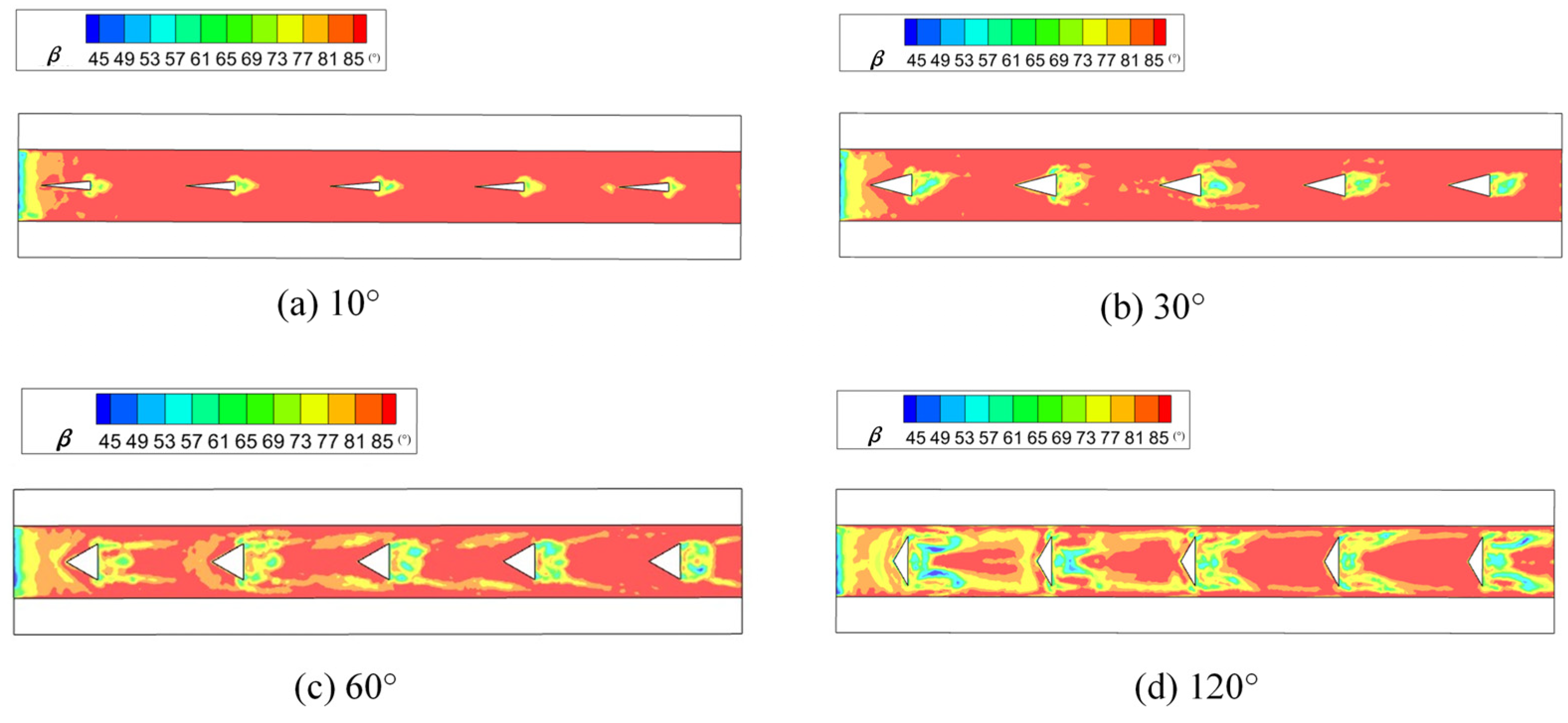
When the top angle of the convex columns was varying from 10° to 150°, the temperature of the inner wall at different angles, the average synergy angle of the cross-section and the pressure drop were simulated (Figure 17). From Figure 17, it can be seen that when the top angle was 120°, the inner wall temperature of the channel was the lowest. Compared with the model before optimization, the temperature is decreased by 0.8 °C, and the average synergy angle decreases by about 1.6°. When the top angle changes from 0° to 110°, the average synergy angle of the cross-section decreases. The angle of the triangle convex column also has a significant effect on the increase in pressure drop. As the angle of the triangular convex column gradually increases from 10° to 130°, the pressure drop also increases. When the angle of the triangle convex column is 120°, the pressure drop increases more than twice as much compared to 60°. This shows that both the shape and angle of the convex column have a significant effect on the pressure drop. When similar methods are used to improve the cooling performance of the spindle cooling channels, consideration of the pressure drop cannot be ignored.
The field synergy effect of the longitudinal cross-section of the cooling channel for four different angles of the convex columns is shown in Figure 18. From Figure 18, it can be seen that when the top angle is 30°, the synergy angle β in most areas of the basin is between 81° and 85°, and when the top angle changes to 60°, 90° and 120°, the synergy angle β decreases significantly.
4. Conclusions
In this paper, by simplifying the spindle cooling channel, the mechanism of the effect of the addition of the convex columns on the fluid velocity field and temperature field is analyzed numerically. Based on the field synergy theory, it is found that building the convex column in the cooling channel can change the fluid velocity vector. With these convex columns, the synergy angle was reduced; thus, the heat transfer and cooling performance of the cooling channel were improved.
The cooling channels with triangular convex columns provided the best cooling effect with the smallest increase in area compared to quadrilateral convex columns and circular convex columns. By optimizing, the distance between the triangular convex columns was set to 7 mm. The average synergy angle of the optimized model decreased by 3.79°, and the average temperature of the inner wall decreased by 1.8 °C. When the heat transfer area was the same, the numerical simulation results showed that the cooling effect of the triangular convex columns with a top angle of 120° was the best. Compared with the regular triangle convex column, the average synergy angle of the optimized columns decreased by 1.6°, and the average inner wall temperature decreased by 0.8 °C.
The effect of different shapes of convex columns on the pressure drop varies greatly with the addition of convex columns in the cooling channels. Compared to the cooling channel without convex columns, the cooling channel with quadrilateral convex columns increased the pressure drop by more than three times and was the highest. The cooling channel with circular convex columns had the smallest increase in the pressure drop but was not as effective as that with triangular and quadrilateral convex columns. Considering the pressure drop data, the triangular convex column is still the rightmost choice when the side lengths are the same. By analyzing the pressure drop data, we conclude that in order to obtain a good cooling effect, it is important to ensure that sufficient pressure drop is provided.
Author Contributions
Formal analysis, W.H.; Methodology, D.S.; Software, J.T.; Supervision, W.Z.; Writing—original draft, Y.L.; Writing—review and editing, Z.N. All authors have read and agreed to the published version of the manuscript.
Funding
This research was funded by the National Natural Science Foundation of China, grant number 52275509; the National Natural Science Foundation of Shaanxi Province, grant number 2022JQ-487; and the Key-Area Research and Development Program of Guangdong Province Grant, grant number 2020B090927002.
Data Availability Statement
Not applicable.
Conflicts of Interest
The authors declare no conflict of interest.
References
- Bryan, J.B. International Status of Thermal Error Research (1990). CIRP Ann. 1990, 39, 645–656. [Google Scholar] [CrossRef]
- Jiao, Y. Study on Thermal Characteristics of New Laminated Cooling Water Jacket for High-Speed Motorized Spindle. Master’s Thesis, Xi’an University of Technology, Xi’an, China, 2020. [Google Scholar]
- Li, Y.; Zhao, W.; Lan, S.; Ni, J.; Wu, W.; Lu, B. A review on spindle thermal error compensation in machine tools. Int. J. Mach. Tools Manuf. 2015, 95, 20–38. [Google Scholar] [CrossRef]
- Li, F.; Gao, J.; Shi, X.; Liang, F.; Zhu, K. Experimental investigation of single loop thermosyphons utilized in motorized spindle shaft cooling. Appl. Therm. Eng. 2018, 134, 229–237. [Google Scholar] [CrossRef]
- Liang, F.; Gao, J.; Xu, L. Investigation on a grinding motorized spindle with miniature-revolving-heat-pipes central cooling structure. Int. Commun. Heat Mass Transf. 2020, 112, 104502. [Google Scholar] [CrossRef]
- Maurya, S.N.; Li, K.-Y.; Luo, W.-J.; Kao, S.-Y. Effect of Coolant Temperature on the Thermal Compensation of a Machine Tool. Machines 2022, 10, 1201. [Google Scholar] [CrossRef]
- Chien, C.H.; Jang, J.Y. 3-D numerical and experimental analysis of a built-in motorized high-speed spindle with helical water cooling channel. Appl. Therm. Eng. 2008, 28, 2327–2336. [Google Scholar] [CrossRef]
- Li, K.-Y.; Luo, W.-J.; Hong, X.-H.; Wei, S.-J.; Tsai, P.-H. Enhancement of Machining Accuracy Utilizing Varied Cooling Oil Volume for Machine Tool Spindle. IEEE Access 2020, 8, 28988–29003. [Google Scholar] [CrossRef]
- Zhang, L.; Liu, T.; Li, C. Research on the Effects of Cooling Water Velocity on Temperature Rise of the Water-cooled Motor in Motorized Spindle. Modul. Mach. Tool Autom. Manuf. Tech. 2015, 25, 583–589. [Google Scholar]
- Wegener, K.; Mayr, J.; Merklein, M.; Behrens, B.A.; Aoyama, T.; Sulitka, M.; Fleischer, J.; Groche, P.; Kaftanoglu, B.; Jochum, N.; et al. Fluid elements in machine tools. CIRP Ann. 2017, 66, 611–634. [Google Scholar] [CrossRef]
- Cheng, Y.; Zhang, X.; Zhang, G.; Jiang, W.; Li, B. Study and Application of Cooling Technology for High Speed Motorized Spindle. J. Harbin Univ. Sci. Technol. 2022, 27, 1–12. [Google Scholar]
- Li, K.-Y.; Luo, W.-J.; Wei, S.-J. Machining Accuracy Enhancement of a Machine Tool by a Cooling Channel Design for a Built-in Spindle. Appl. Sci. 2020, 10, 3991. [Google Scholar] [CrossRef]
- Xia, C. Research on Fast Identification Method for Machine Tool Spindle Temperature Rise Characteristics and a Novel Cooling Structure Design. Ph.D. Thesis, Zhejiang University, Hangzhou, China, 2015. [Google Scholar]
- Deng, X.L.; Pang, S.J.; Li, R.Q.; Zhou, Y.B.; Wang, J.C.; Fu, J.Z. Fluid-Structure Interaction Thermal Design of Cooling Structure for Spindle System Based on Comby Bionic Channel. Comput. Simul. 2020, 37, 183–188. [Google Scholar]
- Deng, X.L.; Pang, S.J.; Li, R.Q.; Zhou, Y.B.; Wang, J.C.; Fu, J.Z. Thermal design of cooling structure for CNC machine tool spindle system based on insect wing vein bionic channel. Chin. J. Eng. Des. 2018, 25, 583–589. [Google Scholar]
- Sleiti, A.K. Heat transfer and pressure drop through rectangular helical ducts. J. Renew. Sustain. Energy 2011, 3, 043119. [Google Scholar] [CrossRef]
- Tang, Y.; Jing, X.; Li, W.; He, Y.; Yao, J. Analysis of influence of different convex structures on cooling effect of rectangular water channel of motorized spindle. Appl. Therm. Eng. 2021, 198, 117478. [Google Scholar] [CrossRef]
- Weber, J.; Shabi, L.; Weber, J. State of the art and optimization of the energy flow in cooling systems of motorized high-speed spindles in machine tools. Procedia CIRP 2018, 67, 81–86. [Google Scholar] [CrossRef]
- Wang, J.; Yu, K.; Ye, M.; Wang, E.; Wang, W.; Sundén, B. Effects of pin fins and vortex generators on thermal performance in a microchannel with Al2O3 nanofluids. Energy 2022, 239, 122606. [Google Scholar] [CrossRef]
- Li, F.; Zhu, W.; He, H. Field synergy analysis on flow and heat transfer characteristics of nanofluid in microchannel with non-uniform cavities configuration. Int. J. Heat Mass Transf. 2019, 144, 118617. [Google Scholar] [CrossRef]
- Yan, Y.; Zhao, T.; He, Z.; Yang, Z.Q.; Zhang, L. Numerical investigation on the characteristics of flow and heat transfer enhancement by micro pin-fin array heat sink with fin-shaped strips. Chem. Eng. Process. Process Intensif. 2021, 160, 108273. [Google Scholar] [CrossRef]
- Bossmanns, B.; Tu, J.F. A thermal model for high speed motorized spindles. Int. J. Mach. Tools Manuf. 1999, 39, 1345–1366. [Google Scholar] [CrossRef]
- Guo, Z. Mechanism and control of convective heat transfer: Coordination of velocity and heat flow fields. Chin. Sci. Bull. 2001, 46, 596–599. [Google Scholar] [CrossRef]
- Guo, Z.Y.; Tao, W.Q.; Shah, R.K. The field synergy (coordination) principle and its applications in enhancing single phase convective heat transfer. Int. J. Heat Mass Transf. 2005, 48, 1797–1807. [Google Scholar] [CrossRef]
- Leng, X.; Zhang, G.; Tian, M.; Cheng, L. Application method of field synergy principle in convective heat transfer. J. Eng. Therm. Energy Power 2009, 24, 352–354. [Google Scholar]
Figure 1.
Motorized spindle structure model.

Figure 2.
Process of model simplification.

Figure 3.
Simplified structure of the model and arrangement of the convex columns.
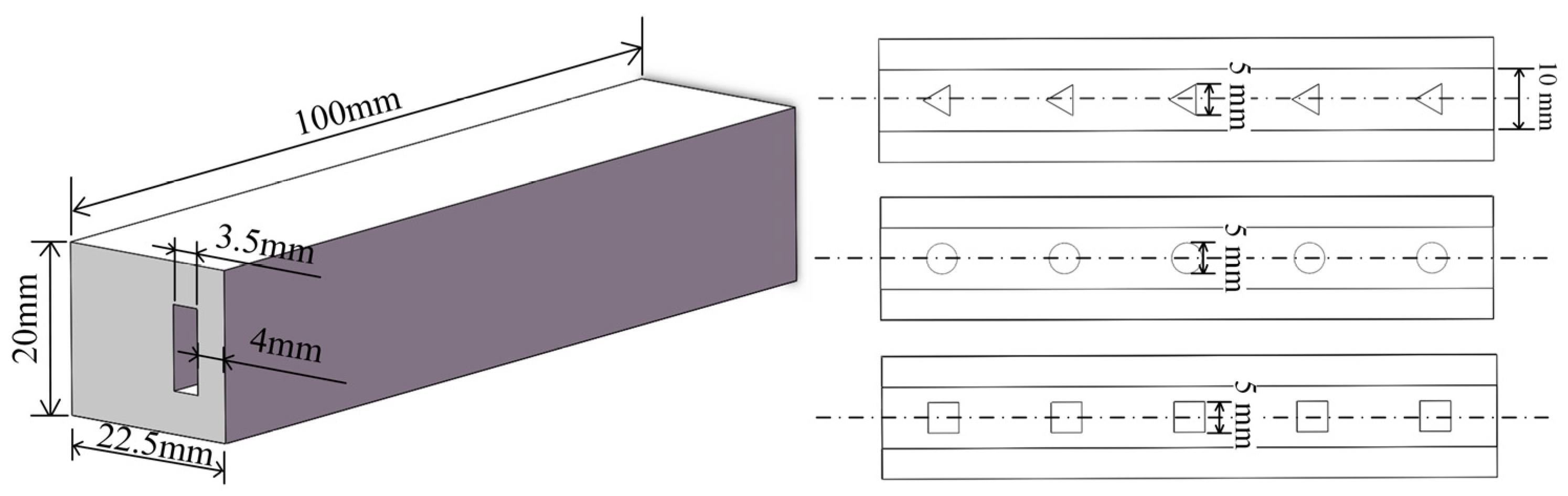
Figure 4.
Mesh model. (a) Model global grid; (b) Boundary refinement grid.

Figure 5.
Grid independence test.
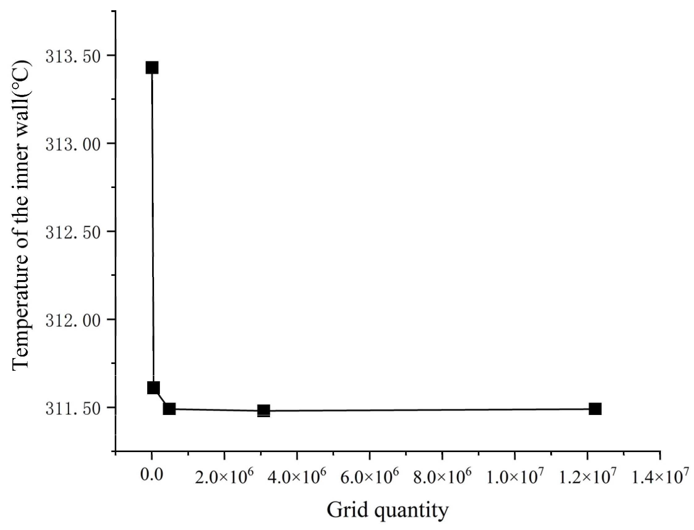
Figure 6.
Flow heat transfer in two-dimensional steady laminar boundary layer.

Figure 7.
Synergistic angle β of different shapes of convex columns.
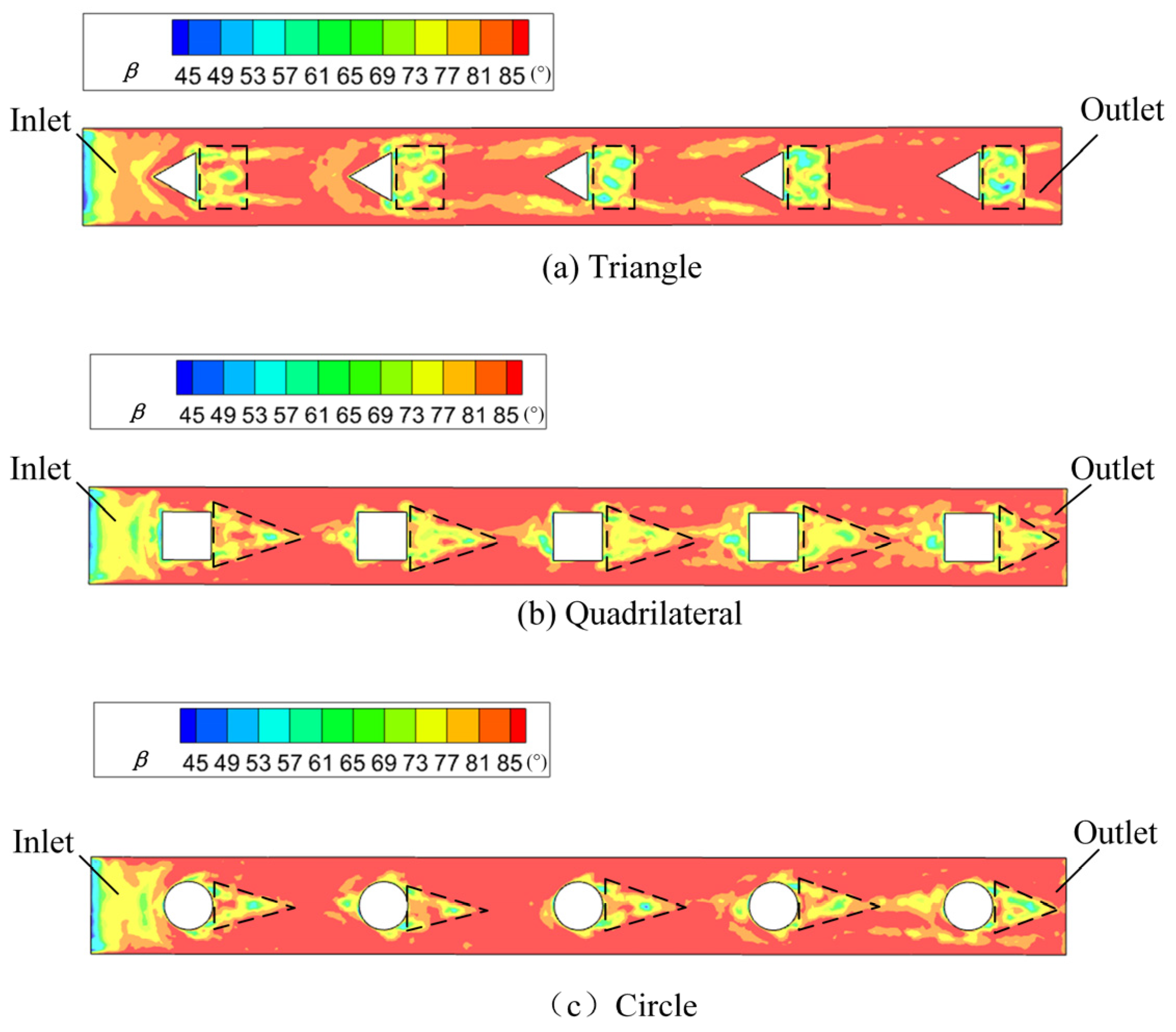
Figure 8.
Temperature field and partial streamline of model with triangular convex.
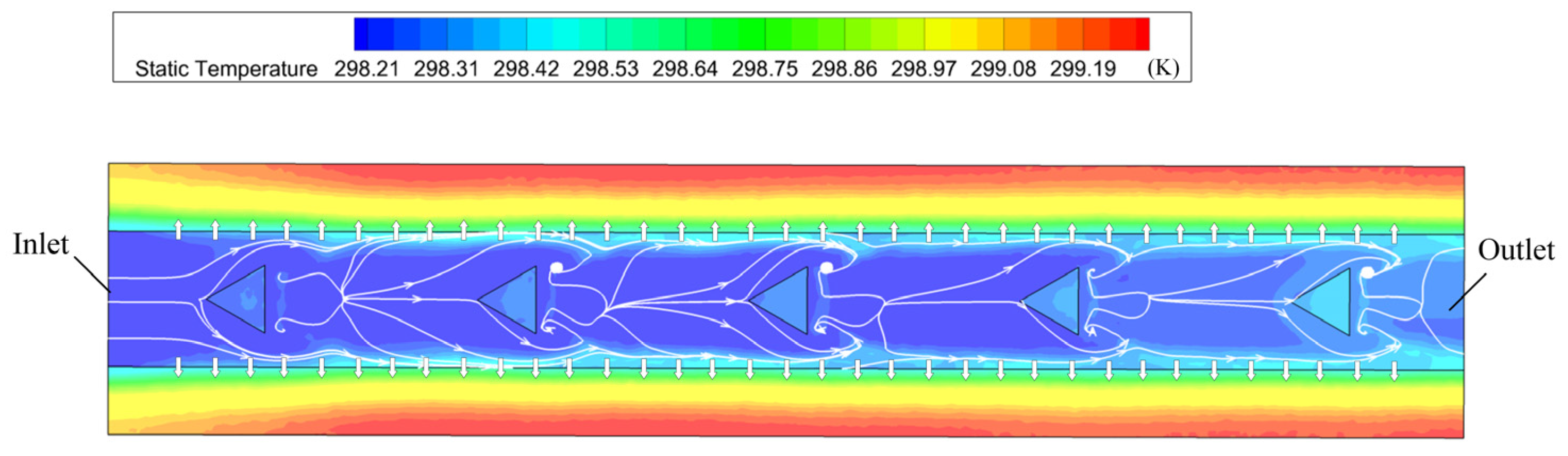
Figure 9.
Average value of the synergy angle β for the 1st–100th cross-sections along the cooling channel.
Figure 9.
Average value of the synergy angle β for the 1st–100th cross-sections along the cooling channel.
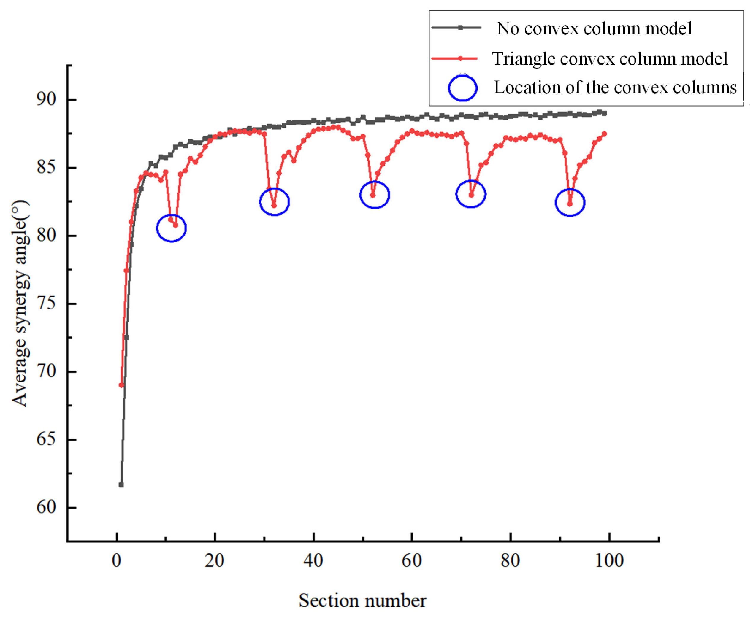
Figure 10.
The average values of β for 100 cross-sections and the temperatures of the inner wall surface at steady state of four different models.
Figure 10.
The average values of β for 100 cross-sections and the temperatures of the inner wall surface at steady state of four different models.

Figure 11.
Pressure drop of different models.
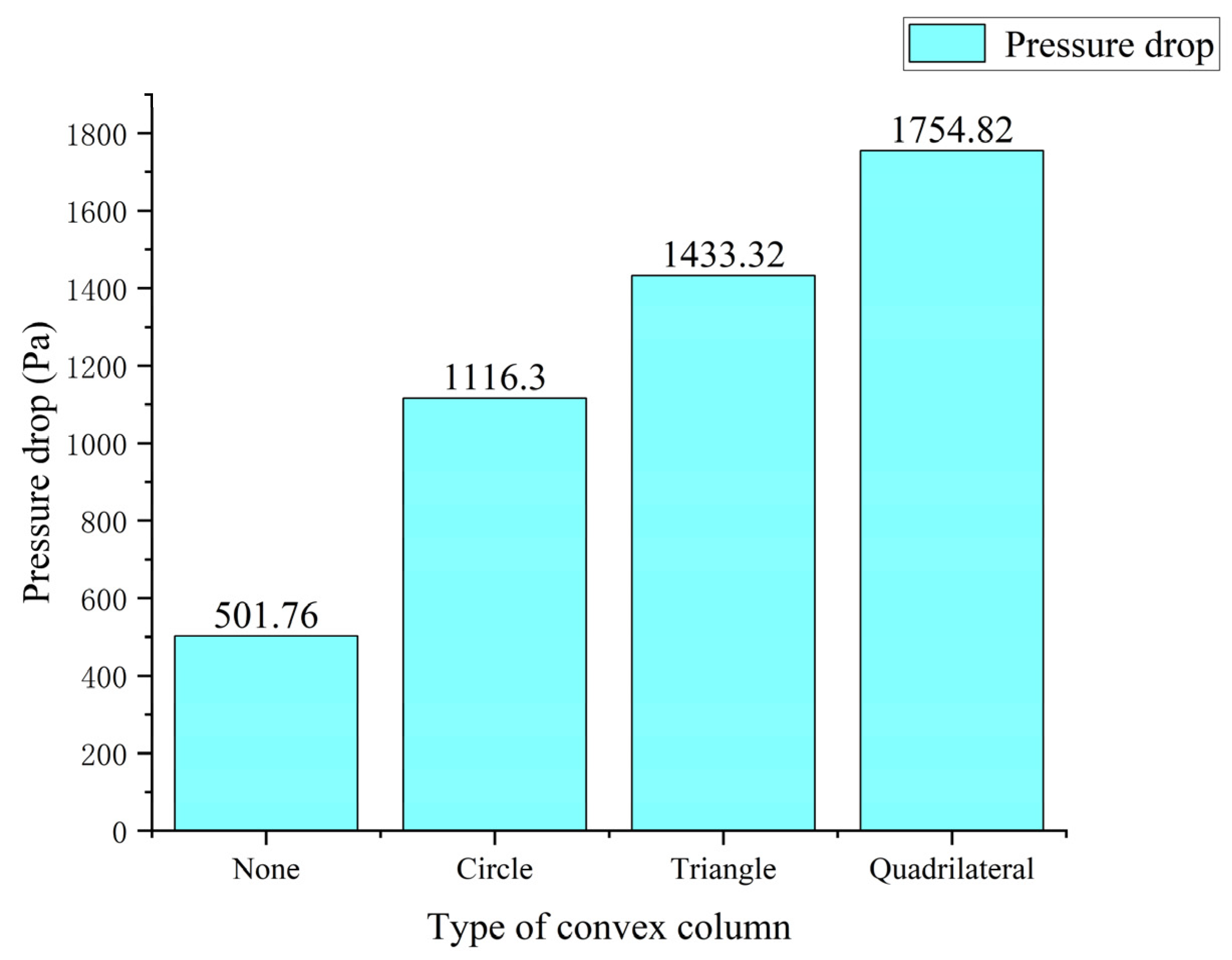
Figure 12.
Mean value of the synergy angle of the section around the convex columns.

Figure 13.
Average inner wall temperature and synergy angle of different cooling channels.

Figure 14.
Synergy angle of cooling channel before and after optimization. (a) Synergy angle of cooling channel before optimization; and (b) Synergy angle of cooling channel after optimization.
Figure 14.
Synergy angle of cooling channel before and after optimization. (a) Synergy angle of cooling channel before optimization; and (b) Synergy angle of cooling channel after optimization.
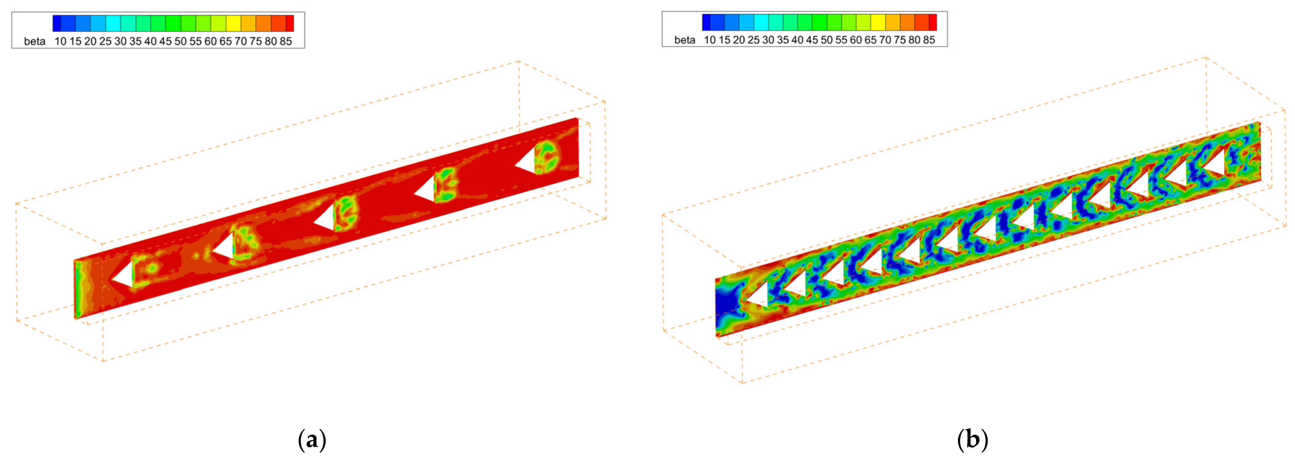
Figure 15.
Average temperature of inner wall of different cooling channels.
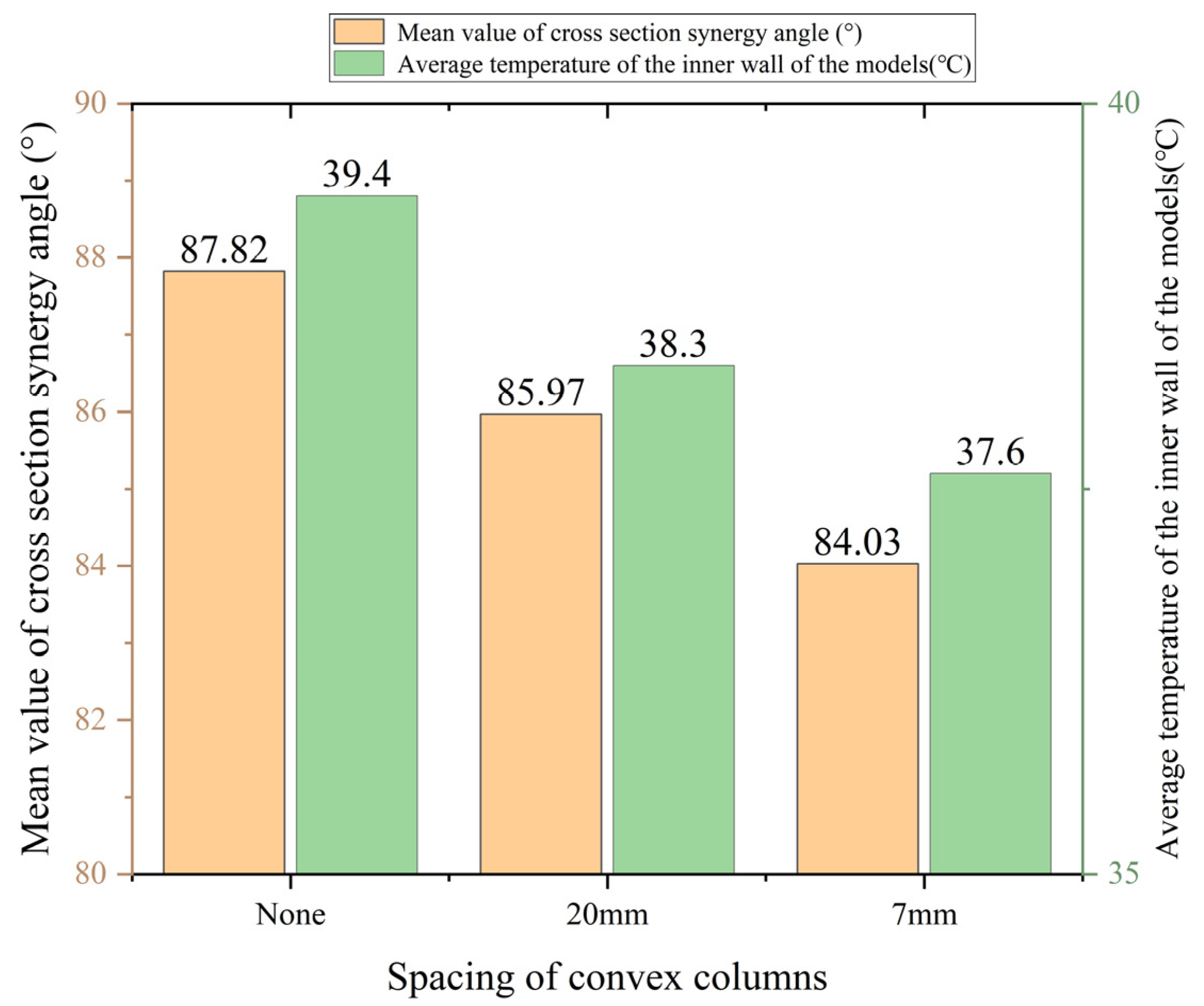
Figure 16.
Pressure drop of different spacing of convex columns.

Figure 17.
Cooling effect and pressure drop of different top angles.

Figure 18.
The cloud image of the longitudinal section of the convex channel with different top angles.
Figure 18.
The cloud image of the longitudinal section of the convex channel with different top angles.

Table 1.
Parameters of the simplified model.
| Channel Parameters | Values |
|---|---|
| Length of the model | 100 mm |
| Width of the model | 22.5 mm |
| Height of the model | 20 mm |
| Distance between the channel and inner wall | 4 mm |
| convex column spacing | 20 mm |
| Width of cooling channel | 3.5 mm |
| Height of cooling channel | 10 mm |
| Height of convex columns | 1.5 mm |
| Length/Diameter of the side of the convex column | 5 mm |
| Number of convex columns | 5 |
Table 2.
The parameters of steel.
| Parameters of Steel | Values |
|---|---|
| density | 8030 kg/m3 |
| specific heat capacity | 502.48 J/(kg·K) |
| heat conductivity | 16.27 W/(m·K) |
Table 3.
The values of the main parameters.
| Main Parameters | Values |
|---|---|
| inlet velocity | 1 m/s |
| inlet temperature | 298.15 K (25 °C) |
| outlet pressure | 0 Pa (Gage pressure) |
| environment temperature | 298.15 K (25 °C) |
| inner surface heat flux | 30,000 W/m2 |
| natural convection heat transfer | 9.7 W/(m2·K) |
Table 4.
Increased heat transfer area of different shapes of the convex column.
| Shape of the Convex Column | Increased Heat Transfer Area (mm2) |
|---|---|
| triangle | 112.5 |
| quadrilateral | 150 |
| circle | 117.81 |
Disclaimer/Publisher’s Note: The statements, opinions and data contained in all publications are solely those of the individual author(s) and contributor(s) and not of MDPI and/or the editor(s). MDPI and/or the editor(s) disclaim responsibility for any injury to people or property resulting from any ideas, methods, instructions or products referred to in the content. |
© 2023 by the authors. Licensee MDPI, Basel, Switzerland. This article is an open access article distributed under the terms and conditions of the Creative Commons Attribution (CC BY) license (https://creativecommons.org/licenses/by/4.0/).
Share and Cite
MDPI and ACS Style
Li, Y.; Nie, Z.; Su, D.; Tian, J.; He, W.; Zhao, W. Study on Enhanced Heat Transfer of the Convex Columns in the Cooling Channel of Motorized Spindle Based on Field Synergy. Processes 2023, 11, 2431. https://doi.org/10.3390/pr11082431
AMA Style
Li Y, Nie Z, Su D, Tian J, He W, Zhao W. Study on Enhanced Heat Transfer of the Convex Columns in the Cooling Channel of Motorized Spindle Based on Field Synergy. Processes. 2023; 11(8):2431. https://doi.org/10.3390/pr11082431
Chicago/Turabian StyleLi, Yang, Zhe Nie, Dongxu Su, Jingyao Tian, Wenlei He, and Wanhua Zhao. 2023. "Study on Enhanced Heat Transfer of the Convex Columns in the Cooling Channel of Motorized Spindle Based on Field Synergy" Processes 11, no. 8: 2431. https://doi.org/10.3390/pr11082431
Note that from the first issue of 2016, this journal uses article numbers instead of page numbers. See further details here.