Article

Enhancing Electric Discharge Machining Performance by Selecting Electrode Design and Geometrical Parameters for Square, Triangular, and Hexagonal Profiled Holes

1
Department of Industrial and Manufacturing Engineering, University of Engineering and Technology, Lahore 54890, Pakistan
2
Department of Industrial Engineering, College of Engineering and Architecture, Al Yamamah University, Riyadh 11512, Saudi Arabia
3
Department of Industrial Engineering, College of Engineering, King Saud University, P.O. Box 800, Riyadh 11421, Saudi Arabia
*
Author to whom correspondence should be addressed.
Processes 2023, 11(9), 2661; https://doi.org/10.3390/pr11092661
Submission received: 6 August 2023 / Revised: 23 August 2023 / Accepted: 28 August 2023 / Published: 5 September 2023
(This article belongs to the Special Issue High-Performance Machining Processes: From Mechanisms to Equipment)

Abstract

:
Manufacturing of dies, molds, and their allied components requires the machining of holes with different profiles. Electric discharge machining (EDM) die-sinking is a crucial process used in the dies and molds manufacturing industry. By nature, EDM die-sinking is a relatively slow process in terms of material removal rate (MRR) and there are high amounts of tool material loss in terms of tool wear rate (TWR) which directly influence dimensional accuracies and surface roughness (SR). Therefore, the process is continuously evolving to address these limitations. The present research is aligned in this direction such as to bring improvements in MRR, TWR, and SR through modifications to the conventional electrode design and its geometrical parameters. Traditional designs of EDM electrodes have a uniform cross-section through the tool’s entire length and have only one geometrical parameter, i.e., the tool’s cross-section. To improve the EDM performance, traditional designs are completely modified by introducing several geometrical parameters such as relief angles, land thickness, cross-sectional area, shank height, circular relief, and non-circular relief, etc. Electrode designs are employed to mill non-circular profiles including triangular, square, and hexagonal shaped holes. The EDM performance measures strongly depend on the tool’s geometrical parameters (design type, relief angle, land thickness), machining profile (circular, square, triangle, hexagon), as well as the height/depth of the machining feature. By selecting proper tool designs and corresponding geometrical parameters, the EDM performance measures can be improved significantly.

1. Introduction

AISI D2 steel is used in many applications, especially in the manufacturing of dies and molds that require increased hardness, toughness, wear, and abrasion resistance. D2 steel and its family materials are widely used in various types of dies and molds such as cold stamping dies, punching dies, drawing and extrusion dies, high-pressure die casting molds, and several types of engineering tooling such as cutting tools (tool inserts), shear blades, cutting blades, and high-wear parts [1]. Owing to its high wear resistance, D2 steel performs better than other materials in deep drawing dies [2]. These applications and other industry needs often require the machining of AISI D2 steel [3]. Conventional machining of the aforesaid material is reported as difficult and challenging due to significant wear and catastrophic tool failure, especially during the conventional machining processes such as turning and milling. Electric discharge machining (EDM) is among the old non-conventional machining processes [4]. For this process, numerous researchers have studied the material removal rate (MRR), tool wear rate (TWR), surface roughness (SR), and dimensional correctness of the machined features [5]. By nature of the machining mechanism, EDM is a slow machining process. The primary goal in EDM die-sinking is to achieve a high MRR [6]. Researchers have been working to enhance the MRR by minimizing the EDM machining time through researching different approaches and modifications in the process parameters. Excessive erosion and loss of the electrode material frequently directly induces dimensional inaccuracies in the machined features. Excessive tool wear also requires the replacement of the electrode with a new one and new electrode fabrication is a challenging and time-consuming task which leads to higher machining costs.
However, to improve EDM performance measures, the use of different types of dielectrics instead of using conventional kerosene oil is desirable. The addition of micro and nano powders in the dielectric fluid is another extension. This is called powdered mixed EDM (PMEDM) which is one of the popular methods being practiced in EDM die-sinking. Similarly, the type of dielectric fluid results in the direct impact on EDM performance, particularly in terms of MRR, SR, and TWR. This is evident because dielectric fluid shares heat energy from electric discharges. Researchers also adopted particles of ceramic composites such as Al2O3 and Si3N4 mixed in the dielectric medium [7]. Others increase MRR and decrease TWR-employed additives surfactant and aluminum powder [8], nano-powder mixed with dielectric [9], and powder mixed EDM on tool steel [10]. Powder-mixed EDM and standard EDM were compared for tool steel material removal [11].
Another area of research to explore the influence of tool material over the performance metrics of EDM die-sinking is the use of diverse electrode materials. Depending on the kind of electrode material used in EDM, the rate of material erosion varies. It is essential to select an adequate and suitable electrode material to increase the rate of material removal. For example, Klocke et al. [12] used the graphite electrode to investigate the MRR and TWR. In the same way, Younis et al. [13] determined the efficiency of EDM through two distinct graphite electrodes in terms of SR. Valaki et al. [6] claimed that engaging the graphite electrode in EDM with the positive polarity was the suitable choice for getting a least dimensional error compared to the negative polarity.
In-depth studies have been conducted to determine how EDM process variables impact EDM performance. For example, the electrode polarity and spark voltage significantly contribute to increasing the material removal rate [14]. It is critical to take process parameter variability, such as discharge peak current and pulse duration, into account when determining the causes and effects of MRR and TWR [15]. Discharge energy during base material cutting is influenced by EDM process variables as well. The size and radius of craters are impacted by discharge energy changes during experiments. Surface roughness (SR) and MRR are impacted [15]. Moreover, it is evident that discharge current and pulse duration affect machined surface roughness [16]. It is also evident that the inter-electrode spacing affects MRR and SR [17,18]; they monitored spark activity, MRR, and surface finish during EDM by utilizing acoustic emission signals. In another study, Sharma et al. [19] used nickel-based super-alloys to evaluate EDM performance by employing different types of machining parameters and proposed the optimized combination of process parameters. Similarly, Shyn et al. [20] used a metal matrix composite in their study to investigate MRR, SR, and TWR, and claimed an improvement of 0.167%, 9.31%, and 2.61%, respectively.
Another strategy to overcome the EDM’s restrictions is to provide rotation to the tool electrode. For example, Phang et al. [21] engaged the electric discharge turning (EDT) to evaluate the SR of a workpiece during the machining process by utilizing the jump down time, electrode shape and rotational speed of the workpiece as process parameters. They claimed that the electrode’s shape and the rotational speed of the workpiece are the most effected parameters to improve SR; however, the remaining parameter had a least influence on the SR. Another one of the main drawbacks of EDM is the re-sticking of melt debris. The provision of tool rotation can reduce the amount of debris sticking to the work surface as reported by Chou et al. [22]. Yadav et al. [23] assessed the effectiveness of EDM by including oxygen into the dielectric and by utilizing the rotary electrode. They found an improvement in MRR; however, the issue with the recast layer thickness and hole overcut increased enormously. They observed sticking of melt debris is more severe in the event if deep holes are being machined through EDM. They noted inefficient flushing during deep hole EDM is the major cause of re-deposition of melt debris. On other hand, according to Cui and Chu’s [24] investigation the melt debris builds up in the partially drilled hole and solidifies with the inside walls of the hole. One of the methods that is frequently utilized to enhance the machining process as well as the accuracy of the features is an optimization of the process parameters [25,26]. For instance, Kumar et al. [27] optimized the EDM’s parameters for aluminum boride composite, and Singh et al. [28] conducted multi-response optimization in order to negotiate with tungsten carbide samples. Both studies dealt with the optimization of machining processes. In a similar manner, multi-objective optimization of EDM process parameters was attempted in another study to mill titanium alloy [29]. This work followed a similar line of thought to the previous one.
Thus, the literature studied reveals that researchers working on various aspects of EDM die-sinking gives most importance to MRR improvements and keeps objectives to minimize tool wear and surface roughness using conventional electrode shapes such as circular or rectangular electrodes. It is suggested to have a new method of improving the EDM performance measures, and this needs the modifications in EDM electrode designs and its allied parameters. For example, Ahmad Mufti et al. [30] used various types of shapes of electrodes in EDM by giving the relief angles, and concluded that modified shapes of electrodes with relief angles enhanced the EDM’s performance and reduced the machining time while producing circular holes in tungsten carbide. This method of EDM process improvement has been introduced in very recent years and is being explored further. The present research falls along a similar line of direction but for machining non-circular holes profiles.
As a research gap, there is potential to significantly contribute to the EDM knowledge base. Particularly in the tool and die industry, relief-angled-based tools are used to generate square, triangular, and hexagonal forms for enhanced machining. These tools are used to create various intricate shapes (through-holes) on the workpiece surface. Their performance is on par with that of traditional tools, which have a cross-section that is constant over their whole length. Therefore, here in the presented study, different process parameters such as two electrode designs, i.e., conventional design without any relief angle (C0) and circular relief angled design with land (CRL), two relief angles (20° and 40°), three-hole shapes (square, triangular, and hexagonal), varying workpiece thickness (4 mm, 6 mm, and 8 mm), and varying land height (2 mm, 3 mm, and 4 mm) were utilized to measure the MRR, TWR, and SR. The use of varying magnitudes of process parameters have proven significant improvement in the EDM performance measures. Surface topographic in-depth analysis of the tool surface and workpiece machined surface has been performed to investigate the effects of tool design parameters on the surface characteristics of the tool and workpiece. Subsequently, multi-objective optimization has been performed and an appropriate setting suggested to improve performance measures. The industrial sector, particularly the dies and mold producing industry, directly benefits from the experimental findings and investigation presented herewith.

2. Materials and Methods

There is a vast use of die steels, such as AISI D2, in the die and tool production sectors [1]. For example, stamping dies are made up of several materials; however, D2 steel is one of the preferred choices since D2 offers high impact toughness [31]. Therefore, considering the wide range of applications of D2 steel, it was taken as the workpiece material. Red copper is among the most common electrode materials used in die sinking EDM. The suitable combination of tool electrode and workpiece electrode material is very important in EDM. Copper was selected as the material of tool electrode in this research since it has proven better machining results while machining D2 steel [32,33]. Material removal rate (MRR), tool wear rate (TWR), surface roughness (SR), and dimensional correctness of machined features are considered as important performance measures in EDM die-sinking [5,34]. Therefore, material removal rate (MRR), tool wear rate (TWR), and surface roughness (SR) were opted as the response measures in the present study. EDM die-sinking is a type of electrical energy-based process where the influence of many electric sparks erodes the substrate and the electrode. A dielectric fluid made of kerosene oil was utilized, and the substrate was entirely submerged in it, so tha t the machining process and the flushing of vaporized material could be completed. Table 1 provides the chemical composition and some physical and mechanical properties of the work material.
As a workpiece, the selection of three different sized blocks of AISI D2 steel with thicknesses of 4 mm, 6 mm, and 8 mm, respectively, have been prepared through cutting and grinding. Regarding the workpiece’s preparation, numerous blocks were cut using WEDM to the length, width, and thicknesses of a rectangular plate with the aforementioned thicknesses and dimensions of 152.4 mm and 76.2 mm, respectively. The machined profiles consist of three cross-sectional types of through-holes which include square, triangular, and hexagonal cross-sections. The traditional way to create non-circular holes is to use an electrode that has a constant cross-section over its whole length. This method has been around for quite some time. For instance, as can be seen in Figure 1, the cross-section of a square, triangular, or hexagonal tool is constant all the way down its length; however, land height is varied to 2 mm, 3 mm, and 4 mm. During this investigation, two electrode designs of tools (conventional design (C0) and circular relief design (CRL)) have been altered by the incorporation of the relief angles 0° (conventional design), 20° (square and triangle), and 40° (hexagonal shape), as seen in Figure 1. The selection of these relief angles is based on an extensive preliminary experimentation and the previous study presented in [38]. Table 2 highlighted the design parameters used in this research. However, the EDM’s constant parameters are presented in Table 3. The tools required to perform operations need a tremendous amount of precision and focus at every stage. To ensure uniformity in production and to eliminate any impact of tool material on machining performance, all tools were manufactured using the same copper rod. Table 3, below, presents the characteristics of the tool design.
Adopted MRR, TWR, and SR as the performance characteristics of EDM. Data gathering and measurements pertaining to the aforementioned measures were performed with great care. The weighing technique of measurement was used to compute the MRR and TWR. The workpiece and the tools’ pre-cut and post-cut weights were recorded using a digital weighing scale with a 1 g weighing resolution. D2 steel’s density and machining time were divided by the weight difference to obtain MRR. The density was determined using the g/cm3 unit. Similar calculations were made for TWR. The density of copper (8.96 g/cm3) was used in the calculations for tool wear rate. The MRR computation is shown below in the form of Equation (1). SR measurements were performed using a Surtronic Taylor Hobson surface roughness meter. A 3 mm evaluation length was employed to gauge roughness. The minimal work thickness was 4 mm and three different plates of various size (4 mm, 6 mm, and 8 mm) were employed as the workpiece. In order to have a through-hole of 4 mm thickness and measuring its surface roughness, the available surface length was 4 mm. Therefore, a 3 mm evaluation length was selected to record the surface roughness values. To keep the workpiece firmly in place and guarantee the accuracy of each measurement, a fixture was created. Average Ra values are reported based on three-point readings. Microscopic analysis of the machined surface and electrode surface was carried out using USB Digital Microscope (50×–1500×).
M R R = W D 2 ρ D 2 × T m           Or         M R R = V m T m
where
W D 2 = W b e f o r e   m a c h i n i n g W a f t e r   m a c h i n i n g
ρ D 2 = D e n s i t y   o f   D 2   s t e e l
V m = v o l u m e   o f   m a t e r i a l   r e m o v e d   ( μ m 3 )
V m = W D 2 ρ D 2
T m = M a c h i n i n g   t i m e
Equation (2) represents the formula for TWR.
T W R = W C u ρ C u × T m           Or           T W R = V m T m
where
W C u = W b e f o r e   m a c h i n i n g W a f t e r   m a c h i n i n g
ρ C u = D e n s i t y   o f   C o p p e r
V m = v o l u m e   o f   m a t e r i a l   r e m o v e d   ( μ m 3 )
V m = W C u ρ C u
T m = M a c h i n i n g   t i m e

3. Results and Discussion

The MRR, TWR, and SR have been investigated utilizing the separate process parameters of workpiece thickness and land thickness to assess machining supremacy. In Table 4, the findings of the response measures are presented. Microscopic images have been used to describe the process physics, and in order to obtain the best process parameter setting, multi-objective optimization is preferred.

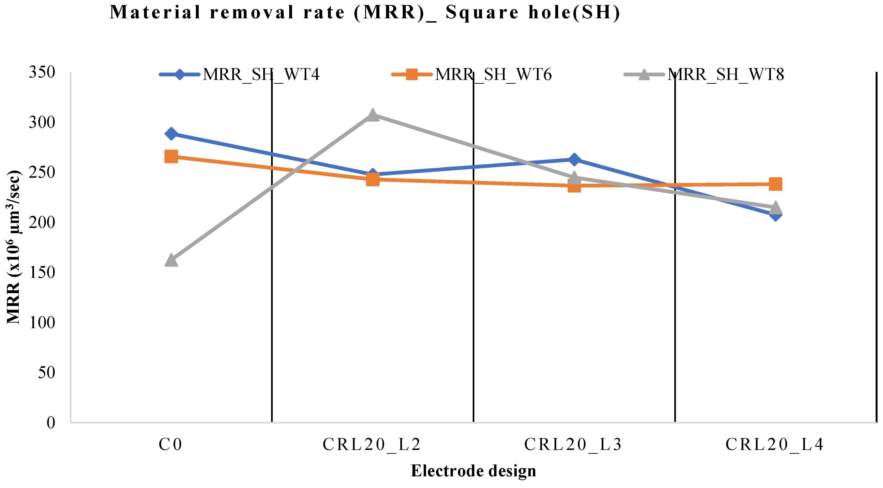
3.1. Parametric Effects on Material Removal Rate

The machining performance of EDM has been investigated in terms of MRR by engaging the variable workpiece thickness against the C0 and CRL electrodes. From Figure 2, it is found that the conventional electrode gave the highest MRR when the workpiece thickness of 4 mm was used to produce a square hole. It was mentioned earlier that the through-holes were produced in the workpiece material instead of blind holes. Therefore, to make a through-hole in workpiece material the conventional Cu electrode encounter with minimum thickness and high conductivity of a Cu electrode produced a greater spark and erodes higher material from the workpiece material. However, when CRL20 and a land thickness of 2 mm were used for the machining of D2-grade, then a workpiece thickness of 8 mm gave the highest value of MRR compared to the other combinations of tool designs and workpiece thicknesses. The primary reason is that no irregular sparking was noticed during the machining process which leads to the uniform cutting process and hence high MRR was achieved. The schematic of the sparking processes during EDM with typical and unconventional electrode configurations is shown in Figure 3. It is clear that the C0 design generates a plasma area that is both broader and deeper than the CRL design. In the case of the typical C0 design, the tool increasingly tended to penetrate lengthwise inside the machined depth as the machined hole’s profile proceeded and a certain depth was reached. At this point, there was a bigger surface area that could produce sparks. The side surface around the tool’s perimeter produced electric sparks with the side walls of the machined hole in addition to the tool’s footing face. Side sparking or peripheral sparking are terms used to describe the phenomena. The tool’s bottom surface area stayed consistent throughout the machining process. Nevertheless, because of the homogenous cross-section of the tool, as the cutting depth was increased, the tool’s surface area increased around the perimeter. As a result, there was more side sparking, which caused the plasma zone in Figure 3 to be larger and deeper. At the beginning of the machining, the CRL electrode design’s sparking behavior was the same as that of conventional designs. The sparking behavior changed as the machining depth was raised. Starting with the uppermost layer of the work surface (bottom surface and peripheral surface), the surface area for dazzling increased up to a machining depth of 1 mm. The increase in total surface area (bottom and perimeter) peaked once a machining depth of 1 mm was attained. The tool’s sidewalls were straight for 1 mm and subsequently tapered due to the presence of the relief angle, so the sparking surface area remained constant as the depth climbed. Additionally, it was noted that while side sparking increased progressively when the C0 tool design was used, it remained constant when relief angles were added to the tool design. As a result, a plasma region formed along the land’s surface. As the land thickness varies, the plasma region alters due to the spark’s intensity. At low land thickness, the high intensity sparks generate due to less hindrance for the flow of electrons which cause a high material removal rate and reverse behavior occurred at high land thickness as depicted in Figure 3. Further, a land thickness of 3 mm and 4 mm gave the minimum erosion of material from the workpiece material compared to 2 mm land thickness. The reason is that at 2 mm land thickness, there was less resistance for the flow of electrons and hence produced greater spark density to erode the material. However, in the case of 3 mm or 4 mm, land thickness hindrance for the flow of electrons was much more which impedes the MRR.
The machining proficiency of EDM has been investigated by engaging a triangular Cu electrode with varying land and workpiece thicknesses for the machining of D2-grade. From Figure 4, it is clear that when a workpiece thickness of 4 mm and conventional Cu electrode are engaged for the EDM of D2-grade, it gave a high MRR. The high thermal conductivity of the Cu electrode did not allow the heat to become trapped and let it go immediately. Therefore, the greater amount of material is eroded from the least workpiece thickness, and results in the high MRR compared to the other two workpiece thicknesses where a larger amount of material is encountered with the Cu electrode. When a land thickness of 2 mm is employed, again due to the least thickness of the workpiece, a high MRR was achieved compared to other combinations of land and workpiece thicknesses. The basic reason for the high MRR is associated with the triangular geometry of Cu electrodes due to the area of sparking increasing and a high erosion of material taking place. However, when a land thickness of 3 mm and 4 mm were engaged against the workpiece thickness of 6 mm and 8 mm then MRR was reduced. The depreciation in MRR is due to a high workpiece thickness where the electrode took greater time to make a through-hole and results in the reduction of MRR.
The MRR was also determined by engaging the conventional and hexagonal Cu electrode for the EDM of D2-grade (refer Figure 5). From Figure 5, it is evident that when a workpiece thickness of 4 mm was used against the conventional and hexagonal electrode with various land thicknesses, it gave high MRR in all combinations. The hexagonal Cu electrode with a 2 mm land thickness gave high MRR compared to the conventional Cu electrode. This is because the hexagonal shape has six corners and due to this an extensive spark was produced which melts and vaporizes the larger material and results in high MRR. If a land thickness of 3 mm is engaged with 6 mm thickness of workpiece, then it is favored in reduction of MRR. All of this arose as a result of the workpiece’s thickness increasing, which made drilling a through-hole time-consuming and decreased MRR. However, compared to the prior scenario, the MRR increased with a workpiece thickness of 8 mm and a land thickness of 4 mm. This occurs as a result of the high intensity heat generated, which melts and erodes the material of the workpiece.
If a comparison is performed among the different situations given above, then it is found that maximum MRR (317.24 × 106 μm3/s) was achieved by engaging the hexagonal copper electrode with minimum land and workpiece thicknesses. The percent increase in MRR achieved owing to square and triangular Cu electrodes, respectively, is 3.2% and 26.08% better than the magnitude of MRR due to the hexagonal Cu electrode.

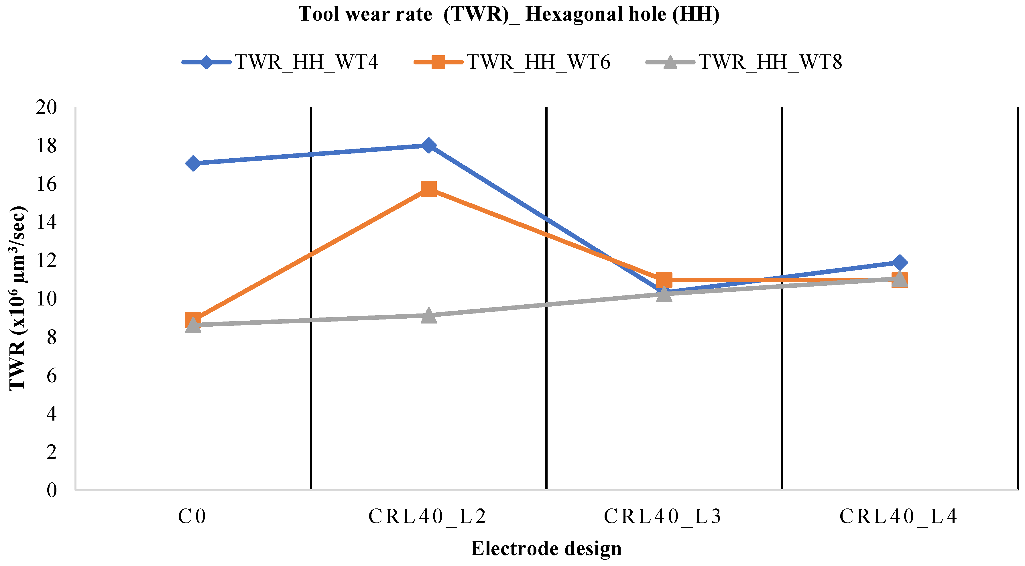
3.2. Parametric Effects on Tool Wear Rate

The effect of tool wear rate has also been evaluated by employing the different electrode designs and various workpiece thickness. The least thickness of the workpiece gave the highest TWR as shown in Figure 6. The reason is that the discharge heat produced during the plasma generation also erodes the electrode material which results in high TWR. When the thickness of workpiece increased, the conventional square Cu electrode tends to give the least TWR. The microscopic image shown in Figure 7a illustrates the high TWR while the 3D profilometry also indicates the peaks which is the indication of deep craters. However, when a Cu electrode with a land thickness 2 mm was employed to machine the D2-grade, then it is clear that the workpiece thickness of 6 mm is in favor of the small TWR compared to other options. Moreover, the TWR obtained by the utilization of a Cu electrode with a land thickness of 4 mm is comparatively small as compared to a conventional Cu electrode. Figure 7b indicates the lesser erosion of the Cu electrode; in addition to that, 3D profilometry also depicts the shallow craters. The TWR obtained by the square Cu electrode with a land thickness of 4 mm is the least and presented in the form of a micrograph as shown in Figure 7c. The 3D profilometry indicates shallow craters which is the illustration of less erosion of the Cu electrode.
The TWR was also investigated by employing the different designs of a triangular Cu electrode against the D2-grade in the EDM (refer to Figure 8). Figure 8 shows that maximum TWR was obtained when a workpiece with a thickness of 4 mm was used in conjunction with various designs of a triangular Cu electrode. The reason for this is associated with plasma channel generation which also melts and vaporizes the Cu electrode and results in high TWR. The micrograph shown in Figure 9a indicates the smallest TWR obtained when an 8 mm workpiece thickness was engaged for the EDM of D2. When a workpiece thickness of 6 mm was used against the triangular Cu electrode, it ranked second in giving the least TWR throughout the possible combinations of electrode designs. The TWR obtained by engaging the workpiece thickness of 8 mm was the least for a triangular Cu electrode in all combinations of electrode designs. The microscopic image shown in Figure 9b,c depicts the better surface profilometry which is the indication of improved machined surfaces.
The EDM of D2 has also been determined in terms of the TWR of a hexagonal Cu electrode using various electrode designs as shown in Figure 10. When a conventional Cu electrode is used against the workpiece thickness of 4 mm, then it gave the highest TWR. The high TWR was due to discharge heat produced during the spark on time, and some part of the discharge heat also transferred to the electrode material and results in the erosion of the Cu electrode. However, when the workpiece thickness of 6 mm or 8 mm engaged with a conventional electrode then depreciation in TWR was found. Figure 11a depicts the microscopic and 3D profilometry images of a machined electrode where irregular asperities were formed and indicates the high TWR. When a land thickness of 2 mm was employed with a Cu electrode then, again, a high TWR was found with the 4 mm thickness of workpiece, and an 8 mm workpiece thickness gave the least TWR. However, when a land thickness of 3 mm and 4 mm were used against the workpiece thickness of 6 mm and 8 mm, then increments in TWR were found compared to the 2 mm land thickness. The microscopic image shown in Figure 11b,c tends to depict the poorer surface finish.
The least TWR was found to be 3.87 × 10⁶ m3/s when a square Cu electrode with 2 mm land thickness was utilized against the 6 mm workpiece thickness, according to a study of the various TWRs achieved by various electrode designs for the EDM of D2. The maximum magnitude of TWR recorded in triangular and hexagonal Cu electrodes, respectively, was 62.93% and 122.99%.

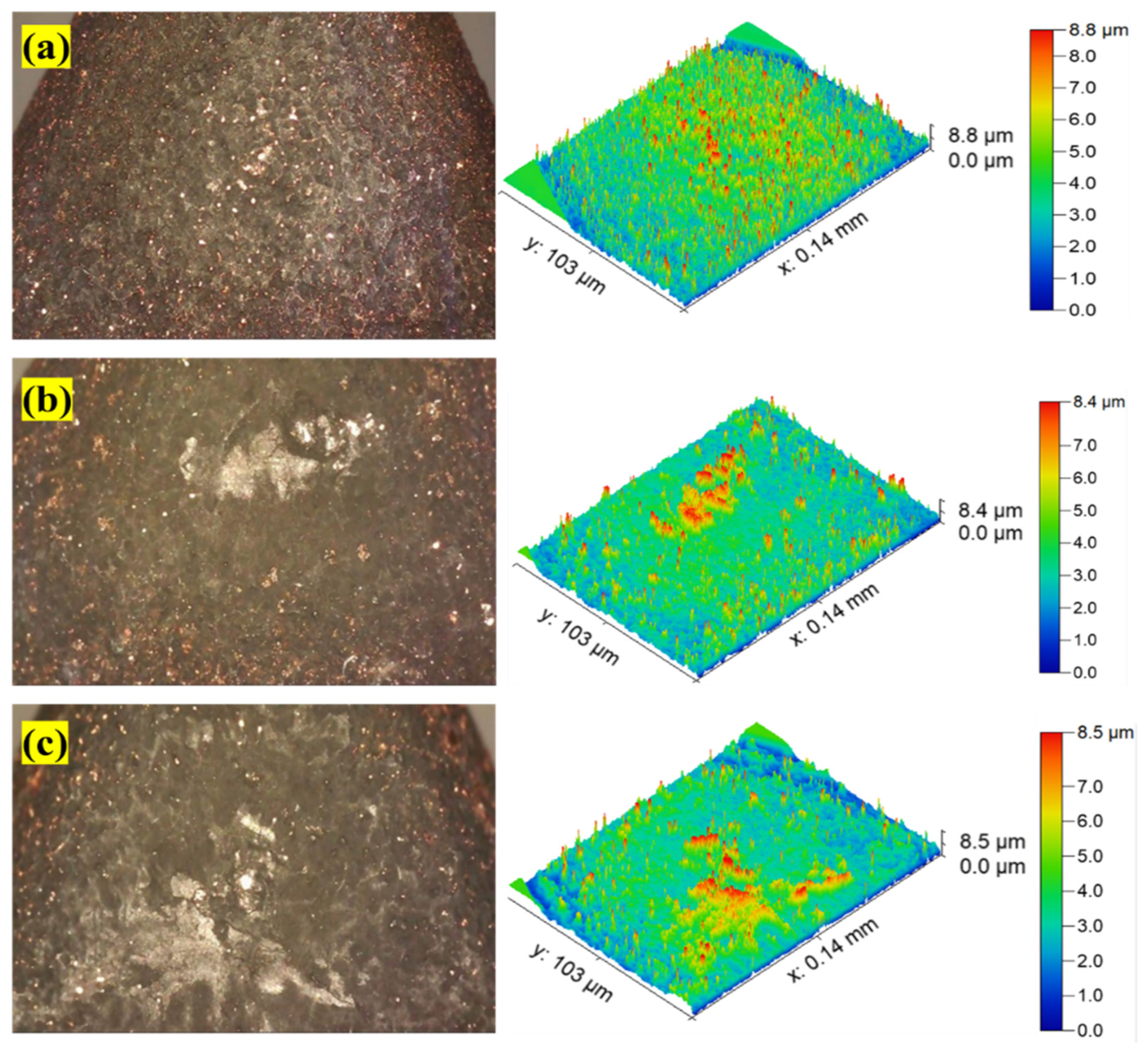
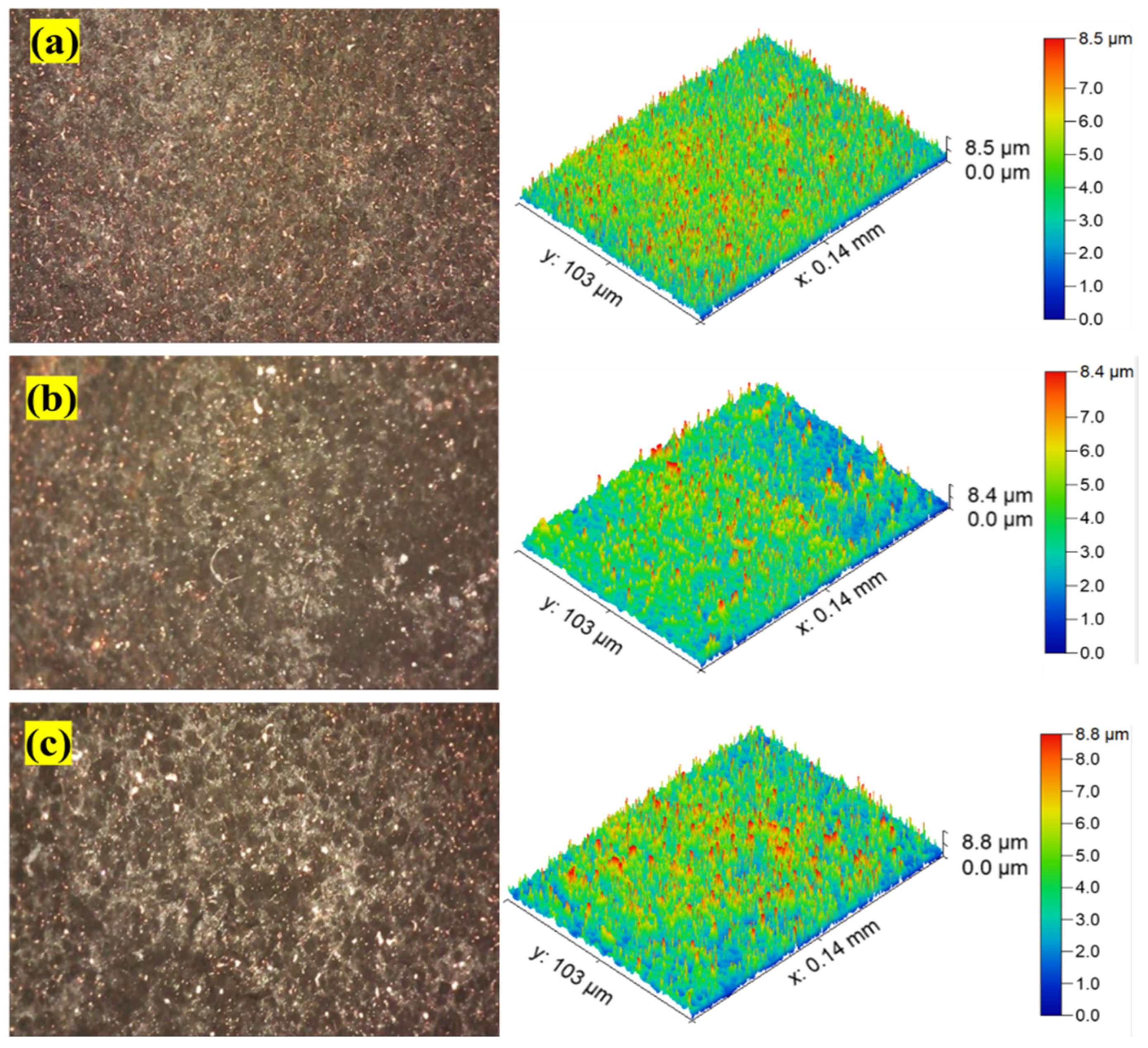
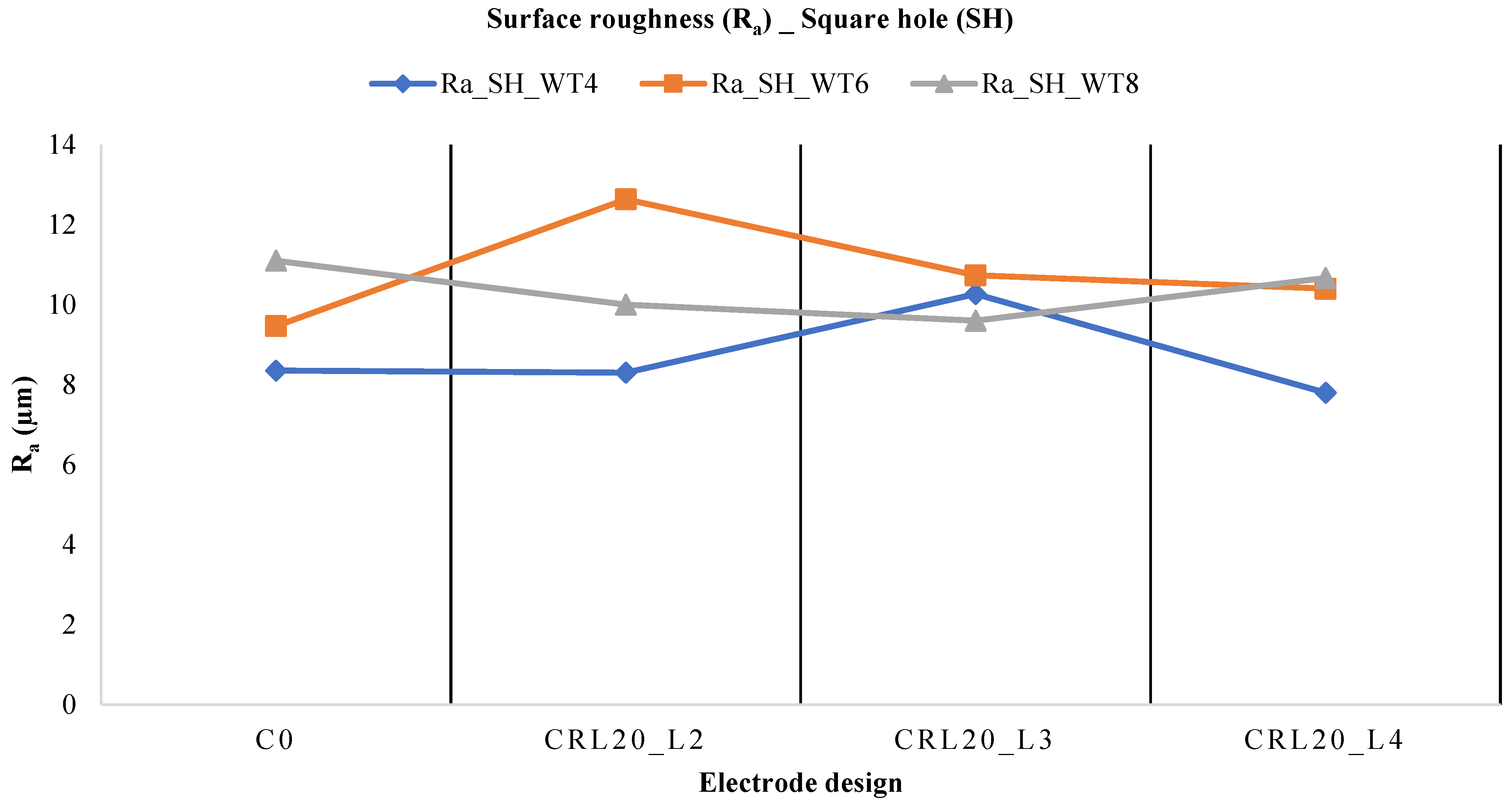
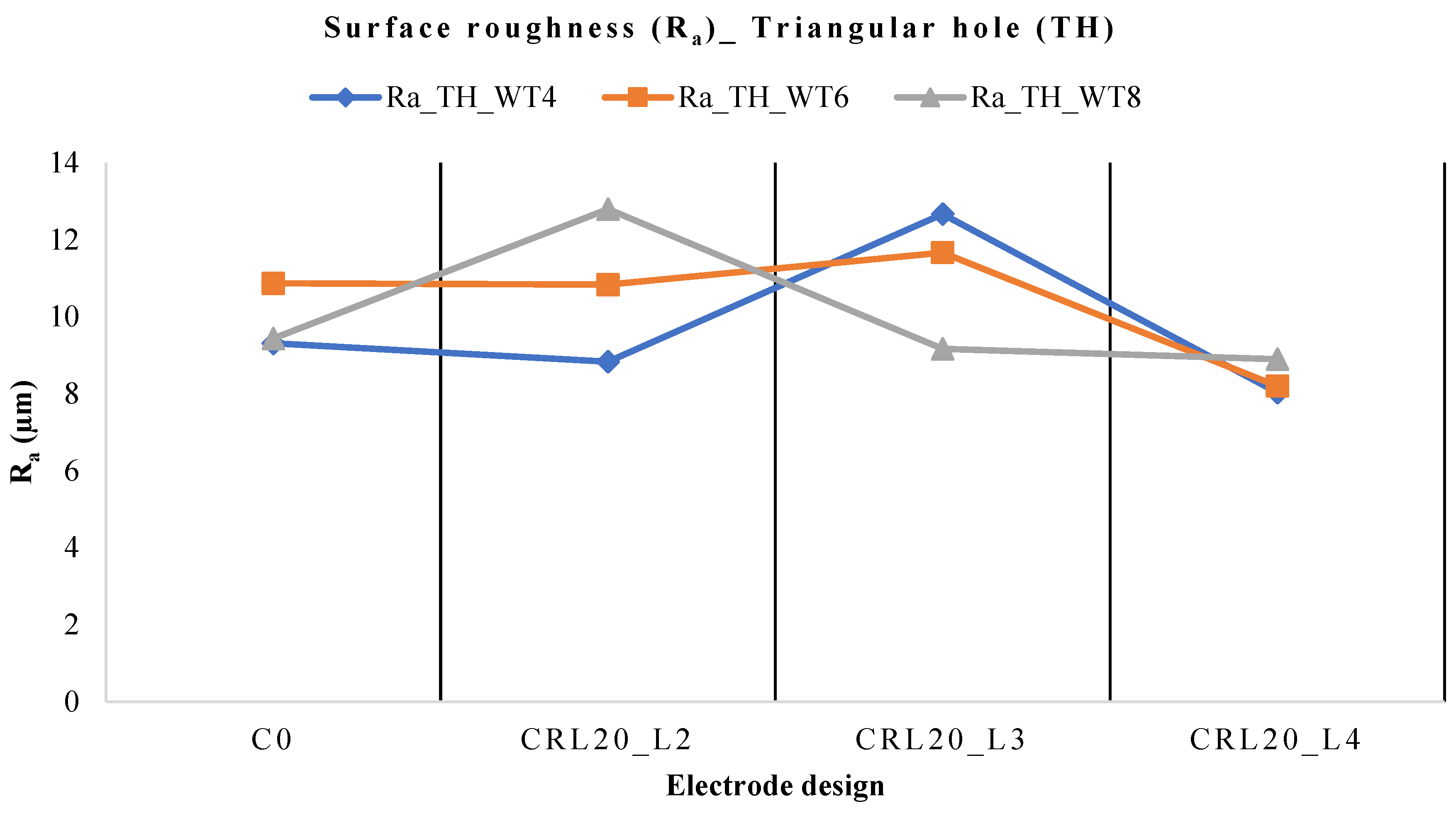
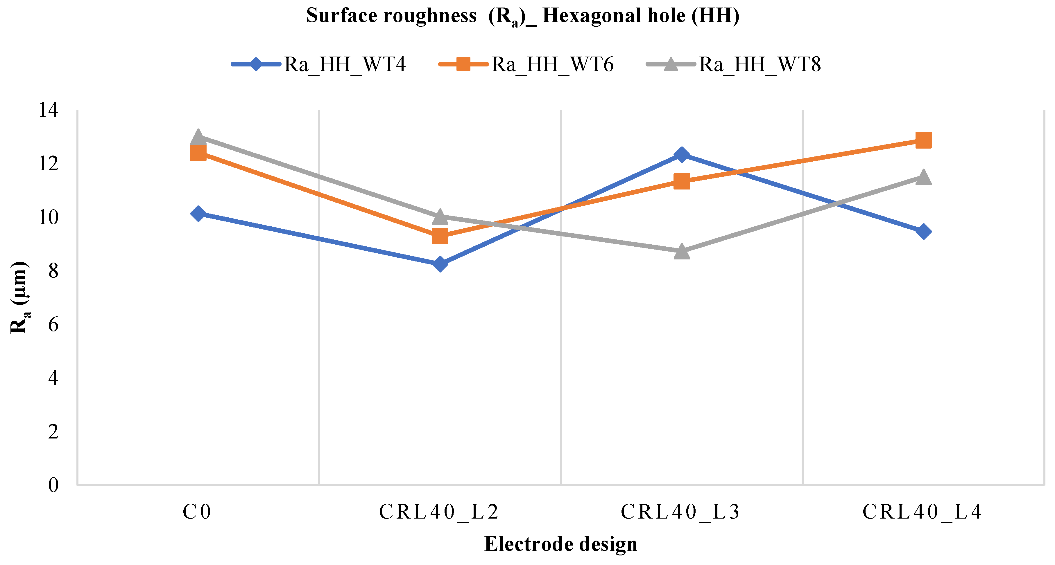
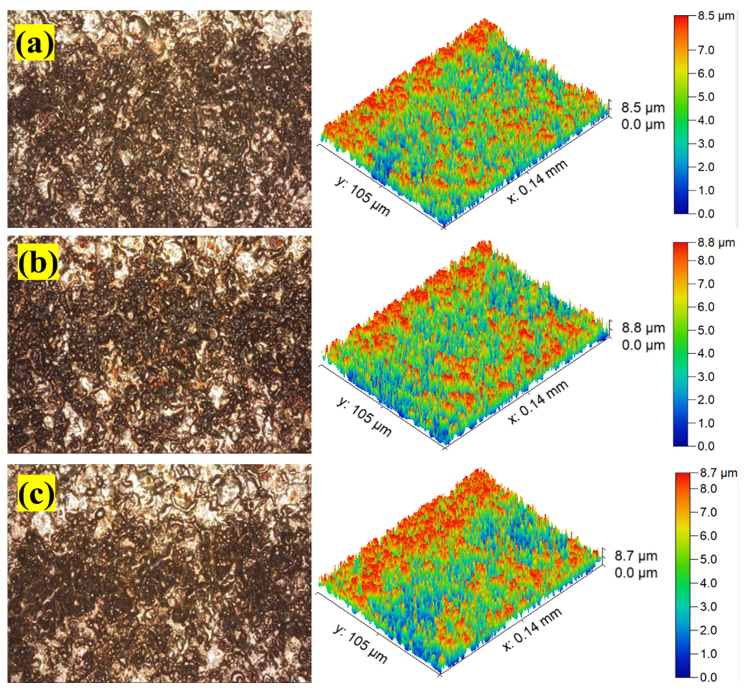
3.3. Parametric Effects on Surface Roughness

The surface roughness (SR) of the machined workpiece has also been evaluated during the EDM of D2 material and has been presented in the form of a line graph as shown in Figure 12. It is clear from Figure 12 that when a conventional square Cu electrode was engaged to machine the D2-grade, then the least workpiece thickness (4 mm) gave the better surface finish compared to the other two workpiece thicknesses. The reason for the high SR is that it is associated with the production of irregular and side sparking which results in the poor surface finish. Figure 3 illustrates that the conventional Cu electrode gave a poor surface finish due to side sparking. The 3D profilometry shown in Figure 13a of a machined specimen illustrates the large, heightened peaks and valleys which are in favor of a poorer surface finish. However, when a land thickness of 2 mm was attached with the Cu electrode then again, the SR obtained was also small as shown in Figure 12, when a 4 mm workpiece thickness is employed. The poor SR in the case of a 6 mm and 8 mm workpiece thickness was due to the high electrical conductivity of a Cu electrode which produced high discharge heat and melts and vaporizes the base material as presented in Figure 13b. Moreover, when the land thickness of 4 mm was utilized against the 8 mm thickness of the workpiece, then least SR was achieved. The reason for the least SR magnitude was due to the improvements made in the electrode (land thickness) and explained in previous sections as reference to Figure 3. The 3D profilometry shown in Figure 13c depicts the better results of SR in terms of short, heightened peaks and valleys.
The SR of machined specimens of a D2 base material has also been investigated by engaging the triangular Cu electrode with distinct designs as shown Figure 14. From Figure 14, the least SR was obtained by the conventional Cu electrode with the 4 mm workpiece thickness. However, the SR gained by the other two workpiece thicknesses was higher than that described above. The microscopic image shown in Figure 15a highlights the short, heightened peaks and valleys on the workpiece surface which are in favor of a greater surface finish. When the land thickness of 2 mm is employed, then a 4 mm workpiece thickness again presents the least SR compared to other combinations. The basic reason for this is associated with the reduction of irregular sparking which happened in a conventional Cu electrode. The 3D surface profilometry shown in Figure 15b illustrates a little higher peaks and valleys compared to the previous case. Moreover, when the land thickness of 4 mm along with a triangular Cu electrode were used against the 8 mm workpiece thickness, then minimum SR was obtained. This least SR was due to the impeding of irregular sparking of the Cu electrode. The surface profilometry depicts the better surface finish as compared to Figure 15c.
The surface roughness (Ra) has also been determined by utilizing the hexagonal electrode against the D2 base material with different types of electrode designs. The graphical presentation of results is shown in Figure 16 whereas the surface profilometry is provided in Figure 17.
The minimum Ra was obtained by employing the conventional Cu electrode with a 4 mm workpiece thickness. The other two combinations of workpiece thickness gave higher SR, which was due to irregular sparking and a high surface area of the hexagonal Cu electrode. The surface profilometry shown in Figure 17a represents the heightened peaks and valleys which is due to irregular sparking. The land thickness of 2 mm with the Cu electrode and 4 mm workpiece thickness results in the smaller Ra compared to the other two combinations of workpiece thickness (6 mm and 8 mm). The reason is associated with the rapid heat transfer generated by the Cu electrode to the workpiece surface and results in the lesser SR. The surface profilometry shown in Figure 17b provides a better understanding of less SR. When the land thickness of 3 mm and 4 mm were used against the workpiece thicknesses (4 mm, 6 mm, and 8 mm) then high SR was obtained as shown in Figure 16. The 3D surface profilometry depicts the poorer surface finish which is due to irregular sparking. If a comparison is developed among the different SRs obtained by square, triangular, and hexagonal Cu electrodes, then a square Cu electrode gave the better surface finish or less SR (7.8 μm) compared to other combinations of land thickness and workpiece thickness. The above magnitude of SR is 62.43%, and 66.66% better than the highest SR magnitude obtained by triangular Cu electrode with land thickness 3 mm, and conventional hexagonal Cu electrode with no land thickness, respectively.

3.4. Composite Desirability Based Multi-Response Optimization

Based on the results and their analysis for each type of non-circular hole, it is clear that determining the most appropriate electrode design for dealing with all three machining reactions (material removal rate, tool wear rate, and surface roughness) is difficult. These are contradictory responses, as a high rate of material removal will result in increased surface roughness of the machined hole and TWR on the electrode. A trade-off among these reactions is required. Therefore, the electrode design resulting in multi-response optimized values of each response has been determined using the composite desirability function approach (CDFA). The composite desirability value runs from 0 to 1, and its number around 0.70–0.80 indicates good desirability [39,40]. In Figure 18, the optimization results are displayed. The optimal values of the three replies and the composite desirability rating are shown in the left-side columns of Figure 18. The level and ideal value of the variables, which in this case are the land thickness and the workpiece thickness, are shown by the top rows in Figure 18. In each of the three examples (square, triangular, and hexagonal holes), the composite desirability has been determined to be close to 0.70. Figure 18a indicates that the land thickness of 2 mm and workpiece thickness of 4 mm are the optimal combination for achieving the lowest surface roughness (9.0467 μm), lowest TWR (14.3625 × 106 μm3/s), and highest MRR (274.1275 × 106 μm3/s) while cutting square cross-sectional holes with a composite desirability of 0.6710. While, in the case of triangular holes EDM machining, the appropriate optimal electrode design parameters are land thickness = 4 mm and workpiece thickness = 8 mm, which results in low surface roughness (8.3925 μm), compromised MRR (189.1425 × 106 μm3/s), and TWR (31.210 × 106 μm3/s) with a composite desirability of 0.7138 as depicted in Figure 18b. In the case of machining hexagonal shaped holes, the optimized values for surface roughness, tool wear rate, and material removal rate are 9.2250 μm, 12.1517 × 106 μm3/s, and 218.5508 × 106 μm3/s, respectively, at the optimal combination of land thickness = 2 mm and workpiece thickness = 8 mm as demonstrated in Figure 18c.
If a comparison is made among the TWR of the current study with the previous published work, then it is found that TWR obtained by the square hole electrode (3.87 × 106 μm3/s) of this study is significantly improved/less than the lowest TWR (13.65 × 106 μm3/s) presented in [41]. The MRR of the current study by using a square hole electrode (307.21 μm3/s is prominently better than the maximum MRR (294.33 μm3/s) as presented in [38].

4. Conclusions

Different non-conventional electrode designs have been used in the electric discharge machining of D2 steel to create square, triangular, and hexagonal holes. Material removal rate (MRR), tool wear rate (TWR), and surface roughness (SR) are used as performance indicators to select the most appropriate electrode design and its associated design parameters, resulting in improved machining performance. To measure the response indicators, different process parameters have been used including two electrode designs—conventional design (C0) and circular relief design (CRL)—three relief angles (0, 20°, and 40°), three-hole shapes (square, triangular, and hexagonal), varying workpiece thicknesses (4, 6, and 8 mm), and land heights (2, 3, and 4 mm). For the comparison purpose, the electrode with the standard electrode design (a uniform cross-section along its whole length) is utilized for each shape. Inferences that can be made based on the experimental data, results, analysis, and discussion include the following:
  • The circular relief angled tool designs (CRL) offer better MRR than the traditional tools for machining or cutting square, triangular, and hexagonal non-circular hole profiles.
  • Among those three non-circular hole profiles (i.e., square, triangular, and hexagonal profiles), the highest MRR (317.24 × 106 μm3/s) is resulted while machining hexagonal holes.
  • While machining hexagonal and triangular holes, more tool erosion occurred compared to machining square holes. In the case of square holes, there is evidence of the lowest TWR of 3.87 × 10⁶ m3/s, which is 62.93% and 122.99% less than the reported TWR rate for the triangular and hexagonal tools, respectively. The lowest surface roughness Ra = 7.8 μm has been obtained when a square Cu electrode is used with a 4 mm land and 4 mm workpiece thickness. The magnitude of surface roughness is 62.43%, and 66.66% better than the obtained surface roughness by a triangular Cu electrode with a land thickness 3 mm, and conventional hexagonal Cu electrode with no land thickness, respectively.
  • Taking into consideration the desired outcomes of achieving a high material removal rate, low tool wear rate, and surface roughness simultaneously, the optimal tool design parameters are determined for three distinct types of non-circular through-holes (specifically square, triangular, and hexagonal) in D2 steel. These parameters have been identified through a comprehensive composite desirability analysis, ensuring an ideal combination of performance factors.
    For the square cross-sectional through-holes, the optimal tool design parameters recommended are: tool design = circular relief angled design (CRL), relief angle = 20 deg, land thickness = 2 mm, and workpiece thickness = 4 mm.
    Similarly, for the triangular through-holes, the most suitable tool design parameters recommended are: tool design = circular relief angled design (CRL), relief angle = 20 deg, land thickness = 4 mm, and workpiece thickness = 8 mm.
    Lastly, for the hexagonal through-holes, the recommended tool design parameters are: tool design = circular relief angled design (CRL), relief angle = 40 deg, land thickness = 2 mm, and workpiece thickness = 8 mm.
These tool design parameters have been determined to optimize the manufacturing process and achieve the desired outcomes of high MRR, low TWR, and low SR for three non-circular through-hole shapes in AISI D2 steel. These insights will empower the manufacturing industry practitioners to fabricate complex shapes with better surface quality (SR), improved productivity (MRR), and cost-effectiveness (TWR). The future research directions include investigations of the effects of researched electrode designs on dimensional accuracies of the machined holes. The authors are already working on this future area of investigation.

Author Contributions

Conceptualization, M.R., N.A.M. and N.A.; data curation, M.R.; formal analysis, N.A.; funding acquisition, A.U.R.; investigation, N.A.M. and M.Q.S.; methodology, N.A. and A.U.R.; project administration, N.A.M.; resources, N.A.M. and M.Q.S.; software, S.Z. and M.A.A.; supervision, N.A.M. and M.Q.S.; validation, M.Q.S.; visualization, M.A.A.; writing—original draft, M.R.; writing—review and editing, A.U.R., S.Z. and M.A.A. All authors have read and agreed to the published version of the manuscript.

Funding

This research was funded by Researchers Supporting Project number (RSPD2023R701), King Saud University, Riyadh, Saudi Arabia.

Data Availability Statement

Not applicable.

Acknowledgments

The authors are thankful to King Saud University for funding this work through Researchers Supporting Project number (RSPD2023R701), King Saud University, Riyadh, Saudi Arabia.

Conflicts of Interest

The authors declare no conflict of interest.

References

  1. Davis, J.R. ASM Specialty Handbook: Tool Materials; ASM International: Almere, The Netherlands, 1995; ISBN 978-0-87170-545-7. [Google Scholar]
  2. Hickey, K. Tooling and Die Wear. Available online: https://ahssinsights.org/forming/tooling/tooling-and-die-wear/ (accessed on 7 August 2023).
  3. Campi, F.; Favi, C.; Mandolini, M.; Germani, M. Using Design Geometrical Features to Develop an Analytical Cost Estimation Method for Axisymmetric Components in Open-Die Forging. Procedia CIRP 2019, 84, 656–661. [Google Scholar] [CrossRef]
  4. Tsai, K.-M.; Wang, P.-J. Semi-Empirical Model of Surface Finish on Electrical Discharge Machining. Int. J. Mach. Tools Manuf. 2001, 41, 1455–1477. [Google Scholar] [CrossRef]
  5. Qudeiri, J.E.A.; Zaiout, A.; Mourad, A.-H.I.; Abidi, M.H.; Elkaseer, A. Principles and Characteristics of Different EDM Processes in Machining Tool and Die Steels. Appl. Sci. 2020, 10, 2082. [Google Scholar] [CrossRef]
  6. Valaki, J.B.; Rathod, P.P. Assessment of Operational Feasibility of Waste Vegetable Oil Based Bio-Dielectric Fluid for Sustainable Electric Discharge Machining (EDM). Int. J. Adv. Manuf. Technol. 2016, 87, 1509–1518. [Google Scholar] [CrossRef]
  7. Bhatia, K.; Singla, A.; Sharma, A.; Sengar, S.S.; Selokar, A. A Review on Different Dielectric Fluids and Machining of Si3N4 and Al2O3 Composites via EDM. In Advances in Industrial and Production Engineering; Shanker, K., Shankar, R., Sindhwani, R., Eds.; Lecture Notes in Mechanical Engineering; Springer: Singapore, 2019; pp. 585–596. ISBN 9789811364112. [Google Scholar]
  8. Wang, C.; Qiang, Z. Comparison of Micro-EDM Characteristics of Inconel 706 between EDM Oil and an Al Powder-Mixed Dielectric. Adv. Mater. Sci. Eng. 2019, 2019, 5625360. [Google Scholar] [CrossRef]
  9. Hourmand, M.; Sarhan, A.A.D.; Farahany, S.; Sayuti, M. Microstructure Characterization and Maximization of the Material Removal Rate in Nano-Powder Mixed EDM of Al-Mg2Si Metal Matrix Composite—ANFIS and RSM Approaches. Int. J. Adv. Manuf. Technol. 2019, 101, 2723–2737. [Google Scholar] [CrossRef]
  10. Batish, A.; Bhattacharya, A.; Kumar, N. Powder Mixed Dielectric: An Approach for Improved Process Performance in EDM. Part. Sci. Technol. 2015, 33, 150–158. [Google Scholar] [CrossRef]
  11. Bahgat, M.M.; Shash, A.Y.; Abd-Rabou, M.; El-Mahallawi, I.S. Influence of Process Parameters in Electrical Discharge Machining on H13 Die Steel. Heliyon 2019, 5, e01813. [Google Scholar] [CrossRef]
  12. Klocke, F.; Schwade, M.; Klink, A.; Veselovac, D. Analysis of Material Removal Rate and Electrode Wear in Sinking EDM Roughing Strategies Using Different Graphite Grades. Procedia CIRP 2013, 6, 163–167. [Google Scholar] [CrossRef]
  13. Younis, M.A.; Abbas, M.S.; Gouda, M.A.; Mahmoud, F.H.; Abd Allah, S.A. Effect of Electrode Material on Electrical Discharge Machining of Tool Steel Surface. Ain Shams Eng. J. 2015, 6, 977–986. [Google Scholar] [CrossRef]
  14. Sahu, J.; Shrivastava, S.; Mohanty, C.; Mishra, S.; Mahanta, T.K. Effect of Polarity on MRR and TWR in Electric Discharge Machining. In Advances in Mechanical Processing and Design; Pant, P., Mishra, S.K., Mishra, P.C., Eds.; Lecture Notes in Mechanical Engineering; Springer: Singapore, 2021; pp. 543–550. ISBN 9789811577789. [Google Scholar]
  15. Kumar, S.; Sharma, V. Current Scenario in Optimization of Machining Parameters While Electric Discharge Machining for Biocompatible Ti-Alloy: A Review. In Advances in Engineering Materials; Sharma, B.P., Rao, G.S., Gupta, S., Gupta, P., Prasad, A., Eds.; Lecture Notes in Mechanical Engineering; Springer: Singapore, 2021; pp. 473–480. ISBN 978-981-336-028-0. [Google Scholar]
  16. Abed, F.N.; Ramesh, V.; Fadhil Jwaid, M.; Agarwal, N.; Koundal, D.; Mohamed Ibrahim, A. Enhancement Modelling Based on Electrical Discharge Machining Successive Discharges. Adv. Mater. Sci. Eng. 2022, 2022, 8017375. [Google Scholar] [CrossRef]
  17. Kitada, R.; Wang, Q.; Tsuetani, S.; Okada, A. Influence of Surface Roughness of Die Sinking EDM on Mold Releasability in Compression Molding of Thermosetting Phenol Resin. Procedia CIRP 2022, 113, 238–243. [Google Scholar] [CrossRef]
  18. Dwaraka, R.; Arunachalam, N. Investigation on Non-Invasive Process Monitoring of Die Sinking EDM Using Acoustic Emission Signals. Procedia Manuf. 2018, 26, 1471–1482. [Google Scholar] [CrossRef]
  19. Sharma, S.; Kumar Vates, U.; Bansal, A. Influence of Die-Sinking EDM Parameters on Machining Characteristics of Alloy 625 and Alloy 718: A Comparative Analysis. Mater. Today Proc. 2022, 50, 2493–2499. [Google Scholar] [CrossRef]
  20. Shyn, C.S.; Rajesh, R.; Dev Anand, M. Modeling and Prediction of Die Sinking EDM Process Parameters for A6061/6%B4C Metal Matrix Composite Material. Mater. Today Proc. 2021, 42, 677–685. [Google Scholar] [CrossRef]
  21. Phang, Y.M.; Asmelash, M.; Hamedon, Z.; Azhari, A. Investigation on Turning Operation Using Die Sinking EDM Process. Mater. Today Proc. 2021, 46, 1569–1573. [Google Scholar] [CrossRef]
  22. Chou, S.-H.; Wang, A.-C. Investigating and Removing the Re-Sticky Debris on Tungsten Carbide in Electrical Discharge Machining. Int. J. Adv. Manuf. Technol. 2014, 71, 1151–1158. [Google Scholar] [CrossRef]
  23. Yadav, V.K.; Kumar, P.; Dvivedi, A. Performance Enhancement of Rotary Tool Near-Dry EDM of HSS by Supplying Oxygen Gas in the Dielectric Medium. Mater. Manuf. Process. 2019, 34, 1832–1846. [Google Scholar] [CrossRef]
  24. Cui, J.; Chu, Z. Composite Motion Design Procedure for Vibration Assisted Small-Hole EDM Using One Voice Coil Motor. Shock Vib. 2016, 2016, 4179296. [Google Scholar] [CrossRef]
  25. Khajuria, A.; Bedi, R.; Singh, B.; Akhtar, M. EDM Machinability and Parametric Optimisation of 2014Al/Al2O3 Composite by RSM. Int. J. Mach. Mach. Mater. 2018, 20, 536–555. [Google Scholar] [CrossRef]
  26. Manikandan, N.; Raju, R.; Palanisamy, D.; Binoj, J.S. Optimisation of Spark Erosion Machining Process Parameters Using Hybrid Grey Relational Analysis and Artificial Neural Network Model. Int. J. Mach. Mach. Mater. 2019, 22, 1–23. [Google Scholar] [CrossRef]
  27. Kumar, P.; Parkash, R. Experimental Investigation and Optimization of EDM Process Parameters for Machining of Aluminum Boron Carbide (Al–B4C) Composite. Mach. Sci. Technol. 2016, 20, 330–348. [Google Scholar] [CrossRef]
  28. Singh, J.; Sharma, R.K. Multi-Objective Optimization of Green Powder-Mixed Electrical Discharge Machining of Tungsten Carbide Alloy. Proc. Inst. Mech. Eng. Part C J. Mech. Eng. Sci. 2018, 232, 2774–2786. [Google Scholar] [CrossRef]
  29. Rajamanickam, S.; Prasanna, J. Multi Objective Optimization during Small Hole Electrical Discharge Machining (EDM) of Ti-6Al-4V Using TOPSIS. Mater. Today Proc. 2019, 18, 3109–3115. [Google Scholar] [CrossRef]
  30. Ahmad Mufti, N.; Rafaqat, M.; Ahmed, N.; Qaiser Saleem, M.; Hussain, A.; Al-Ahamri, A.M. Improving the Performance of EDM through Relief-Angled Tool Designs. Appl. Sci. 2020, 10, 2432. [Google Scholar] [CrossRef]
  31. Stamping Die Material Types And Characteristics_Low-Alloy Tool, High Speed Steel, Base Steel, Traditional Mold Steel, Cr12 and Cr12MoV. Available online: https://metalpartss.com/Stamping_Die_Material_Types_And_Characteristics/ (accessed on 7 August 2023).
  32. Mahajan, R.; Krishna, H.; Singh, A.K.; Ghadai, R.K. A Review on Copper and Its Alloys Used as Electrode in EDM. IOP Conf. Ser. Mater. Sci. Eng. 2018, 377, 012183. [Google Scholar] [CrossRef]
  33. Sharma, A.; Kumar Sinha, A. Rotary Electric Discharge Machining of AISI D2 Tool Steel: Present and Future Scope. Mater. Today Proc. 2018, 5, 18562–18567. [Google Scholar] [CrossRef]
  34. Patel, N.J. Review on Effects of Electrode in Electrical Discharge Machining Process. Int. J. Res. Rev. 2021, 8, 91. [Google Scholar] [CrossRef]
  35. Guu, Y.H. AFM Surface Imaging of AISI D2 Tool Steel Machined by the EDM Process. Appl. Surf. Sci. 2005, 242, 245–250. [Google Scholar] [CrossRef]
  36. Tool Steels, 5th Edition—George Adam Roberts, Richard Kennedy, G. Krauss—Google Books. Available online: https://books.google.com.pk/books?id=ScphevR_eP8C&printsec=copyright&redir_esc=y#v=onepage&q&f=false (accessed on 3 February 2020).
  37. D2 Tool Steel—High-Carbon, High-Chromium, Cold-Work Steel (UNS T30402). Available online: https://www.azom.com/article.aspx?ArticleID=6214 (accessed on 27 January 2020).
  38. Rafaqat, M.; Mufti, N.A.; Saleem, M.Q.; Ahmed, N.; Rehman, A.U.; Ali, M.A. Machining of Triangular Holes in D2 Steel by the Use of Non-Conventional Electrodes in Die-Sinking Electric Discharge Machining. Materials 2023, 16, 3865. [Google Scholar] [CrossRef]
  39. Yarar, E.; Karabay, S. Investigation of the Effects of Ultrasonic Assisted Drilling on Tool Wear and Optimization of Drilling Parameters. CIRP J. Manuf. Sci. Technol. 2020, 31, 265–280. [Google Scholar] [CrossRef]
  40. Yarar, E.; Koç, F.G.; Angigün, F.; Demirci, Ş.; Makas, T. Multi-Response Optimization and Machinability Research of Forging and Heat Treatment Parameters in Piston Production. Multiscale Multidiscip. Model. Exp. Des. 2023, 6, 305–317. [Google Scholar] [CrossRef]
  41. Rafaqat, M.; Mufti, N.A.; Saleem, M.Q.; Ahmed, N.; Hussain, A. Electric Discharge Machining of Non-Circular through-Holes: Material Removal and Tool Wear Analysis. J. Braz. Soc. Mech. Sci. Eng. 2023, 45, 135. [Google Scholar] [CrossRef]
Figure 1. Experimental graphical flow illustrations; (a,b) non-conventional electrode designs, (c) various workpiece thickness schematic, (d) machined workpiece after EDM, (e) weight balancer for MRR, (f) weight balancer for TWR, and (g) surface roughness meter.
Processes 11 02661 g001
Figure 2. MRR against land thickness (L2, L3, and L4) and workpiece thickness (WT4, WT6, and WT8) using square electrode designs.
Processes 11 02661 g002
Figure 3. Schematic illustration of sparking phenomena and machined holes with different conventional C0 and non-conventional CRL EDM electrode designs at various land thickness; (a) conventional electrode (C0) with no land, (b) circular relief angled electrode (CRL) with land thickness of 2 mm and (c) circular relief angled electrode (CRL) with land thickness of 4 mm.
Processes 11 02661 g003
Figure 4. MRR against land thickness (L2, L3, and L4) and workpiece thickness (WT4, WT6, and WT8) using triangular electrode designs.
Processes 11 02661 g004
Figure 5. MRR against land thickness (L2, L3, and L4) and workpiece thickness (WT4, WT6, and WT8) using hexagonal electrode designs.
Processes 11 02661 g005
Figure 6. TWR against land thickness (L2, L3, and L4) and workpiece thickness (WT4, WT6, and WT8) using square electrode designs.
Processes 11 02661 g006
Figure 7. TWR using (a) square C0_WT4 (TWR = 26.10 × 106 μm3/s); (b) square CRL20_L3_WT6 (TWR = 16.55 × 106 μm3/s); (c) square CRL20_L4_WT8 (TWR = 12.72 × 106 μm3/s).
Processes 11 02661 g007
Figure 8. TWR land thickness (L2, L3, and L4) and workpiece thickness (WT4, WT6, and WT8) using triangular electrode designs.
Processes 11 02661 g008
Figure 9. TWR using (a) triangular C0_WT4 (TWR = 48.77 × 106 μm3/s); (b) triangular CRL20_L2_WT4 (TWR = 48.82 × 106 μm3/s); (c) triangular CRL20_L4_WT8 (TWR = 33.60 × 106 μm3/s).
Processes 11 02661 g009
Figure 10. TWR against land thickness (L2, L3, and L4) and workpiece thickness (WT4, WT6, and WT8) using hexagonal electrode designs.
Processes 11 02661 g010
Figure 11. TWR using (a) hexagonal C0_WT4 (TWR = 17.07 × 106 μm3/s); (b) hexagonal CRL40_L2_WT4 (TWR = 18.02 × 106 μm3/s); (c) hexagonal CRL40_L2_WT8 (TWR = 9.14 × 106 μm3/s).
Processes 11 02661 g011
Figure 12. Surface roughness (Ra) against land thickness (L2, L3, and L4) and workpiece thickness (WT4, WT6, and WT8) using square electrode designs.
Processes 11 02661 g012
Figure 13. Surface roughness using different electrode design parameters on different workpiece thicknesses: (a) Conventional design employed on 4 mm work thickness; C0_WT4 (Ra = 8.35 μm); (b) circular relief design with 20 degree relief and 2 mm land thickness employed on 6 mm workpiece thickness; CRL20_L2_WT6 (Ra = 8.30 μm); (c) circular relief design with 20 degree relief and 4 mm land thickness employed on 8 mm workpiece thickness; CRL20_L4_WT8 (Ra = 7.8 μm).
Processes 11 02661 g013
Figure 14. Surface roughness (Ra) against land thickness (L2, L3, and L4) and workpiece thickness (WT4, WT6, and WT8) using triangular electrode designs.
Processes 11 02661 g014
Figure 15. Surface roughness using different electrode design parameters on different workpiece thicknesses: (a) conventional design employed on 4 mm workpiece thickness; C0_WT4 (Ra = 7.43 μm); (b) circular relief design with 20 degree relief and 2 mm land thickness employed on 4 mm workpiece thickness; CRL20_L2_WT4 (Ra = 8.83 μm); (c) circular relief design with 20 degree relief and 4 mm land thickness employed on 8 mm workpiece thickness; CRL20_L4_WT8 (Ra = 8.03 μm).
Processes 11 02661 g015
Figure 16. Surface roughness (Ra) against land thickness (L2, L3, and L4) and workpiece thickness (WT4, WT6, and WT8) using hexagonal electrode designs.
Processes 11 02661 g016
Figure 17. Surface roughness using different electrode design parameters on different workpiece thicknesses: (a) conventional design employed on 4 mm workpiece thickness; C0_WT4 (Ra = 10.13 μm); (b) circular relief design with 40 degree relief and 2 mm land thickness employed on 4 mm workpiece thickness; CRL40_L2_WT4 (Ra = 8.25 μm); (c) circular relief design with 40 degree relief and 2 mm land thickness employed on 8 mm workpiece thickness CRL40_L2_WT8 (Ra = 13.00 μm).
Processes 11 02661 g017
Figure 18. Multi-response optimization results corresponding to: (a) square holes, (b) triangular holes, and (c) hexagonal holes.
Processes 11 02661 g018
Table 1. Elemental composition, physical, and mechanical properties of D2 steel [35,36,37].
Elemental Composition (Content %)Physical PropertiesMechanical Properties
C1.5PropertiesValue (Units)PropertiesValue (Units)
Si0.3Density7.7 × 1000 kg/m3Hardness55–62 HRC
Mo1Melting point1421 °CHardness748 HV
Cr12 Poisson’s ratio0.27–0.30
Ni0.3 Elastic modulus210 GPa
V0.8
Co1
FeBalance
Table 2. Design parameters for EDM of D2 steel.
Design ParametersLevels
123
Electrode designConventional (C0)Circular relief (CRL) -
Relief angle (deg)02040
Hole shapeSquare TriangularHexagonal
Land height (mm)234
Work thickness (mm)468
Table 3. Tool’s physical characteristics, and EDM’s parameters.
Tool ParametersEDM Parameters
Tool materialCopperDischarge current20 A
Tool height 50 mmSpark voltage5 V
Shank cross-sectionCircularPulse on-time100 μs
Shank diameter6 mmPulse off-time50 μs
Face length 12 mmSpark time5 s
Face cross-sectionSquareFlush time5 s
Triangular
Hexagonal
Table 4. Experimental design matrix with response measures for various hole shapes; square, triangular, and hexagonal.
ParametersResponse Measures
Square HolesTriangular HolesHexagonal Holes
Tool designLand thickness;
LT (mm)
Workpiece thickness;
WT (mm)
MRR_SH
(×106 μm3/s)
TWR_SH
(×106 μm3/s)
Ra_SH
(μm)
MRR_TH
(×106 μm3/s)
TWR_TH
(×106 μm3/s)
Ra_TH
(μm)
MRR_HH
(×106 μm3/s)
TWR_HH
(×106 μm3/s)
Ra_HH
(μm)
C004288.3826.108.35221.7048.779.31286.2417.0710.13
06265.6221.999.47134.3031.6210.87248.768.9012.40
08162.5110.8411.10140.5727.909.43223.998.6313.00
CRLL224247.5315.638.30251.6148.828.83317.2418.028.25
26242.693.8712.63207.4840.2110.83223.5215.739.30
28307.2115.7610.00212.3638.3612.80192.459.1410.02
CRLL334262.6213.9610.27164.1338.6212.67260.2910.3312.33
36236.4916.5510.73177.2435.5911.67137.0610.9811.33
38244.6613.649.60185.2234.309.17188.8910.258.73
CRLL444207.3614.277.80192.8136.228.03274.0011.909.47
46238.0213.2410.40184.7235.598.20261.5010.9712.87
48214.7712.7210.67202.8833.608.90243.8611.0611.50
Disclaimer/Publisher’s Note: The statements, opinions and data contained in all publications are solely those of the individual author(s) and contributor(s) and not of MDPI and/or the editor(s). MDPI and/or the editor(s) disclaim responsibility for any injury to people or property resulting from any ideas, methods, instructions or products referred to in the content.

