1. Introduction
China has abundant shale gas resources, accounting for approximately 20% of the global reserves. However, the low porosity and permeability characteristics of shale formations often require the use of hydraulic fracturing techniques for their development. Hydraulic fracturing has been widely used in the oil extraction industry, with hundreds of fracturing operations performed every year under different geological conditions, and is known as a very routine measure to increase production. By creating a network of hydraulic fractures through horizontal well hydraulic fracturing, the fractures and pores within the shale gas reservoir are effectively connected, ultimately enhancing gas production rates. Due to the complex underground conditions and varying mechanisms of natural fractures and hydraulic fractures in different shale formations, further research is needed to understand the impact mechanisms of natural fractures and hydraulic fractures [
1]. Clarifying the fracture expansion mechanism of hydraulic fracturing under different circumstances can guide the fracturing construction operation of horizontal wells and better control the formation state of a fracture network, thus improving the fracturing effect.
Shale reservoirs are characterized by complex natural fracture structures, which have a significant impact on hydraulic fractures and have attracted the attention of scholars both domestically and internationally. Warpinski [
2,
3] proposed that under the influence of natural fractures, hydraulic fractures tend to propagate along the direction of natural fractures, resulting in the formation of multiple fractures. Additionally, the opening of micro-fractures can cause fluid losses to exceed the rate of fracture development. Jin Yan [
4] presented three initiation modes of hydraulic fractures under the influence of natural fractures and established corresponding models for calculating initiation pressures. Zeng Qingdong et al. [
5] analyzed the effects of elastic modulus, Poisson’s ratio, and hydraulic fracture angle on fracture propagation. Arash [
6] conducted a systematic study on the impact of natural fracture shapes on hydraulic fractures, analyzing the deformation patterns of natural fractures in three stages: pre-crossing, crossing, and post-crossing. Fu et al. [
7] investigated the stress interference between natural fractures and hydraulic fractures, validated the expansion of individual hydraulic fractures, and conducted laboratory simulations using a natural fracture network to simulate hydraulic fracture propagation. Hou Bing et al. [
8] analyzed the effects of the angle between natural fractures and hydraulic fractures, as well as the differential horizontal stress, on fracture propagation. Guan Bing [
9] examined the influence of perturbations in random natural fractures on hydraulic fractures. Liu Jing [
10] analyzed the effects of fracture spacing, differential horizontal stress, and fracture length on the morphology of fractures during simultaneous multi-cluster expansion.
This article establishes a finite element model of multi-fracture propagation in horizontal wells in shale reservoirs under the disturbance of natural fractures, based on the finite element method. It investigates the effects of differential stress, elastic modulus, natural fracture angle, and the number of natural fracture groups on fracture development. Through quantitative analysis of the degree of hydraulic fracture development, natural fracture development, fracture propagation morphology, and stress field distribution, the model reveals the interaction mechanisms between natural fractures and hydraulic fractures, as well as the different mechanisms of natural fractures in the formation of fracture networks.
By quantitatively analyzing the degree of hydraulic fracture development, natural fracture development, fracture propagation morphology, and stress distribution, the model aims to reveal the mechanisms underlying the interaction between natural fractures and hydraulic fractures. Additionally, the model provides insights into the different mechanisms involved in the formation of fracture networks in the presence of natural fractures.
2. Analysis and Calculation Model for Multi-Fracture Propagation in Horizontal Wells
When conducting fracturing operations in reservoirs with natural fractures, hydraulic fractures intersect with natural fractures, resulting in the formation of complex fracture networks. After intersecting with natural fractures, several scenarios may occur: Hydraulic fractures directly penetrate through natural fractures and continue to propagate in the original direction; Hydraulic fractures propagate along natural fractures and continue to expand along the ends of the natural fractures; Hydraulic fractures intersect with natural fractures and initially propagate along the direction of the natural fractures, then extend from a weak plane within the natural fractures; Shear sliding occurs after the intersection of natural fractures, and hydraulic fractures propagate from the fracture plane [
11].
2.1. Mechanism of Multi-Fracture Disturbance
When multiple fractures exist in a fracture network, the disturbance stress field in the formation is formed by the superposition of the individual disturbance stresses caused by each fracture. The disturbance stress caused by the nth fracture is specified in the footnote [
12].
In the equation, , , represent the disturbance normal stresses generated by the nth hydraulic fracture, MPa; represents the shear stress generated by the nth hydraulic fracture, MPa; represents the distance to the nth fracture, in meters; represents the net pressure within the nth fracture, MPa; represents the half-height of the nth fracture, in meters.
2.2. Finite Element Fracture Propagation Mechanism
In the study of hydraulic fracturing processes, the fracture initiation and propagation are simulated using cohesive elastic-plastic elements based on the principles of fracture mechanics.
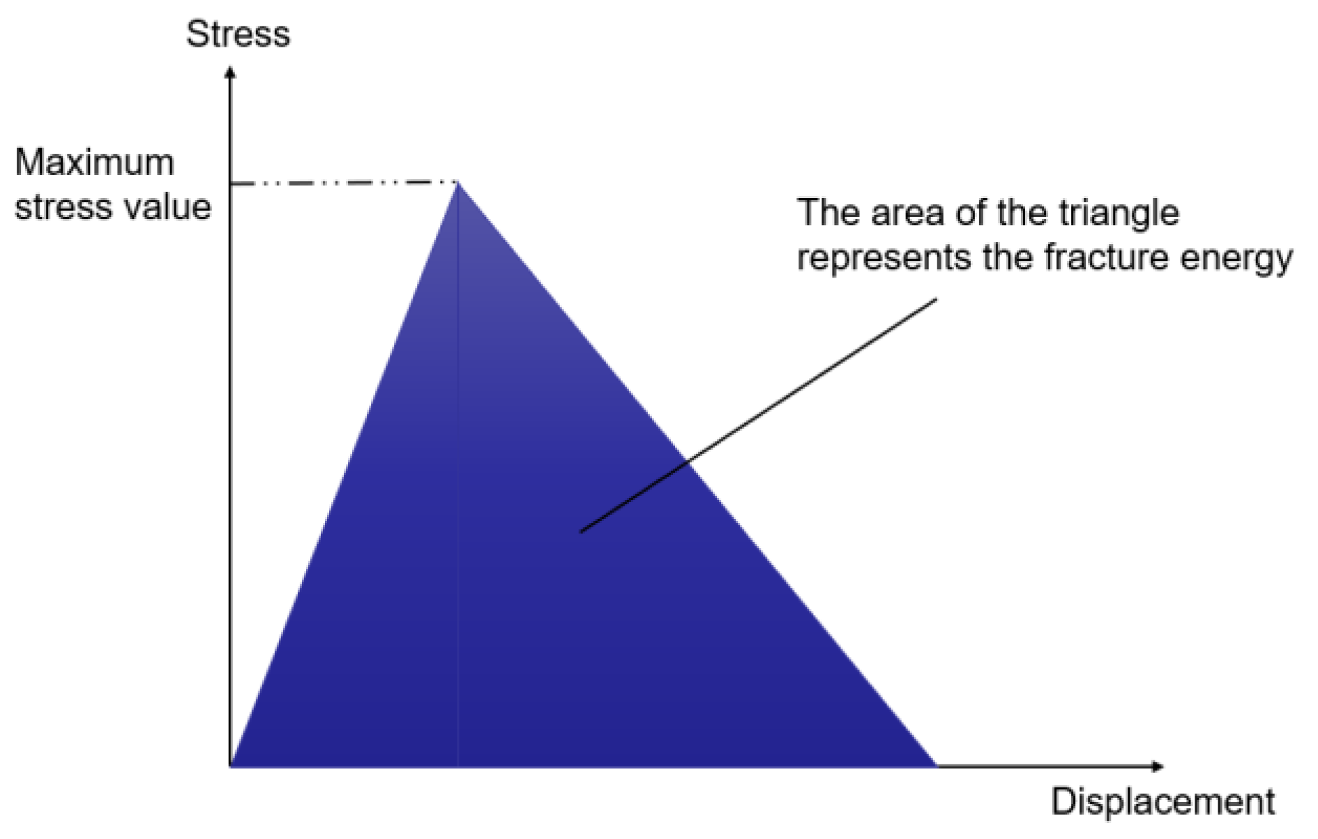
Figure 1 shows the criteria for damage assessment in cohesive elastic-plastic elements [
13].
Criterion for cohesive element fracture initiation:
In the equation, , , and correspond to the stresses along three loading directions ( represents normal stress, while and represent the first and second shear stresses), measured in MPa; , , and are the tensile, first shear, and second shear strengths of intact cohesive elements, respectively, measured in MPa; <> denotes the Macaulay brackets, which indicate that pure compression deformation or stress conditions do not result in damage to the cohesive element.
Evolution of damage in cohesive elements:
In the equation, , , and represent the stresses in three loading directions when assuming that the model undergoes no evolution and remains in a linear elastic deformation process, MPa; , , and represent the actual stresses in three loading directions, MPa; D represents the dimensionless damage coefficient (D = 0 indicates no damage in the material; D = 1 indicates complete material failure).
Considering the composite fracture behavior, the Benzeggagh–Kenane fracture criterion is chosen. When the critical energy for deformation along the first and second shear directions of the cohesive element is equal, the Benzeggagh–Kenane fracture criterion can accurately describe the evolution of damage during fracture propagation.
In the equation,
represents the total critical energy release rate of the cohesive element under mixed mode, Pa·m;
represents the critical energy release rate in the normal direction of the cohesive element, Pa·m;
represents the critical energy release rate in the tangential direction of the cohesive element, Pa·m;
,
, and
represent the energy release rates in the normal, first tangential, and second tangential directions of the cohesive element, respectively, Pa·m;
η is a constant related to the material itself, typically taken as 2.284 [
13].
In addition, the actual total energy release rate, = + + . When =, fracture propagation occurs.
3. Model Establishment
X oilfield adopts the horizontal multi-stage hydraulic fracturing for exploitation and implements multi-cluster fracturing in horizontal wells. During the fracturing operation, it is observed that the fracture propagation is influenced by both natural fractures and multiple induced fractures. Based on the actual geological and construction parameters of the well, a numerical calculation model for the hydraulic fracturing of two clusters is established. Shown in the
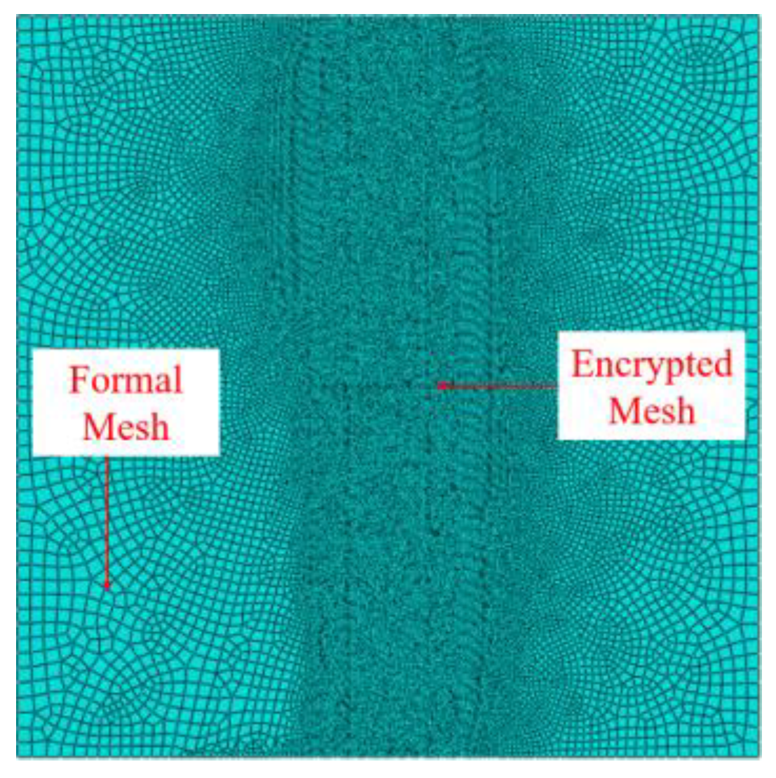
Figure 2, the spacing between the fractures is 5 m. The solid portion is discretized using porous fluid (CPE4P) elements, while the fractures are modeled using cohesive elements with consideration of filtration (COH2D4P). The region of the pre-existing hydraulic fractures is locally refined. A 2D artificial fracture propagation model is constructed within a 60 m × 60 m rectangular area, using mesh commands embedded with global zero-thickness cohesive permeable elements, shown in the
Figure 3. Additional permeable nodes are added to form a discrete body grid model. The initial damage stress values and shear strength elements of the natural fractures are appropriately modified to introduce diversity. The hydraulic fractures are set to be 1 m in length, and the resulting vertical fractures are assumed to be ideal symmetric wing fractures. Some parameters of the model are shown in
Table 1.
The hydraulic fracture radius is relatively small compared to the overall size of the model, so it is possible to simplify the hydraulic fracture accordingly. Different boundary conditions and initial conditions can be applied to the finite element model for the flow field and deformation field. The pictures are from parts of the model that are not affected by the boundary conditions, so the effect of the boundary conditions on this experiment can be disregarded.
In order to study the variability of fracturing patterns between the homogeneous model and the model with the presence of natural fractures, the natural fractures were set as the independent variable with the same other values, and the differences in the fracture extension patterns were observed. The process of fracture propagation in both the mean model and the model with natural fractures is shown in the following figure:
As can be seen in
Figure 4. The hydraulic fracturing of the homogeneous model exhibits bidirectional symmetric expansion, and the morphology of the hydraulic fractures remains relatively consistent. The fractures generally have a shape with wide middle and narrower ends, with the lateral propagation of the fractures occurring mainly towards the outer sides of the fractures. There is almost no displacement in the inter-fracture region. The injection pressure and fracture width of the hydraulic fractures exhibit symmetric consistency.
As can be seen in
Figure 5. In the presence of natural fractures, hydraulic fractures induced by two injection points initially expand symmetrically toward both sides. Once the left hydraulic fracture connects with a natural fracture, it starts propagating along the direction of the natural fracture, and the vertical fractures gradually close. The right hydraulic fracture mainly expands in the opposite direction, exhibiting a shape with wider middle and narrower ends. The lateral propagation of the fractures occurs primarily towards the outer layers of the fractures, with some areas in the inter-fracture region displaying no displacement [
14]. Compared with the homogeneous model, the hydraulic fractures of the mean value model will expand in the direction of the maximum stress, but the model with the presence of natural fractures will have some steering effects due to the presence of natural fractures. The hydraulic fracture that intersects the natural fracture will expand upward along the natural fracture, and the other hydraulic fracture that does not touch the natural crack will expand mainly downward, while the two hydraulic fractures of the homogeneous model expand symmetrically. Hydraulic fracture extension in the presence of natural fractures is more likely to form a fracture network and increase the connection between fractures, and the fracturing effect will be better. The model containing natural fractures is therefore used to study the effect on multi-fracture extension in horizontal wells.
4. Analysis of Results
When conducting hydraulic fracturing operations in horizontal wells, reservoir parameters are uncontrollable. Therefore, when studying hydraulic fracturing in horizontal wells, it is necessary to consider the influence of reservoir parameters on local stresses during the fracturing process. Factors such as stress difference, elastic modulus, fracture angle, and number of fractures all have significant impacts on the local stress field. Analyzing the disturbance patterns of these factors on the local stress field is of the utmost importance [
15].
4.1. Impact of Stress Difference
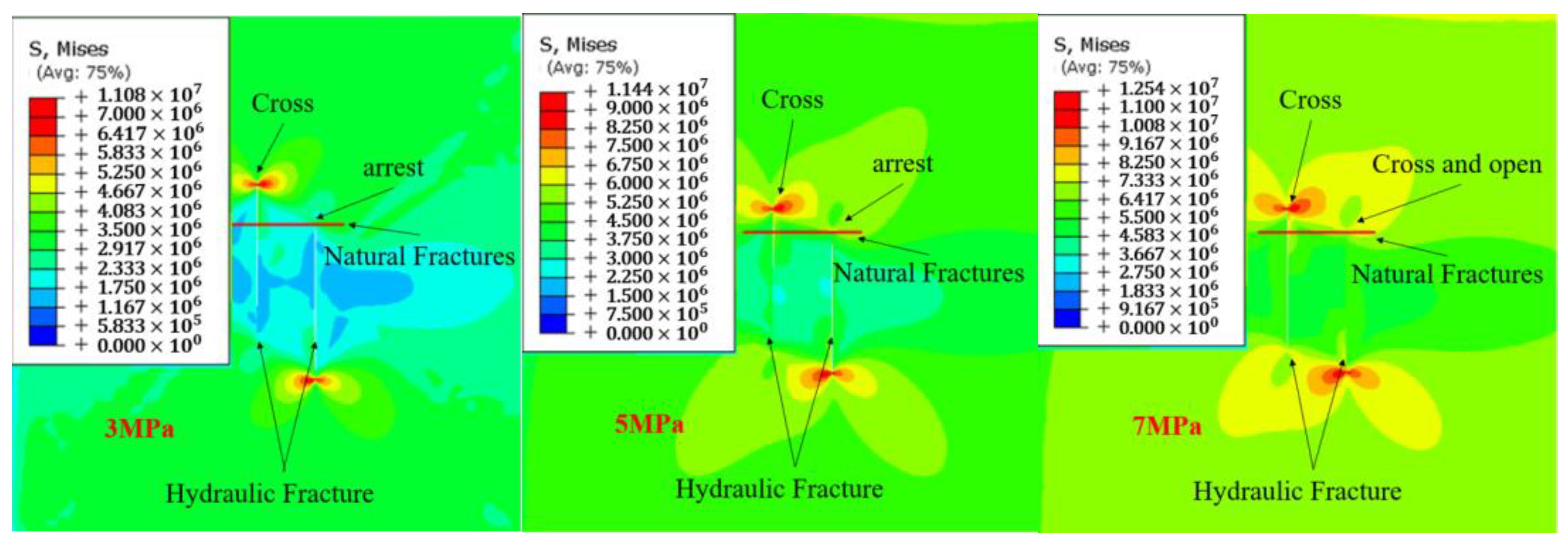
The stress difference has a significant impact on fracture propagation. To investigate the influence of stress difference on fracture propagation, numerical simulations of hydraulic fracturing were conducted with a natural fracture angle of 90° and stress differences of 3 MPa, 5 MPa, and 7 MPa. The stress field distributions for different stress differences were plotted. As shown in
Figure 6.
When the natural fractures are parallel to the maximum horizontal principal stress, the natural fractures have a weaker control over hydraulic fracture propagation. Under a stress difference of 3 MPa, the left hydraulic fracture extends upward through the natural fractures, while the right hydraulic fracture extends downward. The top of the right hydraulic fracture extends to the natural fracture and begins to extend in the direction of the natural fracture. The natural fracture tends to open and divert fracturing fluid.
Under a stress difference of 5 MPa, the left hydraulic fracture directly intersects the natural fractures, while the right hydraulic fracture extends to the location of the natural fractures and then propagates along the direction of the natural fractures. The lateral unfolding of the fractures mainly proceeds to the strata outside the fractures, and the displacement of the strata in the area connected to the tips of the two fractures in the non-primary expansion direction is small.
Under a stress difference of 7 MPa, the hydraulic fractures induced by two injection points exhibit a similar expansion morphology, but in opposite directions. Both hydraulic fractures penetrate the natural fractures. The fractures are all wide in the center and narrow at the ends. The right hydraulic fracture crosses and opens the natural fracture, extends in the direction of the natural fracture and transfers the fracturing fluid, increasing the correlation and complexity between the fractures.
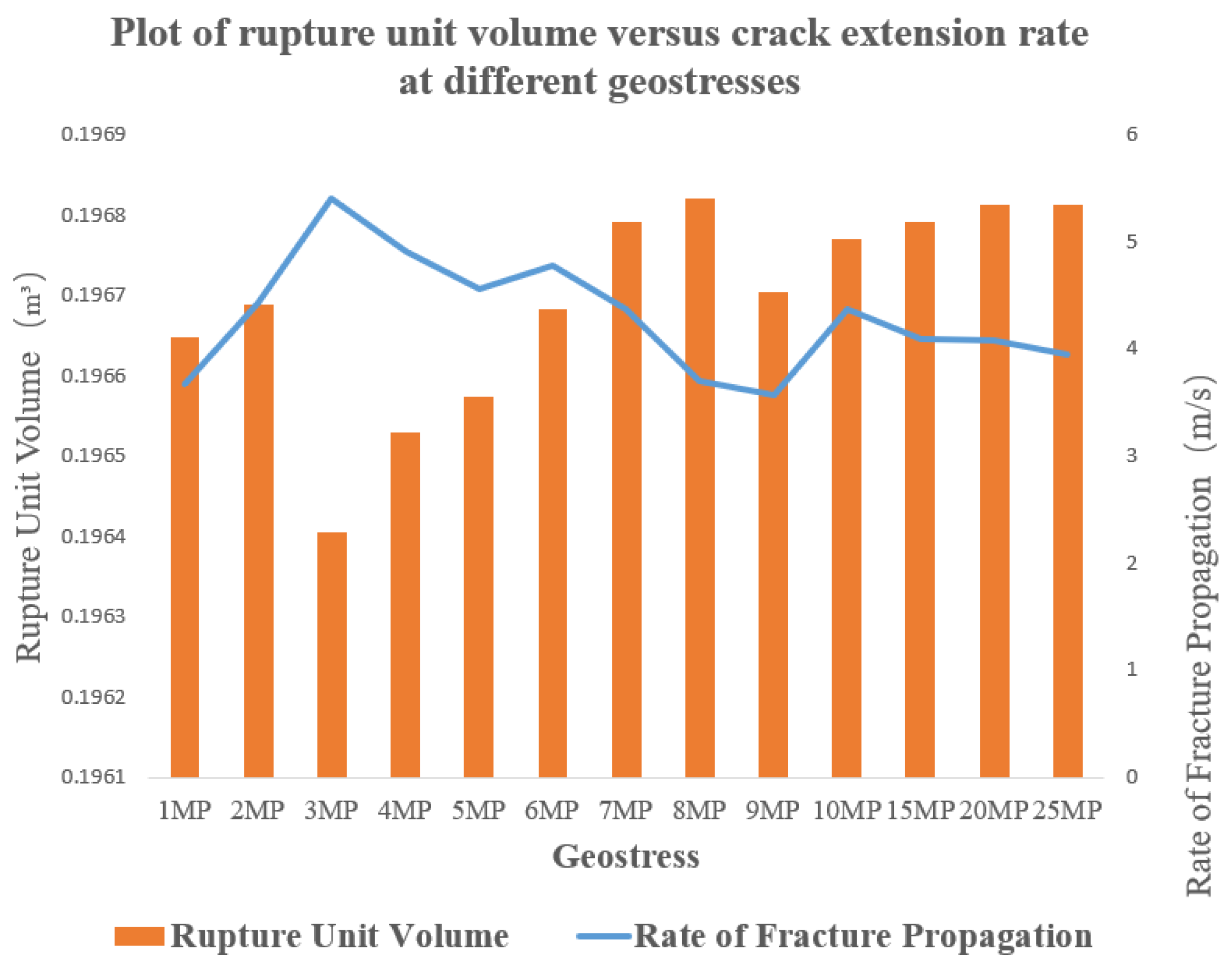
As shown in
Figure 7, with an increase in stress difference, the volume of fractured elements increases, while the fracture propagation rate decreases linearly [
16]. The increase in geostress difference from 1 MPa to 2 MPa increases the volume of rupture unit and the fracture extension rate, which indicates that the geostress difference can promote the tangential and normal flow of fluids within a certain range, which in turn promotes the extension of the fracture tip as well as the two sides of the fracture [
17]. However, when 2 MPa increases to 3 MPa, the fracture expansion rate increases, but the volume of fracture unit decreases sharply, and the fracture channel, which plays the role of inflow, turns into the pore channel, which plays the role of seepage [
18]. With the stress difference from 5 MPa to 10 MPa, then to 15 MPa, 20 MPa, and 25 MPa, the fracture extension rate is decreasing, but the rupture unit volume is increasing, and the rupture unit volume growth rate is decreasing.
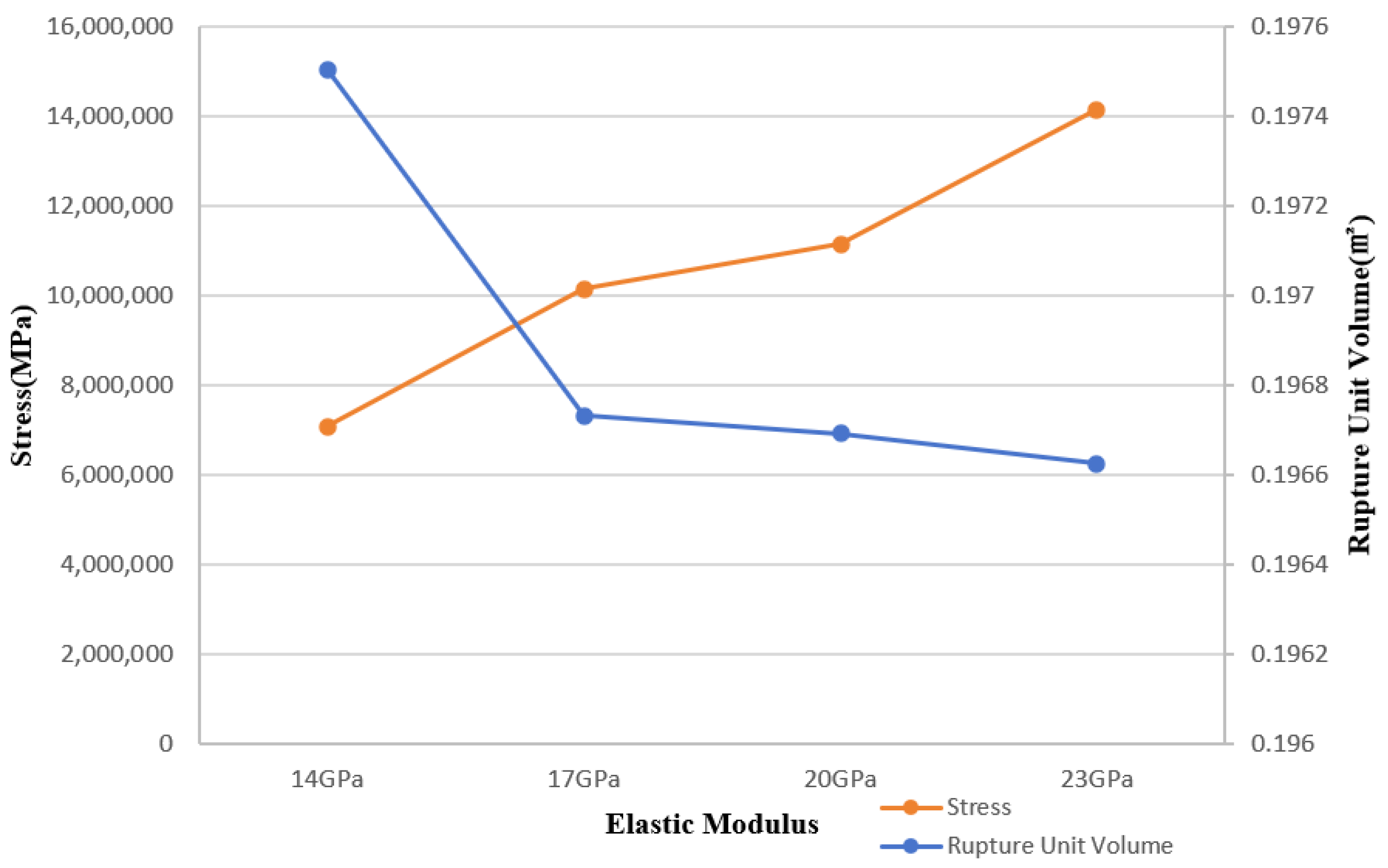
4.2. Effect of Elastic Modulus
By using the same hydraulic fracturing modeling approach, with the exception of changing the elastic modulus, the other parameters remain constant. The changes in fracture propagation are observed and analyzed by measuring elastic moduli of 14 GPa, 17 GPa, 20 GPa, and 23 GPa. The factors influencing fracture propagation under different elastic moduli are calculated and analyzed. As shown in
Figure 8.
When the elastic modulus is 14 GPa, the two hydraulic fractures propagate in opposite directions. The left hydraulic fracture extends to the natural fracture without being influenced by it, while it extends upward through the natural fractures. But the right fracture starts to propagate along the direction of the natural fracture after reaching it [
19].
When the elastic modulus is 17 GPa, the two hydraulic fractures propagate in opposite directions; both penetrate the natural fracture but do not extend in the direction of natural fracture. The fractures are wide in the middle and narrow at both ends; the lateral expansion of the fractures is mainly carried out to the stratum outside the fractures, and the displacement of the stratum in the area connected to the tips of the two fractures in the non-primary expansion direction is small [
20].
When the elastic modulus is 20 GPa, the two hydraulic fractures propagate in opposite directions. The left fracture has some portions that propagate along the direction of the natural fracture when crossing the area of the natural fracture, while the right fracture primarily propagates along the direction of the natural fracture upon reaching it [
21].
From the above
Figure 9, it can be observed that with an increase in elastic modulus, the planar extension pattern of the fracture as well as the pressure has a significant effect. There is a consequent increase in fracture stress, but a consequent decrease in rupture unit volume, and it can be seen in the above figure that there is an inverse relationship between fracture stress and rupture unit volume. As can be seen in
Figure 10, the total length of fractures produced by hydraulic fracture extension increases as the modulus of elasticity increases, and the greater the modulus of elasticity, the shorter the time required to produce the maximum total length of fractures. Additionally, an increase in elastic modulus leads to a reduction in the concentration of pore pressure in the area, resulting in a gradual decrease in the width of the fracture during propagation. Therefore, reservoirs with higher elastic moduli tend to form long and narrow fractures [
22,
23,
24].
4.3. Effect of Fracture Angle
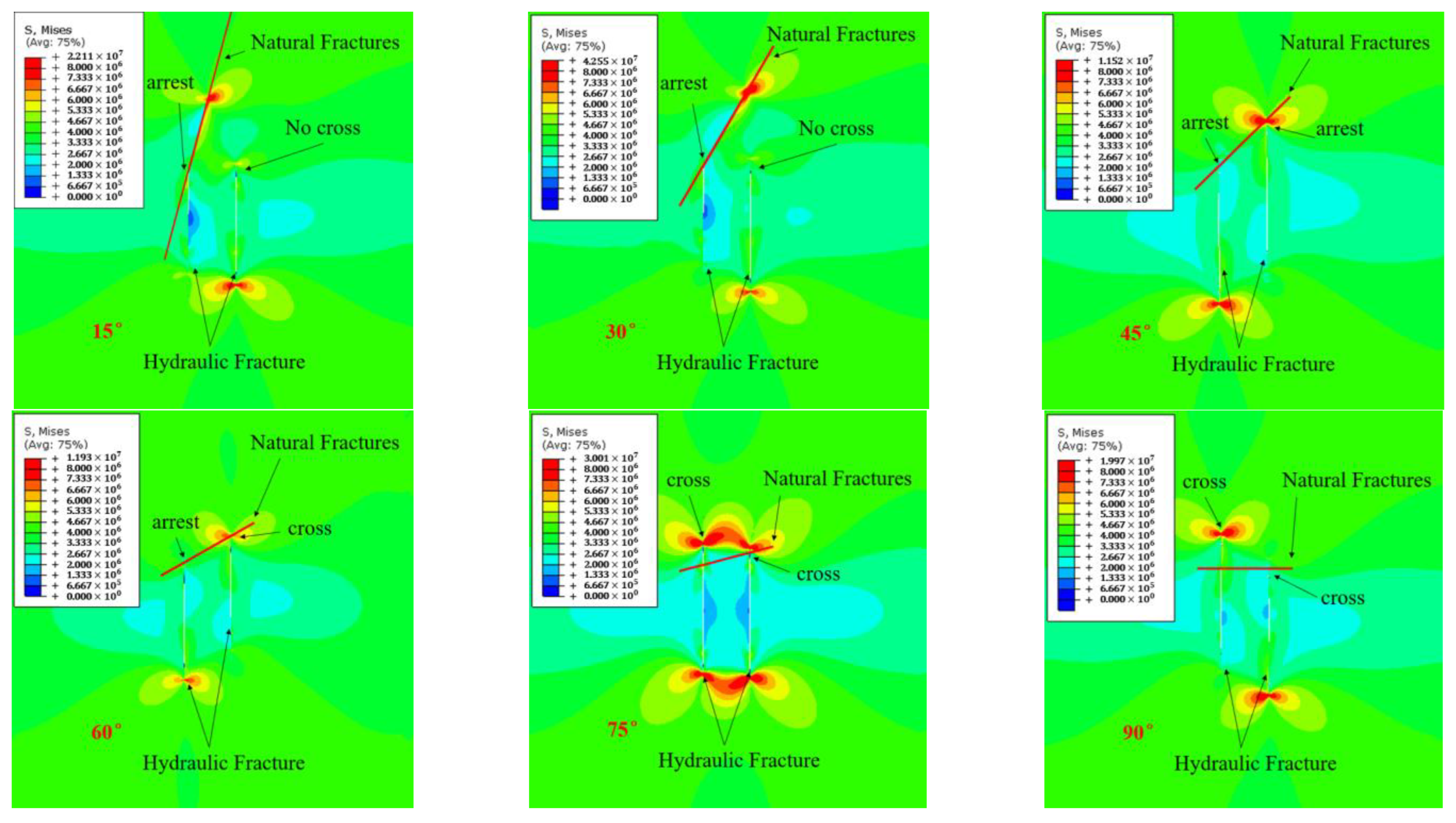
We analyzed the interference of multiple fractures when a single fracture exists in the reservoir, establishing a multiple fracture propagation model with fracture angles of 15°, 30°, 45°, 60°, 75°, and 90°, and analyzed the impact of natural fracture angles on the propagation of multiple fractures in horizontal wells. As shown in
Figure 11.
When the angle of the fracture is low, the natural fractures are close to 90° to the maximum horizontal principal stress direction, and they have a strong controllability over hydraulic fractures. In the initial stage, hydraulic fractures expand symmetrically to both sides. After encountering the natural fracture on the left side, they are captured by the natural fracture and expand upwards along the direction of the natural fracture, with longitudinal fractures gradually closing [
23]. The right hydraulic fracture extends in the opposite direction. Small areas of undisplaced stratigraphy exist between seams.
When the angle of the fracture is moderate, the angle between the natural fractures and the direction of the maximum horizontal principal stress gradually decreases, resulting in a gradual decrease in the controllability of natural fractures over hydraulic fractures. The propagation patterns of hydraulic fractures on both sides are essentially the same but in opposite directions. At 45°, the hydraulic fracture on the right side is captured by the natural fracture and propagates upwards along the direction of the natural fracture. After the left hydraulic fracture intersects the natural fracture, the natural fracture is opened first, with some of the fracturing fluid turning toward the natural fracture, but expanding mainly downward. However, at 60°, the hydraulic fracture on the right side completely intersects the natural fracture. With the increase in angle, the opening degree of natural fractures decreases, and the ability to divert the fracturing fluid weakens, resulting in a reduction in stress concentration areas near the natural fractures.
When the angle of the fracture is high, the angle between the natural fractures and the direction of the maximum horizontal principal stress decreases, resulting in a weaker controllability of natural fractures over hydraulic fractures. After encountering the natural fracture, the hydraulic fracture will penetrate through the natural fracture and propagate along the direction of the maximum horizontal principal stress. The hydraulic fracture on the left side will continue to propagate upwards along the direction of the maximum stress, while the hydraulic fracture on the right side will propagate downwards.
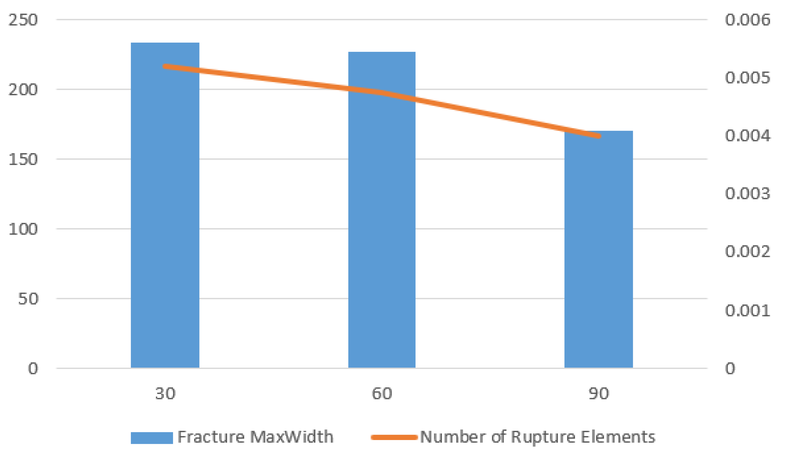
Based on
Figure 12, it can be seen that as the angle decreases, both the number of fractured elements and the maximum width of fractures increase. A larger angle makes it easier for hydraulic fractures to penetrate through natural fractures, and most of the fracturing fluid is used to continue the propagation of hydraulic fractures. When the angle decreases, some steering influence on the fracturing fluid moves the injection of the fracturing fluid into the natural fracture; at this point, the normal pressure of the fracturing fluid increases and the tangential pressure decreases. The injection of fracturing fluid increases the pressure within the fractures and applies it to the surface of the crack; stress is more concentrated on both sides of the fracture, leading to an increase in fracture width [
24].
4.4. Impact of the Number of Fracture Sets
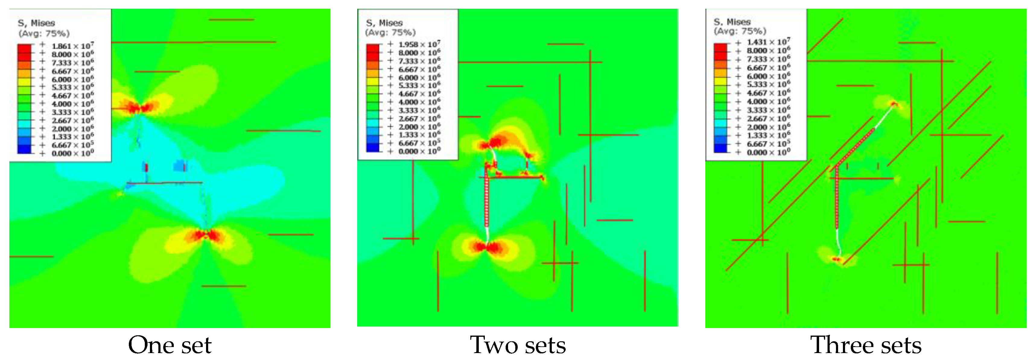
We analyzed the impact of natural fractures with different numbers of fracture sets in the reservoir, studying the influence of natural fractures on the propagation of multiple fractures in horizontal wells under different angles and overlaying conditions by establishing three different sets of natural fractures at 90°, 0°, and 45°. As shown in
Figure 13.
When there is only one set of natural fractures with a 90° angle, the two hydraulic fractures primarily propagate in opposite directions. In the initial stage of hydraulic fracture propagation, the fractures mainly expand symmetrically along the direction of the maximum principal stress. As the fractures continue to propagate, when the hydraulic fractures encounter the natural fractures, both hydraulic fractures partially propagate along the direction of the natural fractures [
25].
When there is one set of natural fractures with a 90° angle and one set of natural fractures with a 0° angle, the hydraulic fractures primarily propagate along the direction of the maximum stress in the initial stage of expansion. When they intersect with the natural fractures, they are captured by the natural fractures. The hydraulic fractures mainly propagate along the direction of the natural fractures at 0°, and the complexity of fracture development is higher compared to a single set of natural fractures.
When there is one set of natural fractures with a 90° angle, one set with a 0° angle, and one set with a 45° angle, during the initial stage of hydraulic fracture propagation, the fractures primarily expand along the direction of the maximum horizontal principal stress. When the hydraulic fractures intersect with the natural fractures, they propagate in different directions, forming multiple fracture branches.

 ,
, 


