
Measuring Device Detecting Impact Forces on Impact Rollers

Department of Machine and Industrial Design, Faculty of Mechanical Engineering, VSB-Technical University of Ostrava, 17. Listopadu 2172/15, 708 00 Ostrava, Czech Republic
*
Author to whom correspondence should be addressed.
Processes 2024, 12(5), 850; https://doi.org/10.3390/pr12050850
Submission received: 27 February 2024
/
Revised: 9 April 2024
/
Accepted: 20 April 2024
/
Published: 23 April 2024
(This article belongs to the Section Manufacturing Processes and Systems)
Abstract
:This paper presents laboratory devices on which measurements were carried out to prove the validity of the assumption about the reduction in vibrations transmitted to the conveyor belt structure generated by the impact forces of falling material grains in the places of transfer or on the hoppers of conveyor belts. In order to limit damage to the conveyor belts caused by the impact of the sharp edges of material grains, conveyor belts are supported by impact rollers or impact rubber rods. A special modification of the fixed conveyor idler is presented, which consists of inserting plastic brackets into the structurally modified roller axle holders of the fixed conveyor idler. Measurements showed that the specially modified fixed conveyor idler resulted in a higher damping of up to 15% of the impact forces of the falling weight on the rubberized hoop of the impact roller shell compared to the conventional fixed conveyor idler design. Measurements carried out show that the effective vibration velocity values detected at the points where the impact roller axis fits into the fixed roller table holder are higher than when using plastic brackets, up to 6% for a 108-mm-diameter roller, compared to steel impact roller brackets.
1. Introduction
When transporting bulk materials by belt conveyors, it is often necessary to transfer the transported material from one belt conveyor to another. This workspace, where material grains (carried on the surface of the conveyor belt) are thrown obliquely as they pass in front of the end drum [1] of the conveyor belt onto the conveyor belt of the following conveyor belt, is called the “transfer station”, see Figure 1a, and can be straight or angled (Figure 1b). The conveyed material can also be fed onto the working surface of the conveyor belt via a hopper, as shown in Figure 1c.
Material grains of mass m [kg] with sharp edges falling from a height h [m] onto the working surface of the conveyor belt at the point of the transfer or hopper damage the conveyor belt due to their impact energy [2,3,4]. Repeated impacts of material grains can severely damage the covering rubber layer as well as the supporting frame of the conveyor belt and lead to its destruction [5,6,7]. One of the possible solutions, which is used in practice to limit the high values of the dynamic effects of falling material grains on the conveyor belt, is the use of so-called “impact rollers” at the filling points (the hopper) and the transfer points of conveyor belts.
In the article [8], K. Hicke et al. describe the acoustic monitoring of the rollers’ condition in industrial conveyor belt installations.
In the article [9] by the author Y. Liu et al., the monitoring of the sound of transport roller bearings is described.
Impact rollers are one of the auxiliary elements used for belt conveyors. In the load-bearing run of the conveyor belt, one (a straight conveyor idler bench) or more (a trough conveyor idler bench) conveyor idlers are used to support the conveyor belt. The specific function of the impact rollers is to provide optimum support for the conveyor belt at loading points and transfer points where the conveyor belt is subjected to significant impact forces.
In the article [10], the failures of a hundred bearings of conveyor belt rollers are analyzed. This article specifies the possible causes of damage to the conveyor roller bearings and proposes measures to eliminate them.
The impact roller is generally similar in design to other types of transport rollers. It differs in that it is equipped with a central member, i.e., a reduced-diameter steel casing on which a grooved rubber hoop with the required thickness is fitted. The rubber hoop is usually designed as a set of concentric rings that form a grooved surface on the outer shell of the impact rollers. The grooved rubber hoop offers excellent impact resistance with the ability to absorb the forces induced by the impact of material grains on the working surface of the conveyor belt at the filling and transfer points of the conveyor belt, compared to conventional (steel or plastic) conveyor roller casings.
In the paper [11], a machine-learning method for diagnosing the failures of conveyor belt rollers is presented. The method consists of applying a wavelet transform to the measured vibration signals, extracting features from the processed signals, and applying the Gradient Boosting method to classify the state of the idlers.
Impact rollers can be inserted into standard conveyor idlers (Figure 2a) or into the suspended carrying idlers (Figure 2b) of the conveyor belt. A selected number of impact rollers (spacing and [m], see Figure 2c) is designed so that these rollers absorb as much of the impact force as possible at the transfer points and prevent accelerated wear of the conveyor belt. The spacing of the impact rollers is, at the filling and transfer points of the belt conveyors, smaller than the spacing of the conventional transport rollers mounted in the conveyor belt load-bearing run.
Impact rollers, like conveyor rollers, produce vibrations that become more intense as the circumferential speed of the rotating roller shell increases. Vibrations and the noise [12,13] of the conveyor rollers are an undesirable by-product of the continuous conveyor belt operation.
H. Shiri et al., in the article [14], define that due to the number of idlers to be monitored, the size of the belt transporter, and the accident risk when servicing with rotating parts and moving belts, monitoring of all idlers (i.e., using vibration sensors) is impractical regarding scale. Hence, an inspection robot is proposed to capture acoustic signals instead of vibrations, which are commonly used in condition monitoring.
The measurements of the jacket’s vibrations of rollers installed on a laboratory stand were made in the article [15] by G. Peruń. It also presents the results of the study, which have on aim a non–invasive qualification of the technical state of rollers in the belt conveyor after a certain time of exploitation.
In the article [16], F. Alharbi et al. present a review of vibration and acoustic signal-based fault detection for belt conveyor idlers using ML models. It also talks about key steps in the approaches, such as signal processing, data collection, feature extraction and selection, and ML model construction.
In the article [17], the parameters that represent the technical condition of tension rollers for the purpose of condition monitoring are presented. This article describes a test device for monitoring the vibration and temperature of belt conveyor tension rollers.
Belt conveyors, especially of high lengths, are equipped with a large number of conveyor rollers, which must be monitored to prevent damage, especially to their bearings. Damage to the bearings leads to an increase in the motion resistance of the conveyor belt and also to the possibility of stopping the rotation of the roller casing. When the bearings of the conveyor roller are damaged and the rotation of the roller casing stops, the non-moving surface of the roller casing wears out due to friction in the contact surface of the moving conveyor belt. This can lead to mechanical damage, i.e., a longitudinal cutting of the cover or even the load-bearing layer, of the conveyor belt. It is therefore necessary to monitor the technical condition of the roller bearings by machine vision [18] or by using sensors with measuring devices [19].
Visual and acoustic methods are commonly used to identify faulty or defective guide bearings, as shown in [20]. The article describes the use of an accelerometer that moves with the belt and at the same time monitors the condition of all bearings.
The article [21] presents the detection of damage to rollers based on the transverse vibration signal measured on the conveyor belt. A solution was proposed for a wireless measuring device that moves with the conveyor belt along the route, which records the signal of transverse vibrations of the belt.
The design modification of the fixed conveyor idler is presented in this article, which solves the installation of plastic brackets in the places where the end parts of the conveyor roller axles are inserted into the notches created in the steel trestle of the traditional fixed conveyor idler.
The motivation to solve the described problem is the necessity of distributors or contractors of machinery, which includes belt conveyors, and to introduce safe products for the market in the European Union (Czech Republic). According to Directive 2006/42/EC (Government Regulation No. 176/2008 Coll.), the distributor or contractor must inform the user in the instruction manual about the noise and vibration levels caused by the machinery.
Vibration and noise arising during the manipulation of material is due to the result of several factors: design error; contact between roller and structure; material used, rubber rollers produce lower vibrations than steel; and incorrect calibration of the roller rotation, which can cause strong vibrations and lead to the destruction of the roller and working environment. Lastly, very humid or dusty areas can be the reason for rapid damage of roller casing or bearings.
2. Materials and Methods
2.1. Laboratory Device Detecting the Forces of Grains Impacting the Impact Roller
The laboratory apparatus, see Figure 3, was designed for a practical verification of the theoretical assumption that the vibrations transmitted to the conveyor belt load-bearing run, as well as the dynamic effects of falling material grains from a height of h [m] on the working surface of the conveyor belt at the point of transfer, will be of a lower magnitude when using plastic brackets placed in the trestles of the fixed conveyor idler into which the flattened end parts of the axle of the impact roller are fitted.
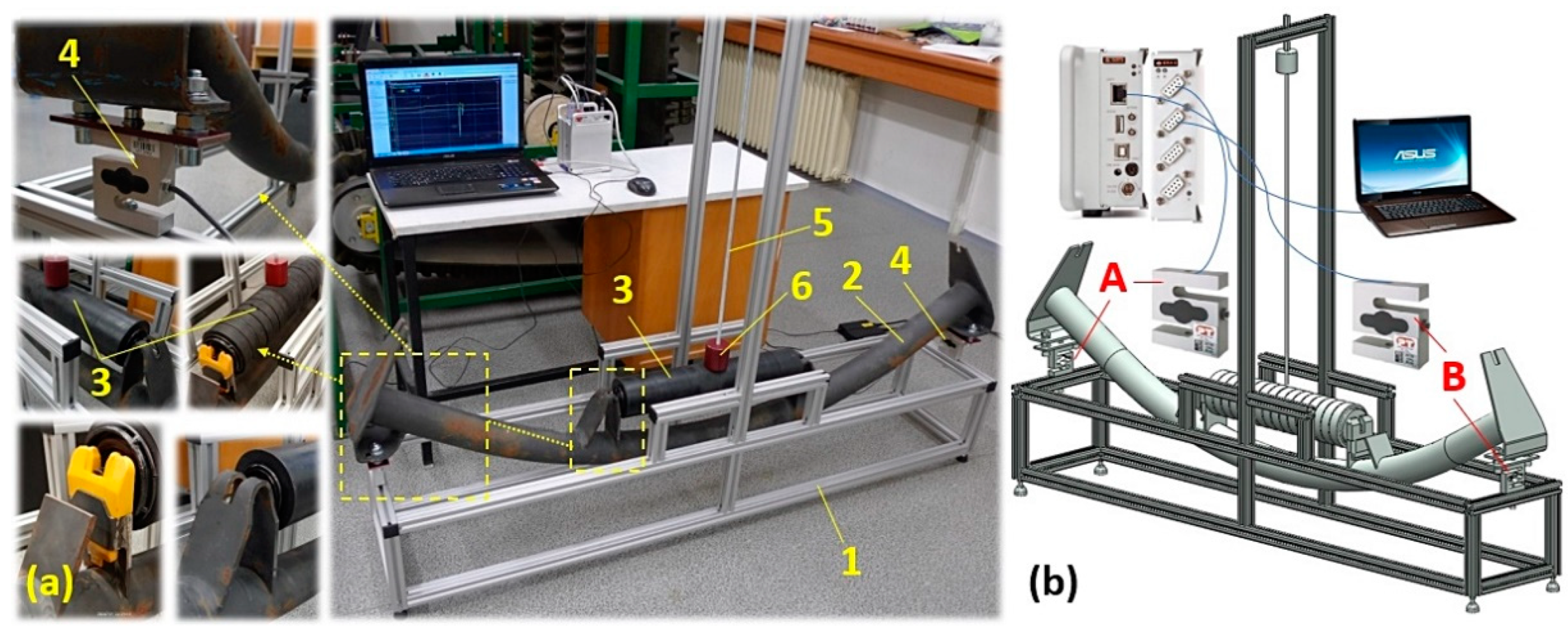
The laboratory equipment consists of a frame 1, made of aluminum profiles with a cross dimension of 30 × 30 mm, with a manufacturing designation of MI 30 × 30 B8 [22]. The fixed conveyor idler bench 2 of the conventional or special design was mounted on two strain gauge force transducers AST-250 kg 4 [23], which are attached to the lower part of the aluminum frame 1. A weight 6 is lowered by free fall from a height H [m] onto the impact roller 3, which is guided onto the impact roller by a rod 5 with a circular cross-section.
The end flattened parts of the axis of the impact roller 1 are inserted into the trestle notches of the fixed conveyor idler 2, see Figure 4a, with a traditional design. In the case of a special fixed conveyor idler, plastic brackets 4 are inserted into the structurally modified trestles 3 into which the end parts of the impact roller axle 1 are inserted, see Figure 4b.
The aim of the experimental measurements carried out on the laboratory equipment (see Figure 3) was to verify whether the plastic brackets, mounted in the structurally modified trestles of the fixed conveyor idler (see Figure 4b) can limit the magnitude of the dynamic force exerted by the impact of two bodies (the weight and the rubberized shell of the impact roller) transmitted to the conveyor belt load-bearing run. The dynamic force is generated by an incident weight 6 f mass mz [kg] from height H [m] on the rubber coating of the casing of the impact roller 3.
A verification of the damping assumption was carried out by laboratory tests as follows: weights 1 with the mass mz [kg] were freely dropped from a known height H [m] onto the rubberized casing of the impact roller 2, see Figure 5. At the moment of the impact of the weight, moving with velocity vz = (2·g·H)1/2 [m·s−1] on the rubber surface of the impact roller, the potential energy of the weight was transferred through the end parts of the axis of the impact roller to the fixed conveyor idler 3. The dynamic forces acting in the end parts of the fixed conveyor idler (as the response to the impact of the falling weight at vz [m·s−1] on the surface of the impacting roller) were detected by strain gauge force transducer 4. Excited signals in the “mV” of deformed strain gauges of strain gauge force transducers 4 were recorded by the strain gauge DS NET 5 [24] and graphically displayed on the PC monitor 6 (ASUS K72JR-TY131) in the DEWESoft X2 SP5 software environment.
2.2. Laboratory Device for Detecting the Vibration of a Rotating Impact Roller
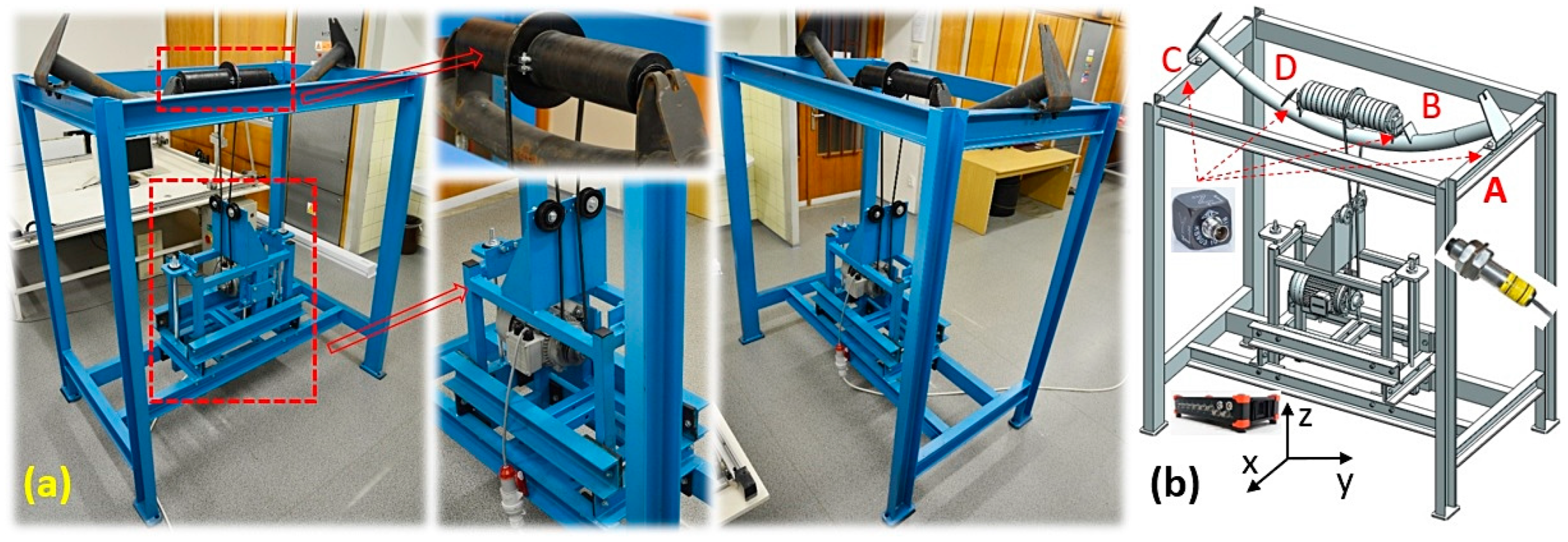
On the laboratory device, see Figure 6, the vibrations (in three planes perpendicular to each other) of a rotating rubberized impact roller casing mounted in a conventional (Figure 4a) or special (Figure 4b) trestle conveyor idler were tested.
The laboratory device designed to measure the vibration of the rotating casing of an impact roller, see Figure 6, consists of a welded steel frame 1, to which a fixed conveyor idler is attached by screw connections 2. A split V-belt pulley 4 is clamped against the outer surface of the rubberized casing of the impact roller 3. The V-belt 5 (type SPZ 2500 Lw 9.7 × 2513 La L = L), guided through the groove of the drive pulley mounted on the shaft of the electric motor 6, spins the impact roller 3 to reach the desired speed of nr [s−1]. Speed ne [s−1] of the electromotor 6 is controlled by a frequency converter (type YASKAWA VS-606 V7) [25]. Applying the necessary pressure to the V-belt 5 to the driven and driving V-belt pulley is done using a tensioning device 7.
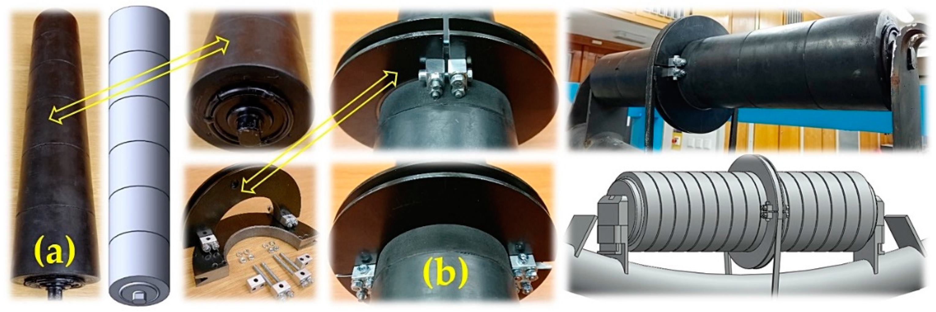
The objective was to achieve rotation at the desired circumferential velocity vr [m·s−1] of the impact roller during the experimental measurements of the vibration of the rotating shell of the impact roller on a laboratory device (Figure 6), and it was carried out in the Laboratory of Research and Testing, Department of Machine and Industrial Design, Faculty of Mechanical Engineering, VSB-Technical University of Ostrava. Due to the inaccuracy of the outer dimension of the rubber coating, it was not possible to mount a pulley on the impact roller similar to the use of conveyor rollers with a steel or plastic casing [26,27]. For impact rollers of 108 mm and 89 mm diameter, pulleys for V-belts with an outer diameter of 174 mm and 154 mm and a width of 16 mm were purchased from Pikron s.r.o. [28]. These pulleys were cut into two equal parts 1, see Figure 7a. Four holes with a diameter of 4.2 mm were drilled in the face of each part of the cut pulley. Using bolted connections 2, brackets 3 were attached to the front faces of parts 1, see Figure 7b.
The spinning of the impact rollers, fixed in the fixed conveyor idler of the laboratory device (Figure 6), was done by mounting both parts of the pulley 1 (see Figure 7) on the outer diameter of the rubber coating of the impact roller. Both parts of the pulley 1 were mechanically connected using bolted connections 4.
For a 154 mm (174 mm) outer diameter pulley mounted on an 89 mm (108 mm) diameter impact roller, the calculated diameter is Dw = 150 mm (170 mm).
The vibrations of the impact rollers with outer diameters Dr = 89 mm, 108 mm, and 133 mm were measured on the laboratory device (Figure 6) at the circumferential speeds of the impact roller casings vr = 3.15, 2.5 and 1.25 m·s−1.
Due to the different calculated diameters of the pulleys Dw [m], it was necessary to correct the speed nr [s−1] of the impact roller casings by changing the speed of the driving electric motor ne [s−1] using a Yaskawa VS-606 V7 frequency converter [25]. The torque is transferred from the drive pulley of the calculated diameter dw = 85 mm (which is mounted on the shaft of the drive electric motor) to the driven pulley of the calculated diameter Dw [m], which is mounted on the impact roller casing, using a V-belt.
According to relation (1), it is possible to determine the theoretical magnitude of the frequency fi [Hz], see Table 1, which is set on the frequency converter at the moment when the impact roller casing is rotating at the circumferential velocity vr [m·s−1], assuming that iw = Dw/dw [m].
where f [Hz]—the frequency (in Europe, a unified distribution grid of 400/230V with a frequency of 50 Hz is used); vr [m·s−1]—circumferential velocity of the impact roller casing; iw [-]—the ratio of the pulley diameter Dw [m] to the drive pulley diameter dw [m]; Dr [m]—the impact roller diameter; ne [s−1]—the rotation speed of the electric motor.
The rotational speed nr [s−1] of the impact roller with a casing moving at a circumferential velocity vr [m·s−1] was determined according to relation (2).
where vr [m·s−1]—circumferential velocity of the impact roller casing; Dr [m]—the impact roller diameter.
The aim of the experimental measurements carried out on the laboratory equipment (see Figure 6) was to verify whether the plastic brackets, fixed in the structurally modified trestles of the fixed conveyor idler (see Figure 4b) are able to limit the magnitude of the vibrations excited by the rotation of the rubberized casing of the impact roller by the speed of nr [s−1].
Verification of the vibration magnitude limitation assumption was carried out by laboratory tests as follows: vibrations (in three mutually perpendicular planes) caused by the rubberized impact roller casing 1 rotating at circumferential speed vr [m·s−1], see Figure 8, were detected by two acceleration sensors 2 PCE KS903.10 [29]. The speed of the impact roller 1 was taken by an optical laser sensor 3 DS-TACHO-3 [30]. The signals from the acceleration sensor 2 were recorded during the experimental measurements with the Dewesoft SIRIUSi-HS 6xACC, 2xACC+ 4 [31]. The time records of the measured values were transformed by the measuring apparatus into the effective values of the broadband velocity value v(*) [mm·s−1] (where * defines the direction of the “x”, “y”, or “z” axis of the coordinate system) in the range of 10 ÷ 1 · 104 Hz (this frequency range is applied to the ISO 10816-3 standard) [32]). The effective speed value v(*)RMS(fi) [m·s−1] periodic waveforms were displayed on a PC monitor using DEWESoft X measurement software.
2.3. Impact Rollers
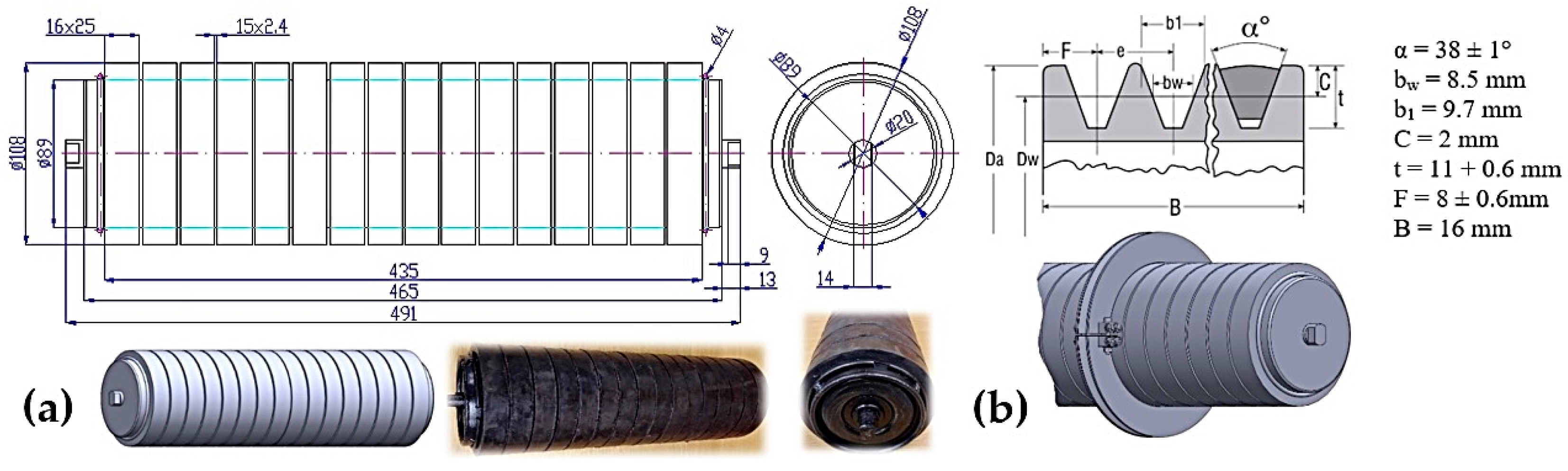
For the impact roller with outer diameter Dr = 108 mm, supplied to the market by DUBA-DP s.r.o., used for experimental measurements on laboratory equipment, a 9.5-mm-thick rubber layer is installed on the 89-mm-diameter steel casing, see Figure 9a.
For the 89-mm-outer-diameter impact roller (Figure 10a), a 19-mm-thick rubber layer is applied on the 51-mm-diameter steel casing.
3. Results
The experimental measurements under identical technical conditions on laboratory equipment were carried out on a fixed conveyor idler of a conventional or special design and for two impact rollers with diameters of 89 mm and 108 mm.
The first laboratory device was used to measure the dynamic forces generated by the impact of a weight hitting the rubberized hoop of the impact roller casing. The second laboratory device was used to measure vibrations in three mutually perpendicular planes of the impact roller rotating casing.
3.1. Measurement of the Force in the Supports of a Conveyor Idler for a Weight Falling on the Casing of an Impact Roller: Placement of the Roller Axle in the Plastic Brackets
Measurements of the magnitude of the forces were carried out on laboratory equipment at the points of the mechanical attachment of the supports for the specially designed conveyor idler fixed roller table to the aluminum frame. For the impacts of the weight hitting the rubberized hoop of the impact roller, see Figure 11.
Table 2 presents measured force waveforms F(Dr)j,i [N], which are generated by the impact of a weight with mass mz = 1 kg falling from the height of H = 787 mm on the rubberized casing of the impact roller with the outer diameter of Dr = 89 mm. The two flattened end parts (Figure 9a) of the impact roller were mounted in plastic brackets, embedded in the structurally modified trestles of the fixed conveyor idler (Figure 4b).
Table 2 shows the calculated arithmetic mean of all i = 5 measured force values Fd(Dr)j [N], including the limit measurement error κα,j [N] for the selected risk Student’s distribution α = 5% and Student’s coefficient tα,i = 2.78 [33,34].
Figure 12 presents a graphical time record of two measured forces detected by strain gauge force transducers at measuring points A and B of a fixed conveyor idler. For the measurements taken on laboratory equipment used to measure impact forces, see Figure 11. Figure 12a presents the measured forces F0(Dr)j,i [N]; these forces define the weight of the relative part of the impact roller and the fixed conveyor idler at the moment when the weight is not in contact with the impact roller. Figure 12b presents the measured forces F(Dr)j,i [N]. These forces define the maximum values of the forces that were detected at the moment of the impact of the weight on the rubberized hoop of the impact roller casing.
Table 3 presents measured force waveforms F(Dr)j,i [N], which are generated by the impact of a weight with mass mz = 1 kg falling from the height of H = 778 mm on the rubberized casing of the impact roller with the outer diameter of Dr = 108 mm.
Figure 13 shows a graphical time record of two measured forces detected by strain gauge force transducers at measuring points A and B of a fixed conveyor idler on a laboratory device used to measure impact forces, which was fitted with a 108-mm-diameter impact roller.
3.2. Measurement of the Force in the Supports of a Fixed Conveyor Idler of a Weight Falling on the Conveyor Roller Casing: Placement of the Roller Axle in the Steel Trestles
Table 4 presents the measured force waveforms generated by the impact of a weight of mass mz = 1 kg from a height of H = 787 mm on the rubber hoop of the impact roller casing with the outer diameter of Dr = 89 mm. Both flattened end parts (Figure 9a) of the impact roller were placed in the grooves of the steel trestles on the fixed conveyor idler (Figure 4b).
Figure 14 shows a graphical time record of two measured forces detected by strain gauge force transducers at measuring points A and B of a fixed conveyor idler on a laboratory device used to measure impact forces, which was fitted with an 89-mm-diameter impact roller.
Table 5 presents measured force waveforms F(Dr)j,i [N], which were generated by the impact of a weight with mass mz = 1 kg falling from the height of H = 778 mm on the rubberized casing of the impact roller with the outer diameter of Dr = 108 mm.
Figure 15 shows a graphical time record of two measured forces detected by strain gauge force transducers at measuring points A and B of a fixed conveyor idler on a laboratory device used to measure impact forces, which was fitted with a 108-mm-diameter impact roller.
3.3. Vibration Measurement of the Rotating Rubberized Impact Roller Casing and Steel Roller Axle Bracket
The experimental measurement of vibration speeds v(*)RMS(fi) [mm·s−1] (3) for the rotating impact roller of diameter Dr [mm] was carried out on a laboratory machine, see Figure 16, under the same technical conditions on two types of fixed conveyor idler (the basic dimensions correspond to CSN ISO 1537 [30]), see Figure 4.
where v(t) [m·s−1]—the instantaneous speed; A [m]—the deflection; ω [rad·s−1]—the angular speed; and t [s]—the relevant time.
The experimental measurement of vibration speeds v(*)RMS(fi) [mm·s−1] was performed on a middle roller (horizontally mounted roller in a fixed conveyor idler), see Figure 4, laboratory device (Figure 6). An impact roller of a given diameter Dr [mm] fitted with a V-belt pulley, see Figure 7, was rotated by an SPZ V-belt type to the speed of nr [min−1] (see Table 6). Two acceleration sensors [7] detected the vibration of the rotating impact roller on the trestle (B or D) of the fixed conveyor idler, see Figure 16b, or on the top surface of the laboratory equipment frame (see point A or C).
Table 6 gives the effective vibration velocity values v(*)RMS(fi) [mm·s−1], as read from the DEWESoft X measuring software, for the measured vibration values of an 89-mm-diameter impact roller at measuring points A and B of a fixed roller table with steel trestles (Figure 4a) of the laboratory device (Figure 16a).
Figure 17 indicates the measured effective vibration velocity values v(*)RMS(31.5) [mm·s−1] in the “x”, “y”, and “z” axes of the selected coordinate system at the circumferential velocity vr = 2.5 m·s−1 for an impact roller with a diameter of 89 mm, placed in the steel trestle of the fixed conveyor idler (Table 7, Table 8 and Table 9).
3.4. Vibration Measurement of the Rotating Rubberized Impact Roller Casing, Plastic Roller Axle Bracket
Table 10 gives the effective vibration velocity values v(*)RMS(fi) [mm·s−1], read from the DEWESoft X measuring software, for the measured vibration values of an 89-mm-diameter impact roller at measuring points A and B of a fixed conveyor idler of special design (Figure 4b) on the laboratory machine (Figure 16a).
Figure 21 shows the measured effective vibration velocity values v(*)RMS(31.5) [mm·s−1] in the “x”, “y”, and “z” axes of the selected coordinate system at the circumferential velocity vr = 2.5 m·s−1 of an impact roller with a diameter of 89 mm, mounted in the plastic brackets of engineered steel trestles in a fixed conveyor idler (Table 11, Table 12 and Table 13).
4. Discussion
The evaluated measurements of the forces, given in Section 3, generated by the impact of the weight hitting the impact roller with a ϕ89 mm diameter show that (for i = 5 repeated measurements under the same technical conditions) the mean value of the measured force F(Dr)j,i [N] at measuring point A, and also at measuring point B, (see Figure 11b) is lower when the axle of the impact roller is placed in the plastic brackets.
Table 2 shows for measuring points A and B, on a fixed conveyor idler with rubber impact roller axle brackets of ϕ89 mm, the magnitude of the calculated dynamic force F(89)A,p = 83.8 ± 1.5 N and F(89)B,p = 85.5 ± 2.3 N.
According to Table 4, for the measuring points A and B, the dynamic force F(89)A,s = 86.5 ± 1.4 N and F(89)B,s = 89.0 ± 1.7 N were calculated for the fixed conveyor idler with steel impact roller axle brackets of ϕ89 mm.
For the ϕ89 mm impact roller, the size of the force F(89)A,p [N] reaches 98.0% of the force F(89)A,s [N] and the size of F(89)B,p [N] force reaches a magnitude of 97.2% of the force F(89)B,p [N].
At both measuring point C and measuring point D (see Figure 11b), the magnitudes of the forces generated by the impact of the weight hitting the impact roller of ϕ89 mm are also lower when the axle of the impact roller is mounted in plastic brackets.
By evaluating the measurements of the forces generated by the impact of the weights hitting the impact roller of ϕ108 mm, see Section 3 (for I = 5 repeated measurements under the same technical conditions), it can be concluded that the mean values of the measured forces F(Dr)j,i [N] at measuring point A and at measuring point B (see Figure 11b) are also lower in the case of the placement of the axle of the impact roller placed in the plastic brackets.
Table 4 shows for measuring points A and B, on a fixed conveyor idler with rubber brackets for the axle of the impact roller of ϕ89 mm, the magnitude of the calculated dynamic force F(108)A,p = 60.7 ± 10.0 N a F(108)B,p = 62.2 ± 9.6 N.
According to Table 5, there are the calculated dynamic forces F(108)A,s = 72.4 ± 6.5 N and F(108)B,s = 72.9 ± 4.6 N for measuring points A and B on a fixed conveyor idler with steel brackets for the axle of the impact roller of ϕ89.
For the ϕ108 mm impact roller, the magnitude of the force F(108)A,p [N] reaches 83.8% of the force F(108)A,s [N] and the magnitude of the force F(108)B,p [N] reaches 85.3% of the force F(108)B,s [N].
It is advantageous to install plastic holders in engineered steel trestles that are welded to the circular cross-section tube of fixed conveyor idlers, as they can dampen the magnitude of impact forces generated at the transfer points of the conveyor belt. The impact of material grains thrown diagonally over the edge of the drum from the first conveyor belt onto the belt of the second conveyor causes impact forces of high magnitudes. The magnitude of the force impulse depends on the magnitude of the force and the time over which the force was applied. It is known that the impulse of the force is equal to the change in the momentum of the body; therefore, if the weight of the falling grain acts for a longer time (a deformation of the rubber brackets to which the ends of the impact roller axle are attached is higher than the deformation of the steel trestles), the impact force has a lower magnitude [35].
The realized vibration measurements, see Section 3.3 and Section 3.4, of the rotating rubberized casing (ϕ89 mm and ϕ108 mm) impact roller on the laboratory device (see Figure 16) have not been demonstrated. As stated in [1,2], the plastic brackets limit the amount of vibration (excited by the rotating casing of the conveyor roller) transferred by the support beam of a fixed conveyor idler to the steel frame of a laboratory device that simulates the conveyor belt run.
Similar to [1], higher effective vibration velocity values in each of the “x”, “y”, and “z” coordinate axes were measured on the laboratory equipment for higher impact roller casing speeds, see Table 6, Table 7, Table 8, Table 9, Table 10, Table 11, Table 12 and Table 13.
The measured effective vibration velocity values in the vertical direction (z-axis of the coordinate system) at measuring points B and D (see Figure 25) are higher if the axle of the impact roller of ϕ89 mm and the impact roller of ϕ108 mm are placed in plastic brackets.
It can be seen from Table 6 and Table 10 that the vibration v(z)RMS(31.38) = 1.26 mm·s−1 (Figure 25) in the case of mounting the impact roller axle in plastic brackets (Figure 4b) is 2.8 times (by 280%) higher at measuring point B than the vibration v(z)RMS(31.55) = 0.45 mm·s−1 corresponding to mounting the impact roller axle at measuring point B in a steel bracket (Figure 4a).
From Table 7 and Table 11, it can be expressed that the vibration v(z)RMS(31.36) = 1.18 mm·s−1 (Figure 25) in the case of mounting the axle of the impact roller in plastic brackets (Figure 4b) is 2.7 times (by 274%) higher at measuring point D than the vibration v(z)RMS(31.48) = 0.43 mm·s−1 corresponding to mounting the axle of the impact roller at measuring point D in a steel bracket (Figure 4a).
From Table 8 and Table 12, it can be expressed that the vibration v(z)RMS(29.84) = 1.14 mm·s−1 (Figure 26) in the case of mounting the axle of the impact roller of ϕ108 mm in plastic brackets (Figure 4b) is 1.3 times (by 134%) higher than the vibration at measurement point B v(z)RMS(29.98) = 0.85 mm·s−1 for the corresponding location of the axle of the impact roller at measuring point B in the steel bracket (Figure 4a).
Table 9 and Table 13 prove that the vibrations v(z)RMS(29.83) = 1.13 mm·s−1 (Figure 26) in the case of the axle of the impact roller of ϕ108 mm placed in the plastic brackets (Figure 4b) is 1.1 times (by 107%) higher at measuring point D than the vibrations v(z)RMS(30.00) = 1.06 mm·s−1 for the corresponding location of the axle of the impact roller at measuring point D in the steel bracket (Figure 4a).
The different results of the calculated effective vibration values (in the “z” axis of the coordinate system) of the impact rollers, with outer diameters of rubber hoops Dr [m] for circumferential velocities v = 1.25 ÷ 3.15 m·s−1, from conveyor rollers of identical diameters with plastic or steel casings [2] can be expressed by the fact that the rubber hoops applied on a steel casing are not of an identical outer diameter. The difference in the outer diameters of the partial rubber hoops (6 pcs for the impact roller of ϕ89 mm, 16 pcs for the impact roller of ϕ108 mm) can already be seen visually. For experimental vibration measurements of the impact rollers on laboratory equipment (Figure 16), it was not possible to use “pulley assemblies” [2], which have been used in the experimental vibration measurements of the conveyor rollers with plastic or steel casings. The impossibility of sliding the “pulley assembly” to the required distance on the outer diameter of the rubberized hoops on the side of the impact rollers led to the necessity of designing split pulleys, see Figure 7.
5. Conclusions
The current trend of the digitization of industry is called Industry 4.0, which aims to automate and digitize production processes and uses methods and tools to save time and money and adapt to the situation and operations of companies. The process of automation brings with it the introduction of new technologies, equipping machines with chips and sensors and controlling computers to remotely monitor and control production processes. Through IoT technologies, data from various sensors and gauges can be collected and shared for further use.
The plastic brackets embedded in the designed roller axle brackets can dampen vibrations transmitted to the conveyor belt structure. It is preferable to use these special fixed conveyor idlers along the length of the conveyor belt run, and less suitable to use them at transfer points and hoppers.
The vibration values of the conveyor rollers (for the steel or plastic casing of the conveyor roller) [27] and also impact rollers (see Section 3.1 and Section 3.2) show that the effective values of the vibration velocity increase with the increasing speed (circumferential speed) of the conveyor roller casings. This assumption is also confirmed in article [26].
Experimental measurements carried out on the first laboratory device (see Section 3.1 and Section 3.2) showed that the implemented plastic brackets for the axle of the conveyor rollers in the structurally modified steel trestles of the fixed conveyor idler have the ability to dampen the vibrations excited by the rotating casing of the conveyor roller. The plastic brackets fitted into the trestles of the fixed conveyor idler also allow the absorption of a part of the impact force of the falling material grains at the transfer points or on the hoppers of the conveyor belts.
The realized vibration measurements of the rotating rubberized casing (ϕ89 mm and ϕ108 mm) impact roller on the second laboratory device (see Section 3.3 and Section 3.4) have not been demonstrated, as stated in [1,2]. The plastic brackets limit the amount of vibration (excited by the rotating casing of the conveyor roller) transferred by the support beam of a fixed conveyor idler to the steel frame of a laboratory device that simulates the conveyor belt run.
This experimentally established conclusion can be explained by the fact that the individual rubber hoops of unequal outer diameters cause oscillations and vibrations due to the unbalanced mass during the rotation of the impact rollers. The vibrations are more intense at higher impact roller speeds, as the centrifugal force of the rotating unbalanced mass is known to be proportional to the square of the angular velocity.
Measurements carried out on the second laboratory device show that the effective vibration velocity values detected at the points where the impact roller axis fits into the fixed roller table holder, i.e., points B and D, are higher than when using plastic brackets, up to 6% for a 108-mm-diameter roller, compared to steel impact roller brackets.
The plastic brackets embedded in the designed roller axle brackets can dampen vibrations transmitted to the conveyor belt structure. It is preferable to use these special fixed conveyor idlers along the length of the conveyor belt run, and less suitable to use them at transfer points and hoppers.
Author Contributions
Conceptualization, L.H. and Š.P.; methodology, L.H.; software, Š.P.; validation, E.N., T.M. and D.K.; formal analysis, L.H.; investigation, L.H.; resources, D.K.; data curation, E.N.; writing—original draft preparation, L.H.; writing—review and editing, L.H.; visualization, L.H. and E.N.; supervision, T.M.; project administration, L.H.; funding acquisition, L.H. All authors have read and agreed to the published version of the manuscript.
Funding
This research was funded by “Research and innovation of modern processes and technologies in industrial practice”, grant number “SP2024/001” and was funded by MŠMT ČR (Ministry of education youth and sports).
Data Availability Statement
Measured data of force values Fd(Dr)j [N], listed from Table 2 to Table 5 and processed using DEWESoft® X2 SP5X software and measured data of effective vibration speed values v(*)RMS(fi) [mm·s−1], listed from Table 6, Table 7, Table 8, Table 9, Table 10, Table 11, Table 12 and Table 13 and processed using DEWESoft X software, can be sent in case of interest, by prior written agreement, in *.XLSX (Microsoft Excel) format.
Conflicts of Interest
The authors declare no conflict of interest. The funders had no role in the design of the study; in the collection, analyses, or interpretation of data; in the writing of the manuscript; or in the decision to publish the results.
References
- Rozbroj, J.; Necas, J.; Gelnar, D.; Hlosta, J.; Zegzulka, J. Validation of movement over a belt conveyor drum. Adv. Sci. Technol. Res. J. 2017, 11, 118–124. [Google Scholar] [CrossRef] [PubMed]
- Fedorko, G.; Molnar, V.; Grincova, A.; Dovica, M.; Toth, T.; Husakova, N.; Kelemen, M. Failure analysis of irreversible changes in the construction of rubber–textile conveyor belt damaged by sharp-edge material impact. Eng. Fail. Anal. 2014, 39, 135–148. [Google Scholar] [CrossRef]
- Andrejiova, M.; Grincova, A. Klasifikace poškození nárazem na pryžotextilním dopravním pásu metodou Naïve-Bayes. Wear 2018, 414, 59–67. [Google Scholar] [CrossRef]
- Fedorko, G.; Molnar, V.; Zivcak, J.; Dovica, M.; Husakova, N. Analýza poruch textilního pryžového dopravního pásu poškozeného dynamickým opotřebením. Analýza Selhání Tech. 2013, 28, 103–114. [Google Scholar]
- Andrejiova, M.; Grincova, A.; Marasova, D. Identification with machine learning techniques of a classification model for the degree of damage to rubber-textile conveyor belts with the aim to achieve sustainability. Eng. Fail. Anal. 2021, 127, 105564. [Google Scholar] [CrossRef]
- Alviari, L.P.; Anggamawarti, M.F.; Sanjiwani, Y.; Risonarta, V.Y. Classification of impact damage on a rubber-textile conveyor belt: A review. Int. J. Mech. Eng. Technol. Appl. 2020, 1, 21–27. [Google Scholar] [CrossRef]
- Bortnowski, P.; Kawalec, W.; Krol, R.; Ozdoba, M. Types and causes of damage to the conveyor belt–Review, classification and mutual relations. Eng. Fail. Anal. 2022, 140, 106520. [Google Scholar] [CrossRef]
- Hicke, K.; Hussels, M.T.; Eisermann, R.; Chruscicki, S.; Krebber, K. Distributed Fibre Optic Acoustic and Vibration Sensors for Industrial Monitoring Applications. In Proceedings of the AMA Conferences 2017 with SENSOR and IRS2, Nuremberg, Germany, 30 May–1 June 2017; 274-279; AMA Service GmbH: Nuremberg, Germany; pp. 274–279. [Google Scholar]
- Liu, Y.; Miao, C.; Li, X.; Ji, J.; Meng, D.; Wang, Y. A Dynamic Self-Attention-Based Fault Diagnosis Method for Belt Conveyor Idlers. Machines 2023, 11, 216. [Google Scholar] [CrossRef]
- Vasic, M.; Stojanovic, B.; Blagojevic, M. Failure analysis of idler roller bearings in belt conveyors. Eng. Fail. Anal. 2020, 117, 104898. [Google Scholar] [CrossRef]
- Soares, J.L.; Costa, T.B.; Moura, L.S.; Sousa, W.S.; Mesquita, A.L.; Mesquita, D.S. Machine Learning Based Fault Detection on Belt Conveyor Idlers. In Proceedings of the DINAME, Pirenópolis, Brazil, 26 February–3 March 2023. [Google Scholar]
- Gondek, H.; Kolman, J.; Bohac, D. Results of belt conveyors noise reduction with the construction of roller holders. Int. Multidiscip. Sci. GeoConf. SGEM 2022, 22, 369–376. [Google Scholar]
- Kolman, J.; Bohac, D. Noise reduction of belt conveyor tracks. Int. Multidiscip. Sci. GeoConf. SGEM 2020, 20, 195–202. [Google Scholar]
- Shiri, H.; Wodecki, J.; Ziętek, B.; Zimroz, R. Inspection robotic UGV platform and the procedure for an acoustic signal-based fault detection in belt conveyor idler. Energies 2021, 14, 7646. [Google Scholar] [CrossRef]
- Perun, G. Attempt to evaluate the technical condition of the rollers of the belt conveyor by vibration measurements. Vibroeng. Procedia 2014, 3, 296–299. [Google Scholar]
- Alharbi, F.; Luo, S.; Zhang, H.; Shaukat, K.; Yang, G.; Wheeler, C.A.; Chen, Z. A brief review of acoustic and vibration signal-based fault detection for belt conveyor idlers using machine learning models. Sensors 2023, 23, 1902. [Google Scholar] [CrossRef] [PubMed]
- Liu, X.; Pang, Y.; Lodewijks, G.; He, D. Experimental research on condition monitoring of belt conveyor idlers. Measurement 2018, 127, 277–282. [Google Scholar] [CrossRef]
- Ji, Y.; Ma, J.; Zhou, Z.; Li, J.; Song, L. Dynamic Yarn-Tension Detection Using Machine Vision Combined with a Tension Observer. Sensors 2023, 23, 3800. [Google Scholar] [CrossRef] [PubMed]
- Staab, H.; Botelho, E.; Lasko, D.T.; Shah, H.; Eakins, W.; Richter, U. A robotic vehicle system for conveyor inspection in mining. In Proceedings of the 2019 IEEE International Conference on Mechatronics (ICM), Ilmenau, Germany, 18–20 March 2019; Volume 1, pp. 352–357. [Google Scholar]
- Roos, W.A.; Heyns, P.S. In-belt vibration monitoring of conveyor belt idler bearings by using wavelet package decomposition and artificial intelligence. Int. J. Min. Miner. Eng. 2021, 12, 48–66. [Google Scholar] [CrossRef]
- Bortnowski, P.; Krol, R.; Ozdoba, M. Roller damage detection method based on the measurement of transverse vibrations of the conveyor belt. Eksploat. I Niezawodn. 2022, 24, 510–521. [Google Scholar] [CrossRef]
- Hliníkový Profil 30 × 30 B8. Available online: https://www.marek.eu/hlinikove-konstrukcni-profily-mi-system/serie-b/velikost-30-drazka-b8/37496/hlinikovy-profil-30x30-b8.html (accessed on 26 September 2021).
- AST Tenzometrický Snímač Síly. Available online: https://www.format1.cz/files/products_files/a/AST.pdf (accessed on 16 February 2023).
- Technical Reference Manual DS-NET. Available online: https://d36j349d8rqm96.cloudfront.net/3/6/Dewesoft-DS-NET-Manual-EN.pdf (accessed on 28 October 2023).
- VS-606V7 Series Instruction Manual. Available online: https://automasjonslab.files.wordpress.com/2018/09/yaskawa-607.pdf (accessed on 25 June 2020).
- Hrabovsky, L.; Pravda, S.; Sebesta, R.; Novakova, E.; Kurac, D. Detection of a Rotating Conveyor Roller Casing Vibrations on a Laboratory Machine. Symmetry 2023, 15, 1626. [Google Scholar] [CrossRef]
- Hrabovsky, L.; Novakova, E.; Pravda, S.; Kurac, D.; Machalek, T. The Reduction of Rotating Conveyor Roller Vibrations by the Use of Plastic Brackets. Machines 2023, 11, 1070. [Google Scholar] [CrossRef]
- Klínové Řemenice. Available online: https://www.pikron.cz/getmedia/0821cabe-83bf-41de-abbd-bdca4f34702d/PIKRON-klinove-remenice.pdf (accessed on 18 March 2023).
- Hand-Arm Acceleration Sensor KS903.10. Available online: https://www.pce-instruments.com/eu/pce-instruments-hand-arm-acceleration-sensor-ks903.10-det_5966162.htm (accessed on 8 December 2022).
- Instruction Manual ROLS/ROLS24 Remote Optical Laser Sensor. Available online: https://monarchserver.com/Files/pdf/1071-4851-118_ROLS_ROLS24_Manual.pdf (accessed on 3 July 2023).
- DEWESoft General Catalog. Available online: https://www.datocms-assets.com/53444/1667943193-dewesoft-product-catalog-en.pdf (accessed on 2 May 2021).
- ČSN ISO 10816-1; Mechanical Vibration—Evaluation of Machine Vibration by Measurements on non-Rotating Parts—Part 1: General Guidelines (In Czech: Vibrace—Hodnocení Vibrací Strojů na Základě Měření na Nerotujících Částech -Část 1: Všeobecné směrnice). Available online: https://www.technicke-normy-csn.cz/csn-iso-10816-1-011412-158753.html (accessed on 17 September 2022).
- Madr, V.; Knejzlik, J.; Kopecny, I.; Novotny, I. Fyzikální Měření (In English: Physical Measurement); SNTL: Prague, Czech Republic, 1991; p. 304. ISBN 80-03-00266-41. [Google Scholar]
- Michalik, P.; Dobransky, J.; Hrabovsky, L.; Petrus, M. Assessment of the manufacturing possibility of thin-walled robotic portals for conveyance workplaces. Advances in Science and Technology. Res. J. 2018, 12, 338–345. [Google Scholar]
- Wang, R.; Cheung, C.F.; Wang, C. Unsupervised Defect Segmentation in Selective Laser Melting. IEEE Trans. Instrum. Meas. 2023, 752. [Google Scholar] [CrossRef]
Figure 1.
(a) conveyor belt transfer, (b) angled station, (c) a hopper.

Figure 2.
Impact rollers installed at the conveyor idler (a) fixed, (b) suspended carrying idlers, (c) spacing a [m] of the impact rollers in the transfer area of the conveyor belt.
Figure 2.
Impact rollers installed at the conveyor idler (a) fixed, (b) suspended carrying idlers, (c) spacing a [m] of the impact rollers in the transfer area of the conveyor belt.

Figure 3.
Laboratory device (a) 3D model software SolidWorks Premium 2012x64 SP5.0, (b) 2D drawing by AutoCAD software ver. 2010. 1—aluminum frame, 2—fixed conveyor idler, 3—impact roller, 4—strain gauge force sensor, 5—guide rod, 6—weights.
Figure 3.
Laboratory device (a) 3D model software SolidWorks Premium 2012x64 SP5.0, (b) 2D drawing by AutoCAD software ver. 2010. 1—aluminum frame, 2—fixed conveyor idler, 3—impact roller, 4—strain gauge force sensor, 5—guide rod, 6—weights.

Figure 4.
Fixed conveyor idlers with a (a) conventional and (b) special design. 1—impact roller, 2—the trestle of the conventional conveyor idler, 3—the trestle of the special conveyor idler, 4—plastic brackets.
Figure 4.
Fixed conveyor idlers with a (a) conventional and (b) special design. 1—impact roller, 2—the trestle of the conventional conveyor idler, 3—the trestle of the special conveyor idler, 4—plastic brackets.

Figure 5.
Dynamic force detection measuring chain. 1—weights, 2—impact roller, 3—fixed conveyor idler, 4—strain gauge force transducer, 5—DS NET strain gauge apparatus, 6—PC with DEWESoft X2 SP5 software.
Figure 5.
Dynamic force detection measuring chain. 1—weights, 2—impact roller, 3—fixed conveyor idler, 4—strain gauge force transducer, 5—DS NET strain gauge apparatus, 6—PC with DEWESoft X2 SP5 software.

Figure 6.
Laboratory equipment for measuring the vibration of a rotating roller casing (a) 3D model—SolidWorks software, (b) 2D drawing—AutoCAD software. 1—steel frame, 2—fixed conveyor idler, 3—impact roller, 4—split V-belt pulley, 5—V-belt, 6—electric motor, 7—tensioning device.
Figure 6.
Laboratory equipment for measuring the vibration of a rotating roller casing (a) 3D model—SolidWorks software, (b) 2D drawing—AutoCAD software. 1—steel frame, 2—fixed conveyor idler, 3—impact roller, 4—split V-belt pulley, 5—V-belt, 6—electric motor, 7—tensioning device.

Figure 7.
Impact Roller V-belt ϕ89 mm (a) 2D drawing—AutoCAD software and 3D model—SolidWorks software, (b) console. 1—part of the V-belt pulley, 2—bolted connection, 3—console, 4—bolted connection.
Figure 7.
Impact Roller V-belt ϕ89 mm (a) 2D drawing—AutoCAD software and 3D model—SolidWorks software, (b) console. 1—part of the V-belt pulley, 2—bolted connection, 3—console, 4—bolted connection.

Figure 8.
Measurement chain for the vibration detection of the rotating impact roller casing. 1—impact roller, 2—acceleration sensor, 3—optical laser sensor, 4—strain gauge apparatus DEWESoft SIRIUSi-HS, 5—PC with DEWESoft X software.
Figure 8.
Measurement chain for the vibration detection of the rotating impact roller casing. 1—impact roller, 2—acceleration sensor, 3—optical laser sensor, 4—strain gauge apparatus DEWESoft SIRIUSi-HS, 5—PC with DEWESoft X software.

Figure 9.
Impact roller (a) with outer diameter 108 mm, (b) fitted with an outer diameter V-belt pulley at Da = 174 mm and calculated diameter of Dw = 170 mm.
Figure 9.
Impact roller (a) with outer diameter 108 mm, (b) fitted with an outer diameter V-belt pulley at Da = 174 mm and calculated diameter of Dw = 170 mm.

Figure 10.
(a) Rubberized impact roller with outer diameter of 89 mm, (b) V-belt pulley of calculated diameter Dw = 150 mm. The arrows refer to the impact roller and the pulley mounted on the right transport roller.
Figure 10.
(a) Rubberized impact roller with outer diameter of 89 mm, (b) V-belt pulley of calculated diameter Dw = 150 mm. The arrows refer to the impact roller and the pulley mounted on the right transport roller.

Figure 11.
(a) Laboratory equipment used to measure impact forces, (b) placement of strain gauge sensors at the measuring points A and B. 1—aluminum frame, 2—fixed conveyor idler, 3—impact roller, 4—strain gauge force sensor, 5—guide rod, 6—weights.
Figure 11.
(a) Laboratory equipment used to measure impact forces, (b) placement of strain gauge sensors at the measuring points A and B. 1—aluminum frame, 2—fixed conveyor idler, 3—impact roller, 4—strain gauge force sensor, 5—guide rod, 6—weights.

Figure 12.
(a) F0(89)j,4 [N] and (b) F(89)j,4 [N].

Figure 13.
(a) F0(108)j,4 [N] and (b) F(108)j,4 [N].

Figure 14.
(a) F0(89)j,4 [N] and (b) F(89)j,4 [N].

Figure 15.
(a) F0(108)j,4 [N] and (b) F(108)j,4 [N].

Figure 16.
(a) Laboratory equipment used to measure the vibration of conveyor rollers, (b) the placement of accelerometers in measuring points B and D on the fixed conveyor idler and in points A and C on the frame on the laboratory equipment.
Figure 16.
(a) Laboratory equipment used to measure the vibration of conveyor rollers, (b) the placement of accelerometers in measuring points B and D on the fixed conveyor idler and in points A and C on the frame on the laboratory equipment.

Figure 17.
Effective vibration speed values v(*)RMS(fi) [mm·s−1], the impact roller of ϕ89 mm, circumferential speed of the roller vr = 2.5 m·s−1, steel brackets, (a) measuring point A, (b) measuring point B.
Figure 17.
Effective vibration speed values v(*)RMS(fi) [mm·s−1], the impact roller of ϕ89 mm, circumferential speed of the roller vr = 2.5 m·s−1, steel brackets, (a) measuring point A, (b) measuring point B.

Figure 18.
Effective vibration speed values v(*)RMS(fi) [mm·s−1], the impact roller of ϕ89 mm, circumferential speed of the roller vr = 2.5 m·s−1, steel brackets, (a) measuring point C, (b) measuring point D.
Figure 18.
Effective vibration speed values v(*)RMS(fi) [mm·s−1], the impact roller of ϕ89 mm, circumferential speed of the roller vr = 2.5 m·s−1, steel brackets, (a) measuring point C, (b) measuring point D.

Figure 19.
Effective vibration speed values v(*)RMS(fi) [mm·s−1], the impact roller of ϕ108 mm, circumferential speed of the roller vr = 2.5 m·s−1, steel brackets, (a) measuring point A, (b) measuring point B.
Figure 19.
Effective vibration speed values v(*)RMS(fi) [mm·s−1], the impact roller of ϕ108 mm, circumferential speed of the roller vr = 2.5 m·s−1, steel brackets, (a) measuring point A, (b) measuring point B.

Figure 20.
Effective vibration speed values v(*)RMS(fi) [mm·s−1], the impact roller of ϕ108 mm, circumferential speed of the roller vr = 2.5 m·s−1, steel brackets, (a) measuring point C, (b) measuring point D.
Figure 20.
Effective vibration speed values v(*)RMS(fi) [mm·s−1], the impact roller of ϕ108 mm, circumferential speed of the roller vr = 2.5 m·s−1, steel brackets, (a) measuring point C, (b) measuring point D.

Figure 21.
Effective vibration speed values v(*)RMS(fi) [mm·s−1], the impact roller of ϕ89 mm, circumferential speed of the roller vr = 2.5 m·s−1, plastic brackets, (a) measuring point A, (b) measuring point B.
Figure 21.
Effective vibration speed values v(*)RMS(fi) [mm·s−1], the impact roller of ϕ89 mm, circumferential speed of the roller vr = 2.5 m·s−1, plastic brackets, (a) measuring point A, (b) measuring point B.

Figure 22.
Effective vibration speed values v(*)RMS(fi) [mm·s−1], the impact roller of ϕ89 mm, circumferential speed of the roller vr = 2.5 m·s−1, plastic brackets, (a) measuring point C, (b) measuring point D.
Figure 22.
Effective vibration speed values v(*)RMS(fi) [mm·s−1], the impact roller of ϕ89 mm, circumferential speed of the roller vr = 2.5 m·s−1, plastic brackets, (a) measuring point C, (b) measuring point D.

Figure 23.
Effective vibration speed values v(*)RMS(fi) [mm·s−1], the impact roller of ϕ108 mm, circumferential speed of the roller vr = 2.5 m·s−1, plastic brackets, (a) measuring point A, (b) measuring point B.
Figure 23.
Effective vibration speed values v(*)RMS(fi) [mm·s−1], the impact roller of ϕ108 mm, circumferential speed of the roller vr = 2.5 m·s−1, plastic brackets, (a) measuring point A, (b) measuring point B.

Figure 24.
Effective vibration speed values v(*)RMS(fi) [mm·s−1], the impact roller of ϕ108 mm, circumferential speed of the roller vr = 2.5 m·s−1, plastic brackets, (a) measuring point C, (b) measuring point D.
Figure 24.
Effective vibration speed values v(*)RMS(fi) [mm·s−1], the impact roller of ϕ108 mm, circumferential speed of the roller vr = 2.5 m·s−1, plastic brackets, (a) measuring point C, (b) measuring point D.

Figure 25.
Effective vibration velocity values for the impact roller of ϕ89mm (a) steel trestle and (b) plastic trestle.
Figure 25.
Effective vibration velocity values for the impact roller of ϕ89mm (a) steel trestle and (b) plastic trestle.

Figure 26.
Effective vibration velocity values for the impact roller of ϕ89 mm (a) steel trestle, (b) plastic trestle.
Figure 26.
Effective vibration velocity values for the impact roller of ϕ89 mm (a) steel trestle, (b) plastic trestle.


Table 1.
Frequency fi [Hz] set on the frequency converter for the required circumferential velocity of the impact roller vr [m·s−1].
Table 1.
Frequency fi [Hz] set on the frequency converter for the required circumferential velocity of the impact roller vr [m·s−1].
| Dr [mm] | 89 | 108 | ||||
|---|---|---|---|---|---|---|
| vr [m·s−1] | fi [Hz] | nr [s−1] | nr [min−1] | fi [Hz] | nr [s−1] | nr [min−1] |
| 3.15 | 41.28 | 11.27 | 675.96 | 38.55 | 9.28 | 557.04 |
| 2.50 | 32.76 | 8.94 | 536.48 | 30.59 | 7.37 | 442.10 |
| 1.25 | 16.38 | 4.47 | 268.24 | 15.30 | 3.68 | 221.05 |
Table 2.
Impact roller with Dr = 89 mm diameter, plastic roller axle bracket.
| Dr [mm] | 89 | ||||||
|---|---|---|---|---|---|---|---|
| F0(Dr)j,i [N] | Measurement point “j” | F(Dr)j,i [N] | Measurement point “j” | F(Dr)j,i − F0(Dr)j,i | |||
| “A” | “B” | “A” | “B” | “A” | “B” | ||
| 119.3 | 122.8 | 202.9 | 208.2 | 83.6 | 85.4 | ||
| 119.4 | 123.0 | 202.7 | 207.6 | 83.3 | 84.6 | ||
| 119.1 | 122.9 | 203.5 | 209.8 | 84.1 | 86.9 | ||
| 119.4 1 | 123.0 1 | 204.8 2 | 210.4 2 | 85.7 | 87.4 | ||
| 119.6 | 123.6 | 201.9 | 206.9 | 82.3 | 83.3 | ||
| Fd(Dr)j [N] | 83.8 | 85.5 | |||||
| κα,j [N] | 1.5 | 2.3 | |||||
Table 3.
Impact roller with Dr = 108 mm diameter, plastic roller axle bracket.
| Dr [mm] | 108 | ||||||
|---|---|---|---|---|---|---|---|
| F0(Dr)j,i [N] | Measurement point “j” | F(Dr)j,i [N] | Measurement point “j” | F(Dr)j,i − F0(Dr)j,i | |||
| “A” | “B” | “A” | “B” | “A” | “B” | ||
| 124.0 | 127.9 | 188.4 | 192.5 | 64.4 | 64.6 | ||
| 123.8 | 127.9 | 186.3 | 192.8 | 62.5 | 64.9 | ||
| 123.5 | 127.7 | 174.5 | 178.8 | 51.0 | 51.1 | ||
| 123.8 1 | 127.9 1 | 193.5 2 | 198.9 2 | 69.7 | 71.0 | ||
| 123.5 | 127.9 | 179.6 | 187.5 | 56.1 | 59.6 | ||
| Fd(Dr)j [N] | 60.7 | 62.2 | |||||
| κα,j [N] | 10.0 | 9.6 | |||||
Table 4.
Impact roller with Dr = 89 mm diameter, steel roller axle bracket.
| Dr [mm] | 89 | ||||||
|---|---|---|---|---|---|---|---|
| F0(Dr)j,i [N] | Measurement point “j” | F(Dr)j,i [N] | Measurement point “j” | F(Dr)j,i − F0(Dr)j,i | |||
| “A” | “B” | “A” | “B” | “A” | “B” | ||
| 114.9 | 122.5 | 201.6 | 219.6 | 86.7 | 90.1 | ||
| 114.8 | 129.5 | 200.5 | 218.4 | 85.7 | 88.9 | ||
| 114.8 | 129.6 | 203.2 | 219.9 | 88.4 | 90.3 | ||
| 115.3 1 | 130.3 1 | 201.7 2 | 218.5 2 | 86.4 | 88.2 | ||
| 117.0 | 131.4 | 202.4 | 218.8 | 85.4 | 87.4 | ||
| Fd(Dr)j [N] | 86.5 | 89.0 | |||||
| κα,j [N] | 1.4 | 1.7 | |||||
Table 5.
Impact roller with Dr = 108 mm diameter, steel roller axle bracket.
| Dr [mm] | 108 | ||||||
|---|---|---|---|---|---|---|---|
| F0(Dr)j,i [N] | Measurement point “j” | F(Dr)j,i [N] | Measurement point “j” | F(Dr)j,i − F0(Dr)j,i | |||
| “A” | “B” | “A” | “B” | “A” | “B” | ||
| 119.4 | 134.3 | 187.2 | 203.1 | 67.8 | 68.8 | ||
| 119.8 | 134.7 | 190.9 | 207.2 | 71.1 | 72.5 | ||
| 121.3 | 136.1 | 190.2 | 206.9 | 68.9 | 70.8 | ||
| 120.8 1 | 135.8 1 | 195.6 2 | 209.1 2 | 74.8 | 73.3 | ||
| 120.1 | 135.0 | 199.4 | 214.0 | 79.3 | 79.0 | ||
| Fd(Dr)j [N] | 72.4 | 72.9 | |||||
| κα,j [N] | 6.5 | 4.6 | |||||
Table 6.
Axle placement of the impact roller with diameter Dr = 89 mm—steel trestle.
| fi | nr | vr | Measurement Point “A” | Measurement Point “B” | ||||
|---|---|---|---|---|---|---|---|---|
| v(x)RMS(fi) | v(y)RMS(fi) | v(z)RMS(fi) | v(x)RMS(fi) | v(y)RMS(fi) | v(z)RMS(fi) | |||
| [Hz] | [min−1] | [m·s−1] | [mm·s−1] | [mm·s−1] | ||||
| 39.84 | 677 | 3.16 | 0.21 | 0.20 | 0.12 | 0.47 | 0.13 | 0.57 |
| 31.55 | 536 | 2.50 | 0.30 1 | 0.17 1 | 0.13 1 | 0.48 2 | 0.15 2 | 0.45 2 |
| 16.28 | 268 | 1.25 | 0.15 | 0.10 | 0.08 | 0.19 | 0.07 | 0.16 |
Table 7.
Axle placement of the impact roller with diameter Dr = 89 mm—steel trestle.
| fi | nr | vr | Measurement Point “C” | Measurement Point “D” | ||||
|---|---|---|---|---|---|---|---|---|
| v(x)RMS(fi) | v(y)RMS(fi) | v(z)RMS(fi) | v(x)RMS(fi) | v(y)RMS(fi) | v(z)RMS(fi) | |||
| [Hz] | [min−1] | [m·s−1] | [mm·s−1] | [mm·s−1] | ||||
| 39.82 | 677 | 3.15 | 0.44 | 0.21 | 0.10 | 0.54 | 0.11 | 0.62 |
| 31.48 | 535 | 2.49 | 0.79 1 | 0.20 1 | 0.09 1 | 0.57 2 | 0.13 2 | 0.43 2 |
| 15.78 | 268 | 1.25 | 0.15 | 0.09 | 0.07 | 0.17 | 0.08 | 0.16 |
Table 8.
Axle placement of the impact roller with diameter Dr = 108 mm—steel trestle.
| fi | nr | vr | Measurement Point “A” | Measurement Point “B” | ||||
|---|---|---|---|---|---|---|---|---|
| v(x)RMS(fi) | v(y)RMS(fi) | v(z)RMS(fi) | v(x)RMS(fi) | v(y)RMS(fi) | v(z)RMS(fi) | |||
| [Hz] | [min−1] | [m·s−1] | [mm·s−1] | [mm·s−1] | ||||
| 37.72 | 559 | 3.16 | 0.38 | 0.32 | 0.18 | 0.56 | 0.20 | 0.92 |
| 29.98 | 444 | 2.51 | 0.33 1 | 0.30 1 | 0.15 1 | 0.41 2 | 0.16 2 | 0.85 2 |
| 14.96 | 222 | 1.25 | 0.10 | 0.15 | 0.08 | 0.16 | 0.10 | 0.36 |
Table 9.
Axle placement of the impact roller with diameter Dr = 108 mm—steel trestle.
| fi | nr | vr | Measurement Point “C” | Measurement Point “D” | ||||
|---|---|---|---|---|---|---|---|---|
| v(x)RMS(fi) | v(y)RMS(fi) | v(z)RMS(fi) | v(x)RMS(fi) | v(y)RMS(fi) | v(z)RMS(fi) | |||
| [Hz] | [min−1] | [m·s−1] | [mm·s−1] | [mm·s−1] | ||||
| 37.73 | 559 | 3.16 | 0.35 | 0.33 | 0.13 | 0.72 | 0.21 | 1.06 |
| 30.00 | 444 | 2.51 | 0.37 1 | 0.30 1 | 0.13 1 | 0.66 2 | 0.17 2 | 1.06 2 |
| 14.97 | 222 | 1.25 | 0.12 | 0.14 | 0.08 | 0.20 | 0.10 | 0.37 |
Table 10.
Axle placement of the impact roller with diameter Dr = 89 mm—plastic trestle.
| fi | nr | vr | Measurement Point “A” | Measurement Point “B” | ||||
|---|---|---|---|---|---|---|---|---|
| v(x)RMS(fi) | v(y)RMS(fi) | v(z)RMS(fi) | v(x)RMS(fi) | v(y)RMS(fi) | v(z)RMS(fi) | |||
| [Hz] | [min−1] | [m·s−1] | [mm·s−1] | [mm·s−1] | ||||
| 39.64 | 674 | 3.14 | 0.34 | 0.61 | 0.13 | 0.45 | 0.31 | 1.91 |
| 31.38 | 533 | 2.49 | 0.32 1 | 0.42 1 | 0.14 1 | 0.37 2 | 0.23 2 | 1.26 2 |
| 15.72 | 267 | 1.24 | 0.14 | 0.19 | 0.07 | 0.17 | 0.12 | 0.53 |
Table 11.
Axle placement of the impact roller with diameter Dr = 89 mm—plastic trestle.
| fi | nr | vr | Measurement Point “C” | Measurement Point “D” | ||||
|---|---|---|---|---|---|---|---|---|
| v(x)RMS(fi) | v(y)RMS(fi) | v(z)RMS(fi) | v(x)RMS(fi) | v(y)RMS(fi) | v(z)RMS(fi) | |||
| [Hz] | [min−1] | [m·s−1] | [mm·s−1] | [mm·s−1] | ||||
| 39.56 | 672 | 3.13 | 0.32 | 0.49 | 0.10 | 0.44 | 0.19 | 1.98 |
| 31.36 | 533 | 2.48 | 0.53 1 | 0.30 1 | 0.10 1 | 0.42 2 | 0.17 2 | 1.18 2 |
| 15.70 | 267 | 1.24 | 0.19 | 0.14 | 0.06 | 0.20 | 0.10 | 0.43 |
Table 12.
Axle placement of the impact roller with diameter Dr = 108 mm—plastic trestle.
| fi | nr | vr | Measurement Point “A” | Measurement Point “B” | ||||
|---|---|---|---|---|---|---|---|---|
| v(x)RMS(fi) | v(y)RMS(fi) | v(z)RMS(fi) | v(x)RMS(fi) | v(y)RMS(fi) | v(z)RMS(fi) | |||
| [Hz] | [min−1] | [m·s−1] | [mm·s−1] | [mm·s−1] | ||||
| 37.62 | 557 | 3.15 | 0.73 | 0.57 | 0.22 | 0.71 | 0.48 | 1.20 |
| 29.84 | 442 | 2.50 | 0.26 1 | 0.42 1 | 0.10 1 | 0.33 2 | 0.20 2 | 1.14 2 |
| 14.87 | 220 | 1.25 | 0.11 | 0.18 | 0.07 | 0.20 | 0.10 | 0.46 |
Table 13.
Axle placement of the impact roller with diameter Dr = 108 mm—plastic trestle.
| fi | nr | vr | Measurement Point “C” | Measurement Point “D” | ||||
|---|---|---|---|---|---|---|---|---|
| v(x)RMS(fi) | v(y)RMS(fi) | v(z)RMS(fi) | v(x)RMS(fi) | v(y)RMS(fi) | v(z)RMS(fi) | |||
| [Hz] | [min−1] | [m·s−1] | [mm·s−1] | [mm·s−1] | ||||
| 37.62 | 557 | 3.15 | 0.77 | 0.43 | 0.10 | 0.66 | 0.65 | 1.22 |
| 29.83 | 442 | 2.50 | 0.24 1 | 0.27 1 | 0.08 1 | 0.34 2 | 0.20 2 | 1.13 2 |
| 14.86 | 220 | 1.24 | 0.11 | 0.12 | 0.05 | 0.21 | 0.13 | 0.46 |
Disclaimer/Publisher’s Note: The statements, opinions and data contained in all publications are solely those of the individual author(s) and contributor(s) and not of MDPI and/or the editor(s). MDPI and/or the editor(s) disclaim responsibility for any injury to people or property resulting from any ideas, methods, instructions or products referred to in the content. |
© 2024 by the authors. Licensee MDPI, Basel, Switzerland. This article is an open access article distributed under the terms and conditions of the Creative Commons Attribution (CC BY) license (https://creativecommons.org/licenses/by/4.0/).
Share and Cite
MDPI and ACS Style
Hrabovský, L.; Kurač, D.; Pravda, Š.; Nováková, E.; Machálek, T. Measuring Device Detecting Impact Forces on Impact Rollers. Processes 2024, 12, 850. https://doi.org/10.3390/pr12050850
AMA Style
Hrabovský L, Kurač D, Pravda Š, Nováková E, Machálek T. Measuring Device Detecting Impact Forces on Impact Rollers. Processes. 2024; 12(5):850. https://doi.org/10.3390/pr12050850
Chicago/Turabian StyleHrabovský, Leopold, Daniel Kurač, Štěpán Pravda, Eliška Nováková, and Tomáš Machálek. 2024. "Measuring Device Detecting Impact Forces on Impact Rollers" Processes 12, no. 5: 850. https://doi.org/10.3390/pr12050850
Note that from the first issue of 2016, this journal uses article numbers instead of page numbers. See further details here.