Article

Ultrasonic Plasticizing and Pressing of High-Aspect Ratio Micropillar Arrays with Superhydrophobic and Superoleophilic Properties

1
School of Mechanical Engineering and Automation, Harbin Institute of Technology (Shenzhen), Shenzhen 518055, China
2
College of Mechatronics and Control Engineering, Shenzhen University, Shenzhen 518061, China
*
Author to whom correspondence should be addressed.
Processes 2024, 12(5), 856; https://doi.org/10.3390/pr12050856
Submission received: 28 March 2024 / Revised: 21 April 2024 / Accepted: 22 April 2024 / Published: 24 April 2024

Abstract

:
An ultrasonic plasticizing and pressing method (UPP) that fully utilizes ultrasonic vibration is proposed for fabricating thermoplastic polymer surface microstructures with high aspect ratios (ARs). The characteristics of UPP are elucidated based on the plasticization of the raw material, the melt flow, and the stress on the template microstructure during the forming process. Initially, the micronscale single-stage micropillar arrays (the highest AR of 4.1) were fabricated by using 304 stainless steel thin sheets with micronscale pore (through-hole) arrays as primary templates. Subsequently, anodic aluminum oxides (AAOs) with ordered nanoscale pore arrays were added as secondary templates, and the micro/nanoscale hierarchical micropillar arrays (the highest AR up to 24.1) were successfully fabricated, which verifies the feasibility and forming capability of UPP. The superiority and achievements of UPP are illustrated by comparing the prepared hierarchical micropillar arrays with those prepared in the previous work in four indexes: microstructure scale, aspect ratio, forming time, and preheating temperature of the raw material. Finally, the water contact angle (WCA) and oil droplet complete immersion time of the surface microstructures were measured by a droplet shape analyzer, and the results indicate that the prepared micropillar arrays are superhydrophobic and superoleophilic.

1. Introduction

Surface microstructures with the designed distribution of different micro- and nano-structural features present tunable functional properties, such as excellent optical [1,2,3], biological [4,5], and electrochemical [6,7,8] properties, and are widely used in the fields of biomedicine, energy, and environmental protection. However, it remains a great challenge for conventional processing techniques to fabricate tailorable micro- and nano-structures on a large scale. Compared with metals and inorganic non-metallic materials, polymer materials are inexpensive, diverse, and provide better corrosion resistance, electrical insulation, and biocompatibility. In addition, with the outstanding advantages of good processability and high replication accuracy, polymer materials have become the preferred raw material for large-scale, low-cost production of functional surfaces with micro- and nanostructures [9,10]. The template method is the mainstream method for large-scale production of polymer surface microstructures, and the main methods currently used in practical applications are the sol–gel method [11,12], UV-curable imprinting [13,14], hot embossing [15,16], and injection molding [17,18]. The sol–gel method is easy to carry out the chemical reaction, and the required temperature is low, but it is prone to defects such as micropores and bubbles, and the curing process is prone to shrinkage, making it difficult to control the precision of the product. UV-curable imprinting can obtain nanoscale structures without heating, but the mold or substrate used must be transparent and covered with an anti-adhesion layer, which severely limits its scope of application. Hot embossing allows for smaller-scale structures with high aspect ratios, but requires high temperature and pressure, and the polymer needs to be heated to the glass transition temperature, resulting in a long forming time. Injection molding has the advantages of short-cycle, large-scale, and low-cost production, but it has poor replication ability for nanoscale structures with high aspect ratios. In addition, it requires high temperature and pressure conditions and is difficult to achieve damage-free demolding. Therefore, there is still a demand to improve the existing or develop new methods for large-scale, low-cost, and high-quality production of surface microstructures.
The application of ultrasonic vibration as the primary or auxiliary energy source for the fabrication of polymer surface microstructures to enhance melt flow and filling capacity, improve microfabricated part performances, and reduce production costs has been widely noticed and studied. Mekaru et al. [19] introduced ultrasonic vibration into hot embossing, resulting in a substantial reduction or even disappearance of air bubbles during the embossing process, which significantly improved the microstructure replication accuracy. Sato et al. [20] applied ultrasonic vibration to the mold in injection molding, while Qiu et al. [21] applied ultrasonic vibration directly to the polymer melt inside microcavities, both of which significantly improved the forming quality of the microstructures, but the latter was more effective. Lee et al. [22,23] rapidly replicated nanostructures and micro-nanoscale hierarchical structures by room temperature ultrasonic embossing. Li et al. [24] rapidly prepared a nanowire array on polyvinylidene fluoride polymer surfaces at room temperature by ultrasonic loading. Liang et al. [25] prepared a microgroove array with hydrophobicity by ultrasonic powder molding. Pan et al. [26] fabricated a high-depth (~240 μm) polypropylene micro-square pore array using ultrasonic plasticization micro-injection molding. Room-temperature ultrasonic embossing has high replication accuracy for micro- and nano-structures, but it is difficult to emboss microstructures with high aspect ratios, and the templates are mostly limited to high-strength and high-hardness materials. Ultrasonic powder molding is a simple and low-cost process, but for microstructures with high-convex features, the ends are prone to incompletely melted powder particles [27]. For ultrasonic plasticization micro-injection molding, although the flowability of the polymer melt is improved [28], it is still difficult to form nanoscale surface microstructures with high aspect ratios.
Here, an ultrasonic plasticizing and pressing method (UPP) is proposed for large-scale fabrication of micron- and nano-scale surface microstructures with high aspect ratios. The proposed method fully exerts the effect of ultrasonic vibration, which is conducive to improving the filling capability of the polymer melt for micro- and nano-scale pores. In addition, it is conducive to the exclusion of residual air in the microcavities, reducing the formation of air bubbles and thus improving the forming quality of the surface microstructures.

2. Materials and Methods

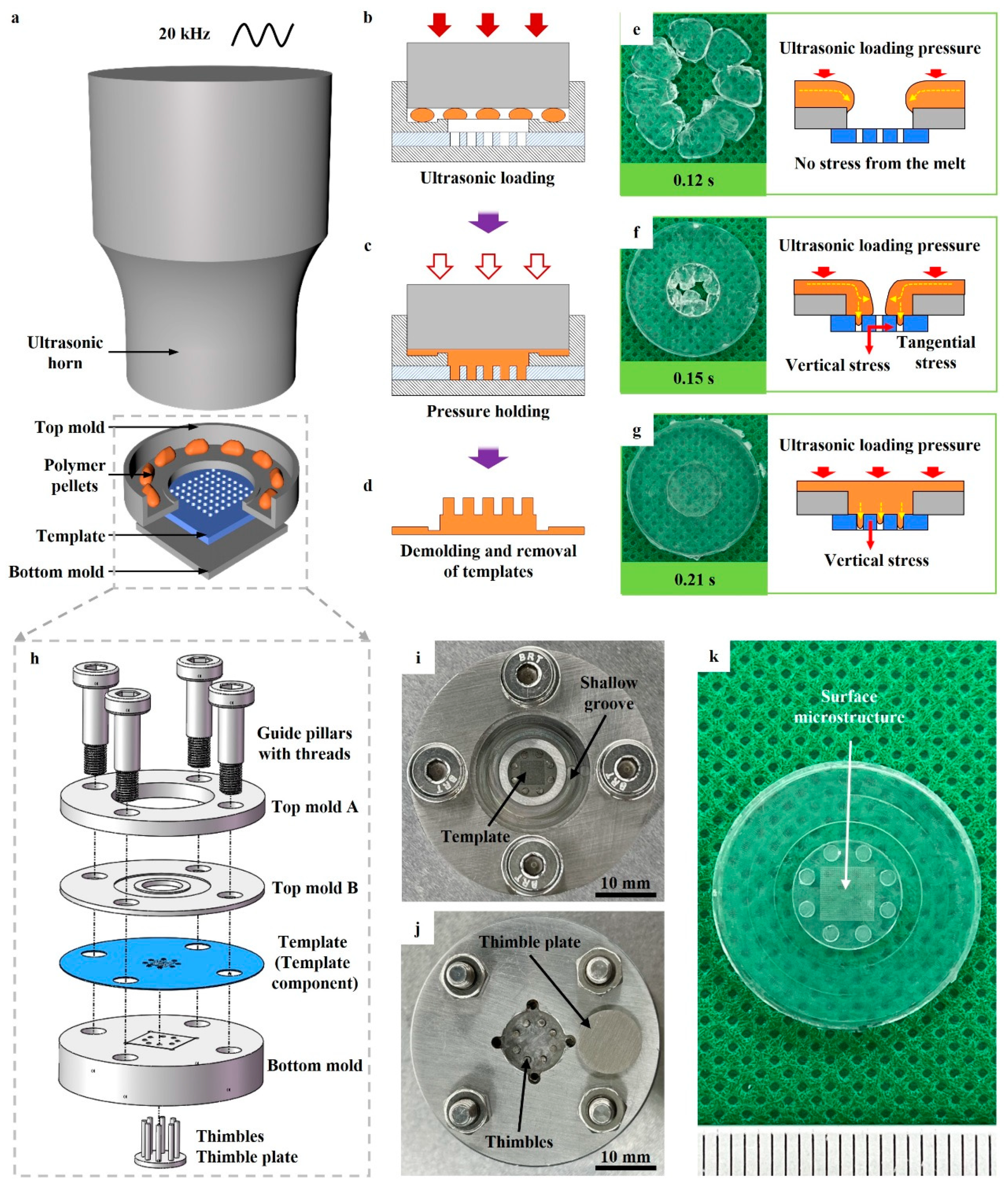
2.1. The UPP Process

The process of UPP consists of the three following stages:
(1) Mold assembly and raw material addition. As shown in Figure 1a, the bottom mold, template, and top mold are mounted and fixed sequentially on the worktable of the ultrasonic loading system, and the punching port of the top mold is aligned with the ultrasonic horn. Then, the thermoplastic polymer pellets are added to the inner step surface of the top mold.
(2) Setting process parameters and ultrasonic loading. The process parameters, such as resonant frequency, ultrasonic amplitude, ultrasonic trigger pressure and loading pressure, ultrasonic duration time, and pressure holding time, are set. By pressing the start button, the ultrasonic horn rapidly moves downward and presses against the polymer pellets (Figure 1b), and ultrasonic loading is automatically initiated when the pressure reaches the trigger pressure. Under high-frequency vibration, the thermoplastic polymer pellets are rapidly plasticized and melted due to frictional and viscoelastic heat [29,30,31], and then fill the micropores of the template. After ultrasonic loading, the melt in the micropores is rapidly cooled and solidified during pressure holding (Figure 1c).
(3) Demolding and removal of templates. After pressure holding, demolding, and removal of templates to obtain the surface microstructures (Figure 1d).

2.2. Materials, Templates, and Equipment

The raw material was polypropylene pellets with a size of about 3 × 2.5 × 5 mm3, which were supplied by Korea Chungnam Lotte Chemical Co., Seoul, Republic of Korea. The primary template with a micropore (through-hole) array was obtained by laser cutting a 304 stainless steel thin sheet with a thickness of 0.2 mm. Two primary templates were designed, one with a pore diameter of 100 μm and a pitch of 150 μm, and the other with a pore diameter of 50 μm and a pitch of 100 μm. In order to facilitate the description and differentiation, the above two templates are named D100-array-LC and D50-array-LC after laser cutting, respectively, and the latter is renamed D50-array-LCM after re-cutting by adjusting the process parameter. The secondary templates were made of anodic aluminum oxide (AAO) with ordered pore arrays, including two specifications, one with a pore size of 390 nm and a pitch of 450 nm, and the other with a pore size of 250 nm and a pitch of 450 nm, and the thickness of both specifications was 50 μm. These two AAO templates are named 390 nm-AAO and 250 nm-AAO, respectively.
The equipment used in this paper is an ultrasonic loading system, which mainly consists of a pneumatic piston, a transducer, a horn, a worktable, an air source, and a power supply. The pneumatic piston converts the air pressure into the mechanical pressure of the horn. The piezoelectric ceramic of the transducer converts the alternating current into high-frequency mechanical vibration, which can realize the ultrasonic loading on the sample through the horn. The resonant frequency and maximum amplitude of ultrasonic vibration are 20 kHz and 60 μm, respectively.
Figure 1h shows the mold designed for UPP, which mainly consists of the bottom mold, thimbles and thimble plate, template (template component), top mold B, top mold A, and the guide pillars with threads. A shallow groove was designed on the top of mold B to hold polymer pellets and to prevent the polymer pellets from being vibrated down onto the template microstructure at the moment of initiating ultrasonic vibration. The thimbles and thimble plate were mounted in the deep groove on the lower surface of the bottom mold for quick ejection of the sample. After machining and assembly, the top and bottom of the mold are shown in Figure 1i and Figure 1j, respectively. Figure 1k shows the sample after demolding, and its central region is the formed surface microstructure.

2.3. Fabrication of Micropiller Arrays

The D100-array-LC, D50-array-LC, and D50-array-LCM templates were used in UPP, respectively, for fabricating the micronscale single-stage micropillar arrays. The number of polypropylene pellets was fixed at 8, and the total weight was about 0.18 g. Setting process parameters on the ultrasonic loading system: the ultrasonic trigger pressure, loading pressure, amplitude, and pressure holding time were set to 500 N, 300 kPa, 60 μm, and 5 s, respectively. The ultrasonic duration time for the D100-array-LC template was 0.28 s, while for both the D50-array-LC and D50-array-LCM templates, it was 0.3 s. The micro/nanoscale hierarchical micropillar arrays were prepared by combining D100-array-LC (primary template) with 390 nm-AAO (secondary template), D100-array-LC with 250 nm-AAO, and D50-array-LCM with 250 nm-AAO in UPP. The same process parameters were employed as for preparing the corresponding single-stage micropillar array (using the same primary template). The residual AAO templates embedded in the sample surface were dissolved in the 15% wt NaOH solution within 10 min. The above process parameters were set based on our extensive preliminary experimental results.

2.4. Characterization

The surface microstructures prepared by UPP were examined under scanning electron microscopy (SEM, Quanta FEG450, FEI, Hillsboro, OR, USA) after spray gold treatment. The hydrophobicity of the surface microstructures was characterized by water contact angle (WCA), which was measured by a droplet shape analyzer (DSA100S, Krüss, Hamburg, Germany) with a water droplet volume of 2.5 μL. The lipophilicity was characterized by measuring the time for an oil droplet (micro-molecule lube oil supplied by Cylion Technology Int’L Co. Ltd., Shenzhen, China) with a volume of 1 μL to completely immerse into the surface microstructures; thus, the entire process of oil droplet immersion into the surface microstructures was recorded.

3. Results and Discussion

3.1. The Characteristics and Advantages of UPP

The left sides of Figure 1e–g show the results of polypropylene pellets being plasticized and filling the mold cavities when the ultrasonic duration times were 0.12 s, 0.15, and 0.21 s, respectively. Based on the results, the flow of the melt during ultrasonic loading can be categorized into three stages, as shown on the right sides of Figure 1e, Figure 1f and Figure 1g, respectively. In the first stage, the polymer pellets are plasticized. Under high-frequency vibration, the surface of polymer pellets rubs violently against the horn and mold, generating frictional heat, while viscoelastic heat is generated within the material due to high-frequency alternating stress loads. The frictional and viscoelastic heat leads to a rapid increase in the temperature of polymer pellets with low thermal conductivity, which are plasticized and melted. In the second stage, the melt flows from the top mold to the upper surface of the template and converges to the template center while gradually diverging to the micro-cavity holes. At this stage, the template microstructure is not only subjected to the vertical stress from the melt but also to the tangential stress generated by the converging flow of the melt. Since the ultrasonic loading pressure is mainly applied to the melt on the upper surface of the top mold and is transferred axially to the worktable, whether vertical stress or tangential stress is much smaller than the ultrasonic loading pressure. In the third stage, after the melt has completely covered the upper surface of the template, it continues to fill the template micro-cavity holes. The template microstructure is mainly subjected to vertical stress from the melt, which is comparable in magnitude to ultrasonic loading pressure.
From the melt flow diagrams, it can be seen that during ultrasonic loading, the melt and the micro-cavity holes are always directly under the horn, and are subject to the continuous action of ultrasonic longitudinal vibration (main vibration). This can fully utilize the role of ultrasonic vibration. On the one hand, it effectively reduces the melt viscosity [32,33], thus improving the filling ability of the melt to the micro-cavity holes [34,35,36]. On the other hand, it is conducive to the elimination of residual air inside the micro-cavity holes [19,37], which reduces the formation of air bubbles and thus improves the forming quality of surface microstructures. From the stress diagrams, it can be seen that for the templates used in this work, only the tangential stress may cause deformation or fracture of the template microstructure, but this stress is much smaller than the ultrasonic loading pressure. In addition, UPP avoids violent friction between the polymer pellets or substrate and the template microstructure. Therefore, combined with the results of Figure S1, it can be demonstrated that UPP is not prone to deformation or even fracture of the template microstructure while ensuring sufficiently large melt filling pressure, which is favorable for the reuse of the template.

3.2. Micronscale Single-Stage Arrays

Figure 2a shows the D100-array-LC template, where the upper surface (laser-cut surface) of the template is outside the red box and the lower surface is inside the red box. The diameters of the circular holes on the upper and lower surfaces are about 115.9 μm and 106.0 μm, respectively, thus the template has a demolding angle of 1.42°. The top and side views of the single-stage column array prepared by using the D100-array-LC template are shown in Figure 2d and Figure 2g, respectively. In Figure 2g, the solid box is a close-up view of the dashed box. It can be found that the diameter, height, and pitch of the prepared column array are consistent with the corresponding structural parameters of the template, respectively. The column array is structurally intact and aesthetically pleasing. The results indicate that the polypropylene melt filled the micropores adequately under the continuous action of ultrasound vibration. In Figure 2j, the micropore array of the D100-array-LC template remains intact and unobstructed after multiple uses, indicating that the template can be recycled.
As shown in Figure 2b, the diameters of the circular holes on the upper and lower surfaces of the D50-array-LC template are about 67.9 μm and 51.3 μm, respectively. The demolding angle of the D50-array-LC template is 2.38°. Figure 2e,h show the top and side views of the column array obtained by using this template, respectively. It can be observed that the polypropylene melt was able to completely fill the micropores, and the array structure was complete after solidification. However, some of the columns were stretched and deformed due to excessive demolding resistance during ejection. Figure 2k demonstrates that after multiple uses, the micropores of the D50-array-LC template were gradually blocked by the polypropylene pillars that were pulled off due to excessive demolding resistance. Therefore, it is necessary to reduce the roughness of the inner surface of the micropores or increase the demolding angle of the micropores by adjusting the laser cutting parameters of the template. In Figure 2c, the diameters of the circular holes on the upper and lower surfaces of the D50-array-LCM template are approximately 64.6 μm and 33.1 μm, respectively. Consequently, the demolding angle is increased to 4.5°. As shown in Figure 2f,i, the cone-column array prepared by using the D50-array-LCM template is neat and aesthetic, with no cone columns being stretched or deformed. The overall forming quality is very good, although there is a tiny flash on top of the cone column. Figure 2l shows the micropore array of the D50-array-LCM template after multiple uses; it remains intact and unobstructed. The results indicate that the template with a proper demolding angle can be recycled in UPP and achieve damage-free demolding of the micropillar array.
In this section, a single-stage column array with a diameter of about 110 μm, a height of 200 μm, and a pitch of 150 μm, as well as a single-stage cone-column array with a top diameter of about 33 μm, a root diameter of about 64 μm, a height of 200 μm, and a pitch of 100 μm, were successfully fabricated by UPP.

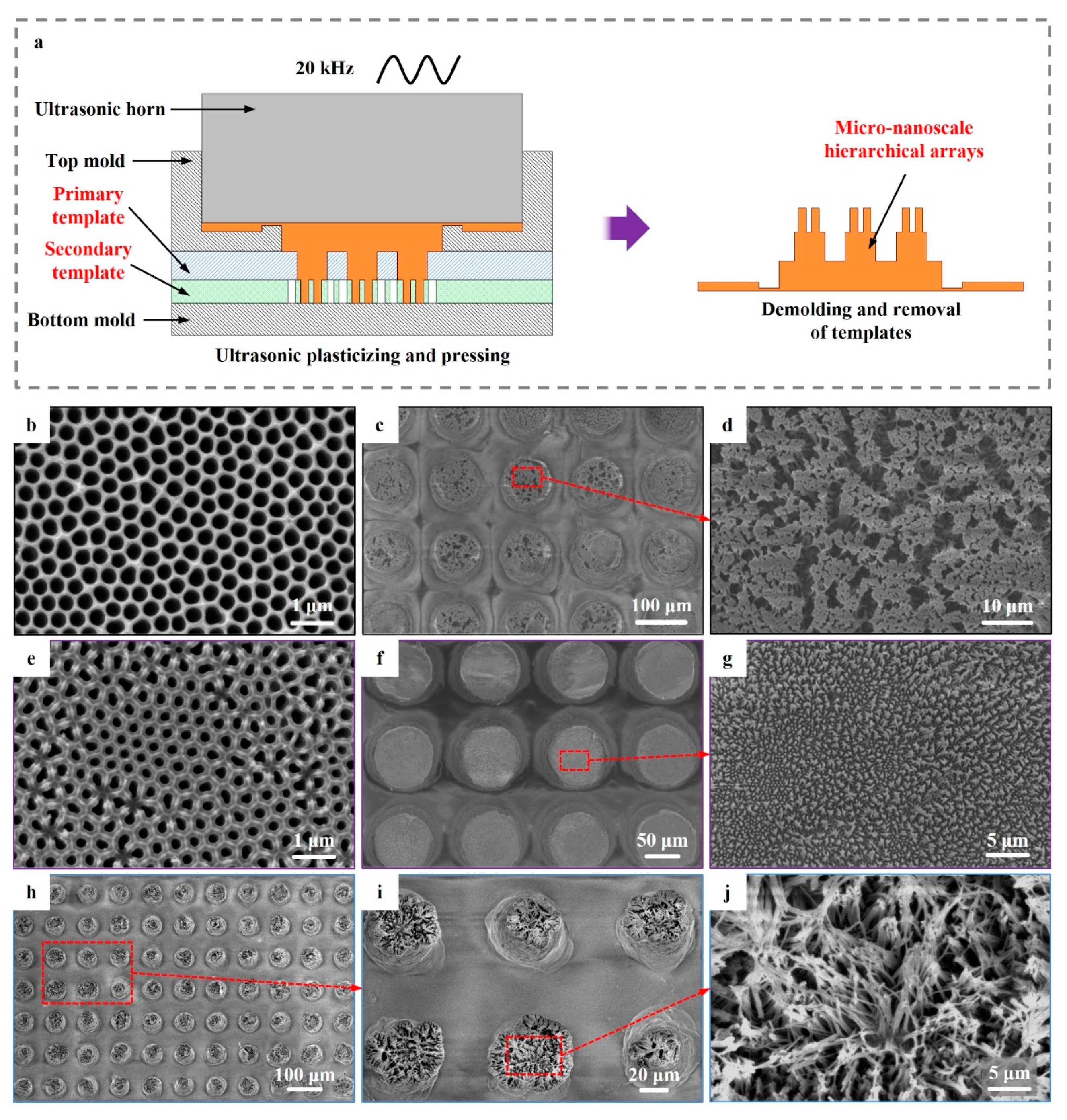
3.3. Micro/Nanoscale Hierarchical Arrays

The successful fabrication of a micronscale micropillar array with a high aspect ratio (~4.1) indicates that the polymer melt has a very strong ability to fill micropores during UPP. Therefore, multilevel templates can be set up for the fabrication of hierarchical array structures. In Figure 3a, a secondary template with nanoscale pores is added below the primary template with micron-scale pores. When ultrasonic loading is initiated, the polymer pellets are plasticized and melted, rapidly filling the micropores of the two-stage templates under ultrasonic vibration. After pressure holding, the sample is demolded, and the residual templates are removed to obtain the micro/nanoscale hierarchical arrays.
Figure 3c,d show the hierarchical micropillar arrays prepared by combining the D100-array-LC template (primary template) with the 390 nm-AAO template (secondary template, Figure 3b). It can be found that the top of the column with an intact array structure is covered with a nanowire array. The results indicate that under the continuous action of the horn and ultrasonic vibration, the polypropylene melt can continue to fill the ordered nanopore array of the secondary template after completely filling the micropores of the primary template, which adequately demonstrates that UPP has superb micro- and nano-pore filling ability. Obviously, the formed nanowires are severely agglomerated. The residual bending stresses of the polypropylene nanowires after solidification at room temperature were released upon dissolution of the AAO template [24], and the pore margin of the 390 nm-AAO template was much smaller relative to the pore diameter, thus leading to the bending of the high aspect ratio nanowires and the formation of severe agglomerates in various localized regions. Figure 3f,g show the hierarchical micropillar arrays prepared by combining the D100-array-LC template with the 250 nm-AAO template (Figure 3e). Although nanowire agglomeration still exists, it is slight as the pore margin of the 250 nm-AAO template is comparable to the pore diameter.
Figure 3h–j show the hierarchical micropillar arrays prepared by combining the D50-array-LCM template with the 250 nm-AAO template. The nanowire array (diameter 250 nm, height about 5 μm, and aspect ratio up to 20) covers the top of the cone-column. In the center region, the nanowires are well defined with slight agglomeration, while in the edge region, dumping and severe agglomeration of nanowires are present. Since the micropores of the D50-array-LCM template were small and dense, and the microporous cutting depth of 200 μm was large relative to the pore diameter, tiny localized warping deformations inevitably occurred in the micropore array after laser cutting. This warping deformation resulted in gaps between the lower surface of the micropore array and the upper surface of the bottom mold or secondary template. During single-stage cone-column array preparation, the polypropylene melt filled the gaps under ultrasonic vibration; thus, tiny flashes were formed at the edge of the cone-column top, which can be clearly observed in Figure 2i. While hierarchical micropillar arrays were being prepared, the polypropylene melt not only filled the gaps but also filled the ordered nanopore array underneath the gaps. The solidified flashes were pulled and compressed to shape under the constraints of the micropores of the primary template during demolding. As a result, the nanowires formed on the flash surface deformed along with the flash, leading to dumping and severe agglomeration of the nanowires in the edge region. The formation of nanowires on the flash surface caused by machining defects of the template exactly demonstrates the superb micro- and nano-pore filling ability of the polymer melt in UPP.
In this section, φ110 μm and φ390 nm, φ110 μm and φ250 nm, and φ64-33 μm and φ250 nm hierarchical micropillar arrays were successfully fabricated, which verifies the capability of UPP to fabricate micro/nanoscale hierarchical surface microstructures with high aspect ratios.

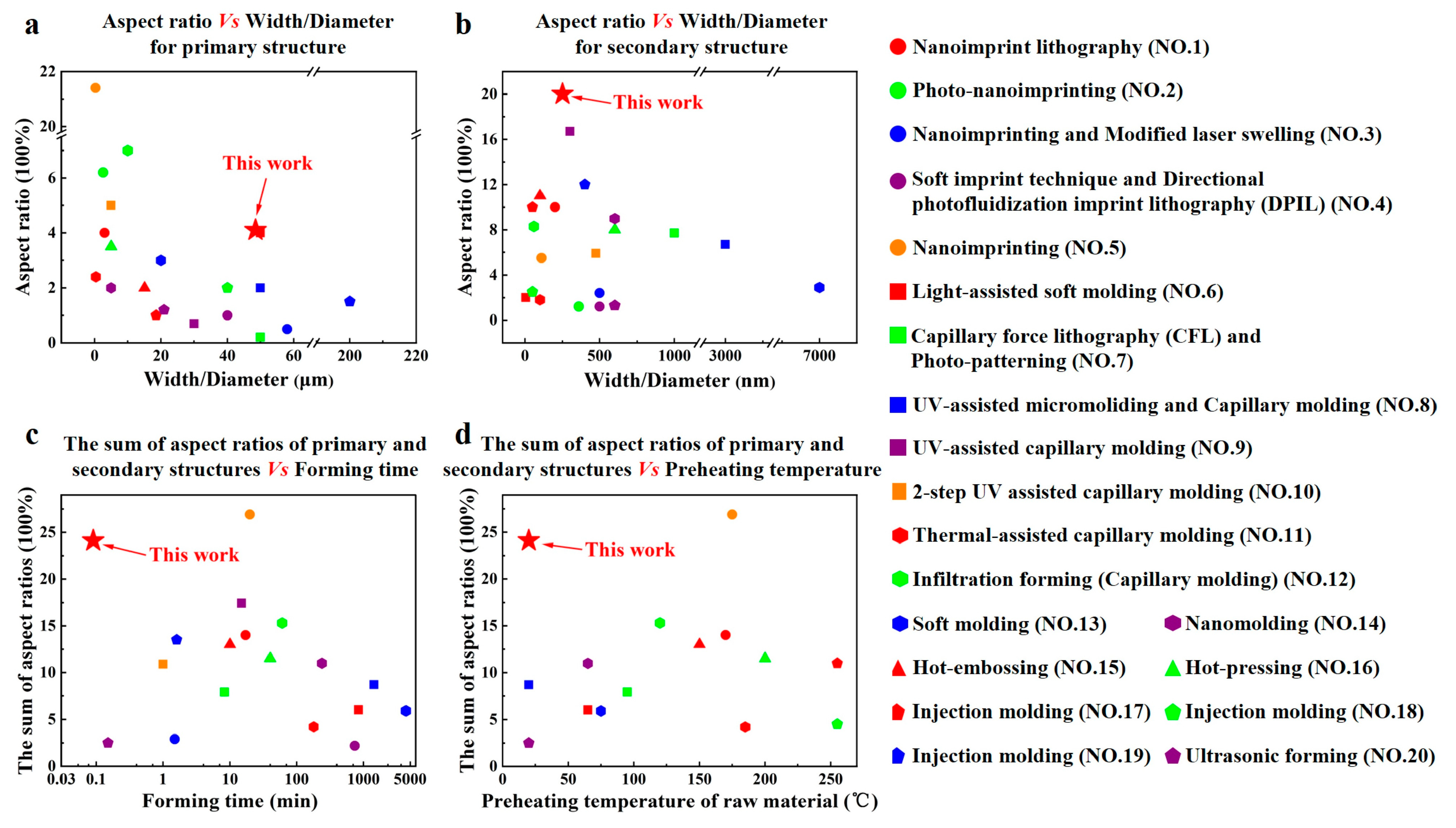
3.4. Comparison with Other Methods for Fabricating Micropillar Arrays
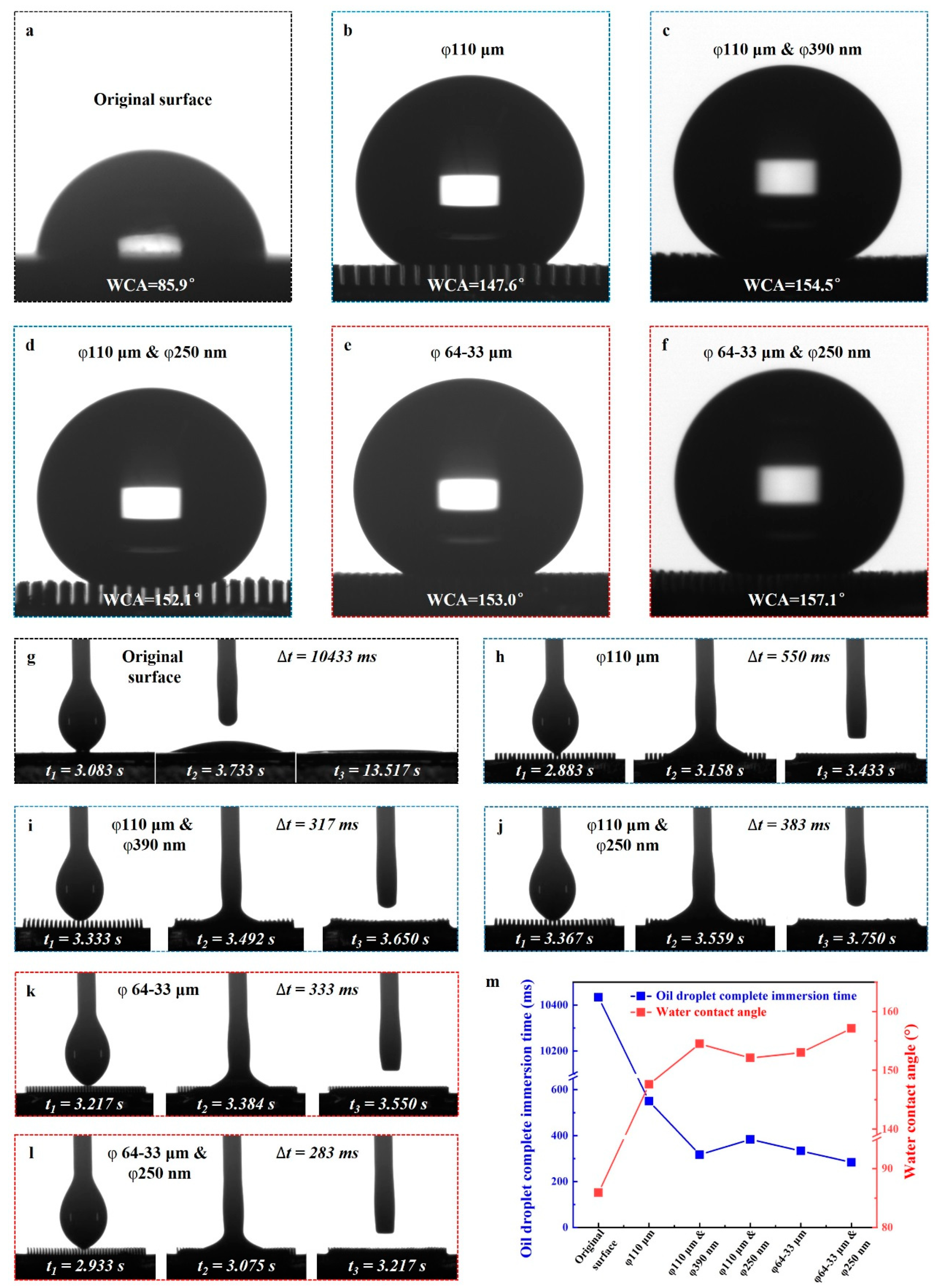
To demonstrate the superiority of UPP, the previous work on the fabrication of hierarchical micropillar arrays by the template method and the results thereof have been summarized in Table S1. Microstructure scale, aspect ratio, forming time, and preheating temperature of raw material are the key indexes for evaluating the merits and drawbacks of a forming method. The microstructure scale and aspect ratio reflect the forming capability of the method, while the forming time and preheating temperature of the raw material directly affect the production cost. Therefore, the above indexes are extracted from Table S1 for comparison, as shown in Figure 4. Among the previous results in Table S1, the aspect ratio of primary structure (micron-scale) of the hierarchical micropillar arrays prepared in this work is within the top 25% (Figure 4a), while the aspect ratio of secondary structure (nanoscale) is the highest, up to 20 (Figure 4b). The sum of the aspect ratios of primary and secondary structures in this work is 24.1, which is only 2.8 smaller than that of the highest (nanoimprinting, No.5). However, UPP has the shortest forming time (only 5.3 s; Figure 4c) and does not need to heat the raw material (at room temperature; Figure 4d), whereas nanoimprinting (No.5) requires a forming time of 20 min and heating the raw material up to 175 °C. In other aspects, some methods (No.1, No.3, No.4, No.7, No.8, and No.10) need two-step preparation of the primary and secondary structures, some methods (No.3, No.4, and No.6–10) are limited to the light-cured materials, and some methods (No.4, No.5, No.8, No.11, No.14, No.15, and No.17–19) require a vacuum environment or preheating of the mold, while UPP can form multilayer structures in one step at room temperature without preheating the mold. Therefore, UPP has obvious superiority in mass production of polymer surface microstructures due to its superb forming capability of microstructures and nanostructures, simple process, short production cycle, and low cost.
Ultrasonic molding technology, which utilizes ultrasonic vibration as the main energy source to plasticize thermoplastic polymers, has become a promising microstructure replication technology with the advantages of short forming timed, simple equipment, and low cost. Table 1 summarizes the results of the previous work on the preparation of single-stage or hierarchical micropillar arrays by ultrasonic molding technology. Among the previous results, the aspect ratios of the micropillar arrays prepared in this work are the highest and far ahead, regardless of the micronscale or nanoscale. In addition, UPP has the shortest ultrasonic duration. As shown in Table 1, only two previous works have successfully fabricated nanoscale micropillar arrays, and even less, only one previous work has successfully fabricated micro/nanoscale hierarchical micropillar arrays, but the aspect ratios of the primary and secondary structures are only 1.2 and 1.3, respectively. Therefore, ultrasonic molding technology is almost blank in the preparation of single-stage or hierarchical micropillar arrays with high aspect ratios, whereas UPP achieves a significant breakthrough in this aspect, fast-tracking the development and application of ultrasonic molding technology.

3.5. Wettability

As shown in Figure 5a–f, the WCA of the polypropylene original surface is 85.9°, while the WCAs of the φ110 μm column array and φ64-33 μm cone-column array are 147.6° and 153.0°, which are 71.83% and 78.11% higher than the WCA of the original surface, respectively. Compared with the corresponding single-stage micropillar arrays, the WCAs of φ110 μm and φ390 nm, φ110 μm and φ250 nm, and φ64-33 μm and φ250 nm hierarchical micropillar arrays are further improved due to the presence of nanowire arrays, which are 154.5°, 152.1°, and 157.1°, respectively. According to the Cassie–Baxter model [44], when air in the gaps between the microstructures prevents the droplets from filling the surface microstructure, the WCA is expressed by the following formula:
cos θ C B = f 1 + cos θ Y 1
where θCB is the WCA, θY is the intrinsic WCA on a structure-free surface, and f is the fraction of the solid surface in contact with the liquid. The dense micropillars and nanowires effectively increased the water–air contact area between the droplets and the solid surface and changed the contact state, resulting in a significant decrease in the f value. Therefore, the WCAs of the micropillar arrays were improved to different degrees.
Figure 5g–l show three states and the corresponding moments during the immersion of oil droplets into the original surface and five micropillar arrays prepared in this work, respectively, including the states of beginning contact, a certain moment during the period, and complete immersion. It can be noticed that it was difficult for the oil droplet to completely immerse into the polypropylene original surface, and the time required for the state at the moment t3 was 10,433 ms (Figure 5g). However, for the prepared micropillar arrays, it was easy to achieve complete immersion of the oil droplet, and the time required for φ110 μm and φ250 hierarchical micropillar arrays was the shortest, only 283 ms (Figure 5l). As shown in Figure 5m, the trends of the WCA and the oil droplet complete immersion time are exactly opposite. The results indicate that the presence of prepared micropillar arrays ensures complete immersion of the oil, and the larger the contact angle, the faster the immersion rate. In conclusion, the surface microstructures prepared in this work have superhydrophobic and superoleophilic properties.

4. Conclusions

(1) UPP makes full use of ultrasonic vibration, avoids violent friction between the raw material and the template microstructure, and is therefore particularly suitable for reproducing surface microstructures with high aspect ratios from templates.
(2) Micron-scale single-stage micropillar arrays with an aspect ratio of 4.1 and micro-nanoscale hierarchical micropillar arrays with an aspect ratio of 24.1 were successfully prepared, verifying the feasibility and forming capability of UPP.
(3) Compared with other template methods for fabricating polymer surface microstructures, UPP possesses the advantages of superb forming capability of micro- and nano-structures, simple process, short production cycle and high cost-effectiveness. Therefore, it has potential uses in both research and application.
(4) UPP has achieved a significant breakthrough in ultrasonic molding technology in the fabrication of micropillar arrays with high aspect ratios.
(5) The prepared PP micropillar arrays have superhydrophobic and superoleophilic properties.

Supplementary Materials

The following supporting information can be downloaded at: https://www.mdpi.com/article/10.3390/pr12050856/s1, References [45,46,47,48,49,50,51,52,53,54,55,56,57,58,59,60,61,62,63,64] are cited in Supplementary Materials.

Author Contributions

Methodology, S.W.; Validation, S.W.; Formal analysis, S.X.; Investigation, S.W. and S.X.; Resources, J.D.; Writing—original draft, S.W.; Writing—review & editing, S.W., J.D. and J.M.; Visualization, J.L. and L.Z.; Supervision, J.D.; Funding acquisition, J.D., J.L., J.M. and L.Z. All authors have read and agreed to the published version of the manuscript.

Funding

The current work was supported, in part, by the Guangdong HUST Industrial Technology Research Institute, the Guangdong Provincial Key Laboratory of Manufacturing Equipment Digitization (2023B1212060012), and Shenzhen Stable Support B Plan (Grant No. 20231120184926001).

Data Availability Statement

Data are contained within the article and Supplementary Materials.

Conflicts of Interest

The authors declare that they have no known competing financial interests or personal relationships that could have appeared to influence the work reported in this paper.

References

  1. Peng, Y.J.; Huang, H.X.; Xie, H. Rapid fabrication of antireflective pyramid structure on polystyrene film used as protective layer of solar cell. Sol. Energy Mater. Sol. Cells 2017, 171, 98–105. [Google Scholar] [CrossRef]
  2. Fu, J.; Li, Z.; Li, X.; Sun, F.; Li, L.; Li, H.; Zhao, J.; Ma, J. Hierarchical porous metallic glass with strong broadband absorption and photothermal conversion performance for solar steam generation. Nano Energy 2023, 106, 108019. [Google Scholar] [CrossRef]
  3. Tadepalli, S.; Slocik, J.M.; Gupta, M.K.; Naik, R.R.; Singamaneni, S. Bio-optics and bio-inspired optical materials. Chem. Rev. 2017, 117, 12705–12763. [Google Scholar] [CrossRef] [PubMed]
  4. Bandara, C.D.; Singh, S.; Afara, I.O.; Wolff, A.; Tesfamichael, T.; Ostrikov, K.; Oloyede, A. Bactericidal effects of natural nanotopography of dragonfly wing on escherichia coli. ACS Appl. Mater. Interfaces 2017, 9, 6746–6760. [Google Scholar] [CrossRef] [PubMed]
  5. Tsui, K.H.; Li, X.; Tsoi, J.K.H.; Leung, S.F.; Tang, L.; Chak, W.Y.; Zhang, C.; Chen, J.; Cheung, G.S.P.; Fan, Z. Low-cost, flexible, disinfectant-free and regular-array three-dimensional nanopyramid antibacterial films for clinical applications. Nanoscale 2018, 10, 10436–10442. [Google Scholar] [CrossRef] [PubMed]
  6. Hu, D.; Deng, Y.; Jia, F.; Jin, Q.; Ji, J. Surface charge switchable supramolecular nanocarriers for nitric oxide synergistic photodynamic eradication of biofilms. ACS Nano 2020, 14, 347–359. [Google Scholar] [CrossRef] [PubMed]
  7. Ye, S.; Cheng, C.; Chen, X.; Chen, X.; Shao, J.; Zhang, J.; Hu, H.; Tian, H.; Li, X.; Ma, L.; et al. High-performance piezoelectric nanogenerator based on microstructured P (VDF-TrFE)/BNNTs composite for energy harvesting and radiation protection in space. Nano Energy 2019, 60, 701–714. [Google Scholar] [CrossRef]
  8. Zhang, Y.; Han, F.; Hu, Y.; Xiong, Y.; Gu, H.; Zhang, G.; Zhu, P.; Sun, R.; Wong, C.P. Flexible and highly sensitive pressure sensors with surface discrete microdomes made from self-assembled polymer microspheres array. Macromol. Chem. Phys. 2020, 221, 2000073. [Google Scholar] [CrossRef]
  9. Attia, U.M.; Marson, S.; Alcock, J.R. Micro-injection moulding of polymer microfluidic devices. Microfluid. Nanofluid. 2009, 7, 1–28. [Google Scholar] [CrossRef]
  10. Rytka, C.; Kristiansen, P.M.; Neyer, A. Iso- and variothermal injection compression moulding of polymer micro-and nanostructures for optical and medical applications. J. Micromech. Microeng. 2015, 25, 065008. [Google Scholar] [CrossRef]
  11. Hench, L.L.; West, J.K. The sol-gel process. Chem. Rev. 1990, 90, 33–72. [Google Scholar] [CrossRef]
  12. Dudem, B.; Heo, J.H.; Leem, J.W.; Yu, J.S.; Im, S.H. CH3NH3PbI3 planar perovskite solar cells with antireflection and self-cleaning function layers. J. Mater. Chem. A 2016, 4, 7573–7579. [Google Scholar] [CrossRef]
  13. Zhang, Y.; Lin, C.T.; Yang, S. Fabrication of hierarchical pillar arrays from thermoplastic and photosensitive SU-8. Small 2010, 6, 768–775. [Google Scholar] [CrossRef] [PubMed]
  14. Jeong, H.E.; Suh, K.Y. On the role of oxygen in fabricating microfluidic channels with ultraviolet curable materials. Lab Chip 2008, 8, 1787–1792. [Google Scholar] [CrossRef]
  15. Deshmukh, S.S.; Goswami, A. Hot embossing of polymers—A review. Mater. Today Proc. 2020, 26, 405–414. [Google Scholar] [CrossRef]
  16. Li, J.M.; Liu, C.; Peng, J. Effect of hot embossing process parameters on polymer flow and microchannel accuracy produced without vacuum. J. Mater. Process. Technol. 2008, 207, 163–171. [Google Scholar] [CrossRef]
  17. Giboz, J.; Copponnex, T.; Mélé, P. Microinjection molding of thermoplastic polymers: A review. J. Micromech. Microeng. 2007, 17, R96. [Google Scholar] [CrossRef]
  18. Sha, B.; Dimov, S.; Griffiths, C.; Packianather, M.S. Investigation of micro-injection moulding: Factors affecting the replication quality. J. Mater. Process. Technol. 2007, 183, 284–296. [Google Scholar] [CrossRef]
  19. Mekaru, H.; Nakamura, O.; Maruyama, O.; Maeda, R.; Hattori, T. Development of precision transfer technology of atmospheric hot embossing by ultrasonic vibration. Microsyst. Technol. 2007, 13, 385–391. [Google Scholar] [CrossRef]
  20. Sato, A.; Ito, H.; Koyama, K. Study of application of ultrasonic wave to injection molding. Polym. Eng. Sci. 2009, 49, 768–773. [Google Scholar] [CrossRef]
  21. Qiu, Z.; Yang, X.; Zheng, H.; Gao, S.; Fang, F. Investigation of micro-injection molding based on longitudinal ultrasonic vibration core. Appl. Opt. 2015, 54, 8399–8405. [Google Scholar] [CrossRef] [PubMed]
  22. Yu, H.W.; Lee, C.H.; Jung, P.G.; Shin, B.S.; Kin, J.H.; Hwang, K.Y.; Ko, J.S. Polymer microreplication using ultrasonic vibration energy. J. Micro/Nanolithogr. MEMS MOEMS 2009, 8, 021113. [Google Scholar] [CrossRef]
  23. Lee, C.H.; Jung, P.G.; Lee, S.M.; Park, S.H.; Shin, B.S.; Kim, J.H.; Hwang, K.Y.; Ko, J.S. Replication of polyethylene nano-micro hierarchical structures using ultrasonic forming. J. Micromech. Microeng. 2010, 20, 035018. [Google Scholar] [CrossRef]
  24. Li, Z.; Fu, J.; Zhang, L.; Ma, J.; Shen, J. Rapid Forming of Nanowire Array on Polyvinylidene Fluoride Polymer Surfaces at Room Temperature by Ultrasonic Loading. J. Adv. Eng. Mater. 2023, 25, 2200700. [Google Scholar] [CrossRef]
  25. Liang, X.; Liu, Y.; Chen, S.; Ma, J.; Wu, X.; Shi, H.; Fu, L.; Xu, B. Fabrication of microplastic parts with a hydrophobic surface by micro ultrasonic powder moulding. J. Manuf. Process. 2020, 56, 180–188. [Google Scholar] [CrossRef]
  26. Pan, L.; Wu, W.; Jia, C.; Liu, J. Ultrasonic plasticization micro-injection molding technology: Characterization of replication fidelity and wettability of high-depth microstructure. J. Polym. Res. 2023, 30, 349. [Google Scholar] [CrossRef]
  27. Liang, X.; Wu, X.; Xu, B.; Ma, J.; Liu, Z.; Peng, T.; Fu, L. Phase structure development as preheating UHMWPE powder temperature changes in the micro-UPM process. J. Micromech. Microeng. 2016, 26, 015014. [Google Scholar] [CrossRef]
  28. Jiang, B.; Zou, Y.; Liu, T.; Wu, W. Characterization of the fluidity of the ultrasonic plasticized polymer melt by spiral flow testing under micro-scale. Polymers 2019, 11, 357. [Google Scholar] [CrossRef]
  29. Jiang, B.; Peng, H.; Wu, W.; Jia, Y.; Zhang, Y. Numerical simulation and experimental investigation of the viscoelastic heating mechanism in ultrasonic plasticizing of amorphous polymers for micro injection molding. Polymers 2016, 8, 199. [Google Scholar] [CrossRef]
  30. Janer, M.; Planta, X.; Riera, D. Ultrasonic moulding: Current state of the technology. Ultrasonics 2020, 102, 106038. [Google Scholar] [CrossRef]
  31. Wu, W.; Peng, H.; Jia, Y.; Jiang, B. Characteristics and mechanisms of polymer interfacial friction heating in ultrasonic plasticization for micro injection molding. Microsyst. Technol. 2017, 23, 1385–1392. [Google Scholar] [CrossRef]
  32. Chen, J.; Chen, Y.; Li, H.; Lai, S.Y.; Jow, J. Physical and chemical effects of ultrasound vibration on polymer melt in extrusion. Ultrason. Sonochem. 2010, 17, 66–71. [Google Scholar] [CrossRef]
  33. Peshkovskii, S.L.; Friedman, M.L.; Tukachinskii, A.I.; Vinogradov, G.V.; Enikolopian, N.S. Acoustic cavitation and its effect on flow in polymers and filled systems. Polym. Compos. 1983, 4, 126–134. [Google Scholar] [CrossRef]
  34. Yang, Y.J.; Huang, C.C.; Lin, S.K.; Tao, J. Characteristics analysis and mold design for ultrasonic assisted injection molding. J. Polym. Eng. 2014, 34, 673–681. [Google Scholar] [CrossRef]
  35. Yang, Y.J.; Huang, C.C.; Tao, J. Application of ultrasonic-assisted injection molding for improving melt flowing and floating fibers. J. Polym. Eng. 2016, 36, 119–128. [Google Scholar] [CrossRef]
  36. Yang, Y.J.; Huang, C.C. Effects of ultrasonic injection molding conditions on the plate processing characteristics of PMMA. J. Polym. Eng. 2018, 38, 905–914. [Google Scholar] [CrossRef]
  37. Liu, S.J.; Dung, Y.T. Hot embossing precise structure onto plastic plates by ultrasonic vibration. Polym. Eng. Sci. 2005, 45, 915–925. [Google Scholar] [CrossRef]
  38. Chang, C.Y.; Yu, C.H. A basic experimental study of ultrasonic assisted hot embossing process for rapid fabrication of microlens arrays. J. Micromech. Microeng. 2015, 25, 025010. [Google Scholar] [CrossRef]
  39. Zhu, J.; Tian, Y.; Yang, C.; Cai, L.; Wang, F.; Zhang, D.; Liu, X. Low-cost and fast fabrication of the ultrasonic embossing on polyethylene terephthalate (PET) films using laser processed molds. Microsyst. Technol. 2017, 23, 5653–5668. [Google Scholar] [CrossRef]
  40. Liao, S.; Gerhardy, C.; Sackmann, J.; Schomburg, W.K. Tools for ultrasonic hot embossing. Microsyst. Technol. 2015, 21, 1533–1541. [Google Scholar] [CrossRef]
  41. Liang, X.; Li, B.; Wu, X.; Shi, H.; Zeng, K.; Wang, Y. Micro UHMW-PE column array molded by the utilization of PCB as mold insert. Circuit World 2013, 39, 95–101. [Google Scholar] [CrossRef]
  42. Gülür, M.; Brown, E.; Gough, T.; Romano, J.M.; Penchev, P.; Dimov, S.; Whiteside, B. Ultrasonic micromoulding: Process characterisation using extensive in-line monitoring for micro-scaled products. J. Manuf. Process. 2020, 58, 289–301. [Google Scholar] [CrossRef]
  43. Pan, L.; Wu, W.; Liu, J.; Li, X. Ultrasonic plasticization microinjection precision molding of polypropylene microneedle arrays. ACS Appl. Polym. Mater. 2023, 5, 9354–9363. [Google Scholar] [CrossRef]
  44. Cassie, A.; Baxter, S. Wettability of Porous Surfaces. Trans. Faraday Soc. 1944, 40, 546–551. [Google Scholar] [CrossRef]
  45. Raut, H.K.; Baji, A.; Hariri, H.H.; Parveen, H.; Soh, G.S.; Low, H.Y.; Wood, K.L. Gecko-inspired dry adhesive based on micro-nanoscale hierarchical arrays for application in climbing devices. ACS Appl. Mater. Interfaces 2018, 10, 1288–1296. [Google Scholar] [CrossRef] [PubMed]
  46. Yanagishita, T.; Sou, T.; Masuda, H. Micro-nano hierarchical pillar array structures prepared on curved surfaces by nanoimprinting using flexible molds from anodic porous alumina and their application to superhydrophobic surfaces. RSC Adv. 2022, 12, 20340–20347. [Google Scholar] [CrossRef] [PubMed]
  47. Shao, J.; Ding, Y.; Wang, W.; Mei, X.; Zhai, H.; Tian, H.; Li, X.; Liu, B. Generation of fully-covering hierarchical micro-/nano-structures by nanoimprinting and modified laser swelling. Small 2014, 10, 2595–2601. [Google Scholar] [CrossRef] [PubMed]
  48. Choi, J.; Cho, W.; Jung, Y.S.; Kang, H.S.; Kin, H.T. Direct fabrication of micro/nano-patterned surfaces by vertical-directional photofluidization of azobenzene materials. ACS Nano 2017, 11, 1320–1327. [Google Scholar] [CrossRef] [PubMed]
  49. Ho, A.Y.Y.; Yeo, L.P.; Lam, Y.C.; Rodriguez, I. Fabrication and analysis of gecko-inspired hierarchical polymer nanosetae. ACS Nano 2011, 5, 1897–1906. [Google Scholar] [CrossRef] [PubMed]
  50. Greiner, C.; Arzt, E.; Campo, A.D. Hierarchical gecko-like adhesives. Adv. Mater. 2009, 21, 479–482. [Google Scholar] [CrossRef]
  51. Aksak, B.; Murphy, M.P.; Sitti, M. Adhesion of biologically inspired vertical and angled polymer microfiber arrays. Langmuir 2007, 23, 3322–3332. [Google Scholar] [CrossRef] [PubMed]
  52. Murphy, M.P.; Aksak, B.; Sitti, M. Adhesion and anisotropic friction enhancements of angled heterogeneous micro-fiber arrays with spherical and spatula tips. J. Adhes. Sci. Technol. 2007, 21, 1281–1296. [Google Scholar] [CrossRef]
  53. Murphy, M.P.; Kim, S.; Sitti, M. Enhanced adhesion by gecko-inspired hierarchical fibrillar adhesives. ACS Appl. Mater. Interfaces 2009, 1, 849–855. [Google Scholar] [CrossRef] [PubMed]
  54. Ma, Z.; Jiang, C.; Li, X.; Ye, F.; Yuan, W. Controllable fabrication of periodic arrays of high-aspect-ratio micro-nano hierarchical structures and their superhydrophobicity. J. Micromech. Microeng. 2013, 23, 095027. [Google Scholar] [CrossRef]
  55. Jeong, H.E.; Lee, J.K.; Kim, H.N.; Moon, S.H.; Suh, K.Y. A nontransferring dry adhesive with hierarchical polymer nanohairs. Proc. Natl. Acad. Sci. USA 2009, 106, 5639–5644. [Google Scholar] [CrossRef] [PubMed]
  56. Lee, D.Y.; Lee, D.H.; Lee, S.G.; Cho, K. Hierarchical gecko-inspired nanohairs with a high aspect ratio induced by nanoyielding. Soft Matter 2012, 8, 4905–4910. [Google Scholar] [CrossRef]
  57. Kustandi, T.S.; Samper, V.D.; Ng, W.S.; Chong, A.S.; Gao, H. Fabrication of a gecko-like hierarchical fibril array using a bonded porous alumina template. J. Micromech. Microeng. 2007, 17, N75. [Google Scholar] [CrossRef]
  58. Jin, K.J.; Tian, Y.; Erickson, J.S.; Puthoff, J.; Autumn, K.; Pesika, N.S. Design and Fabrication of Gecko-Inspired Adhesives. Langmuir 2012, 28, 5737–5742. [Google Scholar] [CrossRef] [PubMed]
  59. Sitti, M. High aspect ratio polymer micro/nano-structure manufacturing using nanoembossing, nanomolding and directed self-assembly. In Proceedings of the 2003 IEEE/ASME International Conference on Advanced Intelligent Mechatronics, Kobe, Japan, 20–24 July 2003. [Google Scholar]
  60. Li, K.; Hernandez-Castro, J.A.; Turcotte, K.; Morton, K.; Veres, T. Superhydrophobic thermoplastic surfaces with hierarchical micro-nanostructures fabricated by hot embossing. In Proceedings of the 20th IEEE International Conference on Nanotechnology, Montreal, QC, Canada, 29–31 July 2020. [Google Scholar]
  61. Bhushan, B.; Lee, H. Fabrication and characterization of multi-level hierarchical surfaces. Faraday Discuss. 2012, 156, 235–241. [Google Scholar] [CrossRef]
  62. Puukilainen, E.; Rasilainen, T.; Suvanto, M.; Pakkanen, T.A. Superhydrophobic polyolefin surfaces: Controlled micro-and nanostructures. Langmuir 2007, 23, 7263–7268. [Google Scholar] [CrossRef]
  63. Huovinen, E.; Hirvi, J.; Suvanto, M.; Pakkanen, T.A. Micro-micro hierarchy replacing micro–nano hierarchy: A precisely controlled way to produce wear-resistant superhydrophobic polymer surfaces. Langmuir 2012, 28, 14747–14755. [Google Scholar] [CrossRef] [PubMed]
  64. Zhou, M.; Xiong, X.; Jiang, B.; Weng, C. Fabrication of high aspect ratio nanopillars and micro/nano combined structures with hydrophobic surface characteristics by injection molding. Appl. Surf. Sci. 2018, 427, 854–860. [Google Scholar] [CrossRef]
Figure 1. UPP process and the mold. (ad) The schematic illustration of the UPP process. (eg) The melt flow and stress diagrams. (h) The exploded diagram of the mold. (i,j) The top and bottom of the mold after installation, respectively. (k) The sample with a surface microstructure.
Processes 12 00856 g001
Figure 2. The preparation of single-stage micropillar arrays. (ac) The surface morphologies of D100-array-LC, D50-array-LC, and D50-array-LCM templates, respectively. (df) Top views of φ110 μm column, φ67 μm column, and φ64-33 μm cone-column arrays, respectively. (gi) Side views of the micropillar arrays, respectively. (jl) The surface morphologies of the templates after multiple uses, respectively.
Processes 12 00856 g002
Figure 3. The preparation of micro-nanoscale hierarchical micropillar arrays. (a) The schematic illustration of preparing hierarchical arrays. (b) The surface morphology of the 390 nm-AAO template. (c) The φ110 μm and φ390 nm hierarchical arrays. (d) A close-up view of the selected area in (c). (e) The surface morphology of the 250 nm-AAO template. (f) The φ110 μm and φ250 nm hierarchical arrays. (g) A close-up view of the selected area in (f). (h) The φ64-33 μm and φ250 nm hierarchical arrays. (i,j) are close-up views of the selected area in (h,i), respectively.
Processes 12 00856 g003
Figure 4. Comparisons of the hierarchical micropillar arrays prepared in this work with those prepared in the previous work. (a) Aspect ratio vs. width or diameter for primary structure. (b) Aspect ratio vs. width/diameter for secondary structure. (c) The sum of the aspect ratios of primary and secondary structures vs. forming time. (d) The sum of the aspect ratios vs. preheating temperature of the raw material.
Processes 12 00856 g004
Figure 5. Wettability of the micropillar arrays. (af) The WCAs of the polypropylene original surface and five prepared micropillar arrays, respectively. (gl) The states and corresponding moments of the oil droplet immersing into the original surface and five prepared micropillar arrays, respectively. (m) The trends of the WCA and oil droplet complete immersion time for different micropillar arrays.
Processes 12 00856 g005
Table 1. The results of the previous work in the preparation of micropillar arrays by ultrasonic molding technology.
No.TechniqueStructural LevelsPrimary Structure/Micron-ScaleSecondary Structure
/Nanoscale
Ultrasonic Duration Time (s)Mold Temperature (°C)Raw MaterialMold/TemplateReference
Width/
Diameter
(μm)
Aspect RatioWidth/
Diameter
(nm)
Aspect Ratio
1Ultrasonic-assisted hot embossingSingle-stage2500.4//2Room temperaturePolymethyl methacrylate (PMMA)304 stainless steel mold[38]
2Ultrasonic embossingSingle-stage1002.7//1Room temperaturePolyethylene terephthalate (PET)6061 aluminum mold[39]
3Ultrasonic hot embossingSingle-stage2800.5//Not reportedRoom temperatureHigh-density polyethylene (HDPE)Aluminum mold[40]
4Ultrasonic micromoldingSingle-stage68.50.8//2.5Room temperaturePolymethyl methacrylate (PMMA)Nickel micro-mold[22]
5Micro ultrasonic powder molding (micro-UPM)Single-stage108.41.7//4.5Room temperatureUltra-high-molecule weight polyethylene (UHMWPE)Printed circuit board (PCB)[41]
6Ultrasonic micromouldingSingle-stage4092.1//490Polypropylene (PP)Metal mold[42]
7Ultrasonic plasticization microinjection molding (UPMIM)Single-stage174.52.7//290Polypropylene (PP)316 stainless steel mold[43]
8Ultrasonic loadingSingle-stage//20050.7Room temperaturePolyvinylidene fluoride (PVDF)AAO template[24]
9Ultrasonic formingHierarchical20.91.26001.33Room temperaturePolyethylene (PE)Nickel nano–micro mold[23]
10Ultrasonic plasticizing and pressing (UPP)Hierarchical48.54.1250200.3Room temperaturePolypropylene (PP)(i) 304 stainless steel template (primary structure).
(ii) AAO template (secondary structure).
This work
Disclaimer/Publisher’s Note: The statements, opinions and data contained in all publications are solely those of the individual author(s) and contributor(s) and not of MDPI and/or the editor(s). MDPI and/or the editor(s) disclaim responsibility for any injury to people or property resulting from any ideas, methods, instructions or products referred to in the content.

