Article

Design of a Multi-Tube Pd-Membrane Module for Tritium Recovery from He in DEMO

1
Dipartimento di Economia ed Impresa, University of Tuscia, Via del Paradiso 47, Viterbo 01100, Italy
2
Dipartimento FSN-ENEA C. R. Frascati, via E. Fermi 45, Frascati, Roma 00044, Italy
3
Dipartimento di Economia e Impresa, University of Tuscia, Via San Camillo De Lellis, Viterbo 01100, Italy
*
Author to whom correspondence should be addressed.
Processes 2016, 4(4), 40; https://doi.org/10.3390/pr4040040
Submission received: 2 September 2016 / Revised: 5 October 2016 / Accepted: 13 October 2016 / Published: 24 October 2016

Abstract

:
Dense self-supported Pd-alloy membranes are used to selectively separate hydrogen and hydrogen isotopes. In particular, deuterium (D) and tritium (T) are currently identified as the main elements for the sustainability of the nuclear fusion reaction aimed at carbon free power generation. In the fusion nuclear reactors, a breeding blanket produces the tritium that is extracted and purified before being sent to the plasma chamber in order to sustain the fusion reaction. In this work, the application of Pd-alloy membranes has been tested for recovering tritium from a solid breeding blanket through a helium purge stream. Several simulations have been performed in order to optimize the design of a Pd-Ag multi-tube module in terms of geometry, operating parameters, and membrane module configuration (series vs. parallel). The results demonstrate that a pre-concentration stage before the Pd-membrane unit is mandatory because of the very low tritium concentration in the He which leaves the breeding blanket of the fusion reactor. The most suitable operating conditions could be reached by: (i) increasing the hydrogen partial pressure in the lumen side and (ii) decreasing the shell pressure. The preliminary design of a membrane unit has been carried out for the case of the DEMO fusion reactor: the optimized membrane module consists of an array of 182 Pd-Ag tubes of 500 mm length, 10 mm diameter, and 0.100 mm wall thickness (total active area of 2.85 m2).

1. Introduction

Nuclear fusion power is one of the most challenging and promising options for future carbon-free energy production. A great deal of combined efforts are underway in order to assess the feasibility and demonstrate the capability of large scale power production. The role of fusion energy is crucial considering that by the end of the century the demand for energy will triple, caused especially due to expanding access to electricity in developing countries [1]. In this view, many experimental fusion machines (tokamaks), consisting of a toroidal vacuum chamber where a burning plasma of hydrogen isotopes is magnetically confined, were built (e.g., JET in Culham, UK) or are under construction (e.g.,ITER in Catarache, FR). In addition, according to the European fusion roadmap of H2020, there are plans to construct a fusion power reactor (DEMO) in the next few decades. So far, JET is the main and largest operating fusion device, and its scientific purpose is focused on the preparation of ITER operation and safety. It has been recently upgraded introducing an ITER-like first wall which is being testing in several campaigns [2,3]. ITER is the halfway reactor aimed at assessing various plasma configurations, operational procedures, and technologies in view of DEMO. The latter is currently being designed, and it will be the first demonstrative fusion power plant. It will operate with a closed fuel-cycle and currently represents the single step between ITER and a commercial reactor in Europe [4].
In the DEMO reactor, the main nuclear fusion reaction is the D-T reaction. The tritium (T) and deuterium (D) nuclear interaction produces He and fast neutrons:
D + T H 4 e + n
where n is a fast neutron (14.07 MeV). Neutrons contain about 80% of the nuclear fusion power, and the tritium should be produced on site. In order to both recover the neutron energy and guarantee the tritium production, a breeding blanket (a mix of lithium isotopes) which is essentially lithium-based will internally cover the vacuum chamber.
Several breeding blanket concepts are currently under study for ITER and DEMO: they can be classified as solid (Li-ceramics) and liquid (Pb-Li alloy) breeders [5,6,7]. The nuclear reactions that occur inside the blanket are attributed to lithium (Li) isotopes and neutron interaction:
n + L 7 i T + H 4 e + n
n + L 6 i T + H 4 e
where n’ is a thermal (slow) neutron. The Reaction (2) occurs when the fast neutrons coming from Reaction (1) reach the blanket surface. This reaction is characterized by a very low cross section while, according to (3), slow neutrons react with 6Li with a very high cross section (high cross sections correspond to high probability of reaction). The tritium must be opportunely recovered afterwards inside a dedicated facility (the tritium plant) where several processes occur in a closed-loop to form the fuel cycle. The fuel cycle has a crucial role in the feasibility of a nuclear fusion plant. It must fulfill several tasks to allow tokamak operations, these are [8,9]: storage and delivery of D and T, tokamak fueling, tritium extraction from the breeding blanket, vacuum pumping from torus and plasma exhaust treatment, isotope separation, water detritiation, atmosphere and vent detritiation, tritium analysis, and accountability.
Moreover, in the future fusion machines, two other important aspects have to be considered: the tritium burn-up fraction and the amount of tritium produced by the breeding blanket. The estimated tritium burn-up fraction is between 1.5% and 2% for DEMO, in other words, the fueled tritium should be two orders of magnitude higher than the burned tritium [10]. The estimated tritium consumption is about 400 g·day−1 in a DEMO-like (2700 MW) reactor.
The efficiency of the fuel cycle must be as high as possible to limit the tritium losses and, at the same time, to minimize the tritium inventory in the overall DEMO plant. For this reason, the membrane processes characterized by compactness and continuous operation are of interest for application in the fusion fuel cycle where the reduction of the tritium inventory represents a fundamental aspect for safety. Especially in the fusion fuel cycle, membrane technologies are applied for processing tritiated streams of breeding blankets, plasma exhaust treatment, and water detritiation facilities. Pd-based membranes are widely used due to their capability of separating hydrogen isotopes with high selectivity. Extensive literature is available about the hydrogen/metals interaction and hydrogen permeation in dense Pd-based lattices [11,12,13]. In particular, several kinds of Pd-based membranes have been studied. They are mainly composite membranes obtained by covering a porous support (ceramic or metallic) with thin Pd-based layers [12,14,15,16,17,18] or dense self-supported membranes [19].
Composite membranes have the advantages of higher permeability and low hydrogen selectivity while the dense membranes exhibit lower permeability associated to very high hydrogen selectivity. This last typology of membranes is particularly suitable in the fusion fuel cycle where complete hydrogen selectivity is required. Moreover, metal dense membranes demonstrate good stability, which is another important requirement for safe operation in the nuclear plant. Due to all these considerations, dense Pd-Ag membranes are currently the most used technology for separation processes in fusion fuel cycles and have been extensively studied and applied in tritium recovery processes [20,21,22,23,24]. Moreover, dense defect-free Pd membranes exhibit the complete selectivity of the hydrogen isotopes even at relatively low operating temperature (673 K), thus, attaining high detritiation rates [25].
The fuel cycle mainly consists of two main circuits: the outer cycle which provides tritium extraction and purification from the breeding blanket and the inner cycle mainly dedicated to tritium recovery from the tokamak after plasma burning. Furthermore, an additional tritium recovery system (the coolant processing system or CPS) must be present in the cooling system because the bred tritium could permeate into the cooling loop.
Focusing on the outer cycle and particularly on the tritium extraction system (TES) from the blanket, several research and development activities are running in parallel to identify the most efficient systems for each blanket option; particularly, systems based on the combination of zeolite and metallic membranes are of great interest.
This work describes the preliminary design of a membrane process of a TES referred to as the helium cooled pebble bed (HCPB) DEMO blanket [5].
In particular, the feasibility of a Pd-based multi-tube diffuser for tritium extraction from the He purge gas has been evaluated. A preliminary assessment of the required permeation area and of the other design parameters is provided under different operating scenarios.

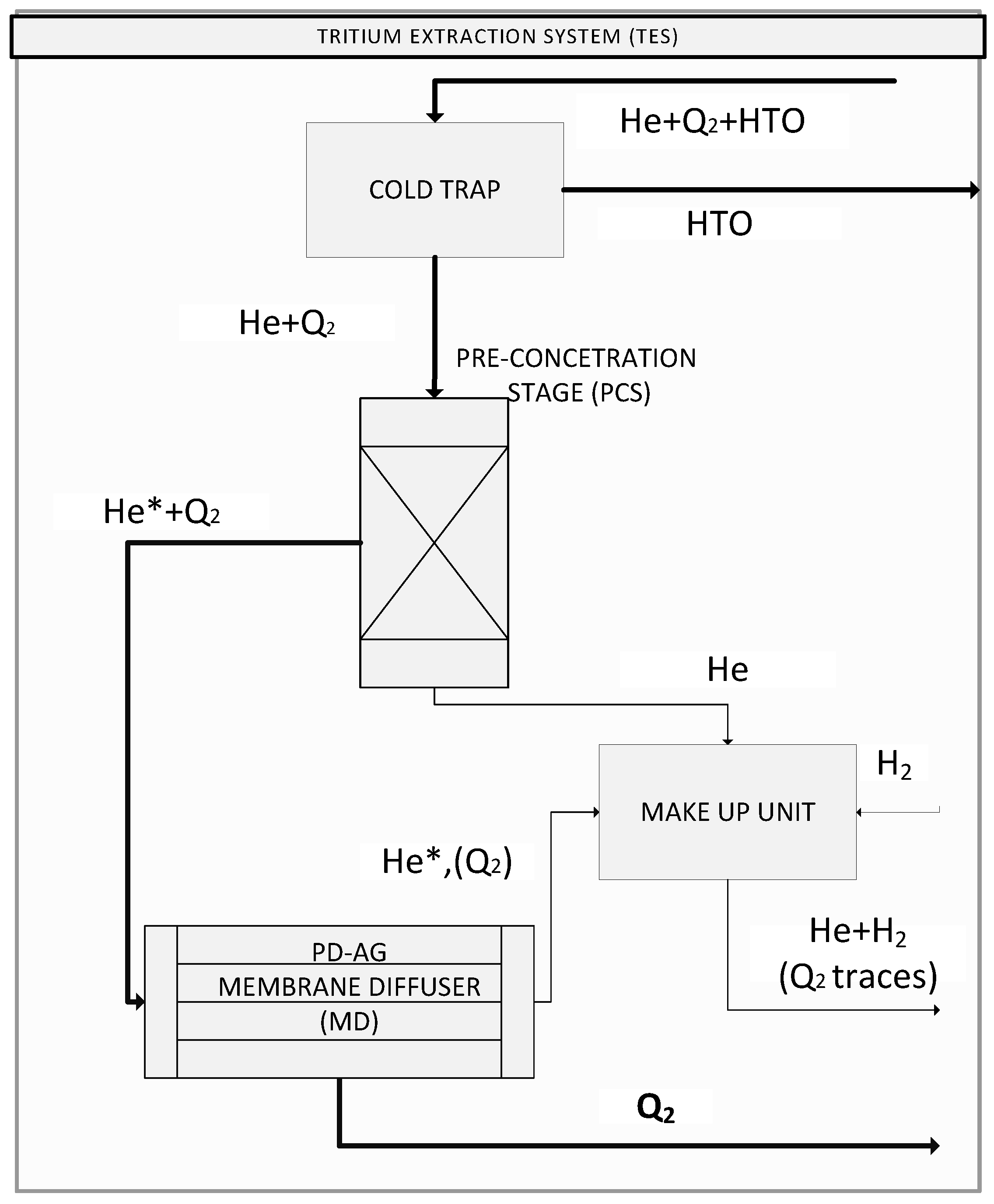
2. Tritium Extraction System for a HCPB Breeding Blanket

Figure 1 provides the simplified view of a tritium plant including the breeding blanket that has been considered for this activity. According to such a scheme, a purge gas (He with a small amount of hydrogen) is used to extract the tritium produced in the breeding blanket. The composition of the gas stream leaving the breeding zone includes He, HT, HTO, and H2. A cold trap (CT) separates the HTO [26,27], which is sent to the water detritiation system (WDS), while the rest of the mixture is sent to a pre-concentration unit (PCS in the Figure 1) for the extraction of the hydrogen isotopes in the form of HT. This stage is necessary because of the very low tritium concentration in the gas mixture that comes out of the breeding blanket. The PCS separates two streams: the first one is rich in hydrogen isotopes and is treated afterwards in a Pd-Ag membrane diffuser and the second one is rich in He.
Two streams leave the extraction system: (i) hydrogen isotopes coming from the permeate side of the Pd-Ag separator which are sent to the inner fuel cycle before being reinjected inside the tokamak; and (ii) a purified He stream that is sent to the breeding blanket through a make-up unit (MU) which restores the hydrogen content required by the breeding blanket.

2.1. Pre-Concentration Stage (PCS)

As previously discussed, the membrane diffuser (separator) is not directly suitable to treat the stream coming out from the breeding blanket due to the very low hydrogen isotopes concentration. For this reason, a pre-concentration stage (PCS) where the tritium is concentrated before going to the membrane unit is mandatory. The best candidate technologies to perform the pre-concentration are: zeolite membrane (ZM), cryogenic molecular sieve bed (CMSB), and getter bed (GB).
Zeolite membranes generally are composed of inorganic and porous alumino-silicate material, which are fully tritium compatible. The KIT Tritium Laboratory (Karlsruhe, Germany) has proposed these zeolite membranes together with the PERMCAT reactor as a new concept for the TES in the HCPB blanket. In this concept, zeolite membranes operate a first separation of the mixture by reducing the He/T molar ratio thanks to the higher selectivity of hydrogen isotopes in respect to helium (the measured selectivity is between 2.2 and 1.4, depending on the operating temperature) [28]. Getter beds are widely used for hydrogen storage and can be applied in the separateion of hydrogen isotopes. In particular, uranium beds exhibit very stable thermodynamic and kinetic properties in absorption and desorption of hydrogen [29]. Another getter bed material proposed for this application is based on the Zr-Co alloy. It uptakes hydrogen at room temperature and releases it when heated to 500–600 K [27]. This kind of getter exhibits excellent performance in terms of both sorption capacity (close to 100%) [30] and hydrogen uploading (H/ZrCo ratio up to 1.8) [31]. Anyway, in all the getter beds the uptake time tends to be minor compared to that of the desorption time; such a characteristic requires the use of several separation units and then an increase of the tritium inventory. Cryogenic molecular sieve beds absorb tritium at low temperature (i.e., liquid nitrogen), while the tritium is released by heating up to 150 K. As reported in the literature [32,33,34], this technology allows for high efficiencies of separation (95%–99%).
The getter beds and the cryogenic molecular sieves must operate in batch mode (simultaneous units in operation and regeneration), while the zeolite membranes can operate continuously. Such a characteristic increases the reliability and, especially, reduces the tritium inventory [28].
Based on these considerations, the zeolite membranes are a very promising technology for the pre-concentration stage even though additional research is still needed. In the following sections, the membrane unit will be designed regardless of the technology used for the pre-concentration stage (that can be identified as a GB, CMSB, or a ZM). The tritium extraction efficiency of this stage will be fixed at 0.95 [30].

2.2. Membrane Diffuser

A membrane diffuser (MD) consisting of a dense metal membrane is capable of selectively separating the hydrogen isotopes. In particular, the membranes considered in this work are Pd-Ag (25 wt. %) alloy tubes in a finger-like configuration.
The mass transfer mechanism of hydrogen through dense metal lattice follows a general expression (4) in which the permeation flux is directly proportional to the difference in hydrogen partial pressure in the upstream and downstream side and inversely proportional to the membrane wall thickness as shown in (4).
F = Φ   ( p up n p down n )   A t
F is the hydrogen permeation flow rate (mol·s−1), Φ is the hydrogen permeability (mol·m−1·s−1·Pan), pup and pdown (Pa) are the hydrogen partial pressures upstream and downstream, respectively, n is the pressure factor, A is the membrane area (m2), and t is the membrane thickness (m). The n factor, when considering hydrogen permeation self-supported Pd-membranes, can be assumed to equal 0.5. Figure 2 provides a better representation of the tritium extraction system (TES) considered in this study by illustrating the gas species entering and leaving each single block (for practical use, the helium in the separated gas stream after the PCS has been indicated as He*). The preliminary design of the membrane diffuser unit represents the main objective of this work.

3. Modelling

In order to estimate the surface area of the membrane diffuser, it is mandatory to calculate the feed flow rate and composition that enters the membrane diffuser. Therefore, two models have been used for the simulations: a simplified TES process model and a membrane permeation model.

3.1. TES Modelling

A simplified model has been built in order to perform the mass balances in each block of the TES, starting from HT and HTO production in the HCPB [35]. The main input data are resumed in Table 1. The characteristics of the stream entering the pre-concentration stage have been assessed by assuming that the HTO is completely separated in the cold trap (CT). The total efficiency of the TES (η TES) in terms of hydrogen isotope separation is the product of the efficiency of the pre-concentration stage (η PCS) and the efficiency of the membrane diffuser (η MD). Only a fraction of the He feeding the PCS, defined as He*/He ratio, is sent to the membrane diffuser.
The assumed values have been chosen considering reasonable operating conditions expected by the technologies adopted.

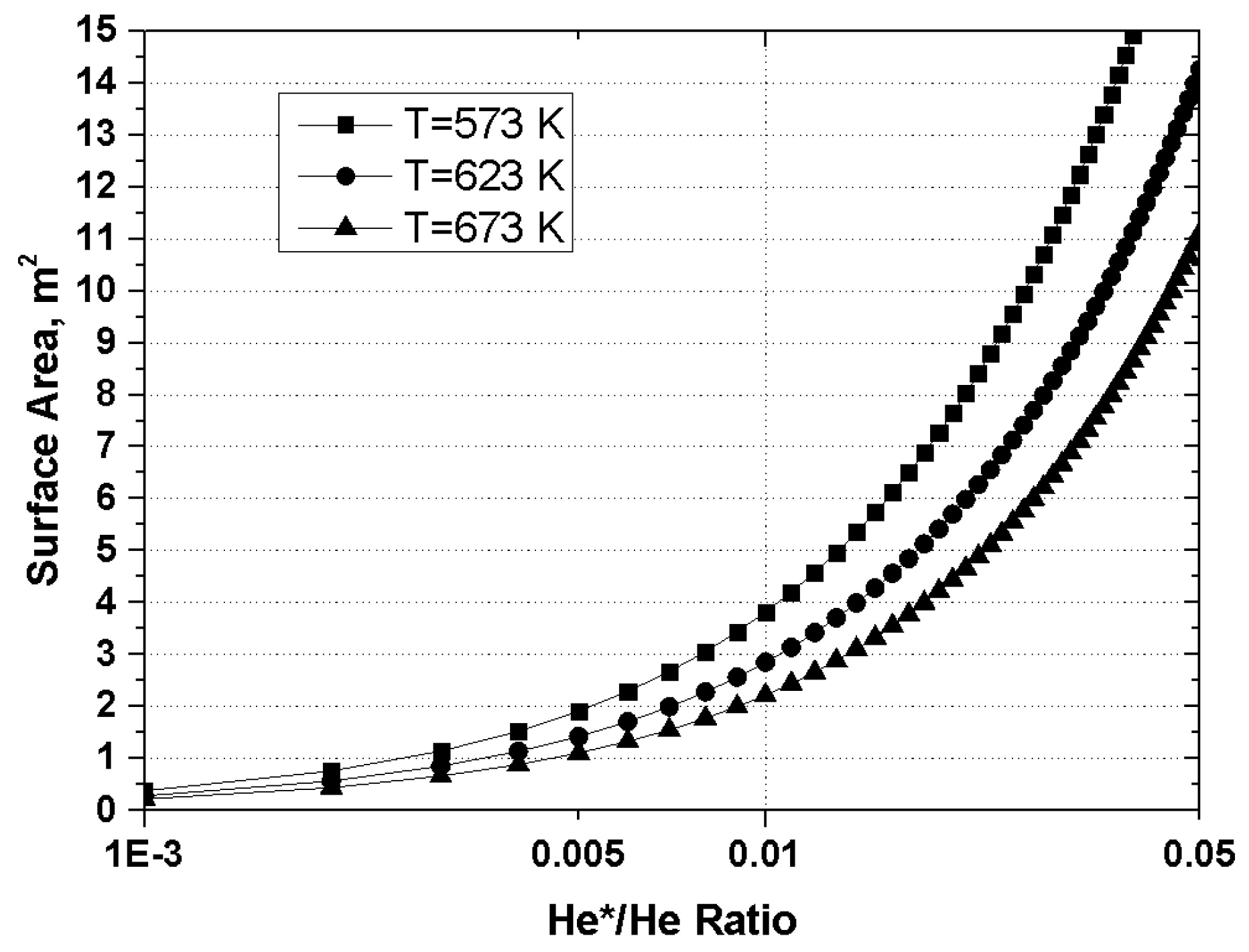
3.2. Pd-Ag Membranes Modelling

The membrane diffuser has been studied by a simplified model based on the mass transfer mechanisms (solubilization, diffusion, and permeation) of the hydrogen into the Pd-alloy metal lattice according to the expression (4) with n = 0.5. The temperature influences the permeation coefficient Pe following an Arrhenius-like trend. The hydrogen permeability values of Pd-Ag membranes at different temperatures have been taken from the literature [36].
The expression (4) shows that by increasing the partial pressure of the hydrogen isotopes, the shell flow rate (permeate) increases, thus, involving a higher separation efficiency and minimizing the required membrane area. Accordingly, the pre-concentration stage of the He stream coming from the blanket allows the design of the Pd-Ag separator to be optimized by significantly reducing the dimensions of the membrane module.
In order to take into account the pressure depletion due to hydrogen permeation, a code developed by ENEA Frascati research center has been used [37,38]. That model simulates both Pd-membrane and membrane reactors for tritium recovery in the applications of the fusion fuel cycle. The membrane device (both Pd-Ag tube and shell module) is divided in finite elements; in each element, the mass balances are performed taking into account the permeation and reaction kinetics. In particular, the permeation of the hydrogen isotopes considers surface reactions together with the diffusion through the metal bulk [38]. The presence of surface reactions reduces the driving force of the permeation by reducing the hydrogen pressure upstream and increasing the hydrogen partial pressure downstream.
J = P e [ ( J K a f + p h f ) 1 2 ( J K a s + p h s ) 1 2 ] d
In Equation (5), J is the permeation flux (mol·m−2·s−1), Pe is the permeability coefficient (mol·m−1·s−1·Pa−0.5), Ka is the hydrogen absorption coefficient over the metal surface (mol·m−2·s−1·Pa−1), ph is the partial pressure of the hydrogen isotope on the metal surface (Pa), and d is the metal thickness (m), while the subscripts f and s indicate the feed and shell side, respectively. In general, it can be observed that the surface effects are negligible for this application because the J K a f ratio in (5) is two order of magnitude less than the hydrogen pressure. For example, considering a membrane thickness of 150 μm and a temperature of 623 K, it is possible to calculate the pressure drop by estimating the Kaf from literature [38]. The resulting value of J K a f is around 1 kPa; it is much lower than phf (18.9–189.0 kPa) and in the range of phs (5 kPa). In particular, the Δpf-s between the feed and the shell side is 184,000 Pa without the surface effects instead of 181,977 Pa with the surface effects.
Such an equation is in an implicit form, thus, it is numerically solved by the simulation code. The model also takes into account the effect of the isotopic competition.
The model has been developed considering the following hypotheses:
  • Very fast radial diffusion (null radial gradient)
  • Steady state condition
  • Perfect gas behavior
  • Mass transfer behavior that follows the Sieverts’ law
  • Total membrane selectivity
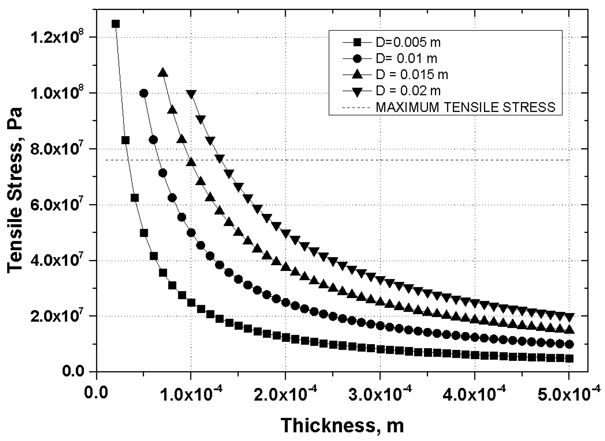
  • The model requires, as input data, the feed gas properties (flow rate, pressure, and composition), the geometry of the tubes (diameter, length, and thickness), and the operating temperature

4. Results and Discussion

Based on the mass balances of the TES system, the flow rate and the composition of the stream feeding the membrane diffuser have been calculated (see Table 2).
Through the simulation, the influence of the operating parameters on the design of the membrane unit has been assessed. Particularly, the required membrane surface, under several operating conditions, has been evaluated for different tube geometries. The membrane area required vs. the tube thickness is reported in Table 3 where a linear relationship between these parameters is shown. Once defined, the overall permeation area, the diameter, and the length of the tubes can be fixed.
The Figure 3, Figure 4 and Figure 5 show the behavior of the membrane area required vs. the lumen pressure, the He*/He ratio, and the shell (permeate) pressure, respectively. This analysis demonstrates that operating at 1 MPa there is no significant difference in the membrane area required by changing the temperature in the range of 623–673 K (Figure 3). Based on these considerations, the membrane unit design has been determined at 1 MPa and 623 K with a membrane area of about 3 m2.
Figure 4 shows that the required membrane area is dramatically affected by the He*/He ratio. In particular, moving above a value of 0.01, the one adopted in the design, small increases of He*/He significantly increase the permeation area required.
To investigate the influence of pshell on the membrane area required, a sensitivity analysis has been reported in Figure 5. It shows that by decreasing the shell pressure and keeping all other parameters constant, the area required significantly decreases until to 4000 Pa. Under 4000 Pa, the decrease of the membrane surface is less appreciable. In this analysis, pshell was assumed to be 5000 Pa.
The wall thickness has been fixed by verifying that the mechanical stress would be acceptable for the mechanical strength of the membrane material. Figure 6 shows the mechanical stress vs. the membrane tube thickness for different diameters; the value of the maximum stress achievable (max tensile stress) is also reported in the graph for comparison. Such a value has been calculated by applying a safety factor of 5 to the ultimate tensile strength of the Pd alloy (380 MPa at 673 K) [36]. Under the operating conditions established above, the Figure 6 reports that a membrane tube of thickness 0.100 mm and a diameter of 10 mm complies with the stress criteria.
Once the membrane area required is calculated, the number of tubes can be determined by considering the effects of the geometric parameters (i.e., tube length) as reported in Figure 7. Practical experience of the manufacturing of membrane modules suggests that adopting a length of 500 mm, which corresponds to 182 tubes in parallel for the selected operating conditions (623 K, 1 MPa).

Membrane Module Configuration

The optimum configuration of the membrane modules has been also investigated. This analysis compared both parallel and series configurations of the multi-tube membrane modules, as shown in Figure 8 and Figure 9, respectively. In both the figures, F is the mass flow rate on the feed (lumen) side while FQ is the shell (permeated) mass flow rate. In practice, the parallel configuration works like one multi-tube membrane diffuser; such a configuration (i.e., splitting of the total number of tubes in several modules in parallel) can be adopted in order to improve the inspectability and maintainability of the membrane unit.
In the series configuration, the efficiency of the first diffuser affects the working conditions of the second diffuser.
Combining the separation efficiency of each single membrane diffuser and taking into account the mass balances, the total efficiency in series configuration can be written as:
η TOT = η 1 + ( 1 η 1 )   η 2
In this expression, ηTOT is the overall efficiency of the configuration, η1 is the efficiency of the first diffuser, and η2 is the efficiency of the second diffuser. The combinations of membrane modules in series reaching a total efficiency between 0.8 and 0.9 are discussed in the comparison with the case of the parallel configuration. In particular, four scenarios of series configurations have been identified and compared with the parallel case at three temperatures as reported in Table 4.
It is evident that the best performance in the series configuration is attained when the first membrane module operates with high efficiency separation (0.8). It is also noteworthy that the third scenario (η1 = 0.68, η2 = 0.5) is more efficient than its opposite, that is the second one (η1 = 0.5, η2 = 0.68). In general, the series configuration requires at least 10% more tubes (or permeation area) in comparison with the corresponding parallel mode.

5. Conclusions

This work exhibits the results of a preliminary design of a Pd-alloy membrane diffuser for tritium extraction from the He purge stream of a HCPB breading blanket. The membrane module has been designed and optimized under the operating conditions of a DEMO-like reactor.
By introducing a membrane diffuser directly downstream of the cold trap (see the TES system), a preliminary study has shown that a diffuser consisting of self-supported membranes could not efficiently treat the stream coming from the breeding blanket because of its very low tritium concentration. In fact, in this case, the gas mixture feeding the membrane unit is composed of 99.80 mol% of He and 0.198 mol% of purge H2, while the HT concentration is 0.0012 mol%. This means that a very large permeation area should be necessary for recovering the tritium in agreement with the DEMO reactor design requirements. Thus, a pre-concentration before the membrane diffuser has been proposed which could be operated via some technology under study (for e.g., zeolite membranes, cryogenic molecular sieve beds, getter beds).
Based on this process option, by reducing the helium content by two orders of magnitude (He*/He = 0.01) through a pre-concentration stage, a membrane area of 2.85 m2 has been assessed as suitable for a DEMO-like reactor operating at 1 MPa and 623 K. By optimizing the membrane tubes geometry through the criterion of the mechanical resistance, each membrane tube should have a diameter of 10 mm, a length of 500 mm, and a thickness of 0.1 mm. This means that 182 Pd-Ag tubes will be required for the membrane diffuser module.
Series and parallel configurations of membrane modules have also been simulated. The results of the analysis demonstrate that the series configuration decreases the overall efficiency because the second diffuser receives a stream that is too depleted in hydrogen; even if the hydrogen recovery is more incisive, such a configuration requires a larger number of tubes. The parallel configuration is characterized by higher efficiency and it works well in cases of higher flow rates.

Author Contributions

Marco Incelli wrote the article and carried out the calculations. Silvano Tosti and Alessia Santucci gave the main contribution in the introduction and conclusion. Maurizio Carlini gave his main contribution in the review and activity coordination.

Conflicts of Interest

The authors declare no conflict of interest.

References

  1. International Energy Outlook 2016—World Energy Demand and Economc Outlook—Energy Information Administration. Available online: http://www.eia.gov/forecasts/ieo/world.cfm (accessed on 1 September 2016).
  2. Matthews, G.F.; Beurskens, M.; Brezinsek, S.; Groth, M.; Joffrin, E.; Loving, A.; Kear, M.; Mayoral, M.; Neu, R.; Prior, P.; et al. JET ITER-like wall—Overview and experimental programme. Phys. Scr. 2011, 2011, 14001. [Google Scholar] [CrossRef]
  3. Paméla, J.; Matthews, G.F.; Philipps, V.; Kamendje, R. An ITER-like wall for JET. J. Nucl. Mater. 2007, 363–365, 1–11. [Google Scholar] [CrossRef]
  4. Maisonnier, D.; Campbell, D.; Cook, I.; di Pace, L.; Giancarli, L.; Hayward, J.; Puma, A.L.; Medrano, M.; Norajitra, P.; Roccella, M.; et al. Power plant conceptual studies in Europe. Nucl. Fusion 2007, 47, 1524. [Google Scholar] [CrossRef]
  5. Ihli, T.; Basu, T.K.; Giancarli, L.M.; Konishi, S.; Malang, S.; Najmabadi, F.; Nishio, S.; Raffray, A.R.; Rao, C.V.S.; Sagara, A.; et al. Review of blanket designs for advanced fusion reactors. Fusion Eng. Des. 2008, 83, 912–919. [Google Scholar] [CrossRef]
  6. Poitevin, Y.; Boccaccini, L.V.; Zmitko, M.; Ricapito, I.; Salavy, J.-F.; Diegele, E.; Gabriel, F.; Magnani, E.; Neuberger, H.; Lässer, R.; et al. Tritium breeder blankets design and technologies in Europe: Development status of ITER Test Blanket Modules, test & qualification strategy and roadmap towards DEMO. Fusion Eng. Des. 2010, 85, 2340–2347. [Google Scholar]
  7. Giancarli, L.; Chuyanov, V.; Abdou, M.; Akiba, M.; Hong, B.G.; Lässer, R.; Pan, C.; Strebkov, Y. Test blanket modules in ITER: An overview on proposed designs and required DEMO-relevant materials. J. Nucl. Mater. 2007, 367–370, 1271–1280. [Google Scholar] [CrossRef]
  8. Bachmann, C.; Aiello, G.; Albanese, R.; Ambrosino, R.; Arbeiter, F.; Aubert, J.; Boccaccini, L.; Carloni, D.; Federici, G.; Fischer, U.; et al. Initial DEMO tokamak design configuration studies. Fusion Eng. Des. 2015, 98–99, 1423–1426. [Google Scholar] [CrossRef]
  9. Rizzello, C.; Tosti, S. Overview of the tritium system of Ignitor. Fusion Eng. Des. 2008, 83, 594–600. [Google Scholar] [CrossRef]
  10. Demange, D. Advanced tritium extraction process for HCPB breeding blanket. In Proceedings of the 17th IEA International Workshop on Ceramic Breeder Blanket Interactions (CBBl-17), Barcelona, Spain, 12–14 September 2013.
  11. Knitter, R.; Boccaccini, L.V.; Ibarra, A. Tritium release, extraction and permeation. In Proceedings of the 17th IEA International Workshop on Ceramic Breeder Blanket Interactions (CBBl-17), Barcelona, Spain, 12–14 September 2013; KIT Scientific Reports, 7654. KIT Scientific Publishing: Karlsruhe, Germany, 2014. [Google Scholar]
  12. Paglieri, S.N.; Way, J.D. Innovations in Palladium Membrane Research. Sep. Purif. Rev. 2002, 31, 1–169. [Google Scholar] [CrossRef]
  13. Shu, J.; Grandjean, B.P.A.; Neste, A.V.; Kaliaguine, S. Catalytic palladium-based membrane reactors: A review. Can. J. Chem. Eng. 1991, 69, 1036–1060. [Google Scholar] [CrossRef]
  14. Uemiya, S. State-of-the-Art of Supported Metal Membranes for Gas Separation. Sep. Purif. Rev. 1999, 28, 51–85. [Google Scholar] [CrossRef]
  15. Moulijn, J.A.; Stankiewicz, A.I.; Schramm, O.; Seidel-Morgenstern, A. 1st International symposium on multifunctional reactorsComparing porous and dense membranes for the application in membrane reactors. Chem. Eng. Sci. 1999, 54, 1447–1453. [Google Scholar]
  16. Wu, L.-Q.; Xu, N.; Shi, J. Preparation of a Palladium Composite Membrane by an Improved Electroless Plating Technique. Ind. Eng. Chem. Res. 2000, 39, 342–348. [Google Scholar] [CrossRef]
  17. Tosti, S.; Bettinali, L.; Castelli, S.; Sarto, F.; Scaglione, S.; Violante, V. Sputtered, electroless, and rolled palladium-ceramic membranes. J. Membr. Sci. 2002, 196, 241–249. [Google Scholar] [CrossRef]
  18. Shu, J.; Grandjean, B.P.A.; Ghali, E.; Kaliaguine, S. Simultaneous deposition of Pd and Ag on porous stainless steel by electroless plating. J. Membr. Sci. 1993, 77, 181–195. [Google Scholar] [CrossRef]
  19. Tosti, S.; Bettinali, L. Diffusion bonding of pd-ag rolled membranes. J. Mater. Sci. 2004, 39, 3041–3046. [Google Scholar] [CrossRef]
  20. Ackerman, F.J.; Koskinas, G.J. Permeation of hydrogen and deuterium through palladium-silver alloys. J. Chem. Eng. Data 1972, 17, 51–55. [Google Scholar] [CrossRef]
  21. Yoshida, H.; Konishi, S.; Naruse, Y. Preliminary Design of a Fusion Reactor Fuel Cleanup System by the Palladium-Alloy Membrane Method. FST 1983, 3, 471–484. [Google Scholar]
  22. Glugla, M.; Penzhorn, R. Proceedings of the Third International Symposium on Fusion Nuclear Technology Development of fusion fuel cycle technology at the Tritium Laboratory Karlsruhe: the experiment CAPRICE. Fusion Eng. Des. 1995, 28, 348–356. [Google Scholar] [CrossRef]
  23. Birdsell, S.A.; Willms, R.S. Tritium recovery from tritiated water with a two-stage palladium membrane reactor. Fusion Eng. Des. 1998, 39–40, 1041–1048. [Google Scholar] [CrossRef]
  24. Tosti, S.; Bettinali, L.; Violante, V.; Basile, A.; Chiappetta, M.; Criscuoli, A.; Drioli, E.; Rizzello, C. Pd Based Ultrathin Membranes for the Tritiated Water Gas Shift Reaction in the ITER Breeder Recovery System; Fusion Technology: Marseille, France, 1998; Vol. 2, pp. 1033–1036. [Google Scholar]
  25. Tosti, S.; Rizzello, C. 24—Membranes for nuclear power applications. In Advanced Membrane Science and Technology for Sustainable Energy and Environmental Applications; Woodhead Publishing Series in Energy; Woodhead Publishing: New Delhi, India, 2011; pp. 769–791. [Google Scholar]
  26. Tosti, S.; Nicholas, G. (Eds.) Tritium in Fusion: Production, Uses and Environmental Impact; 9781624172700 Hardcover—Revaluation Books; Nova Science Publishers: New York, NY, USA, 2013; Available online: http://www.abebooks.co.uk/Tritium-Fusion-Production-Uses-Environmental-Impact/17328606312/bd (accessed on 4 October 2016).
  27. Ciampichetti, A.; Nitti, F.S.; Aiello, A.; Ricapito, I.; Liger, K.; Demange, D.; Sedano, L.; Moreno, C.; Succi, M. Conceptual design of Tritium Extraction System for the European HCPB Test Blanket Module. Fusion Eng. Des. 2012, 87, 620–624. [Google Scholar] [CrossRef]
  28. Borisevich, O.; Antunes, R.; Demange, D. Experimental study of permeation and selectivity of zeolite membranes for tritium processes. Fusion Eng. Des. 2015, 98–99, 1755–1758. [Google Scholar] [CrossRef]
  29. Sedano, L.A. Tritium Cycle Design for He-cooled Blankets for DEMO; Laboratorio Nacional de Fusión por Confinamiento Magnético, CIEMAT: Madrid, Spain, 2007. [Google Scholar]
  30. Mannone, F. Safety in Tritium Handling Technology; Springer Science & Business Media: Berlin, Germany, 2012. [Google Scholar]
  31. Beloglazov, S.; Glugla, M.; FanghÃnel, E.; Perevezentsev, A.; Wagner, R. Performance of a Full-Scale ITER Metal Hydride Storage Bed in Comparison with Requirements. FST 2008, 54, 22–26. [Google Scholar]
  32. Mannone, F. (Ed.) Safety in Tritium Handling Technology; Eurocourses: Nuclear Science and Technology; Springer: Dordrecht, The Netherlands, 1993; Volume 1.
  33. Penzhorn, R.-D.; devillers, M.; Sirch, M. Evaluation of ZrCo and other getters for tritium handling and storage. J. Nucl. Mater. 1990, 170, 217–231. [Google Scholar] [CrossRef]
  34. Bekris, N.; Caldwell-Nichols, C.; Hutter, E. Cold trap and cryogenic molecular sieve adsorber: Components for tritium extraction from the purge gas of the HCPB-breeder blanket for ITER. Fusion Eng. Des. 2003, 69, 21–25. [Google Scholar] [CrossRef]
  35. Demange, D.; Wagner, R.; Franza, F.; Tosti, S.; Santucci, A.; Ciampichetti, A. DAS Design Assessment Studies—In-Vessel Component Design and Interaction; EFDA, 2012; p. 97. [Google Scholar]
  36. Tosti, S.; Bettinali, L.; Violante, V. Rolled thin Pd and Pd–Ag membranes for hydrogen separation and production. Int. J. Hydrogen Energy 2000, 25, 319–325. [Google Scholar] [CrossRef]
  37. Violante, V.; Tosti, S.; Colombini, A.; Castelli, S.; de Francesco, M. Experimental confirmation of thetheoretical previsions for the applicability of catalytic membrane reactors for the fusion fuel cycle. Fusion Technol. 1996, 2, 1205–1208. [Google Scholar]
  38. Vadrucci, M.; Borgognoni, F.; Moriani, A.; Santucci, A.; Tosti, S. Hydrogen permeation through Pd–Ag membranes: Surface effects and Sieverts’ law. Int. J. Hydrogen Energy 2013, 38, 4144–4152. [Google Scholar] [CrossRef]
Figure 1. Block diagram of the fuel cycle in DEMO for a helium cooled pebble bed (HCPB) blanket.
Processes 04 00040 g001
Figure 2. Block diagram of TES that includes a pre-concentration stage (PCS) and a membrane diffuser (MD).
Processes 04 00040 g002
Figure 3. Membrane surface area vs. the lumen pressure at different temperatures with a shell (permeate) pressure of 5 kPa.
Processes 04 00040 g003
Figure 4. Membrane area required vs. the He/T feed ratio at different temperatures and 1 MPa of lumen pressure and 5 kPa of shell pressure.
Processes 04 00040 g004
Figure 5. Membrane area required vs. the shell (permeate) pressure at different temperatures and 1 MPa of lumen pressure.
Processes 04 00040 g005
Figure 6. Tensile stress values vs. the membrane thickness for different tube diameters at 623 K and 1 MPa lumen pressure.
Processes 04 00040 g006
Figure 7. Number of tubes vs. length for different thickness values at 623 K, 1 MPa pressure, and a tube diameter of 10 mm.
Processes 04 00040 g007
Figure 8. Parallel multi-tube membrane modules.
Processes 04 00040 g008
Figure 9. Series of multi-tube membrane modules.
Processes 04 00040 g009
Table 1. Input data.
ParameterValueReference
Tritium production (g·d−1)365[35]
He purge flow rate (kg·h−1)1440[35]
He purge pressure (MPa)0.11[35]
Doping ratio (H2/He) (wt. %)0.10[35]
η TES (-)0.80[35]
HT partial pressure in He (Pa)1.1[35]
HTO partial pressure in He (Pa)0.031[35]
Assumed Values
η PCS (-)0.95
η MD (-)0.84
He*/He ratio0.01
pshell (kPa)5
MD lumen pressure (MPa)1
Table 2. Membrane diffuser feed flow rates.
Gas SpeciesMass Flow Rate (kg·h−1)Volumetric Flow Rate (Nm3·h−1)
He*14.40080.690
HT0.01370.0760
H21.36815.179
Table 3. Permeation area required for different thicknesses of the membrane tubes at 623 K.
Thickness (m)Area (m2)
5.00 × 10−51.43
1.00 × 10−42.85
1.50 × 10−44.28
Table 4. Number of tubes required in parallel and series configuration (10 mm diameter, 500 mm length, 0.1 mm thickness).
PARSERIES
Tη10.840.20.50.680.8
η2-0.80.680.50.2
573 K1st DIFFUSER24461152183228
2nd DIFFUSER-20914110938
TOT244270293292266
623 K1st DIFFUSER18245114136170
2nd DIFFUSER-20914110938
TOT182255254245208
673 K1st DIFFUSER1423588106133
2nd DIFFUSER-20914110938
TOT142245229215171

