1. Introduction
Distillation column is one of the most important separation facilities in the process industry. Distillation necessitates considerable energy investments, as it is reported that distillation can account for more than 50% of plant operating cost [
1]. There is ample scope for developing more energy efficient distillation schemes, one of which is dividing wall column (DWC).
For the sharp separation of a multi-component mixture, one always adopts a sequence of distillation columns. For example, at least two columns are used in either direct or indirect sequence for the separation of a three-component mixture.
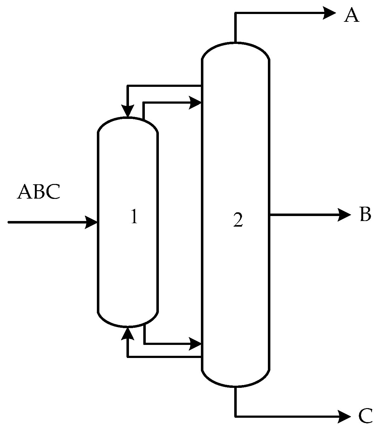
Figure 1 shows an energy efficient configuration for separating a three components mixture (Petlyuk configuration [
2]). In this configuration, the vapor and liquid streams leaving the first column are directly connected with the second column. The first column is called the pre-fractionator and the second is the main column. In this case, a mixture containing A, B and C (in decreasing order of volatilit) first enters the pre-fractionator, sharp separation happens between light component A and heavy component C, while the middle component B is distributed naturally between the top and bottom of the pre-fractionator [
2]. Then, a further separation is performed to obtain high-purity individual components at the top, middle and bottom of the main column.
It is reported that the Petlyuk configuration can save up to 30% of operational cost [
3], in comparison with the conventional direct or indirect sequencing. The improvement of thermodynamic efficiency originates from two sources: (1) the Petlyuk column avoids the remixing of the middle components happening in the conventional column sequence [
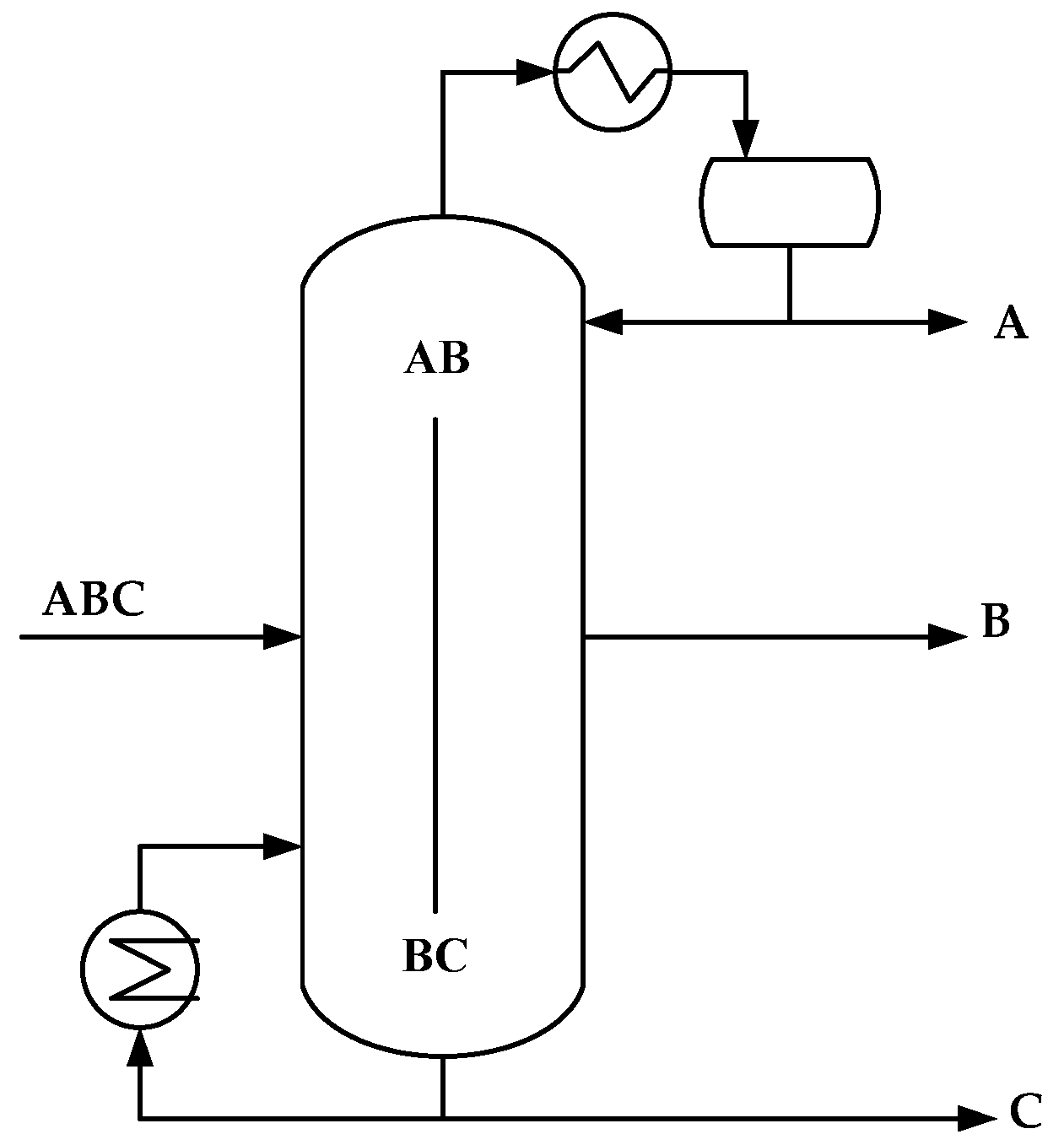
4]; and (2) the condenser and reboiler downsize to one for a three-component separation system, which saves both energy cost and capital cost. To make the Petlyuk configuration compact, the two columns in
Figure 1 are accommodated in one shell, which formulates the DWC, as shown in
Figure 2. By inserting an internal, vertical partition wall into the column, the two sections of the DWC function as two columns in
Figure 1, but one can easily conjecture that DWC needs less capital investment than the Petlyuk configuration.
The first patent related to DWC was granted to Wright in 1949 [
5], but wide acceptance of DWC in industry did not happen until the 1980s, when the first industrial application of DWC was implemented by BASF (i.e., Baden Aniline and Soda Factory, a German chemical company) [
6]. The reason for delayed recognition/acceptance by both academic and industrial communities is that DWC has more complex structure than the conventional one, which leads to more design parameters and makes the dynamics of the DWC more difficult to follow. Since the success of its application, DWC has gradually obtained wide recognition. By 2010, over 100 DWC applications were facilitated worldwide [
7], prominent among which are catalytic product recovery by a dividing wall debutanizer column [
8] (UOP, i.e., Universal Oil Products, a US chemical company) and high-purity 2-ethylhexyl-acrylate [
9] and neopentyl glycol [
10] preparation using the DWC (LG Chem, i.e., a Korean chemical company). In academia, DWCs are studied to conduct azeotropic, extractive, and reactive distillation. Kiss et al. [
11] proposed an innovative dimethyl ether synthesis process based on a reactive DWC, in which a reactive distillation unit was effectively conducted in one DWC. By their accounts, the integrated reactive DWC outperformed conventional or reactive distillation schemes by significant saving energy of 12–58%, reducing CO
2 emissions up to 60%, and lowering total annual costs up to 30%. Lan-Yi et al. [
12] proposed the DWC for heterogeneous azeotropic distillation using cyclohexane as an entrainer for ethanol dehydration, by which an energy saving of 42.17% and total annual cost reduction of 35.18% were achieved. Kiss and Ignat [
13] applied a extractive DWC to concentrate and dehydrate bio-ethanol in one step, with ethylene glycol as mass separating agent.
However, due to increased design parameters, it has been rather difficult to design, model and simulate DWCs. Although the MultiFrac unit of Aspen Plus can be used to model the Petlyuk configurations, simulation modules exclusively for DWC are still not available in commercial process simulators such as Aspen Plus, HYSYS, or ChemCAD [
1,
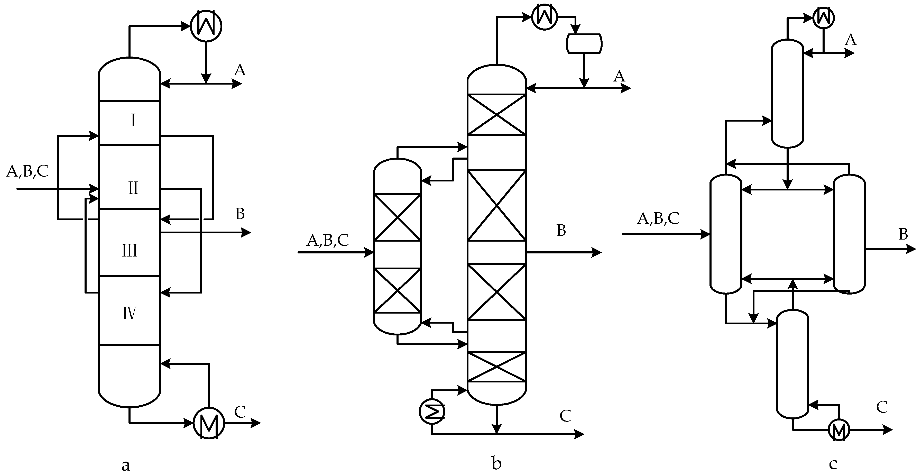
7]. Moreover, the Petlyuk model in Aspen Plus is not flexible for customized modification due to its closed software environment. In practice, a DWC unit is always modeled as a sequence of simple column sections, for example the pump-around model, the two-column sequence model and the four-column sequence model [
1,
7], as shown in
Figure 3a–c, respectively. Once the models mentioned above approximate a typical DWC, its structure is partitioned deliberately and some of the internal relations are exposed as decision variables, which increase the number of dimensions overall and complicate the problem. Furthermore, most of the previously mentioned simulators implement the sequential modular (SM) approach, which adopts the iteration-and-convergence solving strategy. Both increasing the dimension and adopting the SM approach cause the simulator to work with high computational cost.
To tackle the problems above, a rigorous DWC model was developed in the general process modeling system (gPROMS) environment (Imperial College London, Process System Enterprise Ltd., London, UK, Version 4.0). gPROMS software is a flexible, open source and user-friendly platform, especially suitable for modeling unconventional or complex process systems, such as the catalyst activity reduction [
14], the emulsion polymerization reaction [
15] or the dynamics of the non-equilibrium, three-phase separation [
16]. One of the key advantages of the gPROMS platform is that it adopts the equation-oriented (EO) approach to solve the problem. As for the DWC case, the decision variables and state variables are treated equally, which further provides high flexibility and efficiency for solving the design and optimization problems related to the DWC design. Moreover, the platform enables easy extrapolation to modeling more complex DWC with multiple partitioning walls.
In this paper, a rigorous DWC model is proposed based on the equilibrium stage assumption, which may be used as a standard DWC module for further development. The rigorous DWC modeling is detailed in
Section 2. Then, the proposed model was tested and validated (against literature data) by separation of a ternary mixture of benzene–toluene–xylene (BTX), as presented in
Section 3. Based on the case study, some of the general features about the DWC can be properly outlined and easily studied with this rigorous DWC model. For example, the liquid and vapor split ratio are key design parameters for the DWC, which can be studied similarly to other parameters by our proposed model, whereas, in the “equivalent model” (as shown in
Figure 3), they are exposed as decision variables, and one testing point needs a full procedure of initial guess, iteration and convergence. Hence, we present the DWC analysis on three key indicators for designing and assessment purposes: the liquid and vapor split ratio, the middle component split ratio and the degree of mixing. Finally, conclusions are drawn about the DWC based on the proposed model in
Section 4.
2. Materials and Methods
As mentioned above, most existing models for the DWC are based on the combination of conventional columns, which is only thermodynamically equivalent to the DWC. Here, a rigorous DWC model is established based on the following assumptions:
- (1)
At each stage, the vapor and liquid reach their equilibrium right after their contacting, so the vapor and liquid leaving this stage are at equilibrium state.
- (2)
The number of stages on both sides of the dividing wall is identical; hence, the pressure drop is uniform across each stage.
- (3)
The heat transfer across the dividing wall is ignored.
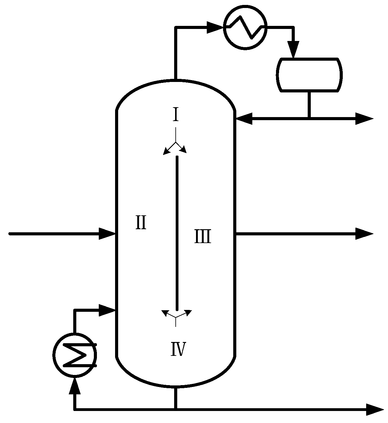
For modeling purpose, the DWC is considered to incorporate four main sections as shown in
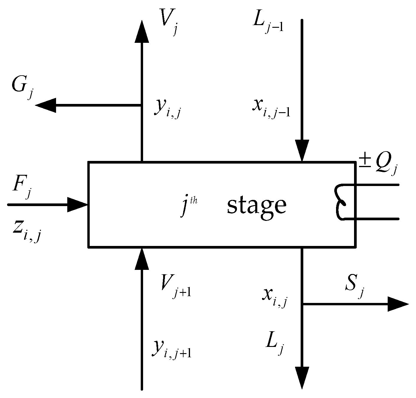
Figure 4. I section is the public rectifying section, II is actually the pre-fractionator, III is the main column, and IV is the public stripping section. A typical schematic representation of a generic stage is shown in
Figure 5. Each stage contains mass, enthalpy balance equations, phase equilibrium equations and summary equations (MESH). The corresponding equations for the
jth-stage are given below:
1. Mass balance equations
where
F is feed flow rate;
L and
V are the flow rates in liquid and vapor phases;
S and
G are the side-draw flow rates in liquid and vapor phases;
xi is liquid fraction; and
yi is vapor fraction.
2. Phase equilibrium equations
where
K is phase equilibrium constant, which can be obtained by a suitable thermodynamic equation of state.
3. Enthalpy balance equations
where
HF is the enthalpy of feed stream; and
HV and
HL are the enthalpy of vapor and liquid.
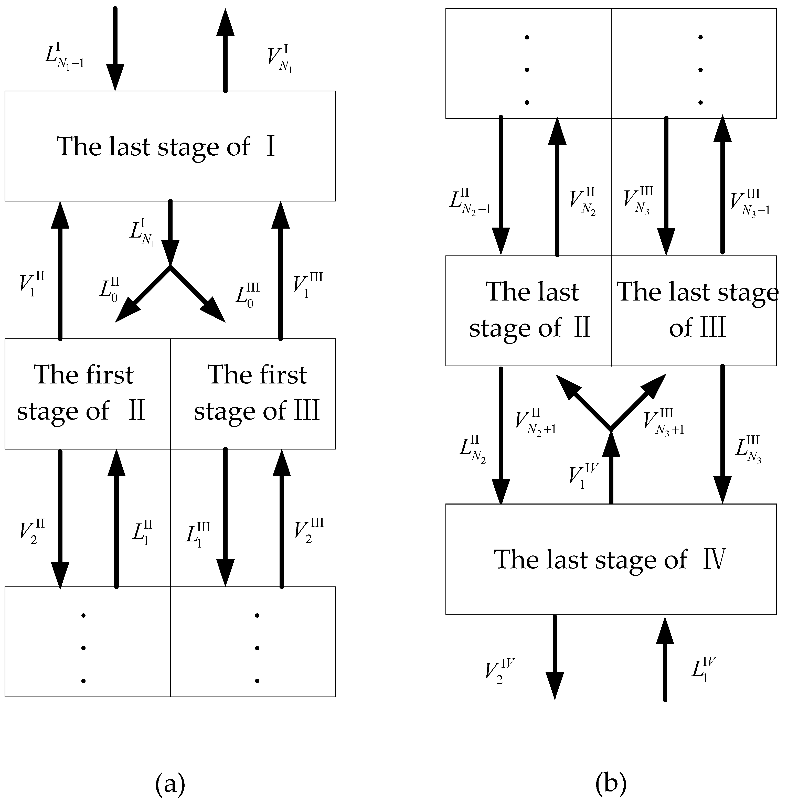
Equations (1)–(6) are generally suitable for each stage within the four sections. As shown in
Figure 3, the last stage of I section and the first stage of IV need special consideration, because they are accompanied with the splitting and mixing of the liquid and vapor streams. As shown in
Figure 6a, above the dividing wall, the liquid from I splits into two streams, and one goes to the pre-fractionator while the other goes to the main column. The vapor leaving the first stage of both II and III goes to I and mixes. Similarly, in
Figure 6b, below the dividing wall, the vapor stream from IV splits as well, and enters the pre-fractionator and main column. The liquid leaving the last stage of II and III goes to IV and mixes. Concentration and temperature remain unchanged after splitting [
17] for split streams.
Above the dividing wall, the liquid from the last stage of I is splits into two streams, one enters the pre-fractionator, while the other going to the main column. That means,
where
represents the total liquid flow from the last stage of I, and
and
represent the liquid streams which enter the first stage of II (pre-fractionator) and III (main column), respectively. The liquid split ratio is defined accordingly as:
Below the dividing wall, the vapor stream from the first stage of IV splits into two streams, one goes to the pre-fractionator, and the other enters the main column.
where
represents the total vapor stream from the first stage of IV, and
and
represent the vapor streams which enter the last stage of II and III, respectively. Here, the vapor split ratio is defined as:
As the vapor streams from both sides of the dividing wall are mixed, the material and enthalpy balance equations of the last stage of I are different from other stages, and can be described as follows,
where
L and
V are the flow rates in liquid and vapor phases, and
HV and
HL are the enthalpy of vapor and liquid.
As the liquid streams from both ends of the dividing wall are mixed, the material and enthalpy balance equations of the first stage of Section IV are different from other stages and can be described as follows,
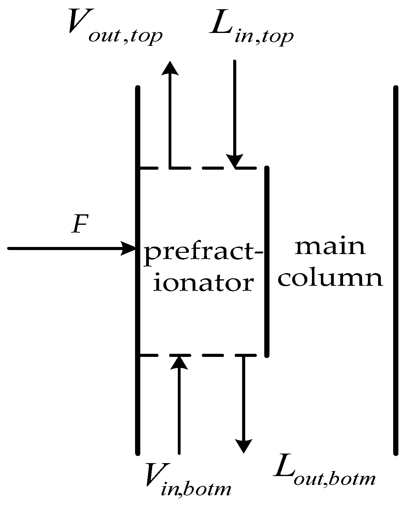
It is interesting to investigate how each component moves through the column sections towards the products. According to the Mueller and Kenig [
18], another important parameter
RB,top, the middle component split ratio at the top of the pre-fractionator, is defined as:
Accordingly, the middle component split ratio at the bottom of the pre-fractionator is defined as:
As shown in
Figure 7,
and
represent the outlet vapor flowrate and inlet liquid flowrate at the top of the pre-fractionator;
and
represent the middle component mole fractions of the corresponding streams;
and
represent the outlet liquid and inlet vapor flowrate at the bottom of the pre-fractionator, respectively;
and
represent the middle component mole fractions of the corresponding streams. From Equations (15) and (16), parameters
and
are related to the liquid and vapor split ratio. Note that the summation of
and
is 1. Thus, if one parameter is known, the other can be readily determined.
Mixing streams with different compositions, which occurs at stages of I and IV right next to the dividing wall, means changes of the monotonic property of each component within II and III (typically, a weighted average of that from both sides). This inevitably accompanies with an increase in entropy, which is an intrinsic source of thermodynamic inefficiency of the separation process occurring in the DWC [
1,
7,
19]. To measure the mixing effect at both ends of the dividing wall, the liquid and vapor mixing degree need to be assessed. In this paper, we define the degree of liquid mixing as the quadratic sum of liquid concentration difference for the three components at the bottom of the dividing wall, and similarly the degree of vapor mixing is defined as the quadratic sum of the vapor concentration difference for the three components at the top of the wall indicates,
The solution of the rigorous model of the DWC described in previous section (Equations (1)–(14)) requires definition of a number of parameters: the number of stages in the four different sections of the column, the locations of the feed and side-draw, feed condition and the position of the dividing wall [
19].
2.1. Case Description
A ternary feed mixture of Benzene (A), Toluene (B) and p-Xylene (C) was used as the case study. The flowrate was set as 1 kmol/s, feeding temperature as 358 K, and the composition ratio was 30:30:40 mol% for A:B:C. A DWC was implemented for separation of the three components with molar purity up to 99 mol% by each.
According to Luyben [
20], there are four sections in the DWC (as shown in
Figure 4), 12 stages for I and IV, and 24 stages for II and III. The feed steam was introduced at Stage 12 of II in the pre-fractionator, the middle component was extracted from the main column at the side-draw of Stage 11 in III, and the reflux ratio was set as 2.62.
2.2. Model Validation
Based on the configuration described above, the DWC model proposed in this paper was adopted to separate the ternary mixture of benzene, toluene and o-xylene, with 99 mol% product purities.
Table 1 presents the simulation results, which are compared with those of Luyben [
20].
As shown in
Table 1, the simulation result by our model shows an excellent agreement with those of Luyben [
20]. We also cross-validated the simulation results with other process simulation platform, e.g., Aspen Plus (Version 7.1, Aspen Technology, Inc., Burlington, MA, USA, 2009). After a few tests on different thermodynamic models or other ternary species separation cases, we rendered that the model we developed is mathematically correct in describing the DWC process, and further analysis based on this model is presented in the next section.
3. Results and Discussion
The DWC has the prominent feature of energy saving compared to the conventional columns, which makes it a problem for the assessment of its energy efficiency. The rigorous DWC model developed in this paper enables implementing the assessment procedure simply. Based on the case study introduced previously, three key indicators, the liquid and vapor split ratio, the middle component split ratio and the degree of mixing, are discussed in detail as follows. Note that not all indicators are mandatory for a specific DWC application. We incorporated all of them to both test our DWC model and outline the general properties of a DWC at different angles.
3.1. The Effect of Liquid and Vapor Split Ratio
As defined in
Section 2, vapor split ratio is the vapor flowrate entering the pre-fractionator against the total vapor flowrate, and the liquid split ratio is the liquid flowrate entering the pre-fractionator against the total liquid flowrate. The split and mix of liquid and vapor flows from both sides of the dividing wall take place at both ends of the wall, which can be adjusted by proper positioning of the dividing wall, or by shifting the capacity from one side to the other.
The liquid and vapor split ratio affects the separation performance and energy efficiency of a DWC. If the liquid or vapor split ratio is too low, it means that large amount of vapor flow or liquid flow enters the main column. If the liquid or vapor split ratio is too high, it means that large amount of vapor flow or liquid flow enters the pre-fractionator. As these cases are similar with the separation of three components in a conventional distillation, the split ratios considered were within the range from 0.35 to 0.66.
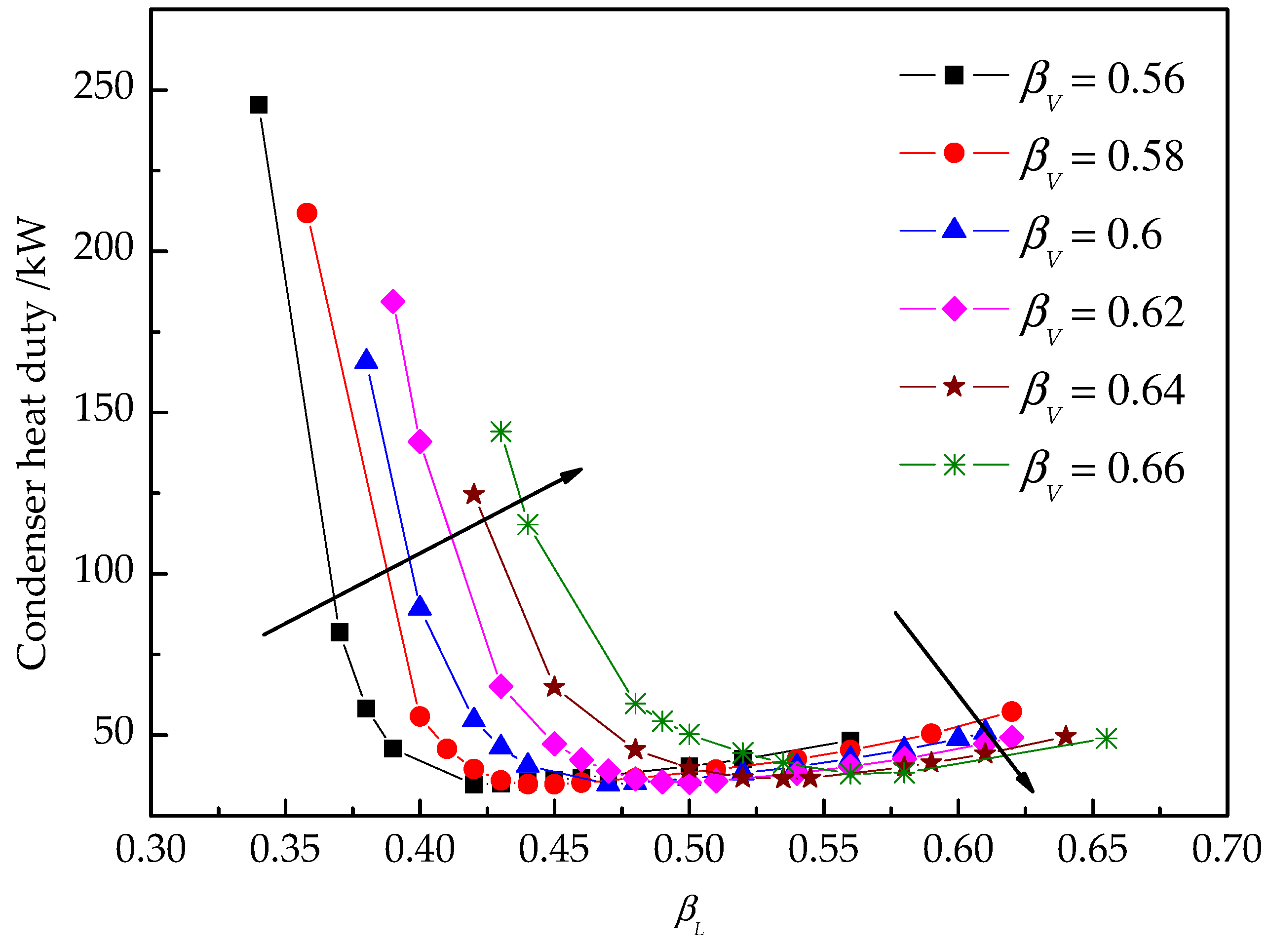
For specified separation requirement and DWC configuration, the performance depends on its energy consumption at the steady state, i.e., heat duties of reboiler and condenser (neglects energy loses elsewhere).
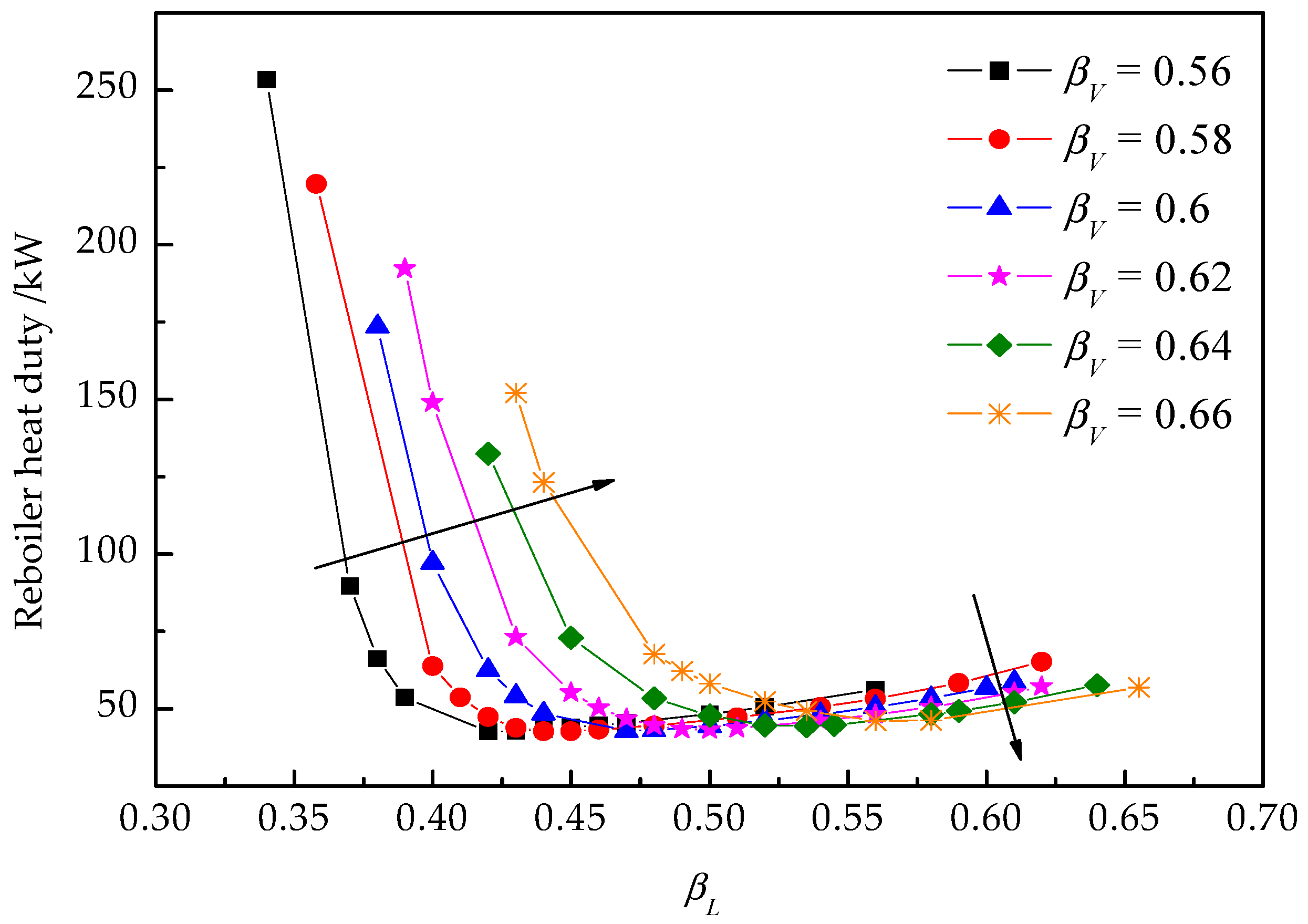
Figure 8 and
Figure 9 illustrate the reboiler and condenser heat duties under different liquid and vapor split ratios.
For a specified vapor split ratio
βV, the reboiler heat duty varies with the change of the liquid split ratio
βL, i.e., when the vapor split ratio
βV is 0.56 in
Figure 8, the heat duty of the reboiler decreases first, and then increases with the increase of
βL after reaching its minimum value of 0.43. Hence, an optimal liquid split ratio exists to reduce the reboiler duty to minimum when the vapor split ratio is specified. In accordance with the result in
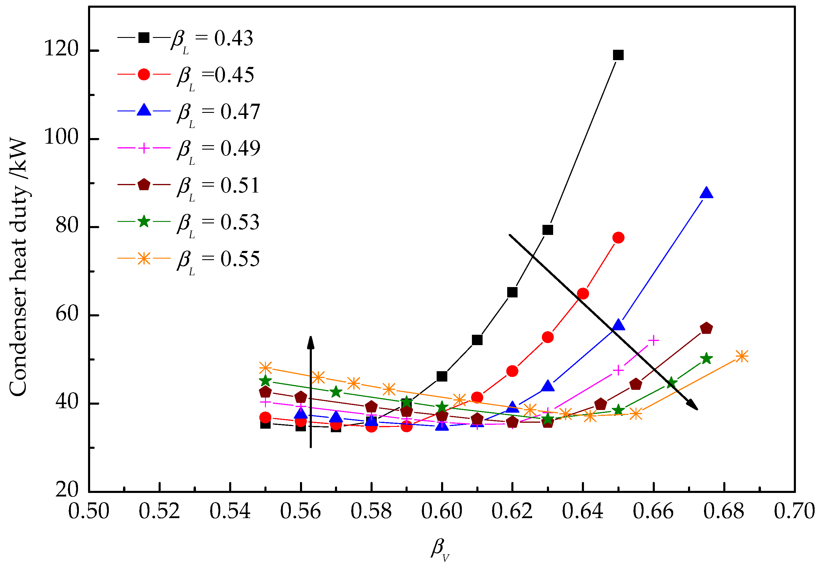
Figure 8, for a given vapor split ratio
βV, the heat duty of condenser decreases first and then increases with the increase of liquid split ratio
βL, as shown in
Figure 9. Consequently, there also exists an optimal
βL that minimize the heat duty of the condenser. When the liquid split ratio is less than the optimal value, the condenser and reboiler heat duties increase with the increase of vapor split ratio and vice versa. Therefore, there is always an optimal liquid split ratio where both the condenser and reboiler heat duties reach minimum when the vapor split ratio is specified.
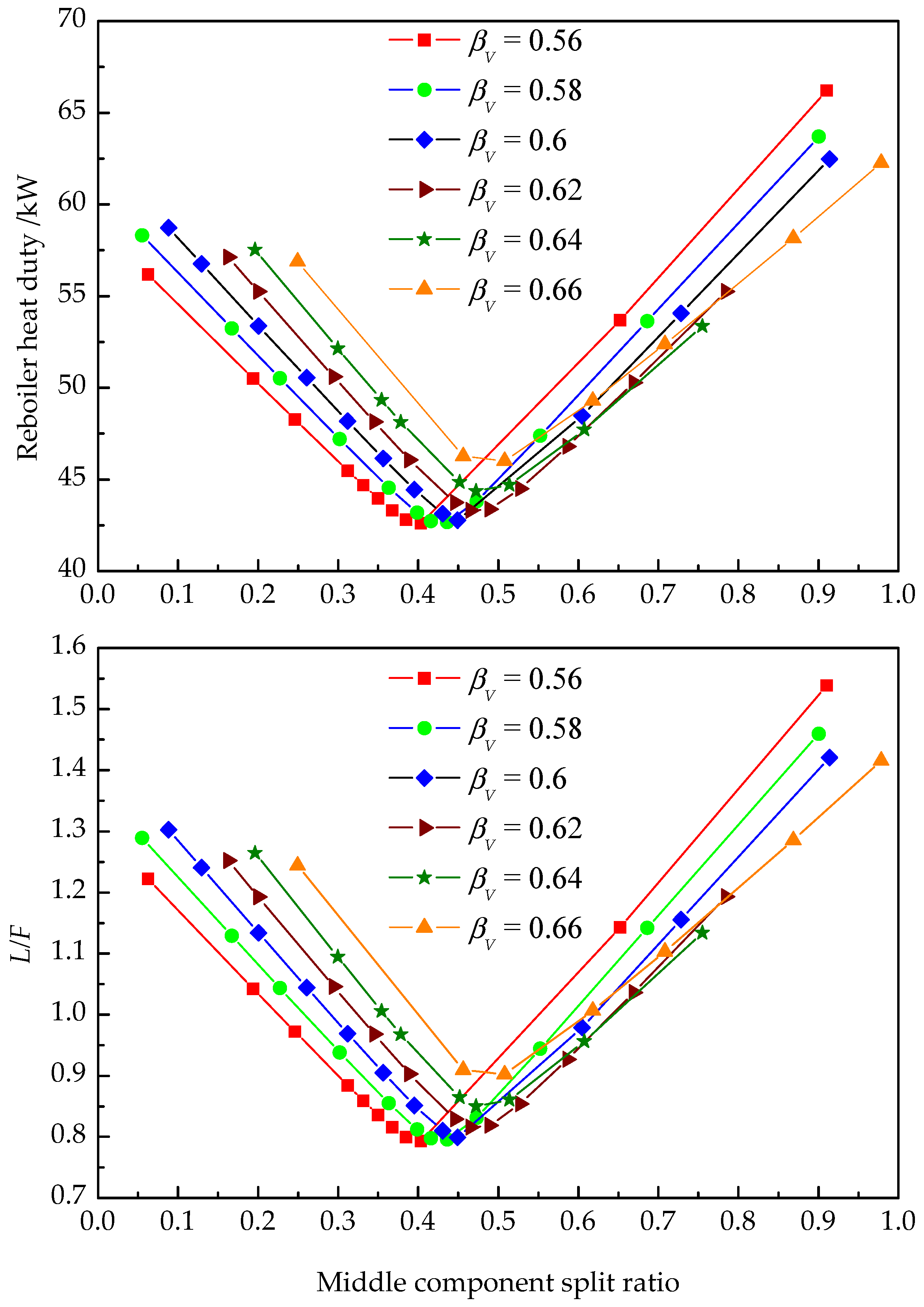
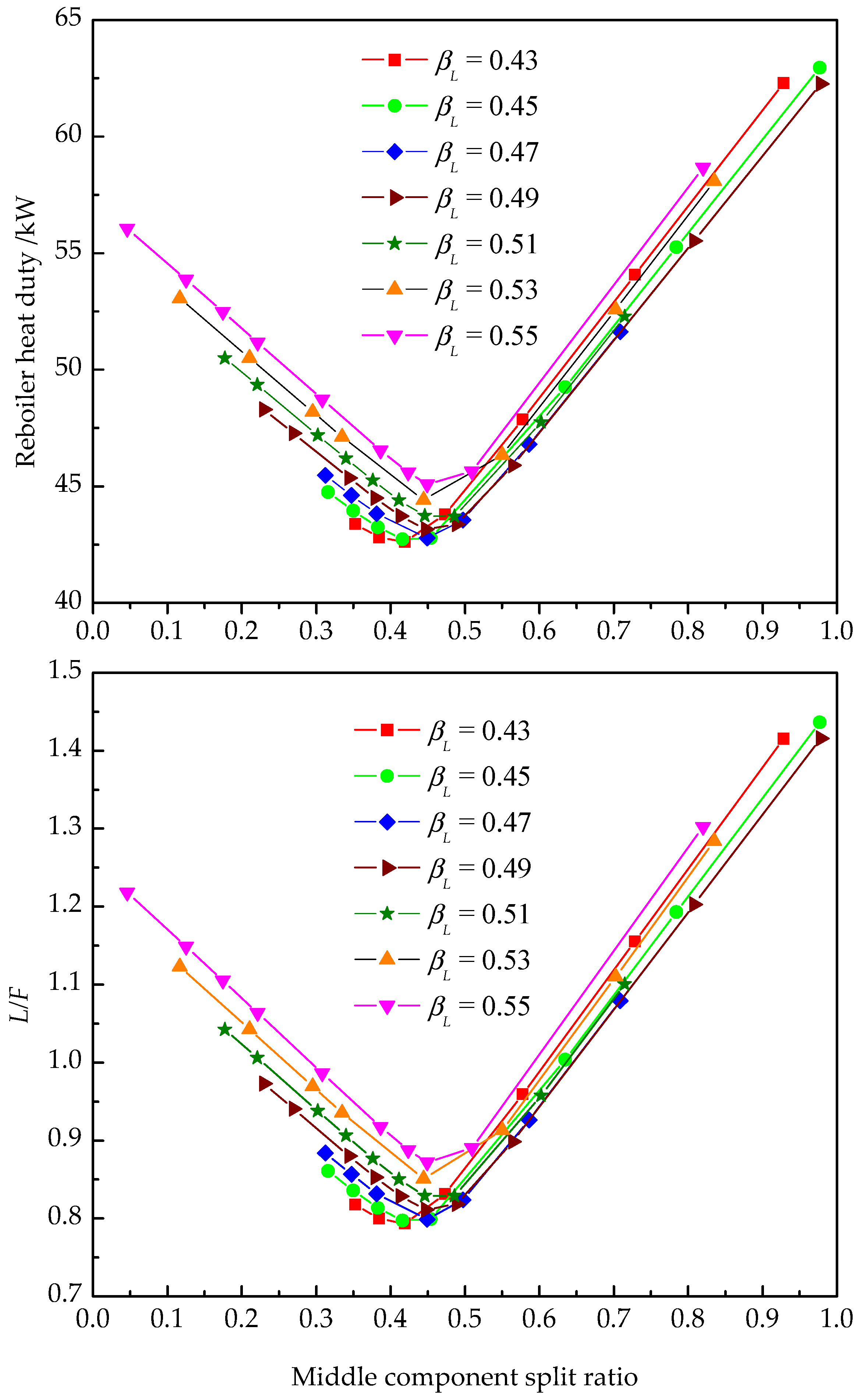
3.2. The Middle Component Split Ratio
In
Section 2, we define the middle component split ratio at the top and bottom of the pre-fractionator (Equations (15) and (16)). According to the definition, the middle component split ratio is determined by the liquid and vapor streams entering the pre-fractionator, which directly affects the overall heat duty of the DWC. In practice, the ratio of liquid reflux to feed (
L/
F) is commonly used.
Figure 10 and
Figure 11 show the behavior of the middle component split ratio at the top of pre-fractionator against the corresponding
L/
F under different liquid and vapor split ratios.
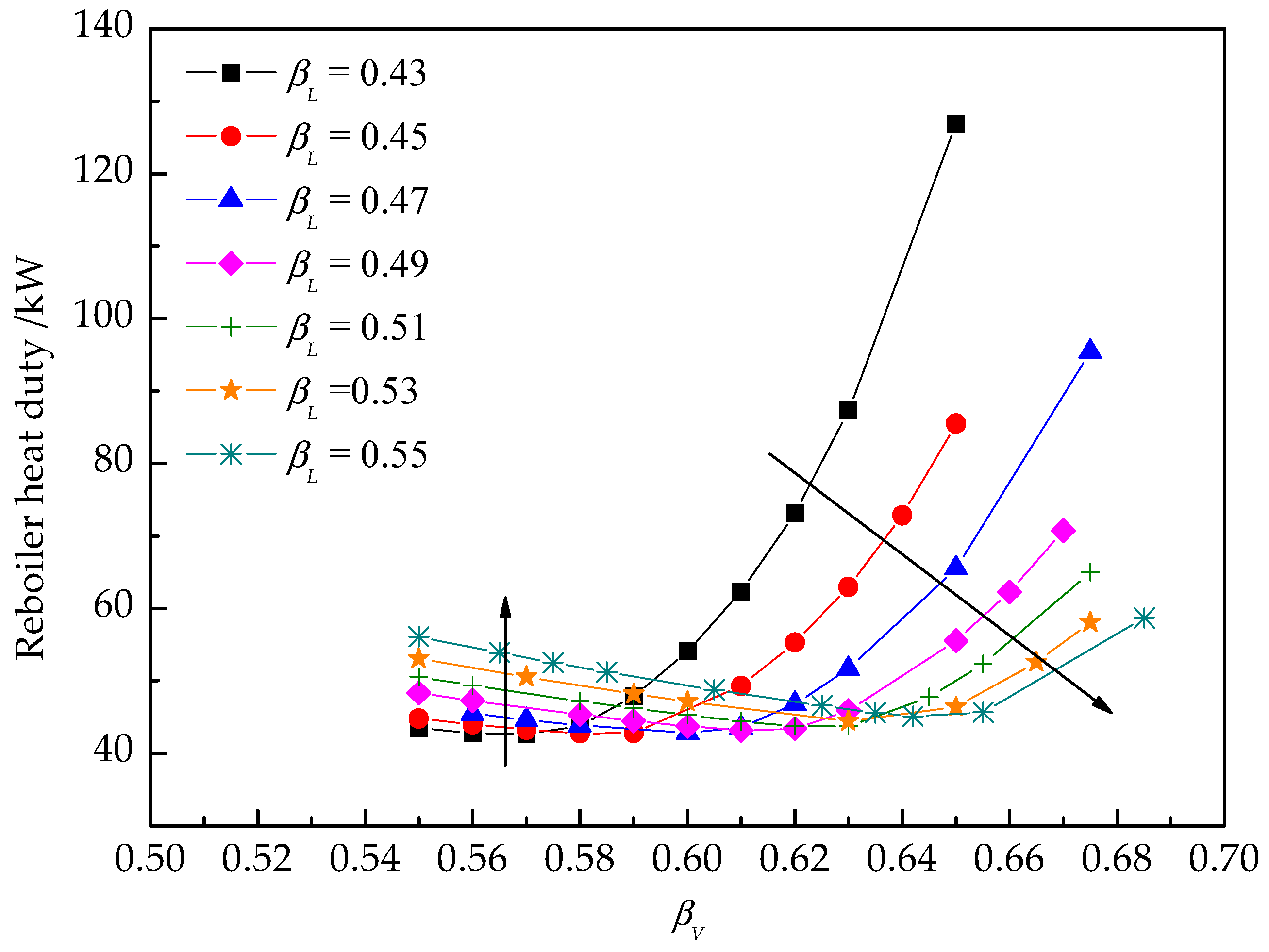
Figure 12 and
Figure 13 shows how both the reboiler and condenser heat duties vary with changes of the vapor split ratio. For a given liquid split ratio
βL, an optimal vapor split ratio can minimize the heat duty of both the reboiler and condenser. The results show that the separation performance is almost the same as that in the single distillation column, but the heat duty of the DWC increases dramatically.
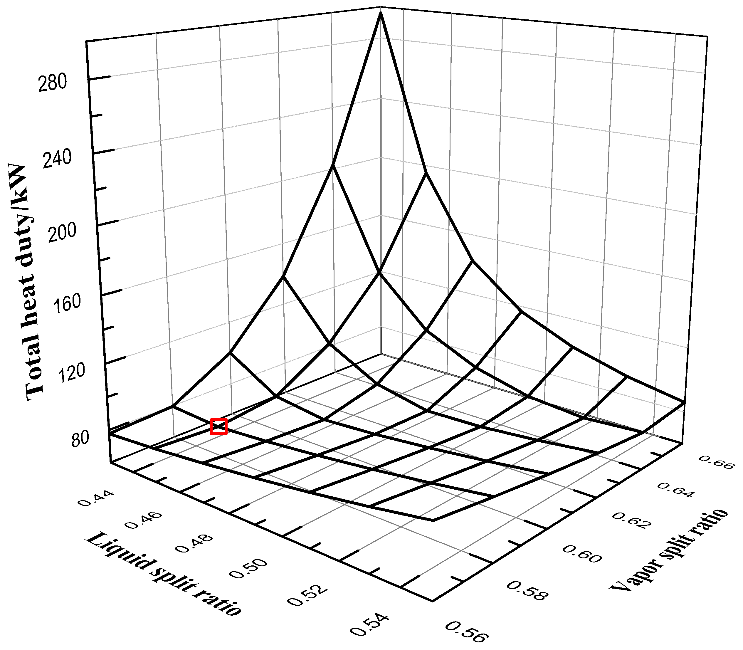
Figure 14 shows the total heat duty under different liquid and vapor split ratios. Total heat duty is the sum of condenser heat duty and reboiler heat duty. We can see that the minimum total heat duty is 77.557 kW when liquid split ratio is 0.45 and vapor split ratio is 0.58. Based on the above analysis, the liquid and vapor split ratios strongly affect the heat duty of the DWC. Hence, it is necessary to decide the liquid and vapor split ratio appropriately to design a good DWC.
For specified vapor and liquid split ratio, when the middle component split ratio increases, heat duty decreases first, and then reaches the minimum before increasing. The trend of L/F is consistent with that of the heat duty, i.e., there is a minimum L/F for a given separation requirement, which means the minimum energy consumption. In practice, we cannot control the middle component split ratio. Instead, the liquid reflux rate (L) and feed rate (F) are controlled. Consequently, liquid split ratio and the minimum L/F need to be decided to keep the energy consumption at the optimal value.
3.3. The Effect of Mixing
We define the degree of mixing above (Equations (17) and (18)).
Figure 15 and
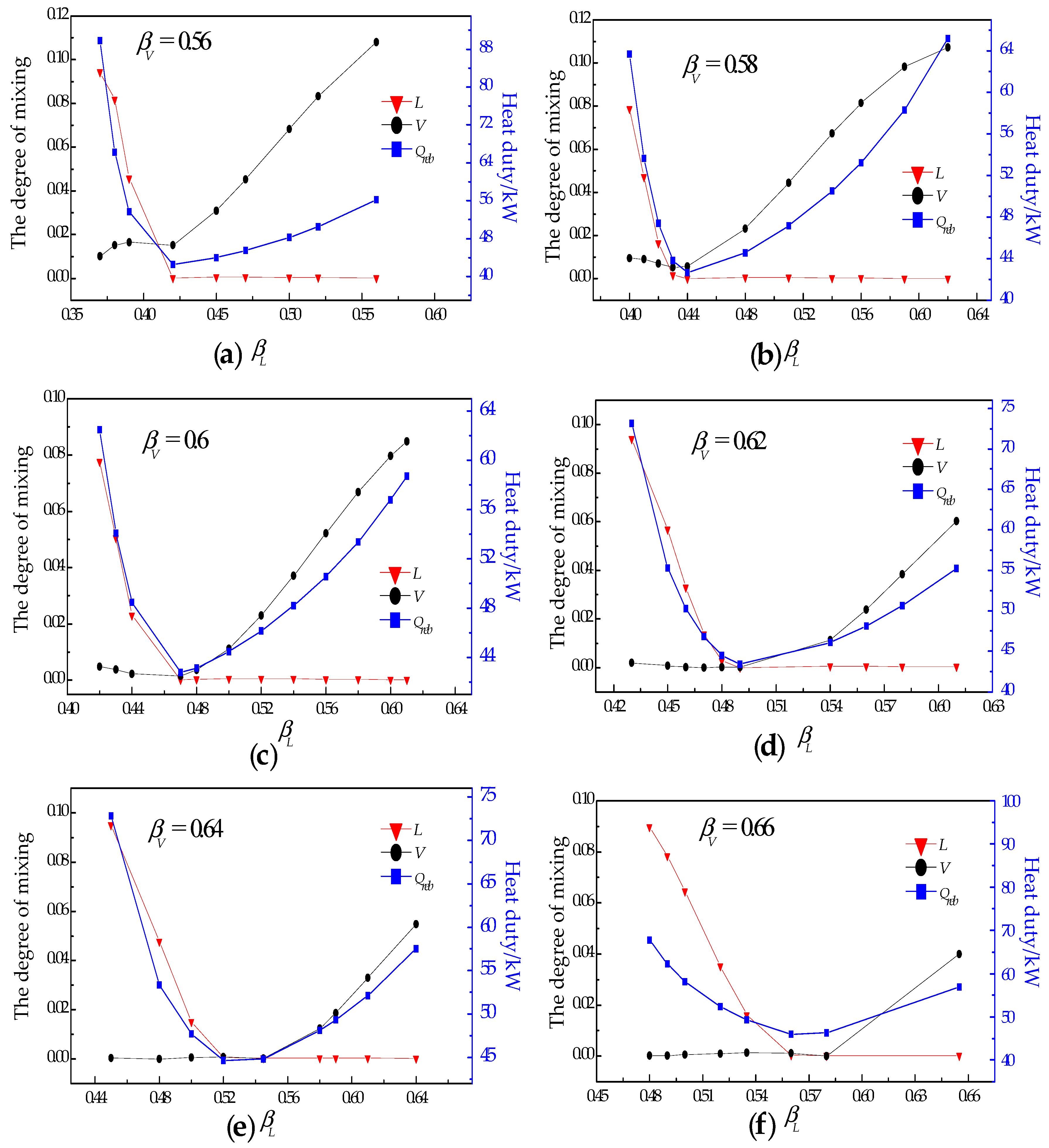
Figure 16 illustrate the effect of mixing under different liquid split ratios and vapor split ratios. We can see in
Figure 15 that, for a specified vapor split ratio, heat duty decreases first and then increases with the increase of liquid split ratio. Higher heat duties are obtained when the degree of liquid mixing or the degree of vapor mixing is high, while, at the same time, higher or lower liquid split ratio will lead to increased degree of mixing. Since the separation conducted within a distillation column generally follows the monotonic component change along the stages in both directions, the interruption of the monotonic property causes the mixing effect, which is hinders separation. However, when the liquid or vapor from both sub-columns meet at the end of dividing wall, the monotonic property being interrupted is inevitable. Hence, the degree of mixing can be assessed to evaluate the energy efficiency of the DWC.
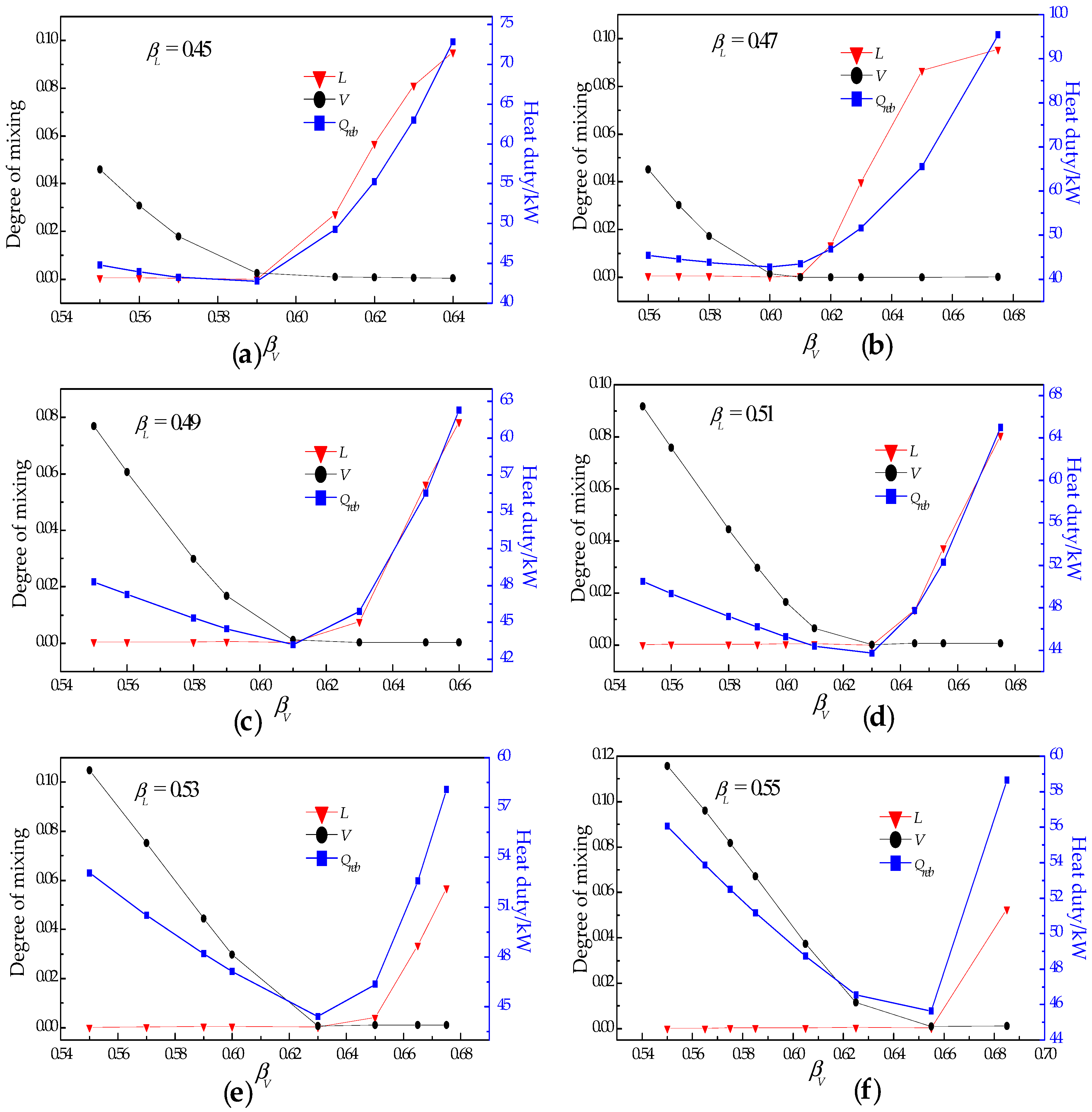
Accordingly, the results in
Figure 16 are similar to those in
Figure 15. Based on the above results, it can be concluded that suitable liquid split ratio and vapor split ratio can reduce the degree of mixing, hence increase the separation efficiency.
To summarize, three indicators are discussed through the rigorous DWC model in this section. The first two are for design purposes, and the last reveals the intrinsic reasons that cause unnecessary energy loss in a DWC configuration. It is obvious that the three indicators are intercorrelated, and their analysis aids DWC design and evaluation.


